Article

Toward Cost-Effective Timber Shell Structures through the Integration of Computational Design, Digital Fabrication, and Mechanical Integral ‘Half-Lap’ Joints

1
Faculty of Architecture and Urban Planning, Ricardo Palma University, Santiago de Surco, Lima 15039, Peru
2
Digital Design and Fabrication Laboratory—LADDFAB, Santiago de Surco, Lima 15039, Peru
3
Training Research and Innovation Laboratory—LABIFIARQ, Santiago de Surco, Lima 15039, Peru
4
Peruvian University of Applied Sciences, Santiago de Surco, Lima 15039, Peru
5
Federico Villarreal National University UNFV, San Miguel, Lima 15088, Peru
*
Author to whom correspondence should be addressed.
Buildings 2024, 14(6), 1735; https://doi.org/10.3390/buildings14061735
Submission received: 18 April 2024 / Revised: 22 May 2024 / Accepted: 24 May 2024 / Published: 9 June 2024

Abstract

:
In a global context, where the construction industry is a major source of CO2 emissions and resource use, is dependent on concrete and its risks, and lags behind in digitalization, a clear need arises to direct architecture towards more practical, efficient, and sustainable practices. This research introduces an alternative technique for building timber space structures, aiming to expand its applications in areas with limited access to advanced technologies such as CNCs with more than five axes and industrial robotic arms. This involves reconfiguring economic and ecological constraints to maximize the structural and architectural advantages of these systems. The method develops a parametric tool that integrates computational design and manufacturing based on two-axis laser cutting for shells with segmented hexagonal plywood plates. It uses a modified ‘half-lap joint’ mechanical joint, also made of plywood and without additional fasteners, ensuring a precise and robust connection. The results demonstrate the compatibility of the geometry with two-axis CNC machines, which simplifies manufacturing and reduces the cuts required, thus increasing economic efficiency. The prototype, with a span of 1.5 m and composed of 63 plywood panels and 163 connectors, each 6 mm thick, supported a point load of 0.8 kN with a maximum displacement of 5 mm, weighing 15.1 kg. Assembly and disassembly, carried out by two students, took 5 h and 1.45 h, respectively, highlighting the practicality and accessibility of the method. In conclusion, the technique for building timber shells based on two-axis CNC is feasible and effective, proven by practical experimentation and finite element analysis.

1. Introduction

Currently, the construction industry is a major source of CO2 emissions and is highly dependent on concrete and its associated risks [1], along with a lack of digitalization [2]. This necessitates directing architecture towards more efficient and sustainable practices. In this context, timber shell structures offer a significant opportunity to achieve new levels of efficiency in time and energy consumption in the processes of manufacturing, assembly, and dismantling.
Shell structures, an ancient construction technique, used in structures such as Roman domes and Gothic vaults, owe their resistance to their shape, which allows a natural and predictable distribution of their loads [3]. They are highly valued in architecture and engineering for their flexibility in design, as seen in modern applications like geodesic domes and hyperbolic paraboloids. However, traditional shell construction methods, which include techniques such as pouring concrete or applying fiber sheets, have proven to be inefficient in terms of resources and costs due to the need for extensive and labor-intensive formwork [4]. Consequently, there was a decline in popularity after an experimental phase between the 1950s and 1970s, and they were largely replaced by more conventional building methods.
Research exploring the combination of spatial structural systems and engineering wood products (EWPs) offers a unique opportunity to overcome the economic and ecological limitations of shell structures. Furthermore, it leverages technological advances such as computational design and digital manufacturing to create customized and complex structures efficiently and sustainably as seen in Figure 1. This is highlighted by Weinand [5], a prominent researcher in the field.
In the construction of timber shell structures, innovative designs stand out, such as the “livMatS Biomimetic Shell” at the University of Freiburg, which employs segmented timber cassettes optimized through robotic fabrication and assembly techniques [6]. This project uses 27 mm three-layer spruce panels (cross-laminated timber, CLT) for the lower plates, 80 mm laminated spruce edge beams (glue-laminated timber, GLULAM), and 21 mm and 32 mm spruce panels for the cover plates; all part of the engineered wood products (EWPs) family. The plates are joined by means of cross-screwed joints, ensuring structural stability [7]. Another significant example is the “BUGA Wood Pavilion”, which uses robotic prefabrication to create large-scale timber structures [8]. Additionally, the “Annen Head Office” in Manternach, Luxembourg, employs a shell system of beech laminated veneer lumber (LVL) plates assembled solely with wood–wood connections without additional fastening elements [9].
The types of wood used, such as plywood, CLT, and GLULAM, are selected for their strength and durability, making them suitable for structural applications. To enhance these properties, chemical and thermal treatments are essential. These treatments improve durability, fire resistance, and insect protection, ensuring the longevity and structural performance of timber shells.
Despite significant technological advances in the creation of timber spatial structures, challenges remain, particularly in regions like Peru. The lack of access to CNC machines with more than five axes raises questions about the viability and accessibility of these construction systems in diverse geographical and economic contexts [10]. To fully realize the advantages and overcome these limitations, it is crucial to consider simpler and more accessible production approaches that enable the successful implementation of these systems in less advantaged regions.
In this context, the research aims to overcome the knowledge gap and identified limitations by addressing the central question: How can shell structures be designed and manufactured efficiently using algorithmic processes within the technological limitations of two-axis CNC machines to promote more efficient and sustainable architectural practices? To address this question, the study discusses processes such as discretization of surfaces, form finding, planarization, and the design of integral mechanical joints without additional fastening. It also covers nesting and labeling, digital manufacturing, assembly and disassembly, structural analysis, and physical prototyping, all while considering the restrictions of two-axis CNC machines. Consequently, the general objective is to evaluate the feasibility of designing and manufacturing shell structures using segmented plywood plates through algorithmic processes, incorporating the limitations of two-axis CNC machines to expand sustainable construction practices, particularly in environments with limited technological capabilities.

1.1. Importance of Research

This research highlights wood as an innovative structural alternative to steel and concrete, revitalizing shell structures due to its effectiveness and lightness. Wood is not only renewable but also offers significant benefits in terms of energy efficiency and sustainability [11], positioning it as a constructive solution for the future.
This project aims to catalyze change in the perception and use of innovative construction materials in Peru. With its vast forestry potential and a central timber industry, Peru needs to increase the added value and diversify timber production [12]. Despite global interest in advanced construction technologies that favor wood, such as CLT, GLT and LVL, Peru faces limitations due to the nascent maturity of its sector. This situation highlights the importance of academic research in promoting the use of sustainable and advanced technologies adapted to the Peruvian context through integrated strategies and collaborations between universities, the construction industry, and the timber sector.

1.2. Shell Structures: To Resist through Form

Shell structures, characterized by their curved and thin shapes, efficiently redistribute external loads perpendicular to their surface and generate internal forces in their tangent plane. This load management capacity is observed both in historical constructions and in natural elements and cells, evidencing its effectiveness and the decisive influence of gravity on its design [13]. These structures are commonly manufactured with materials such as concrete, masonry [14], and wood [15], noted for their functionality and efficiency.

1.3. Engineered Wood Products (EWPs)

Engineered wood products (EWPs) are essential for the development of advanced wood construction. These products, which include standardized beams and panels, improve performance and sustainability [16,17]. Prominent examples of EWPs include glulam (GLT), valued for its rigidity and durability in arches and columns; CLT, noted for its lightness and prefabricated potential; and plywood, recognized for its high strength and consistent properties, suitable for various construction applications. Although they may be more expensive, EWPs offer significant design and sustainability advantages, competing effectively with traditional and mineral-based materials [17].

1.4. Timber Plate Shell Structures (TPS)

Timber plate shell (TPS) structures represent a significant advancement in timber construction, particularly since the creation of the first folded plate structure in 2001 [15]. These structures use engineered wood and advanced technologies, such as five-axis CNC and robotic arms, allowing for complex custom designs [4]. There are two main types of TPS: folded shell structures and segmented plate structures. This research focuses on segmented plate structures due to their three-dimensional configuration and precise joints, which enhance structural integrity and aesthetic appeal.

1.5. Segmented Timber Plate Shell Structures

Segmented plate shells, with their three-dimensional design and lightness, offer several advantages, including construction efficiency, environmental benefits, and attractive aesthetics. They facilitate prefabrication and reduce assembly times, providing complete solutions that include enclosures and finishes. However, their geometric complexity can present challenges in production and design. These structures can use different layers of materials such as LVL, OSB, CLT, MDF, or plywood. They adapt to specific needs by integrating several pieces to reinforce edges or create hollow components, demonstrating versatility in materials use according to project demands.

1.5.1. Plates

In segmented plate shells, wood plates, whether solid in one piece or composed of several parts, are essential for structural efficiency (Figure 2a). Composite boards improve material distribution, reinforcing key edges for better force transfer. Solid boards made of materials such as plywood, LVL, OSB, or CLT, are effective in transmitting forces [18]. Reinforced plates increase rigidity and allow for more efficient joints, while hollow components improve forces transfer and facilitate connections, as demonstrated in the BUGA Wooden Pavilion [19].

1.5.2. Joints

Joints in wood shell structures are crucial as they allow efficient transfer of forces and provide rigidity without affecting appearance, cost, or manufacturing speed. These joints must be adjustable to specific needs, easy to disassemble, and ecological. The design must handle different types of forces and limit deformations. It is important to ensure proper direction when mounting plates. Although mounting may vary, certain shapes or joints require a specific order. Ease of assembly can influence characteristics such as rigidity. Precision manufacturing of joints is vital to the stability, fire resistance, and efficiency of assembly, highlighting the need for a comprehensive approach to the design and construction of these structures [19].
The literature describes a wide range of joints in wooden structures, including geometric connections like tenon and dovetail joints, as well as the use of screws, adhesives, and elements without external fixations. These techniques are classified into joints with and without additional fasteners, and they stand out for their structural and aesthetic efficiency.
In integral mechanical joints with fixing elements, two predominant techniques stand out: tenon and dovetail joints (Figure 2b) and fully threaded screws. The former, key in carpentry due to their rigidity, rely on precise geometries and detailed assembly sequences, requiring high precision manufacturing, as demonstrated in projects like the BUGA Wooden Pavilion [19]. These joints require specialized equipment such as six-axis CNC milling machines, reflecting their complexity and precision [20]. On the other hand, fully threaded screws (Figure 2c), essential for structural rigidity, allow effective insertion into various types of wood and derivatives. The strategic placement and length of the screws are crucial for joint strength and stiffness [20]. This approach has been successfully tested in projects like the Landesgartenschau Exhibition Hall, illustrating how the proper combination of these techniques can overcome structural challenges, particularly axial and shear forces [21].
Figure 2. Types of plates and joints. The figure shows (a) Three types of plates: solid plates, an edge-reinforced plate, and a hollow component [19]. (b) Two types of joints: finger joint (left) and a dovetail (right) [19]. (c) Another type of joint: crossing screw connection [21].
Buildings 14 01735 g002
Integral mechanical joints without external fixings (Figure 3) represent an advance in the construction and design of segmented wooden structures, combining precision and sustainability through advanced cutting techniques. These joints, which facilitate self-assembly, stand out for their structural and aesthetic solidity without additional elements. They demonstrate economy and ease of assembly and disassembly, as seen in the details of folded plate structures with dovetail joints, developed by Robeller et al. (Figure 3), as noted by Weinand [5].
Wooden plugs, such as the X-Fix [22], illustrate this approach with their innovative design, typically employing five-axis CNC technology. This allows for precise installation and resistance to various tensions, demonstrating their effectiveness in both standard and experimental applications, supported by research from Robeller and Viezens [23]. Meanwhile, joints with dowels and biscuits stand out for their adaptability and aesthetics, evolving towards systems that allow for adjustments and material reuse, as seen in the HexBox project [24]. This evolution from traditional techniques to more adaptable approaches underscores the relevance of integral mechanical joints in contemporary architecture, marking a significant step towards innovation and sustainability in wood usage.

2. Materials and Methods
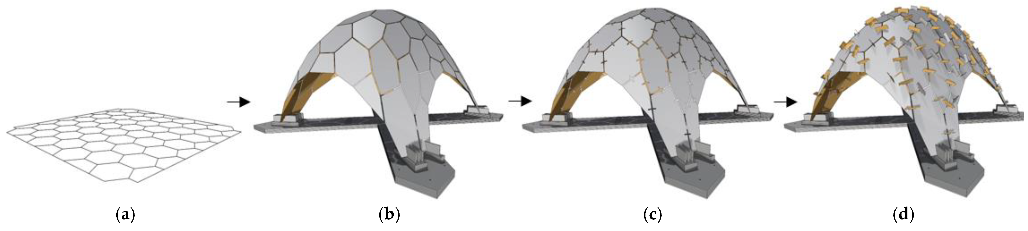
This study adopts a quantitative and experimental methodology to explore the creation of segmented shells of plywood. These shells are based on synclastic surfaces, which curve in the same direction at every point. The process covers digital conceptualization to structural analysis using 2-axis CNC technology. Simplicity and weight reduction are prioritized to minimize costs. Solid wood plates are chosen for their ease of prefabrication and robustness.

2.1. Base Geometry

This study focuses on the influence of the panel configuration pattern on the structural stability of segmented wooden shells. It highlights the importance of a trivalent geometry (Figure 4a), as pointed out by Li and Knippers [25]. This configuration minimizes the need for rigid connections, allowing structural stability even with weak connections. This characteristic is observed in natural structures according to Wester, as noted by Gabriel [26] and La Magna et al. [27]. The project adopts a structure based on hexagonal polygon meshes, which are essential to define the geometry and ensure the effectiveness and stability of the shell. This initial approach not only promotes sound structural design but also guides the development of efficient and sustainable manufacturing techniques.

2.2. Form Finding and Planarization

In this study, we use Kangaroo3d, a component of Grasshopper3d [28,29], which is part of Rhinoceros 3D version 7, to simultaneously address the challenges of form finding and planarization (Figure 4b). Form finding focuses on allowing the structure to find its optimal configuration based on equilibrium under applied loads. This approach diverges from mathematically defined shapes or those generated without regard to structural performance. This process guarantees inherent structural efficiency in the resulting forms. The methodology to shape the structure is mainly based on the application of dynamic relaxation and co-planarity techniques. These techniques help achieve a three-valence geometry suitable for synclastic surfaces without significantly altering the original configuration. By experimenting with Kangaroo3d, we identified strategies for the planarization of hexagonal patterns. These strategies included adjusting the anchoring strength of the initial positions of the vertices, progressively increasing the slider intensity of the planarization component, and finally applying Laplacian smoothing.

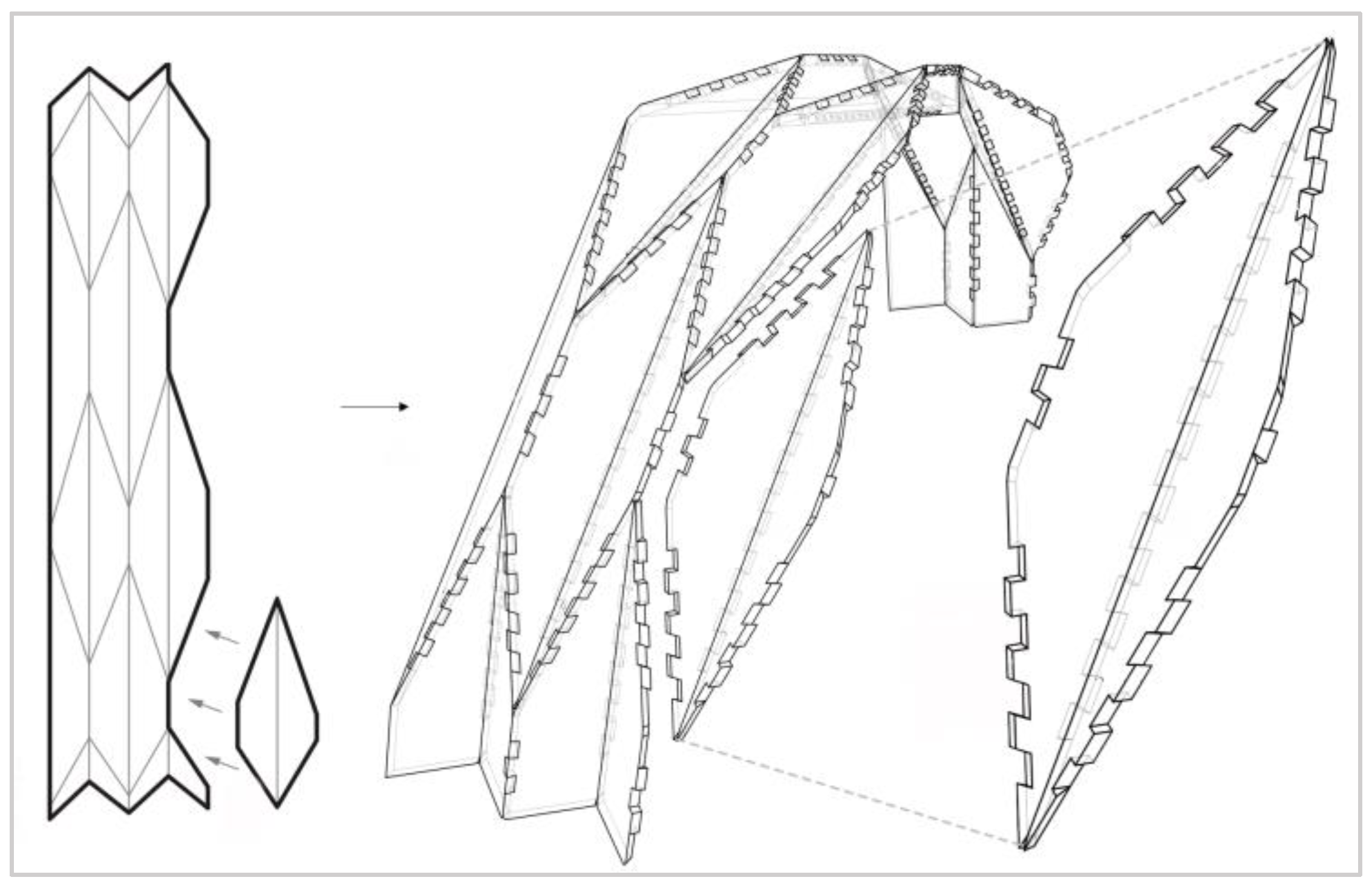
2.3. Unions and Laser Cutting

In this section, we explore half-lap joints adapted to the limitations of 2-axis CNC cutting. These joints are versatile for double-curvature structures [30], reciprocal structures, and flat assemblies such as walls and slabs. Practical examples of their use include the New View pavilion by Nabaei and Weinand [31], which employs plywood joined by “U” cuts, and studies on reconfigurable folding structures by Agostino and Pone [32]. The use of laser cutting in the creation of these joints allows for precise and repeatable fabrication, ensuring high accuracy in the assembly of components. This method reduces material waste and increases the efficiency of the manufacturing process, making it a viable option for both small-scale and large-scale projects.
We address the limitations to rotational loading of half-lap joints pointed out by Aranha et al. [33], with a specific variant for flat hexagonal structures. This variant improves load transfer without compromising manufacturing. The innovation lies in a specific connection for hexagonal structures that maintains the separation between plates (Figure 4c), reduces manufacturing complexity, and facilitates load transfer. The main element of the joint functions as the backbone of the connection system (Figure 4d). These elements are placed along the parallel edges of the hexagonal plates, except for those on the outer or perimeter edges of the structure (Figure 4d and Figure 5). This component, cut at two of its ends, is positioned perpendicular to the adjacent plates. The latter are adjusted slightly to fit precisely with the main element through their edges. Determining appropriate manufacturing tolerances is essential to ensure both efficient assembly and structural stability.
The connection is reinforced with two complementary pieces, which function as locks, placed perpendicularly to the main element and on each plate. These pieces align approximately with the direction of the common edge between the plates, increasing the security of the assembly. For installation, two small cuts are required in both the main element and the plates, facilitating placement. These locks play a vital role in preventing lateral movement of the plates and their rotation, which is essential for the overall integrity and stability of the structure. The connection system optimizes both the assembly and the mechanical performance of the structure. It guarantees a firm union between the flat wooden plates in a hexagonal pattern, preserving the aesthetics and functionality of the design (Figure 5 and Figure 6).
The joints are made with precision using laser cutters, which Groenewolt [19] highlights for their importance in assembly and structural stability, as shown in Figure 5. Despite challenges such as high energy consumption and edge discoloration, Robeller and Weinand [34] demonstrate the advantages of laser cutting. They highlight its efficiency and ability to make precise cuts, essential for the integrity of the structure. This approach highlights the need to carefully select the most appropriate cutting method, balancing efficiency, quality, and safety.

2.4. Labeling and Nesting

To facilitate the assembly process of 63 boards and 163 unique components, including connectors and locking elements, we developed a detailed labeling system. Each main board and connector were marked with a unique number, supplemented on the connectors by the numbers of adjacent panels. The edges of the panels were also inscribed with the numbers of their main connectors, facilitating assembly without additional documentation. Locking parts were labeled with the codes of their main connectors and corresponding panels, ensuring efficient and accurate assembly on site (Figure 5). For the cutting process, we converted the 3D designs into 2D plans, reorganizing the design information to optimize material use using OpenNest (version 1.5.1), a tool for nesting shapes efficiently [35,36]. This adjustment allowed for efficient arrangement of parts based on their shape, size, and the laser cutter’s working area limitations, which are 1300 × 900 mm. This minimized material waste and reduced costs thanks to planning that took 9 min (Figure 7a,b).

2.5. Assembly and Disassembly

The assembly of the structure was carefully planned through the numerical sequencing of the components, starting with base elements from the ground and moving toward the top. Precision CNC cutting was crucial for a smooth assembly, especially during the initial phase of joining main boards and connectors. This process was carried out collaboratively by two students, taking 8 h for assembly and 1.45 h for disassembly. The installation of the locking elements, designed to reinforce stability, marked the final stage, ensuring the structural integrity and proper alignment of each piece in the whole. Repeated assembly and disassembly tests demonstrated a notable improvement in efficiency, reducing assembly time from 8 to 5 h, without damage to the parts, evidencing the durability of the materials and the effectiveness of the design.

2.5.1. Material Characterization

The material characterization of the prototype includes 6 mm plywood elements for the hexagonal plates, main connectors, and latches. The mechanical properties used for the analysis were based on the Finnish Plywood Manual [37]. For this, 6.5 mm birch plywood was used. We adjusted its values to 75% to align the properties with the 6 mm material, compensating for the difference in thickness. The plywood used did not undergo any additional chemical or thermal treatments. This ensured that the mechanical properties matched those specified in the Finnish Plywood Manual, providing a consistent basis for evaluating structural performance.

2.5.2. Modeling for Simulation

The structural simulation was carried out with Karamba3D (version 2.2.0.180 for Rhinoceros 3D version 7) [38], a finite element analysis software that allows detailed integration of geometry, material properties, cross-sections, and definition of supports. This process enables precision in specifying loads and boundary conditions for a complete structural analysis.
The method transformed plates, connectors, and locks into triangular meshes to facilitate analysis. The supports, designed to emulate absolute embedment conditions, were set as completely fixed, eliminating any possibility of translation or rotation. With the assembled model, we proceeded to the analysis with the Karamba3D solver, which calculates the structural response to loads, including deformations and stresses. After analysis, the data were extracted and reintegrated into the collaborative design interface for review and final adjustment.

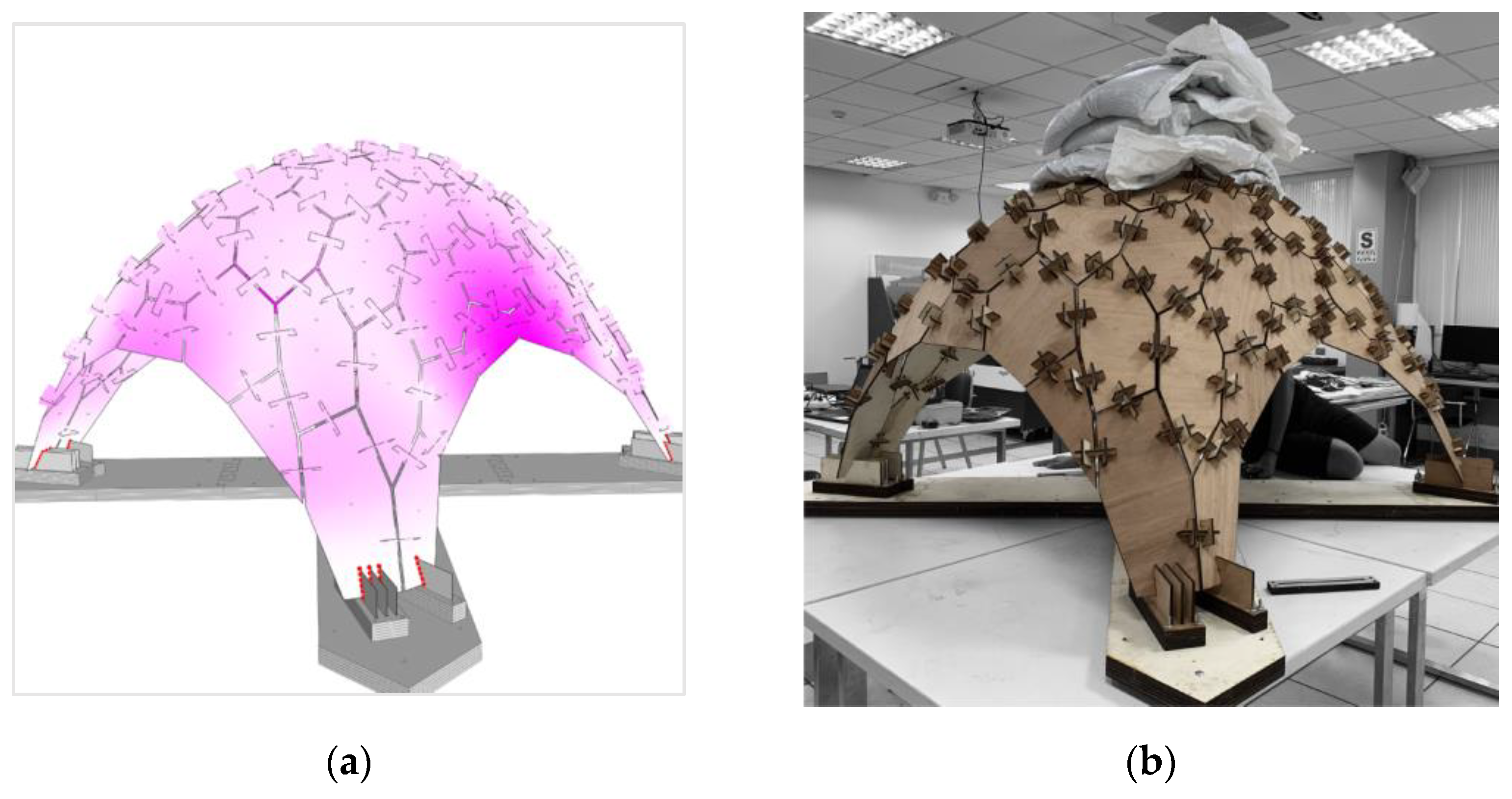
2.5.3. Loading Conditions

To evaluate the mechanical behavior of the structure, it was first analyzed under its own weight in Karamba3D, increasing the load by a factor of 1.5 to simulate extreme conditions and verify its structural resistance (Figure 8a). Then, these results were validated with a physical prototype, applying a load of 0.8 kN, as seen in Figure 9b. This hybrid method of digital analysis and physical testing provides a comprehensive view of structural performance under varied loading conditions.
Considering that the main measurement in both the simulation and the prototype was the displacement, it is important to mention the Peruvian standard “Norma Técnica de Edificación E.010”, which establishes requirements for density, modulus of elasticity, and allowable stresses. According to this standard, the maximum allowable deflection for wood structures is L/300 when considering the combination of permanent loads and live loads [39]. This value ensures that deformations remain within acceptable limits, guaranteeing the stability and safety of the wood shell structures.

2.5.4. Foundation

The design of the foundation was based on the homogeneity of materials with the rest of the structure, opting for four 6 mm thick plates located perpendicular to the ground at the support points. These plates are attached to the main shell through half-lap joints and inserted into wooden blocks, which are fixed with boards diagonally, as shown in Figure 9b.

2.5.5. Linear Static Analysis

Figure 9 shows the structure with a span of 1.5 m and a thickness of 6 mm, which is restricted in displacement at four points in all directions. Two scenarios were evaluated: in the first scenario, a simulation in Karamba3D revealed that a load equivalent to 1.5 times the weight of the structure (in kN) produced a maximum displacement in any direction of up to 0.2 mm. On the other hand, the physical prototype was subjected to a load of 0.8 kN, which resulted in a vertical displacement of 5 mm measured with a laser instrument (Figure 9b).
On the other hand, experiments were carried out after the construction of the prototype where we established a highly demanding range on the scale of the diagram to visualize the behavior of the compression forces in the structure (Figure 10b). The yellow areas indicate regions that have already exceeded the range established for the experiment, highlighting areas that potentially require different treatment. The red areas show the points with the highest levels of compression, while the white areas indicate the lowest levels of compression. Similarly, diagrams were generated to visualize the tensile stresses in the structure (Figure 10a). The areas in green are those that exceed the established ranges. The points with the highest levels of tension are marked in blue, while the areas with the lowest levels of tension are marked in white. This analysis can be the starting point for optimizing the use of connectors, for example, using different sizes.
A final experiment indicates that aligning the direction of the fibers of the plywood plates tangent to the main structural stress would improve the strength and efficiency of the design, especially against tension and compression. Visual analysis (Figure 10a) shows the optimal orientation of the plates, facilitating the identification and reinforcement of weak points by designers and engineers.

2.5.6. Optimization

As a structural optimization strategy, variability in connector placement was examined. Although in the physical prototype the connectors were placed in the center of the hexagonal edges, digital simulations suggested that “randomly” distributing the connectors along these edges, rather than keeping them in a centralized position, leads to better structural performance (Figure 11). This improvement is manifested in a significant decrease in displacement.
In the structural optimization addressed, the focus was exclusively on adjusting the position of the central connectors along the hexagonal edges using the optimization mechanism provided by Opossum [40]. Originally, the connectors were placed in the center of these edges, generating a displacement of 0.2047 mm. Using Opossum’s advanced simulation and optimization capabilities, the hypothesis was tested that a varied, non-uniform distribution of these connectors could improve structural performance. This meticulous process, which was carried out through 100 iterations over 30 min, demonstrated effective optimization by reducing the displacement to 0.1902 mm, demonstrating the effectiveness of Opossum in finding optimal solutions by modifying a single design aspect: the location of the central connectors.
It is crucial to note that this study is not intended to offer a definitive solution but rather to point out directions for future more detailed research. By limiting the analysis to the variability of the core connectors, we seek to illuminate the potential for seemingly minor adjustments to significantly improve structural efficiency. This preliminary approach opens the door to deeper investigations that could more broadly explore how modifications to connector layouts can influence the stability and performance of complex structures, using Opossum as a key tool in this exploration and optimization process.

3. Results

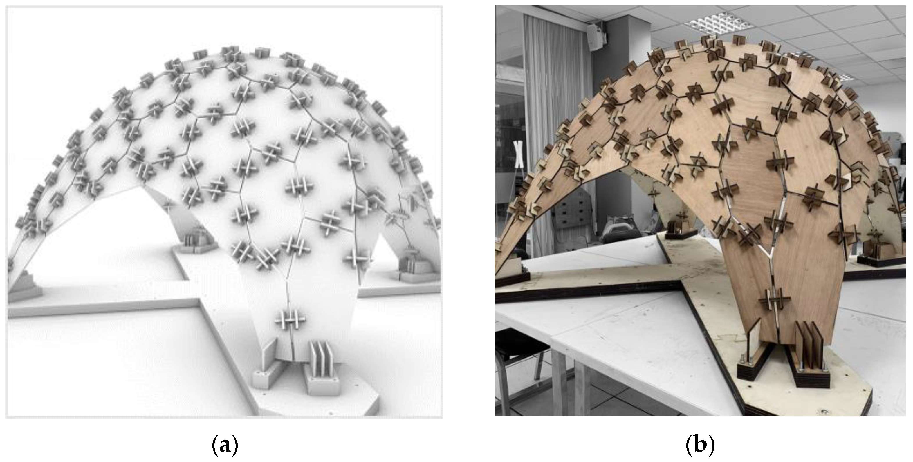
3.1. Prototype Performance

The prototype, composed of 63 panels and 163 connectors, withstood a point load of 0.8 kN with a maximum vertical displacement of 5 mm. According to the Peruvian building standard E.010 for wood structures, the maximum allowable displacement for beams subjected to permanent loads plus live loads is L/300. In our case, considering a span of 1500 mm, the maximum allowable displacement is 5 mm, so the prototype meets this regulatory criterion. Additionally, the applied load included an extra point weight, making the test more demanding and validating the robustness of the design. These results suggest that the design is structurally viable and compatible with two-axis CNC machinery, ensuring precision and consistency in manufacturing, which potentially facilitates large-scale replication.

3.2. Assembly and Disassembly Efficiency

The assembly process, carried out by two students, took 5 h, and disassembly took 1.45 h. Repeated tests showed a significant improvement in efficiency, reducing the assembly time from 8 to 5 h without damage to the parts. The precise, repeatable, and scalable cuts achieved through industrial laser cutting played a crucial role in this efficiency, highlighting the method’s practicality and strong potential for large-scale applications.

3.3. Structural Analysis

The structural simulation with Karamba3D revealed a maximum displacement of 0.2 mm under a load equivalent to 1.5 times the weight of the structure. In contrast, tests on the physical prototype showed a vertical displacement of 5 mm under a load of 0.8 kN. This discrepancy suggests that the simulations may underestimate the displacement under real load, indicating the need to adjust the model parameters or consider additional factors not included in the initial simulation. Despite this, both results confirm the overall reliability of the simulation methods and the robustness of the structural design. The optimized connectors significantly enhanced compression transfer and structural stability.

3.4. Connector Optimization

Optimization strategies using Opossum reduced the displacement from 0.2047 mm to 0.1902 mm by varying the placement of the connectors. This demonstrated the potential effectiveness of distributing the connectors along the edges of the polygonal plates instead of keeping them centralized, improving structural performance. The precise placement of connectors, facilitated by laser cutting technology, ensured the structural integrity and scalability of the design. These findings indicate strong potential for large-scale applications, maintaining structural resistance patterns, and facilitating efficient assembly and disassembly processes.

4. Discussion

4.1. Structural Integrity

The technique for constructing segmented wooden shells using two-axis CNC machines is practical and effective even under technological constraints. The successful load tests with a maximum displacement of 5 mm under a 0.8 kN load meet the requirements set by the building technical standard E.010, which allows a maximum displacement of L/300 for wooden structures. For our prototype, this translates to a maximum allowable displacement of 5 mm, confirming that the design preliminarily meets mechanical and aesthetic requirements and aligns with current construction standards. This compliance is particularly significant given that the test included an additional point weight, making the evaluation of the structure more demanding. The results of this study suggest that digital fabrication and computational design can be effectively integrated to create complex and robust structures. The use of industrial laser cutting for component fabrication ensures precise, repeatable, and scalable cuts, which further enhances the structural integrity and potential for large-scale applications. However, since these results are based on a small prototype, there is still a long way to go to conclusively affirm the success of this technique on a larger scale.

4.2. Assembly and Disassembly Efficiency

The efficient assembly and disassembly processes highlight the practicality and accessibility of the method, making it feasible for various applications. The reduction in assembly time from 8 to 5 h demonstrates the potential for efficient construction processes, which is crucial for practical applications in different contexts. The proposal not only meets design requirements but also offers a solution that improves assembly and disassembly processes. The precise, repeatable, and scalable cuts achieved through industrial laser cutting played a crucial role in this efficiency, underscoring the method’s potential for large-scale applications. This opens opportunities for future research in product recovery, highlighting disassembly as a profitable strategy due to technical advances and regulatory changes, and the increasing cost associated with waste management and the use of primary materials. The development of efficient disassembly lines becomes essential to automate and optimize product recovery according to Lambert and Gupta [41].

4.3. Connector Optimization and Future Research

The optimization of connector placement showed improvements in structural performance, underscoring the importance of proper connector distribution to enhance compression transfer. Future research should explore incorporating multiple connectors along the edges of the polygonal plates to improve compression transfer and overall structural performance. Additionally, it is suggested to explore non-structural applications of the system, such as formwork or interior design, leveraging its production capability with two- and three-axis machines. These areas of research have the potential to expand sustainable and efficient construction practices.

4.4. Implications and Applications

The findings of this study not only validate the proposed technique for constructing segmented wooden shells but also open new opportunities for the development and application of these structures in various contexts. This significantly contributes to sustainability and efficiency in architectural construction. The implications of this work are broad, providing a solid foundation for integrating advanced technologies in wooden structure manufacturing, thereby promoting more sustainable and economical practices in the construction industry. However, it is important to recognize that these results are preliminary and based on a small prototype, so further research and development are needed to confirm these findings on a larger scale. The integration of industrial laser cutting for precise, repeatable, and scalable component fabrication plays a crucial role in the potential for large-scale replication, ensuring the structural integrity and consistency necessary for broader applications.

5. Conclusions

The study demonstrates the feasibility of using segmented timber shells with integral mechanical joints fabricated using two-axis CNC machines. The prototype, despite its small scale, showed promising structural performance and efficiency in assembly and disassembly. One of the key findings is the significant role of optimized connectors, which enhanced compression transfer and overall structural stability. The relationship between the timber structure, composed of plywood panels, and its mechanical resistance was validated by the prototype’s ability to support a point load of 0.8 kN with a maximum displacement of 5 mm, meeting the E.010 standard for timber structures.
Although this study was based on a small-scale prototype, the results indicate a strong potential for large-scale reproduction of the structural design. An additional aspect that promises to facilitate scaling up is the use of industrial laser cutting for the fabrication of components. This technology ensures precise, repeatable, and scalable cuts, which are crucial for maintaining the accuracy and consistency required for larger applications. Further research and development are necessary to validate these findings on a larger scale, considering structural resistance patterns and potential design adaptations to maintain structural integrity. This approach holds significant promise for advancing sustainable construction practices, particularly in regions with limited access to advanced fabrication technologies.

Author Contributions

Conceptualization, E.P. and D.E.; methodology, L.C.; software, W.M.; validation, J.S., E.P., and D.E.; formal analysis, L.C.; investigation, W.M.; resources, J.S.; data curation, E.P.; writing—original draft preparation, D.E.; writing—review and editing, L.C.; visualization, W.M.; supervision, J.S.; project administration, E.P.; funding acquisition, C.V. All authors have read and agreed to the published version of the manuscript.

Funding

This research received no external funding.

Data Availability Statement

The original contributions presented in the study are included in the article, further inquiries can be directed to the corresponding author.

Acknowledgments

We would like to express our special thanks and gratitude to Engineer Alberto Ordoñez Curotto for his valuable comments and to Engineer José Luis Gutiérrez for his support in this study. Their expertise has been fundamental to the development of this research. Additionally, we extend our thanks to Mariano Porras Chang for his collaboration in reviewing the document.

Conflicts of Interest

The authors declare no conflicts of interest.

References

  1. Munir, Q.; Abdulkareem, M.; Horttanainen, M.; Kärki, T. A comparative cradle-to-gate life cycle assessment of geopolymer concrete produced from industrial side streams in comparison with traditional concrete. Sci. Total. Environ. 2023, 865, 161230. [Google Scholar] [CrossRef] [PubMed]
  2. Barbosa, F.; Woetzel, J.; Mischke, J. Reinventing Construction: A Route of Higher Productivity; McKinsey Global Institute: New York, NY, USA, 2017. [Google Scholar]
  3. Gohnert, M. Shell Structures: Theory and Application; Springer International Publishing: Cham, Switzerland, 2022. [Google Scholar]
  4. Menges, A.; Schwinn, T.; Krieg, O.D. Advancing Wood Architecture: A Computational Approach, 1st ed.; Routledge: London, UK, 2017. [Google Scholar]
  5. Weinand, Y. Design of Integrally-Attached Timber Plate Structures, 1st ed.; Routledge: London, UK, 2021. [Google Scholar]
  6. Skoury, L.; Treml, S.; Opgenorth, N.; Amtsberg, F.; Wagner, H.J.; Menges, A.; Wortmann, T. Towards data-informed co-design in digital fabrication. Autom. Constr. 2024, 158, 105229. [Google Scholar] [CrossRef]
  7. University ofof Stuttgart. livMatS Biomimetic Shell. Available online: https://www.icd.uni-stuttgart.de/projects/livmats-biomimetic-shell/ (accessed on 17 May 2024).
  8. Wagner, H.J.; Alvarez, M.; Groenewolt, A.; Menges, A. Towards digital automation flexibility in large-scale timber construction: Integrative robotic prefabrication and co-design of the BUGA Wood Pavilion. Constr. Robot. 2020, 4, 187–204. [Google Scholar] [CrossRef]
  9. Rad, A.R.; Burton, H.; Rogeau, N.; Vestartas, P.; Weinand, Y. A framework to automate the design of digitally-fabricated timber plate structures. Comput. Struct. 2021, 244, 106456. [Google Scholar] [CrossRef]
  10. Wagner, H.J.; Alvarez, M.; Kyjanek, O.; Bhiri, Z.; Buck, M.; Menges, A. Flexible and transportable robotic timber construction platform—TIM. Autom. Constr. 2020, 120, 103400. [Google Scholar] [CrossRef]
  11. Tupenaite, L.; Kanapeckiene, L.; Naimaviciene, J.; Kaklauskas, A.; Gecys, T. Timber construction as a solution to climate change: A systematic literature review. Buildings 2023, 13, 976. [Google Scholar] [CrossRef]
  12. García, J.M. Industria de la Madera; Ministerio de la Producción: Lima, Peru, 2017. [Google Scholar]
  13. Adiels, E. Differential Geometry and Structural Action of Vaults and Shells; Chalmers University of Technology: Gothenburg, Sweden, 2024. [Google Scholar]
  14. Ochsendorf, J. Guastavino Vaulting: The Art of Structural Tile; Princeton Architectural Press: New York, NY, USA, 2010. [Google Scholar]
  15. Weinand, Y. Complex Wood Structures; Birkhauser: Basel, Switzerland, 2016. [Google Scholar]
  16. Milner, H.R.; Woodard, A.C. Sustainability of engineered wood products. In Sustainability of Construction Materials; Khatib, J.M., Ed.; Elsevier: Amsterdam, The Netherlands, 2016; pp. 159–180. [Google Scholar]
  17. Woodard, A.C.; Milner, H.R. Sustainability of timber and wood in construction. In Sustainability of Construction Materials; Khatib, J.M., Ed.; Elsevier: Amsterdam, The Netherlands, 2016; pp. 129–157. [Google Scholar]
  18. Knippers, J.; Gabler, M.; La Magna, R.; Waimer, F.; Menges, A.; Reichert, S.; Schwinn, T. From nature to fabrication: Biomimetic design principles for the production of complex spatial structures. In Advances in Architectural Geometry 2012; Springer: Vienna, Austria, 2013; pp. 107–122. [Google Scholar]
  19. Groenewolt, A. Timber Plate Shells as a Roof Construction System Design and Fabrication of Trivalent Polyhedral Roof Structures for Applications in the Existing Building Stock; University of Stuttgart, Institute for Computational Design and Construction: Stuttgart, Germany, 2023. [Google Scholar]
  20. Krieg, O.D. Architectural Potential of Robotic Manufacturing in Timber Construction, Strategies for Interdisciplinary Innovation in Manufacturing and Design; University of Stuttgart, Institute for Computational Design and Construction: Stuttgart, Germany, 2023. [Google Scholar]
  21. Krieg, O.D.; Schwinn, T.; Menges, A.; Li, J.M.; Knippers, J.; Schmitt, A.; Schwieger, V. Biomimetic lightweight timber plate shells: Computational integration of robotic fabrication, architectural geometry and structural design. In Advances in Architectural Geometry 2014; Springer International Publishing: Cham, Switzerland, 2015; pp. 109–125. [Google Scholar]
  22. Schilcher. X-Fix. Available online: http://www.x-fix.at/ (accessed on 23 May 2024).
  23. Robeller, C.; Viezens, V. Timberdome: Konstruktionsystem für Brettsperrholz-Segmentschalen ohne Schrauben. In Proceedings of the 24. Internationales Holzbau-Forum IHF 2018, Garmisch-Partenkirchen, Germany, 5 December 2018. [Google Scholar]
  24. Robeller, C.; Barata, E.D.O.; Tagliaboschi, E.V.; Schmidt-Kleespies, F. Hexbox canopy: A segmented timber plate shell with hardwood wedge joints. J. Int. Assoc. Shell Spat. Struct. 2022, 63, 221–231. [Google Scholar] [CrossRef]
  25. Li, J.-M.; Knippers, J. Pattern and Form—Their Influence on Segmental Plate Shells. Proc. IASS Annu. Symp. 2015, 2015, 1–12. [Google Scholar]
  26. Gabriel, J.F. (Ed.) Beyond the Cube: The Architecture of Space Frames and Polyhedra; John Wiley & Sons: Nashville, TN, USA, 1997. [Google Scholar]
  27. La Magna, R.; Waimer, F.; Knippers, J. Nature-Inspired Generation Scheme for Shell Structures. In Proceedings of the International Symposium of the IASS-APCS Symposium, Seoul, Republic of Korea, 2012; Available online: https://elib.uni-stuttgart.de/handle/11682/122 (accessed on 23 May 2024).
  28. Piker, D. Kangaroo: Form Finding with computational physics. Arch. Des. 2013, 83, 136–137. [Google Scholar] [CrossRef]
  29. MDeuss; Deleuran, A.H.; Bouaziz, S.; Deng, B.; Piker, D.; Pauly, M. ShapeOp—A robust and extensible geometric modelling paradigm. In Modelling Behaviour; Springer International Publishing: Cham, Switzerland, 2015; pp. 505–515. [Google Scholar]
  30. Vestartas, P.; Weinand, Y. Joinery Solver for Whole Timber Structures. In Proceedings of the World Conference on Timber Engineering (WCTE 2020), Santiago, Chile, 23–26 August 2020. [Google Scholar]
  31. Nabaei, S.S.; Weinand, Y. Geometrical description and structural analysis of a modular timber structure. Int. J. Space Struct. 2011, 26, 321–330. [Google Scholar] [CrossRef]
  32. Agostino, R.; Pone, S. Adaptive cross-panel system: Digital fabrication for freeform architecture. Proc. IASS Annu. Symp. 2020, 2020, 1–12. [Google Scholar]
  33. Aranha, C.A.; Hudert, M.; Fink, G. Interlocking birch plywood structures. Int. J. Space Struct. 2021, 36, 155–163. [Google Scholar] [CrossRef]
  34. Robeller, C.; Weinand, Y. A 3D Cutting Method for Integral 1DOF Multiple-Tab-and-Slot Joints for Timber Plates, using 5-axis CNC Cutting Technology. In Proceedings of the World Conference of Timber Engineering (WCTE 2016), Austria, Vienna, 22–25 August 2016. [Google Scholar]
  35. Petras Vestartas. OpenNest [Internet]. Food4Rhino. 2018. Available online: https://www.food4rhino.com/en/app/opennest (accessed on 18 May 2024).
  36. Esenarro, D.; Porras, E.; Ventura, H.; Figueroa, J.; Raymundo, V.; Castañeda, L. Use of Digital Tools (Wikihouse System) in Multi-Local Social Housing. Sustainability 2024, 16, 3231. [Google Scholar] [CrossRef]
  37. Finnish Forest Industries Federation. Handbook of Finnish Playwood; Finnish Forest Industries Federation: Lahti, Finland, 2007. [Google Scholar]
  38. Preisinger, C.; Heimrath, M. Karamba—A toolkit for parametric structural design. Struct. Eng. Int. 2014, 24, 217–221. [Google Scholar] [CrossRef]
  39. Ministerio de Vivienda, Construcción y Saneamiento del Perú. Norma Técnica E.010 Madera. Decreto Supremo N° 005-2014. 2014. Available online: https://cdn.www.gob.pe/uploads/document/file/2366639/49%20E.010%20MADERA%20DS%20N%C2%B0%20005-2014.pdf (accessed on 18 May 2024).
  40. Wortmann, T. Opossum—Introducing and Evaluating a Model-based Optimization Tool for Grasshopper. In Proceedings of the 22nd CAADRIA Conference, Suzhou, China, 5–8 April 2017. [Google Scholar]
  41. Lambert, A.; Gupta, S.M. Disassembly Modeling for Assembly, Maintenance, Reuse and Recycling; CRC Press: Boca Raton, FL, USA, 2004. [Google Scholar]
Figure 1. The digital model and the physical prototype of our proposed shell structure: (a) Digital perspective; (b) physical prototype of the finished structure.
Buildings 14 01735 g001
Figure 3. Example of folded plate structures. The Figure shows a folded plate structure with dovetail joints, which does not use additional fasteners, as developed Robeller et al., as noted by Weinand [5].
Buildings 14 01735 g003
Figure 4. Modeling process. The figures shows (a) Base mesh; (b) result of the planarization process; (c,d) digital model of the structure without connectors and with its main connectors.
Buildings 14 01735 g004
Figure 5. Digital version of the main connector and one of the locks.
Buildings 14 01735 g005
Figure 6. The main connector alone. The Figure shows the main connector and one of the locks. The main connector with both locks corresponds to one edge of the plates.
Buildings 14 01735 g006
Figure 7. Labeling and nesting. The figure shows (a) the digital version of one the pieces in the laser cutting area, organized algorithmically; and (b) frame components, plates, and connectors cut.
Buildings 14 01735 g007
Figure 8. Structural simulation. These figures show (a) a diagram of total deflections in any direction (less than 1 mm) in the structure due to self-weight, covering a span of 1.5 m, with material thickness of 6 mm and shell weight of 15.6 kg; and (b) prototype under a point load of 0.8 kN.
Buildings 14 01735 g008
Figure 9. Structural analysis. This figure shows (a) a tensile stress analysis with amplified loads in the structure, identifying extreme and minimal tension zones; and (b) compression stress analysis with amplified loads in the structure, identifying extreme and minimal compression zones.
Buildings 14 01735 g009
Figure 10. Simulation and structure. The figure shows (a) an initial simulation of the orientation of plywood fibers, tangent to the principal stress under the weight of the structure; (b) a detail of the foundation of the structure.
Buildings 14 01735 g010
Figure 11. Diagram of maximum deflections. The Figure shows a diagram of the maximum deflections in any direction in the structure due to self-weight. The variability in the location of the connectors along the edges leads to better displacement behavior.
Buildings 14 01735 g011
Disclaimer/Publisher’s Note: The statements, opinions and data contained in all publications are solely those of the individual author(s) and contributor(s) and not of MDPI and/or the editor(s). MDPI and/or the editor(s) disclaim responsibility for any injury to people or property resulting from any ideas, methods, instructions or products referred to in the content.

