Article

Analysis and Real-Time Monitoring of the Influence of Wind Load on a High-Altitude Steel Connecting Bridge with Small Spacing

1
School of Architecture and Civil Engineering, Xiamen University, Xiamen 361005, China
2
China Communications (Fuzhou) Construction Co., Ltd., Fuzhou 350005, China
*
Author to whom correspondence should be addressed.
Buildings 2024, 14(6), 1755; https://doi.org/10.3390/buildings14061755
Submission received: 15 May 2024 / Revised: 30 May 2024 / Accepted: 10 June 2024 / Published: 11 June 2024
(This article belongs to the Special Issue Advancements in Large-Span Steel Structures and Architectural Design)

Abstract

:
With the development of steel-structure construction technology in high-rise buildings, the design and construction of high-rise steel structures tend to be complicated. Based on the Zhuhai Tiejian Square project, the fluid-structure coupling calculation analysis and on-site monitoring are carried out in view of the wind load of the high-altitude steel-structure connecting bridge in the hoisting stage of the Zhuhai Tiejian Square project. The main structure of the project is four towers and five high-altitude, small-spacing steel structures connecting the four towers. The lifting process of the third zone is taken as the analysis object, and the hoisting idea of “low-altitude hoisting, overall lifting” is adopted. Because the span of the high-altitude steel-structure connecting bridge is small and the installation height is high, the influence of wind load on the hoisting process cannot be ignored. Therefore, the unidirectional fluid-structure coupling model of the high-altitude small-space steel-structure connecting bridge in the third zone was established by using CFD calculation software ANSYS Fluent 2022 R1, and the corresponding flow field and solid calculation results were obtained and analyzed. The analysis results show that the lifting structure still produces a certain deformation when the wind speed is 5 m/s or 10 m/s, and the calculation results show that the stress calculation results are still within the safe range of steel strength for the sensitivity of the lifting structure under wind load. With the increase of wind speed, the local maximum stress of the structure increases greatly, but the overall deformation remains stable, which indicates that the greatest challenge of hoisting steel structures under wind load may be the stability direction rather than the strength, so it is necessary to strictly monitor the displacement deformation of the structure during construction. Then, through the monitoring of the overall lifting process of the high-altitude, large-span, steel-connected structure of Zhuhai Tiejian Square from pre-lifting to formal lifting, real-time monitoring and data analysis show that the lifting process of the high-altitude steel bridge of Zhuhai Tiejian Square is safe and reliable, the force transformation of each component is reasonable, the lifting process is relatively stable, the external environment has little impact, and the expected monitoring effect has been achieved. The calculation simulation and on-site monitoring in this paper can provide theoretical and practical guidance for the construction safety under the influence of wind load in the construction process of high-altitude steel-structure hoisting, and provide an important reference value for similar projects.

1. Introduction

Economic development is accompanied by the progress of the construction industry, but due to the limitation of land area, the phenomenon of land waste is generally avoided by constructing super high-rise buildings [1]. Super high-rise buildings are typical wind-sensitive structures with low damping and low frequency [2], so wind load is an important controlling load in high-rise buildings [3]. As the dynamic characteristics of the structure are very complex, the corresponding response characteristics are also more complex under the influence of wind loads. These characteristics have become the key factors to be considered in the design and analysis of high-rise steel structures [4]. With the increase in building height, the impact of wind load will be greater [5]. With the aim to further increase the prediction accuracy and efficiency, this paper proposes a long short-term memory (LSTM) networks model to predict the dynamic compressive performance of concrete-like materials at high strain rates [6]. Deep learning-based methods cannot optimize parameters globally because of their box-fitting mode, which requires the separation of a task into region detection and hyperbola fitting problems. An end-to-end deep learning model based on a key point–regression mode is proposed and validated in this study [7]. This paper performed fatigue crack growth of the rib-to-deck (RTD) innovative double-sided welded joints of orthotropic steel decks (OSD) considering welding residual stress (WRS) [8]. The author has invented the active rotary inertia driver (ARID) system. The ARID is an active control system that could exert direct control torque or moment to the target structures with rotational motions or vibrations natures, including but not limited to buildings, bridges, or offshore platforms subjected to wind, earthquakes, and wave excitations [9]. Aiming to address situations in which some dampers cannot give full play to the energy dissipation effect during small earthquakes, this paper proposes a displacement-amplified mild steel bar joint damper. This type of damper can amplify the small displacement of beam-column nodes through the lever principle so that the damper can dissipate energy more effectively [10]. This paper proposes a lightweight design and structural optimization method for the slider to reduce the energy consumption of the power press [11]. As an overhead structure between high-rise building projects, the steel structure corridor is an important part of the building system. Due to its beautiful shape, short construction period, and ability to realize space sharing between buildings, it is widely used in large public venues and super high-rise buildings [12]. Due to the high installation height of the steel bridge, wind load will have a greater impact on the hoisting process, which cannot be ignored, and in the current specifications, the impact of wind load on lifting is not considered. According to the “Safety Technical Specifications for Heavy Lifting and Hoisting Operations in Construction Projects” (JGJ276-2012) [13], the hoisting work should be stopped when the wind is above six degrees. Therefore, considering the influence of wind load under the large steel structure hoisting process, safety analysis has important scientific and practical significance. This paper aims to analyze the high-altitude, small-spacing steel structure bridge in the hoisting stage of wind load for the site sling construction process of construction safety under the influence of wind load to provide theoretical guidance.

2. Basic Information of the Project

Zhuhai Tiejian Square is located on the east side of Huandao East Road, Hengqin New District, Zhuhai City, Guangdong Province, which can be seen in Figure 1. The specific sub-project includes T1–T4 office buildings and podium buildings; see Figure 2. The height of the T1 tower is 179.55 m, the height of the T2 and T3 towers is 99.85 m, and the height of the T4 tower is 145.85 m, which can be seen in Figure 2.
The project has four towers (T1–T4) with five high-altitude steel-structure connecting bridges: the elevations of the two steel bridges between T4–T3 are 94.1 m and 84.3 m respectively, the elevations of the two steel bridges between T3–T2 are 94.1 m and 89.2 m respectively, and the elevation of the one steel bridge between T1–T2 is 89.2m, with a total weight of about 280 tons, which can be seen by Figure 3 and Figure 4. The total weight of the two steel bridges between T4–T3 is about 120 t, the total weight of the two steel bridges between T3–T2 is about 100 t, and the weight of the steel bridge between T1–T2 is about 60 t. The cantilever beam is a steel structure with a maximum cantilever length of 13 m, and the floor is made of reinforced concrete composite slab. The building is connected to the four towers at the above height through the steel-structure bridge, and the outer contour is mostly a variable diameter curve and suspended. The three steel-structure connecting bridges are all constructed by adopting the lifting idea of “low-altitude hoisting and overall lifting”. Firstly, the main part is assembled by using a truck crane on the diaphragm frame on the ground, and then the steel structure bridge is lifted as a whole by using the lifting device established on the main structure of the tower. After being lifted to the specified height, the remaining bars are assembled and fixed, and the sling is unloaded. According to the spatial position of the four towers, three lifting construction sections are divided, namely, lifting zone 1 (T3–T4), lifting zone 2 (T2–T3), and lifting zone 3 (T1–T2). This paper selects the steel-structure connecting bridge with lifting zone 3 (T1–T2) as the research object and establishes a unidirectional fluid-structure coupling model to calculate and analyze the lifting processes under wind loads.

3. Establishment of Unidirectional Fluid-Structure Coupling Model

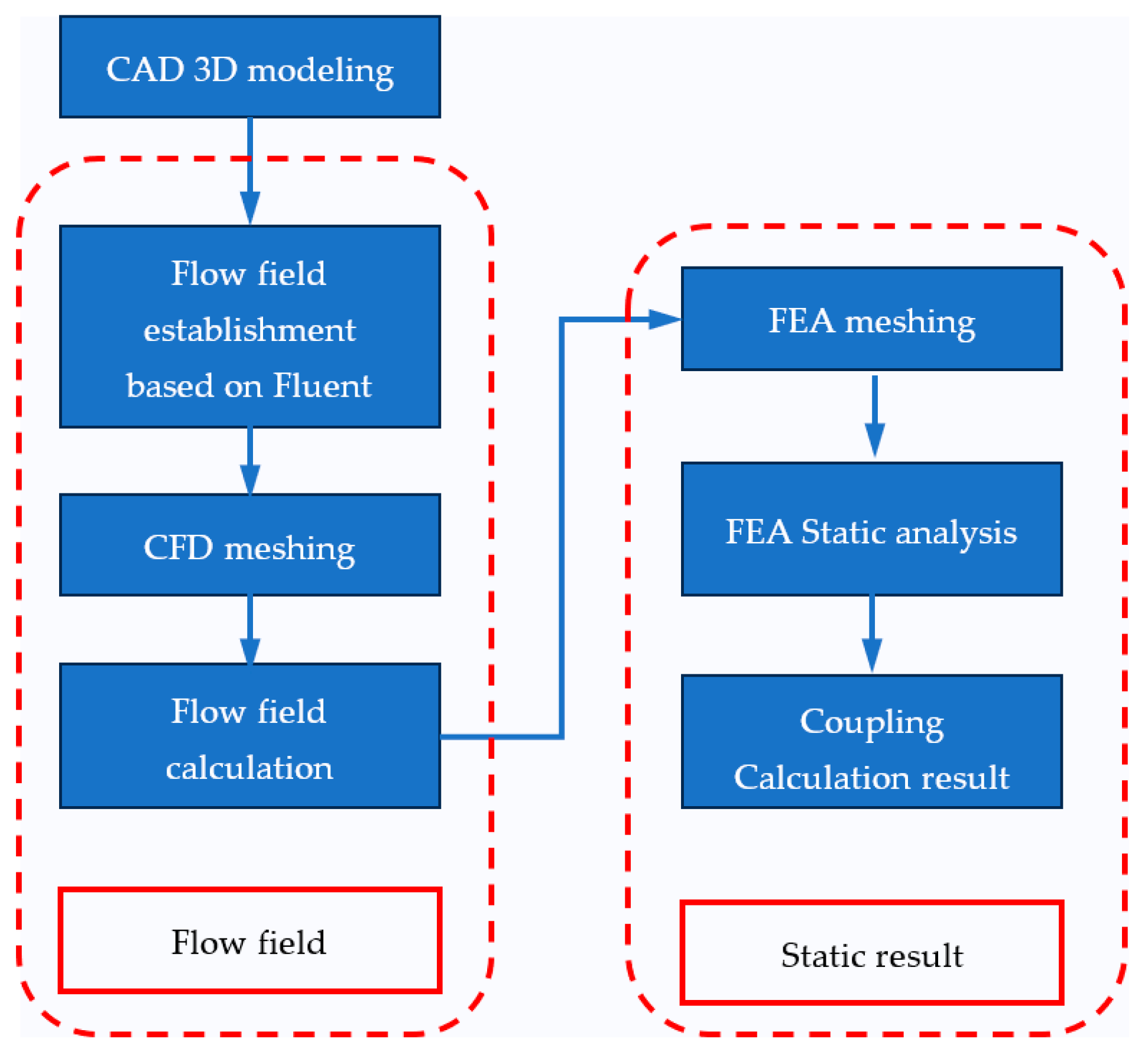
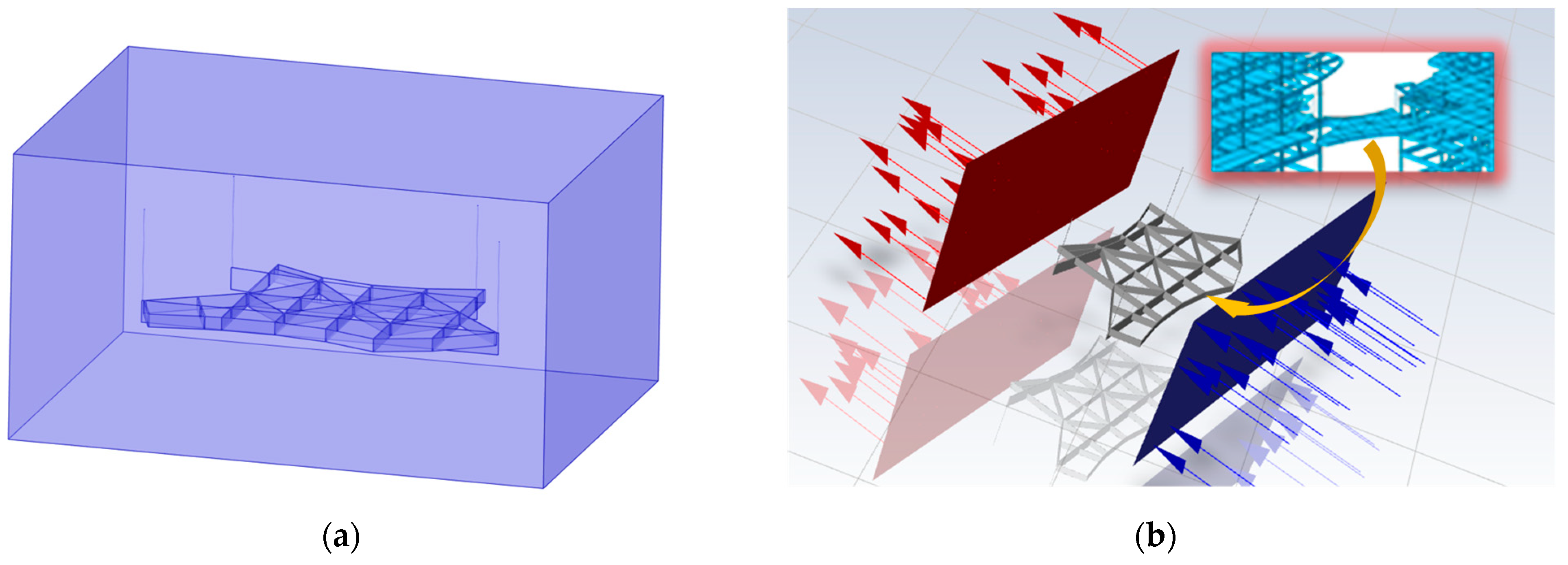
3.1. Fluid-Structure Coupling Method

The modeling and numerical simulation of fluid-structure coupling are important for improving product performance, ensuring structural safety, and predicting and maintaining system stability. In a broad sense, the interaction between wind and structure can be summarized as a fluid-structure coupling problem [14]. According to the coupling mechanism, the fluid-structure coupling problem can be divided into two categories: the first type is that the two phase domains partially or completely overlap, which makes it difficult to distinguish them obviously, so the constitutive equation needs to be established for specific physical phenomena, and the coupling effect is reflected by the differential equation describing the problem [15]. The second type is that the coupling effect only occurs at the interface of two phases, and the coupling effect is introduced into the balance and coordination relationship of the two phase coupling surfaces through the equation. The first type of problem is characterized by the two phase domains partially or completely overlapping so that the constitutive equation needs to be established for specific physical phenomena, while the second type of problem is characterized by the coupling effect only occurring at the interface of two phases and its coupling effect bring realized by introducing the balance and coordination relationship of the two phase coupling surfaces into the equation. Therefore, in order to further study the interaction between wind and structure, this paper adopts the coupling method based on fixed mesh technology, namely the immersion boundary method [16], to analyze the wind load effect of high-altitude small-spacing steel-structure connecting bridge in the hoisting stage in order to provide theoretical guidance for the construction safety of the field sling construction process under the influence of wind load. Specifically, this paper first establishes the fluid-structure coupling model considering the wind load effect and uses the immersion boundary method to solve the model, obtain the deformation, stress, and support reaction parameters of the steel structure connecting bridge under wind load effects in the hoisting stage, and provide a reference for the site construction safety.
This paper studies the second major type of coupling problem, that is, the coupling of structure and fluid only occurring on the contact surface. The Fluent module and Static Structural module in the finite element software ANSYS Fluent 2022 R1 are used for data exchange modeling. The structures will deform when they are subjected to pressure on the surface. For the movement of fluids, the solid structure in the deformation process will in turn produce a specific effect [17]. The analysis method of unidirectional fluid-structure coupling can be used to study the effect of flow field under the instantaneous change of airflow, that is, when two physical fields are solved in a certain order, and then the results on the boundary of the two physical fields are applied to one physical field as boundary conditions, and another physical field is solved iteratively. The specific coupling process is shown in Figure 5. After the establishment of the geometric model, the Fluent module is used to determine the flow field model and divide the grid. After that, the calculation and analysis of the flow field are carried out to obtain the specific distribution data of the flow field. The fluid pressure on the surface of the coupling between the flow field and the structure is transformed into the static external load of the solid, and the solid is meshed and analyzed in the Static Structure calculation module to obtain the stress distribution and displacement analysis of the structure under the impact of the fluid transient flow.

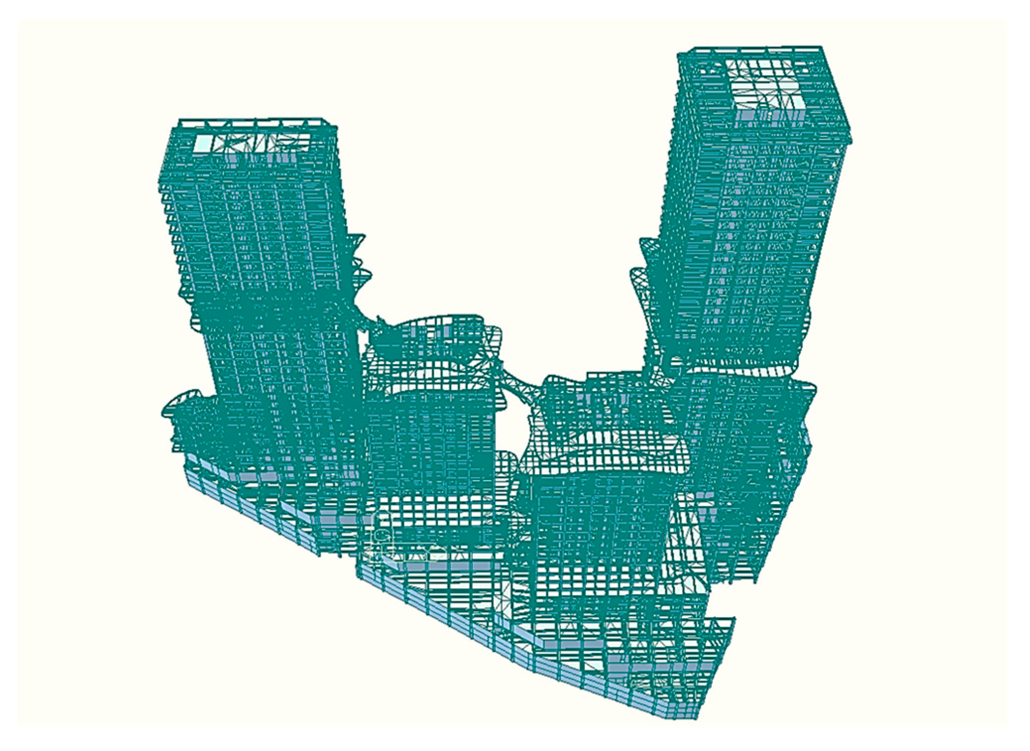
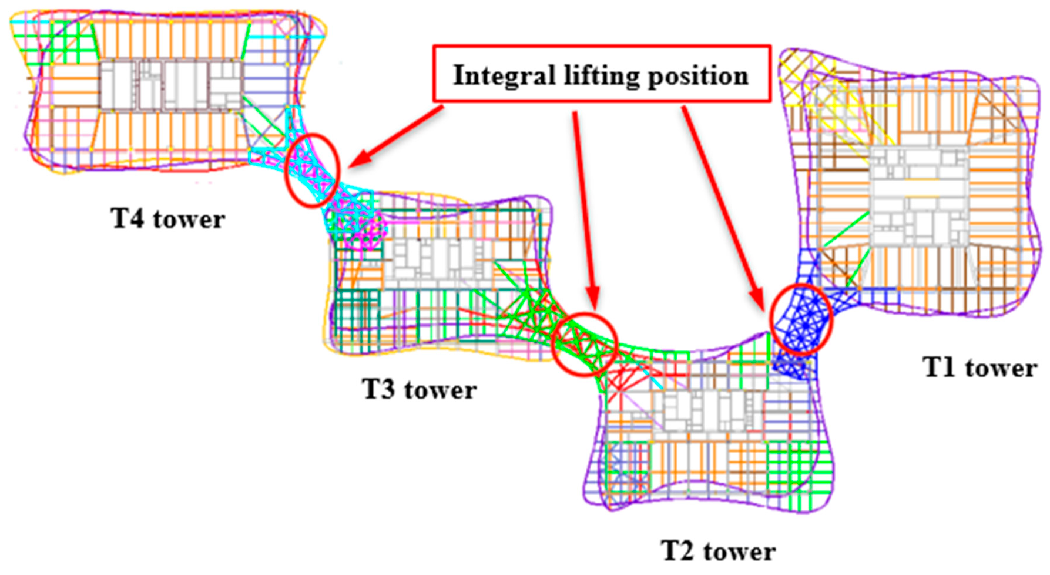
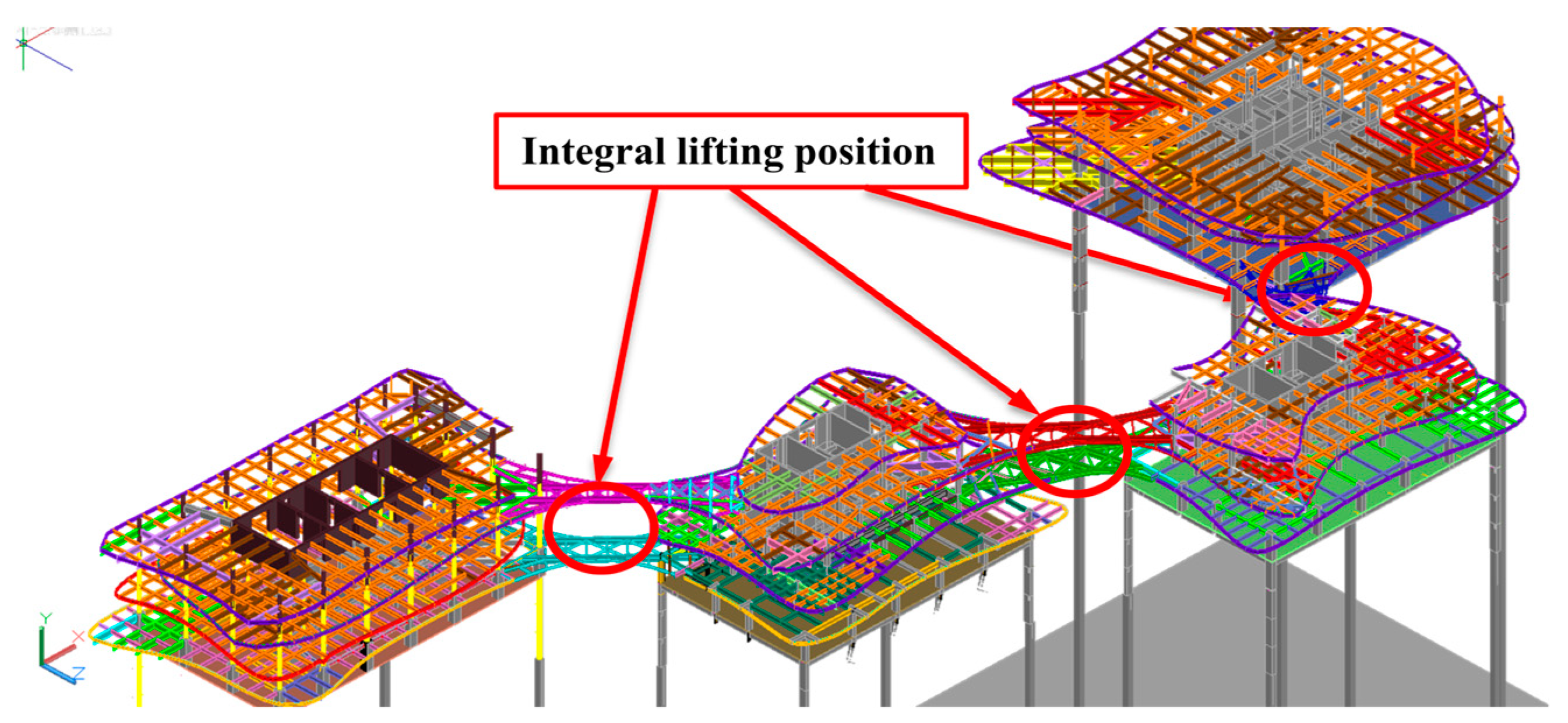
3.2. Establishment of the Geometric Model

Because the actual structure and nodes of the elevated three-zone steel structure connecting bridge are relatively complex, and the main goal of our modeling is sto explore the influence of wind load on the lifting processes [18,19]. The solid-steel structure model is simplified by using a rectangular section. Four anchor points are set with equal height slings, and fixed constraints are set on the top surface of the slings [20].

3.3. Setting of the Flow Field

The division of the fluid field is shown in Figure 6a, which is a rectangular body. One side is set as the air inlet (blue), one side is set as the air outlet (red), and the other four sides are closed walls. Taking into account the influence of the structure around the steel-structure connecting bridge on the flow field, the angular direction of the air inlet is adjusted according to the design drawings. The whole working condition is shown in Figure 6b, the blue side of the rectangular body is the air outlet, and the red side is the air inlet. The air speed of the air inlet is set to two working conditions, which are 5 m/s and 10 m/s, respectively. The air density is set to 1.225 kg/m3, and the viscosity is set to 1.789 × 10⁻⁵ kg/(m × s). The whole flow field is calculated by using a diffuse smooth dynamic grid.

3.4. Mesh Division

The built-in mesh separator in the software is used to divide the grids of the fluid, solid, and fluid-solid interface, respectively. The network cannot be divided too densely or too sparsely. If it is too dense, it will affect the calculation efficiency, and if it is too sparse, there will be a large error with the real situation, and the flow field calculation may not converge. In the software, the adaptive algorithm is used to automatically encrypt the grid at the fine points of the model. The total number of units divided is 849,616, and the total number of nodes is 150,286. After the inspection of the grid quality coefficient [21] is above 0.9, the next operation can be carried out. Table 1 gives the mechanical performance index of the steel used in the solid structure of the steel structure used in the modeling, and Table 2 gives the statistical number of grid units. The fluid loaded onto the solid-structure grid will produce pressure on the solid, that is, aerodynamic load. The key to the so-called unidirectional fluid-structure coupling is to obtain the pressure brought by the fluid to the solid through calculation, so as to treat it as the external load applied to the solid for static calculation. According to the calculation results of the software, in the case of 5 m/s, the maximum wind pressure applied to the solid structure is 17.858 Pa, and the maximum negative wind pressure is 52.512 Pa. In the case of 10 m/s, the maximum wind pressure applied to the solid structure is 67.601 Pa, and the maximum negative wind pressure is 177.440 Pa. It can be seen that the maximum wind pressure increases faster than the wind speed. However, in the case of increasing wind speed, the maximum wind pressure only occurs in several sags of the structure, and the overall partial pressure distribution is roughly between 50 Pa and −100 Pa.

4. Flow Field Calculation Results and Analysis

Figure 7a is the velocity amplitude distribution diagram of the inlet wind speed of 5 m/s. It can be seen that the velocity of the fluid is relatively stable and there is no turbulence phenomenon. Because the solid structure has a small windward area in the horizontal direction and a low wind speed, the wind speed is reduced only near the outlet of the connecting bridge accessory, and the wind speed of other regions is generally maintained with a uniform distribution. The maximum wind speed in the figure is 7.64 m/s, which appears at the plane of the outlet. Figure 7b is the distribution diagram of the total wind pressure of the inlet wind speed of 5 m/s. It can be seen that the distribution of wind pressure is also relatively regular. The wind pressure in the fluid area, which is 22 Pa, is basically consistent. From the side and the other side of the connecting bridge near the outlet, the wind pressure is positive, while at the connecting bridge’s belly bar structure, the wind pressure is negative; that is to say, these places are air shadow areas, and these areas are subject to the suction of the wind. The cantilever beam on the windward side bears the maximum positive wind pressure, and the wind pressure at the adjacent node with a relatively large span is also relatively large. After the main beam near the outlet bears a large wind pressure, the inner belly bar bears a large negative pressure, which is suction. The maximum positive wind pressure in the figure is 22 Pa, and the maximum negative wind pressure is 18.2 Pa. It can be seen that in the case of 5 m/s wind speed, the wind speed and wind pressure field maintain a relatively stable distribution. Figure 7c is the velocity amplitude distribution diagram with the inlet wind speed of 10 m/s, which is similar to the fluid velocity distribution with the wind speed of 5 m/s; however, the amplitude of the fluid velocity is notably larger. Figure 7d is the total wind pressure distribution diagram with the inlet wind speed of 10 m/s. It can be seen that compared with the wind speed of 5 m/s, the amplitude has changed greatly. The maximum positive wind pressure in the figure is 182 Pa, and the maximum negative wind pressure is 44.1 Pa. It can be seen that in the case of increasing wind speed, the maximum wind pressure occurs at the corner position of the steel structure bridge, and the overall wind pressure distribution is not uniform at low wind speed, which makes it easy to produce local turbulence.

5. Static Calculation Results and Analysis of the Steel Structure Bridge

The purpose of static analysis is to determine the stress state of each component inside the structure and the interaction relationship between each component. After the pressure field obtained by fluid analysis [22] is applied to the fluid-structure coupling surface, the four slings on the solid structure are fixed and a standard gravity is applied to the whole structure, the static calculation of the solid structure can be carried out, and the total deformation distribution diagram under two wind speeds is obtained. The equivalent stress distribution diagram is shown in Figure 8.
Now, the deformation analysis shows that at a wind speed of 5 m/s, the maximum deformation of the bridge structure reaches 15.141 mm. It can be seen from Figure 8a that the four slings have obvious deformation, indicating that the hoisting structure will still produce a considerable degree of deformation even under a small wind speed. This also shows the sensitivity of the hoisting structure to wind load. In addition, it can be seen that the position of the maximum deformation is the position where the steel structure bridge is closest to the outlet. It can be seen from Figure 8c that under the wind speed of 10 m/s, the maximum deformation of the connecting bridge structure reaches 28.970 mm. Compared with the condition of lower wind speed, the deformation distribution of the bridge structure does not change much, but the deformation amplitude increases.
Now, considering the equivalent stress distribution, at a wind speed of 5 m/s, the maximum equal effect force in Figure 8b reaches 45.224 Mpa, but the maximum stress is only reached in several local areas. The equivalent stress of most of the connecting bridge structures is in a low degree, within the safe range of steel strength. Compared with deformation, the stress distribution of the structure is more uniform and is mainly controlled by gravity. At a wind speed of 10 m/s, the maximum equal-effect force in Figure 8d reaches 102.700 Mpa. Compared with a lower wind speed, the stress distribution of the structure does not change much.

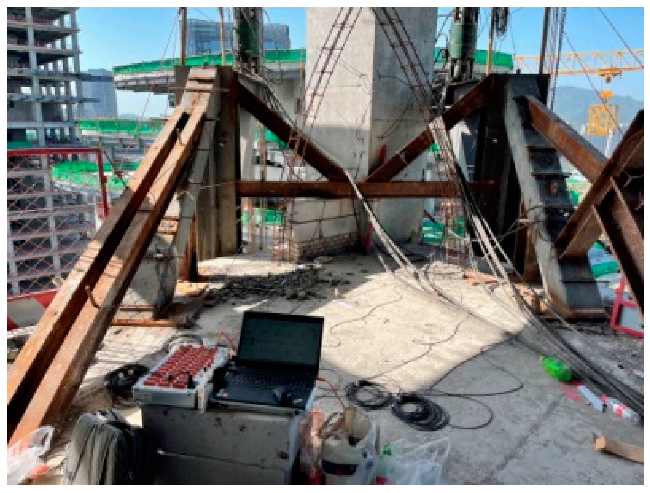
6. High-Altitude Steel Connecting Structure Overall Lifting Construction Monitoring
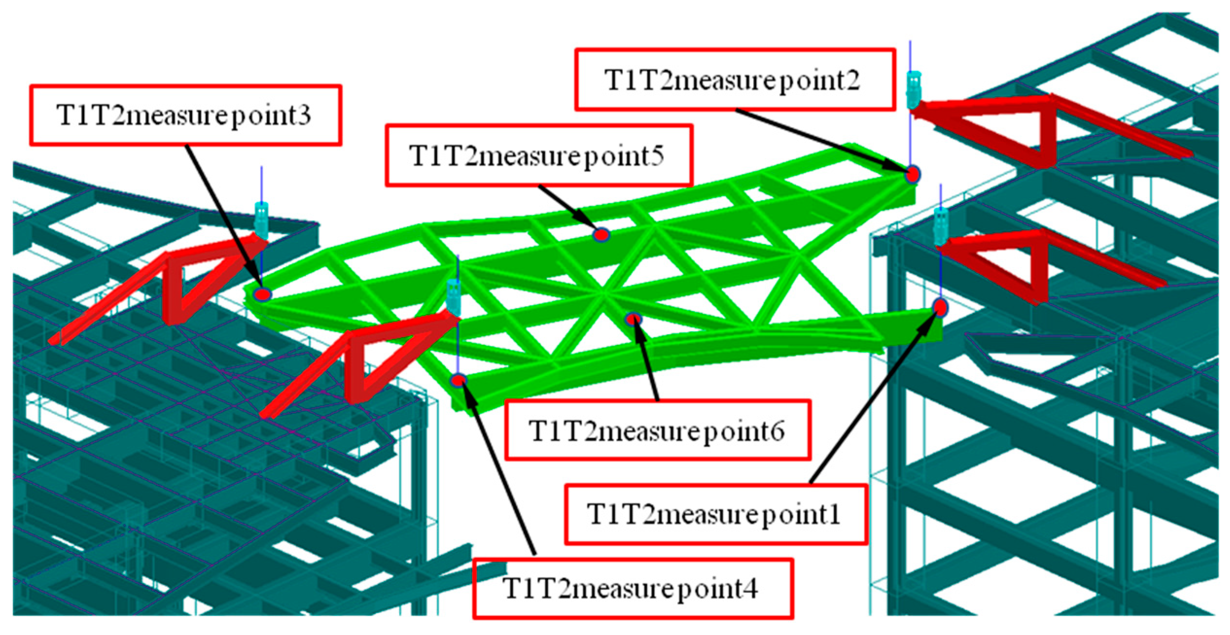
6.1. General Idea

Construction monitoring refers to the technical means by which monitoring instruments are used to monitor the control indicators of key parts during the construction of structures under construction, and alarms are issued when the monitoring value is close to the control value, which is used to ensure the safety of construction and can also be used to check whether the construction process is reasonable.
The overall lifting process of the high-altitude connected steel structure of this project needs to be monitored throughout the construction process, which mainly includes whether the stress and strain changes of the structural members of the steel-connected bridge are within the safety limit during the lifting process. We aim to determine if the steel components of the bull leg used to support the hydraulic cylinder and the lifting point at the lifting platform are safe [23,24].
According to the requirements of the monitoring content, in order to ensure the safety of the overall upgrading process of the steel-connected bridge, a detailed monitoring plan has been formulated. Since the arrangement of measuring points in the three lifting zones is similar, the T1–T2 zone is taken as an example.
The T1–T2 zone is a one-layer steel bridge, and there are no I-beam members for temporary connection on the raised bridge. During the lifting, six measuring points were arranged on the connecting bridge to be lifted, one measuring point was arranged on the main longitudinal beam of the steel connecting bridge, one measuring point was arranged on the beam of the connecting bridge, and the other four measuring points were arranged on the members of the lower lifting point, as shown in Figure 9. In Figure 9, measuring point 5 is arranged on the lower surface of the beam, that is, the compression side, and measuring point 6 is arranged on the lower surface of the beam, that is, the tension side.

6.2. T1–T2 Steel Connected Bridge Overall Pre-Lifting Monitoring Data Analysis

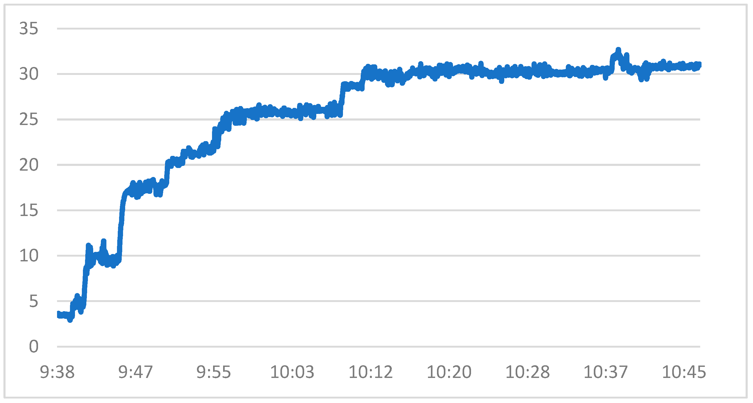
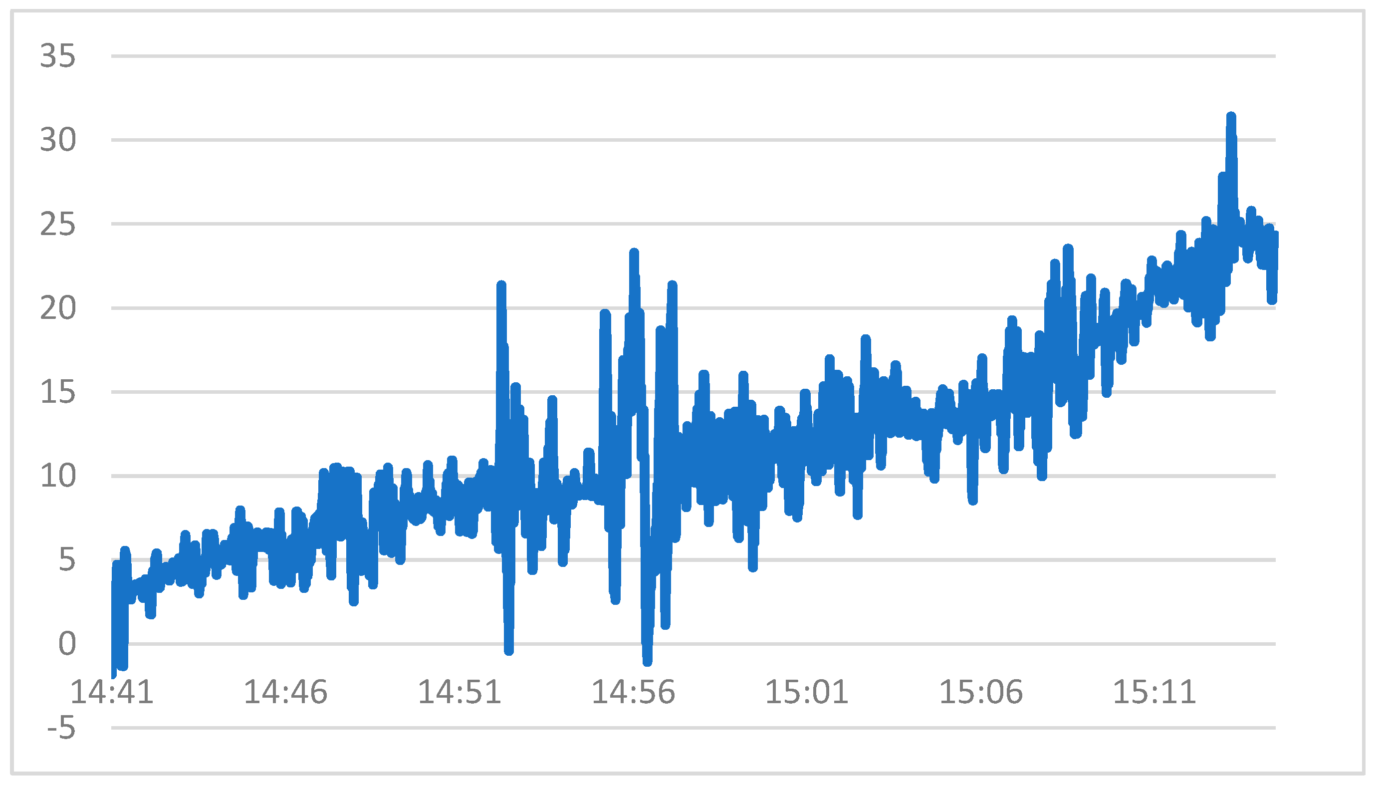
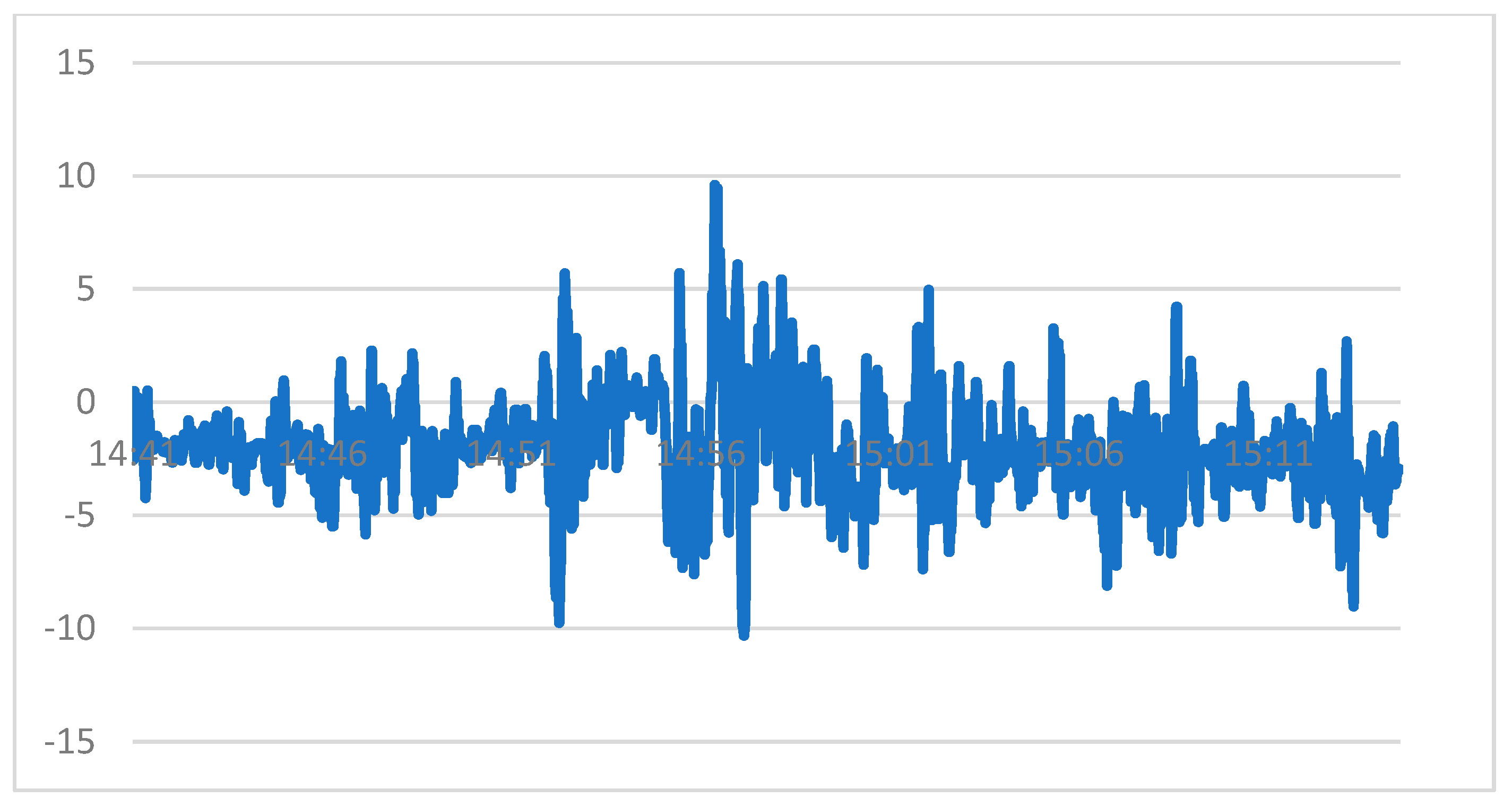
6.2.1. Strain Change Data Analysis of the Elevated Bridge Measuring Point in the First Pre-Lifting Stage

Through the installation of sensors and monitoring equipment, real-time stress and strain monitoring of the steel bridge was carried out to determine whether there were problems such as structural safety and external load influence in the construction process and provide technical support for the construction safety of the steel structure. There were six measuring points on the elevated bridge of the T1–T2 zone. Due to space limitation, the strain changes of the two measuring points 1 and 5 during the whole pre-lifting process are given here. These two measuring points represent the stress conditions of the longitudinal main beam of the bridge and the lifting point under the bridge, respectively.
Figure 10 and Figure 11, respectively, give the curves of the whole process of strain change of measuring point 1 and measuring point 5. It can be seen that during the first lifting process, measuring point 1 is subjected to tensile force and gradually becomes larger, while measuring point 5 changes abruptly from positive to negative at around 10:00, indicating that a certain bending moment of the main beam is generated at this time, resulting in compressive stress at the measuring point.
Compared with the yield strain of steel, the safety redundancy is high, and the first lifting process is safe enough for the bridge to be lifted and the lower lifting point.

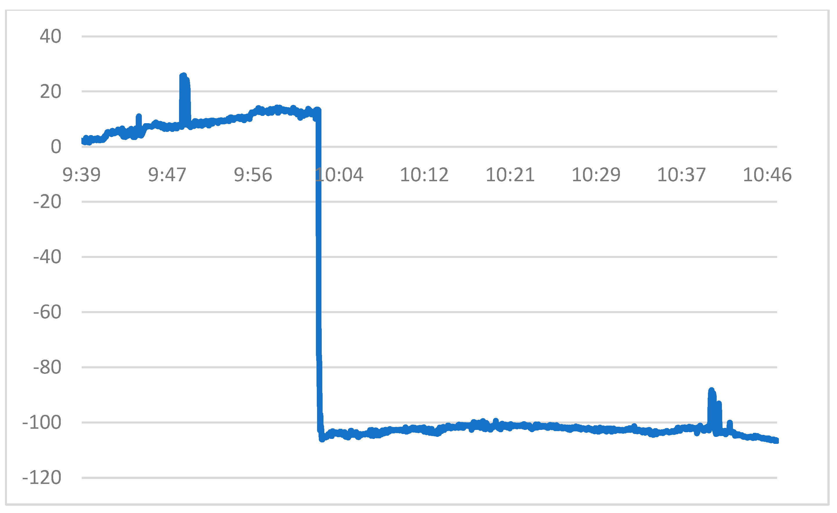
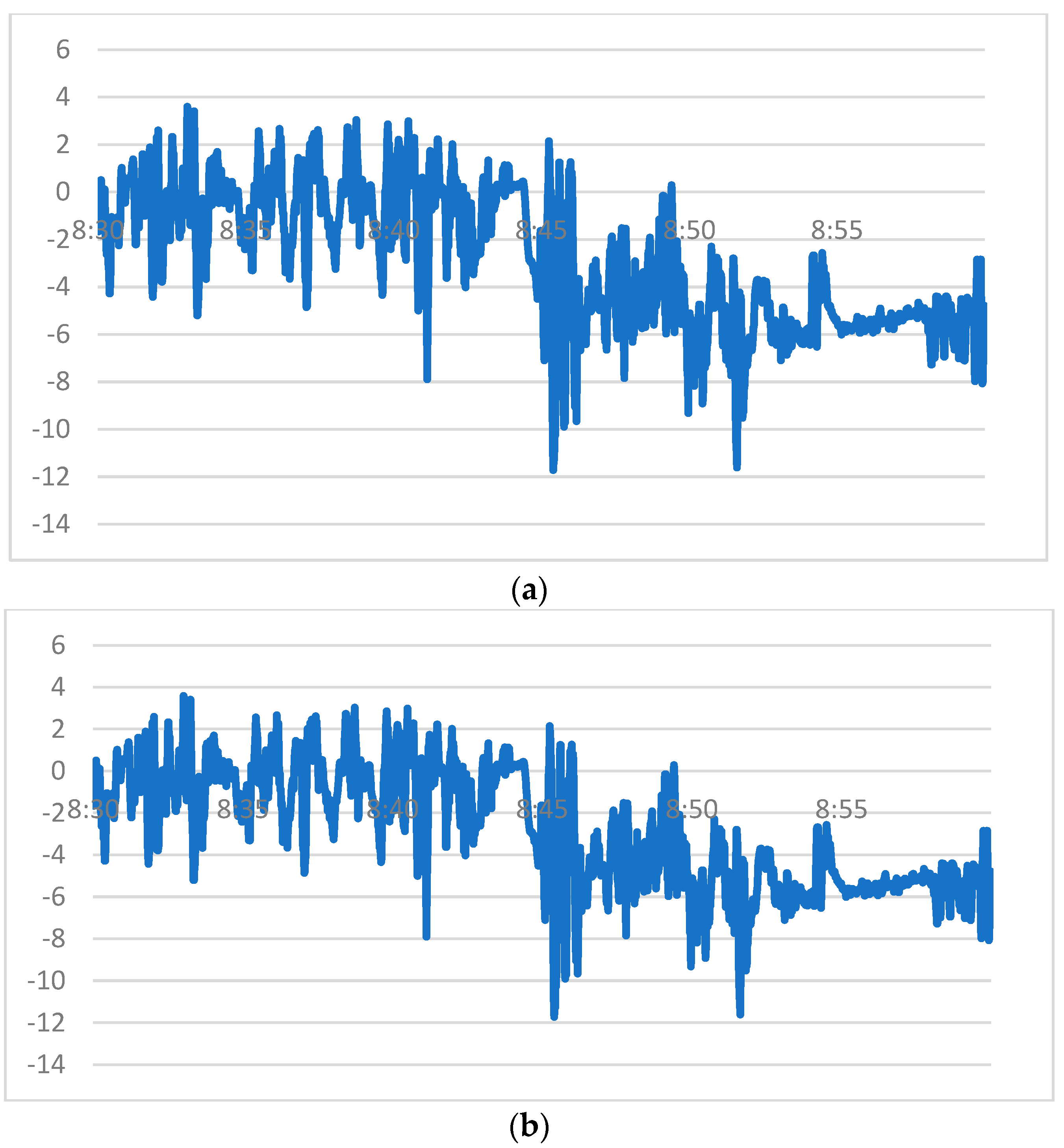
6.2.2. Analysis of Strain Change Data of the Elevated Bridge Measurement Point in the Second Pre-Lifting Stage

During the second pre-lifting, the damper weighing about five tons was tied to the bridge, and the force and deformation of the bridge itself, the upper and lower lifting point, and the bull leg were completed. In addition, the weight of the damper was relatively small compared to the bridge. Therefore, the monitoring data of the second pre-lifting at this time did not show a sudden force change; we mainly observed whether the lifting process was stable.
Similarly, the whole-process change curves of strain change at test points 1 and 5 are shown here, as shown in Figure 12 and Figure 13. The variation pattern is similar to the above.

6.3. T1–T2 Steel Bridge Overall Upgrade Monitoring and Data Analysis

The monitoring personnel monitored the whole process of the formal lifting construction process of the T1–T2 bridge, and the data were complete and good. The whole lifting process was relatively stable, the influence of the external environment was lower, and the lifting process was smooth, achieving the purpose of on-site monitoring. Figure 14 shows the monitoring site photos of the monitoring personnel during the whole process of formal upgrading.
For the bridge to be lifted, after the end of the pre-lifting stage, its force has to have been relatively stable, and when formally lifting, it is mainly necessary to pay attention to the stability of the lifting process and the influence of the external environment.
During formal lifting, there is no sudden change in the force during pre-lifting, and the force change of each component of the bridge to be lifted will not be too great. At this time, the purpose of construction monitoring is mainly to observe the stability of the steel bridge during lifting and the influence of the external environment, such as short-term wind gusts, on the lifting process. If the stroke of the four hydraulic devices is stable during lifting, and the external wind load and other influences are small, Theoretically, the strain change of the above measuring points will be small.
Since the monitoring time is long and the data acquisition frequency is 1 Hz, the total amount of data at each measuring point is about 21,600. For simplicity, two periods of 8:30–9:00 and 14:00–14:30 are selected here to describe the strain changes at each measuring point.
According to the monitoring data, in each time period, the strain change of each measuring point is relatively gentle, and the strain value is small, indicating that the lifting process is relatively stable, the external environment has little influence, and the formal lifting is safe for the bridge structure to be lifted.
It is worth noting that, as shown in Figure 15 and Figure 16, the data of measurement point 1 and measurement point 5 has a small mutation in the time periods of 8:30–9:00 and 14:00–14:30, which indicates that at this stage, the force of the rod where the measurement point is located is affected by the instability of lifting, but the mutation value is not large and decreases rapidly. This shows that the company lifting the steel-connected bridge has adjusted for unstable situations, and the force of the component is more reasonable.
Figure 15 and Figure 16 show the strain change curves of measuring points 1 and 5 at 8:30–9:00 and 14:00–14:30, respectively. The change rules of other measuring points and time periods are similar.

7. Conclusions

In this paper, a unidirectional fluid-structure coupling model was established to simulate the steel structure construction under wind load in lifting zone 3 of the Zhuhai Tiejian Square Project. The results showed that when the wind speed is 5 m/s or 10 m/s, the lifting structure still produces a certain deformation. The calculation results show that the sensitivity of the lifting structure under wind load and the stress calculation results are still within the safe range of steel strength. With the increase of wind speed, the local maximum stress of the structure increases greatly, but the overall deformation remains stable, which indicates that the greatest challenge of hoisting steel structures under wind load may be the stability direction rather than the strength, so it is necessary to strictly monitor the displacement deformation of the structure during construction.
In the overall lifting process of the steel structure, it is necessary to arrange the measuring points according to the results of numerical simulation and mechanical analysis. It is necessary to pay special attention to the temporary reinforcement plates, I-steel connectors, temporary columns, etc., and observe the stress changes of the measuring points on these components at all times. To ensure the safety of the whole process of lifting, it is very important to monitor the whole process of pre-lifting. In the pre-lifting process, the bridge to be lifted, the upper and lower lifting points, the bull legs, and the temporary reinforcement parts will undergo stress transformation, resulting in a large stress-strain mutation. If the data in the pre-lifting process is in a safe state, the subsequent formal lifting will generally be safe. The whole process monitoring of the formal lifting process is mainly to prevent the excessive instability of the lifting process and the influence of external environmental factors (such as short-term wind gusts and getting stuck in the middle). In the formal lifting process, the strain data of all measuring points have little change.
Through fluid-structure coupling calculation and real-time monitoring data analysis, it was shown that the lifting process of Zhuhai Tiejian Square high-altitude steel connecting bridge is safe and reliable, the force transformation of each component was reasonable, the lifting process was relatively stable, the external environment had little influence, and the expected monitoring effect was achieved. The calculation simulation and on-site monitoring in this paper can provide theoretical and practical guidance for construction safety under the influence of wind load in the construction process of the sling and provide an important reference value for the same type of project.

Author Contributions

The authors confirm the following contributions to this paper: study conception and design: X.W., S.C. and Z.W.; data collection: S.C., Y.H., Z.L. and Z.W.; analysis and interpretation of results: X.W., Z.W. and S.C.; draft manuscript preparation: X.W., Z.W., S.C., Z.L. and Y.H. All authors have read and agreed to the published version of the manuscript.

Funding

This research was funded by the Open Fund Project of the Transportation Infrastructure Intelligent Management and Maintenance Engineering Technology Center of Xiamen City (Grant No. TCIMI201803) and the Project of the 2011 Collaborative Innovation Center of Fujian Province (Grant No. 2016BJC019), Supported by the Fundamental Research Funds for the Central Universities (Grant No. 20720232002).

Data Availability Statement

The original contributions presented in the study are included in the article, further inquiries can be directed to the corresponding author.

Acknowledgments

Open-access funding was provided and organized by the Xiamen Transportation Infrastructure Intelligent Management and Maintenance Engineering Technology Research Center. The authors gratefully acknowledge the support.

Conflicts of Interest

Author Yixin Hu was employed by the company China Communications (Fuzhou) Construction Co., Ltd. The remaining authors declare that the research was conducted in the absence of any commercial or financial relationships that could be construed as a potential conflict of interest.

References

  1. Zhang, B. Study on construction technology and wind invasion assessment of steel super high-rise buildings in coastal strong wind environment. Adhesion 2023, 50, 172–177. [Google Scholar]
  2. Zhu, Q.; Hu, X.; Han, Z.; Ma, R. Research on the wind load effect of the combined system of steel bridge tower and crane. Shanghai Highw. 2022, 2, 26–29+84+165. [Google Scholar]
  3. Liu, Q.; Zhang, M.; Wang, Y.; Zhu, X. Analysis of equivalent wind load in the construction stage of high-rise buildings. Build. Struct. 2021, 51, 1763–1769. [Google Scholar]
  4. Jia, Y.; Hao, Y. Wind vibration response analysis of high-rise steel structure. Rural Econ. Technol. 2020, 31, 392–393. [Google Scholar]
  5. Zhang, Q. Design analysis of high-rise building structure under wind load. Real Estate Guide. 2020, 52–53. [Google Scholar]
  6. Long, X.; Mao, M.; Su, T.; Su, Y.; Tian, M. Machine learning method to predict the dynamic compressive response of concrete-like material at high strain rates. Def. Technol. 2020, 23, 100–111. [Google Scholar] [CrossRef]
  7. Su, Y.; Wang, J.; Li, D.; Wang, X.; Hu, L.; Yao, Y.; Kang, Y. End-to-end deep learning model for underground utility localization using GPR. Autom. Constr. 2023, 149, 104776. [Google Scholar] [CrossRef]
  8. Chen, F.; Zhang, H.; Li, Z.; Luo, Y.; Xiao, X.; Liu, Y. Residual stresses effects on fatigue crack growth behavior of rib-to-deck double-sided welded joints in orthotropic steel decks. Adv. Struct. Eng. 2023, 27, 35–50. [Google Scholar] [CrossRef]
  9. Zhang, C. The active rotary inertia driver system for flutter vibration control of bridges and various promising applications. Sci. China Technol. Sci. 2023, 66, 390–405. [Google Scholar] [CrossRef]
  10. Yang, L.; Ye, M.; Huang, Y.; Dong, J. Study on Mechanical Properties of Displacement-Amplified Mild Steel Bar Joint Damper. Iran. J. Sci. Technol. Trans. Civ. Eng. 2023. [Google Scholar] [CrossRef]
  11. Liang, F.; Wang, R.; Pang, Q.; Hu, Z. Design and optimization of press slider with steel-aluminum composite bionic sandwich structure for energy saving. J. Clean. Prod. 2023, 428, 139341. [Google Scholar] [CrossRef]
  12. Wei, W.; Cheng, C. Integral lifting technology of long-span connected steel structure. Constr. Technol. 2009, 38, 43–45. [Google Scholar]
  13. GB50017-2017; Industrial standards of the People’s Republic of China. Code for Design of Steel Structure. China Architecture and Building Press: Beijing, China, 2017.
  14. Yu, B.; Zhu, X.; Li, D.; Liu, C.; Zhao, Z. Analysis of vehicle body deformation in electrophoresis process based on fluid-structure coupling. Comput. Aided Eng. 2022, 31, 34–38. [Google Scholar]
  15. Liu, Z.; Li, X.; Yan, J. Vibration characteristics analysis of fixed-free riser based on three-dimensional numerical simulation of fluid-structure coupling. Min. Res. Dev. 2022, 42, 172–176. [Google Scholar]
  16. Zhang, G.; Wang, S.; Sun, Z.; Xiao, Q. Research progress of fluid-structure coupling numerical methods in ship and ocean engineering. China Ship Res. 2022, 17, 1–22. [Google Scholar]
  17. Liu, D. Monitoring research on unloading construction process of long-span curved mesh structure. Constr. Technol. 2022, 51, 97–99+103. [Google Scholar]
  18. Zhang, H.; Zhang, W.; Zhang, Q.; Pei, Y. Digital simulation analysis of construction scheme for long-span steel structure. Eng. Constr. Des. 2022, 129–131. [Google Scholar]
  19. Yu, G. Research on key issues in construction process of steel truss beam of xiaogera suspension bridge. Chang. Univ. Sci. Technol. 2016. [Google Scholar]
  20. Sun, F.; Zhu, D.; Zhang, D. Research on de-escalation model of fluid-structure coupling calculation for wind turbine blade. J. Vib. Shock 2021, 40, 175–181+215. [Google Scholar]
  21. Chen, F.; Tang, B.; Cai, Q.; Li, Q. Research on wind load characteristics and wind pressure prediction of long-span flat roof. J. Vib. Shock 2021, 40, 226–232. [Google Scholar]
  22. Zheng, D.; Liu, S.; Gu, M.; Quan, Y.; Pan, J.; Zhou, J. Numerical Simulation of wind load on long-span hollow-out grid roof. J. Zhengzhou Univ. 2021, 42, 93–98. [Google Scholar]
  23. Wang, D.; Li, Y.; Liu, Y.; Shi, S. Analysis of Key Techniques in hoisting construction of large-span complex Steel Structures. Eng. Constr. 2020, 34, 1173–1175. [Google Scholar]
  24. Sun, G.; Zhu, Q.; Wu, W. Monitoring and analysis of pushing construction of open steel box girder with hill-shaped section. Constr. Tech. 2018, 47, 117–123. [Google Scholar]
Figure 1. Zhuhai Tiejian Square effect diagram.
Buildings 14 01755 g001
Figure 2. Zhuhai Tiejian Square overall modeling axonometric.
Buildings 14 01755 g002
Figure 3. Plane position diagram of each steel bridge.
Buildings 14 01755 g003
Figure 4. Three-dimensional position diagram of each steel bridge.
Buildings 14 01755 g004
Figure 5. Flow chart of the unidirectional fluid-solid coupling.
Buildings 14 01755 g005
Figure 6. Geometric model establishment. (a) Fluid domain partition diagram (b) Simulated operating diagram.
Buildings 14 01755 g006
Figure 7. Velocity amplitude and total flow pressure distribution diagram. (a) Velocity amplitude (m.s−1) (Wind speed: 5 m/s) (b) Total flow pressure (Pa) (Wind speed: 5 m/s). (c) Velocity amplitude (m.s−1) (Wind speed: 10 m/s) (d) Total flow pressure (Pa) (Wind speed: 10 m/s).
Buildings 14 01755 g007
Figure 8. Fluid-structure coupling calculation results. (a) Total deformation distribution (mm) (wind speed: 5 m/s) (b) Equivalent stress distribution (Pa) (wind speed: 5 m/s). (c) Total deformation distribution (mm) (wind speed: 10 m/s). (d) Equivalent stress distribution (Pa) (wind speed: 10 m/s).
Buildings 14 01755 g008
Figure 9. Schematic diagram of measuring point layout of the elevated bridge.
Buildings 14 01755 g009
Figure 10. Strain change curve of measuring point 1 during the first pre-lifting. (Vertical axis unit: ×10−6).
Buildings 14 01755 g010
Figure 11. Strain change curve of measuring point 5 during the first pre-lifting. (Vertical axis unit: ×10−6).
Buildings 14 01755 g011
Figure 12. Strain change curve of measuring point 1 during the second pre-lifting. (Vertical axis unit: ×10−6).
Buildings 14 01755 g012
Figure 13. Strain change curve of measuring point 5 during the second pre-lifting. (Vertical axis unit: ×10−6).
Buildings 14 01755 g013
Figure 14. Officially upgraded field monitoring.
Buildings 14 01755 g014
Figure 15. Strain change curve of measuring point 1 during formal lifting. (a) 8:30–9:00 (Vertical axis unit: ×10−6) (b) 14:00–14:30 (Vertical axis unit: ×10−6).
Buildings 14 01755 g015
Figure 16. Strain change curve of measuring point 5 during formal lifting. (a) 8:30–9:00 (Vertical axis unit: ×10−6) (b) 14:00–14:30 (Vertical axis unit: ×10−6).
Buildings 14 01755 g016
Table 1. Mechanical performance index of steel.
Table of MaterialsQ355B
Bulk density (kN·m−3)76.98
Tensile strength (N·mm−2)470
Yield strength (N·mm−2)355
Modulus of elasticity (kN·mm−2)206
Table 2. Model unit statistics.
Unit NumberNo. of NodesUnit Size
849,616150,2860.5 m
Disclaimer/Publisher’s Note: The statements, opinions and data contained in all publications are solely those of the individual author(s) and contributor(s) and not of MDPI and/or the editor(s). MDPI and/or the editor(s) disclaim responsibility for any injury to people or property resulting from any ideas, methods, instructions or products referred to in the content.

