Article

Critical Face Pressure of a Tunnel Driven by a Shield Machine Considering Seismic Forces and Tunnel Shape Influence

1
Xinjiang Water Conservancy and Hydropower, Survey and Design Institute Co., Ltd., Urumqi 830000, China
2
Xinjiang Shuifa Construction Group Co., Ltd., Urumqi 830000, China
3
Faculty of Engineering, China University of Geosciences, Wuhan 430074, China
*
Author to whom correspondence should be addressed.
Buildings 2024, 14(6), 1760; https://doi.org/10.3390/buildings14061760
Submission received: 16 April 2024 / Revised: 27 May 2024 / Accepted: 31 May 2024 / Published: 11 June 2024

Abstract

:
Evaluating critical face pressure with high accuracy is an important topic for shield tunneling. The existing research focuses more on the influence of complex geological conditions or environmental factors, and there are few reports on the influence of tunnel shape on critical face pressure. In reality, the tunnel shape has a significant impact on the deformation zone in front of the tunnel face, which may lead to non-negligible differences in shield pressure. To fill this gap, an efficient analytical approach is proposed to estimate the critical face pressure considering different tunnel shapes in the framework of limit analysis. As earthquakes are potential threats to the tunnel face stability in seismically active regions, the seismic effect is also taken into account with the help of the pseudo-static method. Several cases with the same area but different tunnel shapes are investigated using the limit analysis method. A comparison with static analysis is given to highlight the influence of seismic forces on the tunnel face stability. The results show that the critical face pressures increase by 15.3% when the tunnel face shape changes from rectangular to circular, and by 23.5% when the horizontal seismic coefficient varies from 0 to 0.1. A further validation with a 3D finite difference method is performed with respect to four typical tunnel shapes considered in this study. Lastly, several stability charts are provided for a quick estimation of the critical tunnel face pressure subjected to seismic forces. It is concluded that the proposed method can be applied to a tunnel stability assessment of various cross-sections and is highly efficient compared with numerical simulations.

1. Introduction

Since the beginning of humankind’s exploration of underground space, the stability of the digging face and surrounding soil mass has become an interesting topic in the field of geotechnical engineering. Currently, the most commonly used theoretical methods for the tunnel face stability assessment mainly include the limit analysis method and limit equilibrium method [1,2,3,4]. In addition, numerical approaches, such as finite element or finite difference methods, are increasingly used to study the safety and stability of underground work face during the excavation process [5,6,7]. In the existing literature, the cross-sectional shape of a tunnel is usually simplified into a circular or rectangular one under the principle of equal area. The circular or rectangular shape is usually chosen to construct the failure mechanism of the tunnel face due to its simplicity. In practical tunnel design, rectangular tunnels are not advisable for underground excavations due to their significant stress concentration at the corners, and the circular tunnel shape is only common when tunnels are excavated using a tunneling boring machine.
As a result, a more detailed comparison should be provided to show the influence of different tunnel shapes on the tunnel face stability. In this paper, the upper-bound limit analysis method is adopted to fill this gap. In the framework of the limit analysis, the tunnel face stability assessment is usually transformed into a process of the critical face pressure calculation for tunnels driven by a shield machine in previously published works. With respect to the tunnel face failure mechanisms which have been studied in the literature, they can be roughly summarized into two categories, namely the translational and rotational failure mechanisms. A classical study about the translational failure mechanisms of tunnel face was reported by Leca and Dormieux [8], who divided the failure block ahead of tunnel face into one or two rigid cones. Mollon et al. [9] presented the three-dimensional (3D) multi-block failure mechanisms as an improvement on the studies of Leca and Dormieux [8]. The failure block was divided into several truncated circular cones. Subrin and Wong [10] introduced a novel rotational failure mechanism in which the lower and upper boundaries of the failure block along the longitudinal symmetry plane are defined by log-spirals. An obvious disadvantage of this approach is that the tunnel face cannot be entirely covered by the failure block, which probably leads to an underestimation of the critical face pressures. Mollon et al. [11] proposed an advanced rotational failure mechanism using the so-called spatial discretization technique which allows for the generation of a failure surface ‘point by point’ instead of a pre-established failure surface. Perazzelli et al. [12] investigated the stability problem of a tunnel face under seepage flow using the “method of slices”, a limit equilibrium approach, where the rectangular tunnel face was taken into consideration. Pan and Dias [13] presented an approach for the prediction of the stability of a circular tunnel face excavated in highly fractured rock masses using the limit analysis method.
In order to satisfy a more rigorous tunnel design, researchers tried to study the non-circular tunnel shape. Kargar et al. [14] derived a semi-analytical elastic plane strain solution for stress field around a lined non-circular tunnel subjected to a uniform ground load, and the solution was validated by finite element calculations. Lu et al. [15] analyzed the stress and displacement field of a non-circular supported tunnel using the conformal transformation method. Pan and Dias [16] estimated the factor of safety (FS) of a tunnel face with a horseshoe cross-section by combining the limit analysis method and strength reduction technique. Ye and Ai [17] proposed a matrix-form method to predict the stress and displacement field around multiple non-circular tunnels in layered media. Hou et al. [18] proposed a numerical–analytical framework for the stability assessment of non-circular tunnel faces under seepage conditions. The tensile strength cut-off is introduced to improve the prediction accuracy of the critical face pressure. In those studies, the comparison between a circular tunnel and a non-circular tunnel was also discussed as a part of their findings, but there is no further comment on how the non-circular cross-section affects the stresses and strains around the tunnel or the collapse pressures of the tunnel face.
As external factors that greatly affect tunnel face stability, the seepage forces or surcharge loads on the ground have been repeatedly considered in the existing works [19,20,21,22]. But little attention has been paid to the influence of seismic forces on the tunnel face stability. In fact, seismic loading is an important trigger on the collapse of underground structures in earthquake-prone regions [23,24]. Sahoo and Kumar [23] studied the seismic stability of an unsupported circular tunnel with the inclusion of pseudo-static horizontal earthquake body forces. The upper bound finite element method of limit analysis was adopted to determine the failure zone surrounding the tunnel. Saada et al. [25] performed a pseudo-static stability analysis of a circular tunnel face driven by a pressurized shield. The analysis focused on evaluating the destabilizing effects induced by seismic forces. The pseudo-static method was used to consider horizontal and vertical seismic forces. Davoodi et al. [26] proposed a compromising and computationally efficient solution for tunnel face stability evaluation under seismic conditions. Vo-Minh et al. [27] developed a stable node-based smoothed finite element method for stability analysis of a square tunnel subjected to seismic forces and surcharge loading. In practical engineering, the influence of seismic loadings on tunnel face stability is of much interest but still not fully researched in existing studies. For example, little research has focused on the combined effect of tunnel shape and seismic forces on the tunnel face stability.
This paper aims to give an in-depth discussion on how the tunnel shape and seismic loadings influence the face stability. Firstly, a computational model is built with the help of limit analysis method for seismic stability analysis of tunnel faces with different cross-sectional shapes. The discretization-based 3D failure mechanism proposed by Mollon et al. [11] is extended to generate the failure surface for an arbitrarily shaped tunnel face. Then, the pseudo-static method is used to include the work rate carried out by seismic forces into the energy equation. The critical face pressures are calculated using the limit analysis model and validated with the finite difference software FLAC3D 5.0. Finally, a set of stability charts are provided based of the studied tunnel shapes. The main contribution of this paper is that it gives an efficient way to determine the best tunnel shape and intuitively reflects the influence of seismic force on the face stability of a non-circular tunnel. It should be noted that the inherent limitations of the analytical method also exist in the method proposed in this study, such as relatively low accuracy and the requirement of many simplifications.

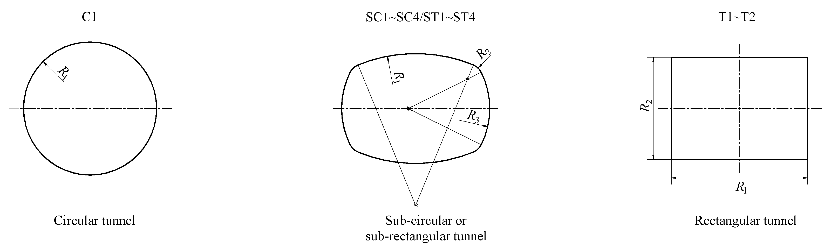
2. Collapse Mechanism for an Arbitrarily Shaped Tunnel Face

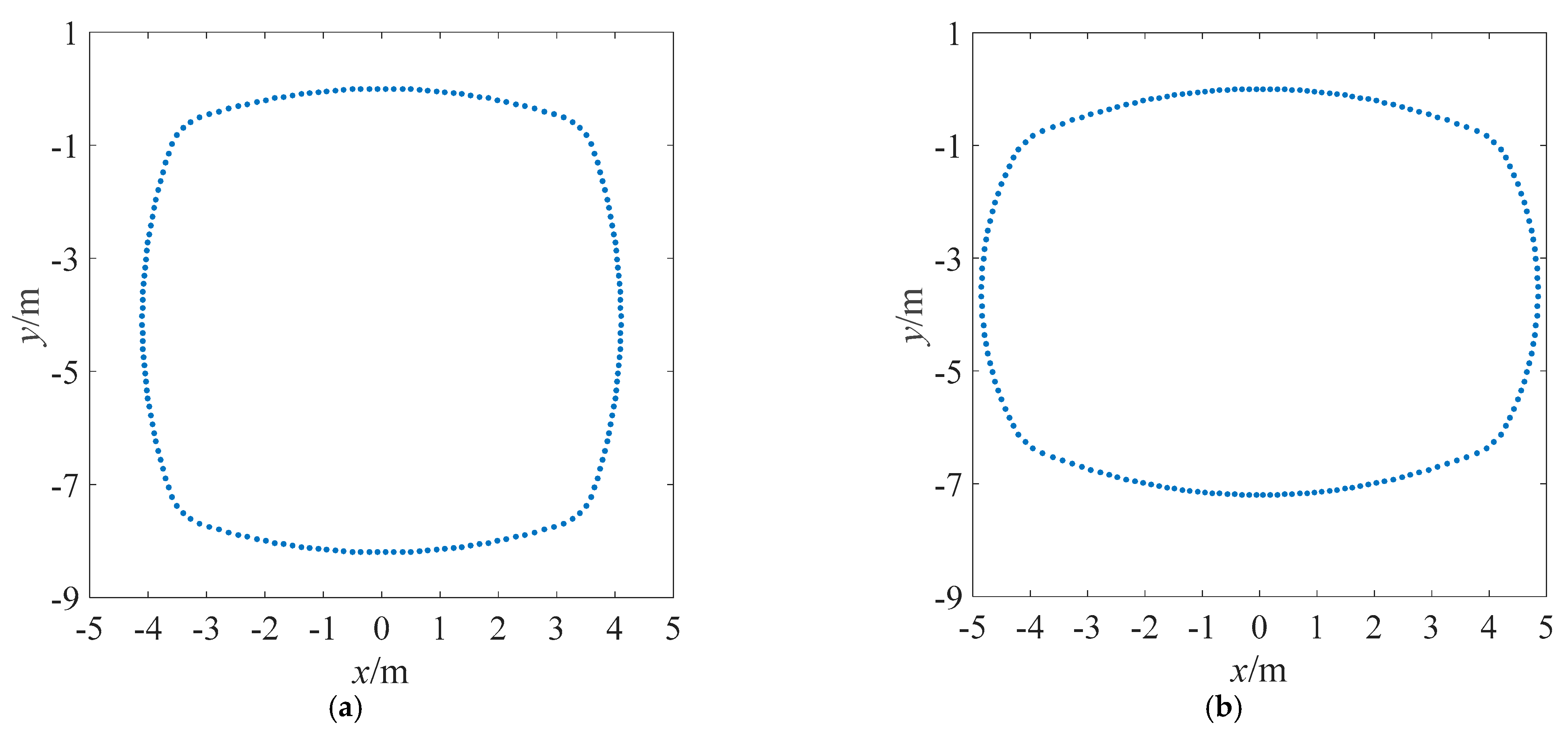
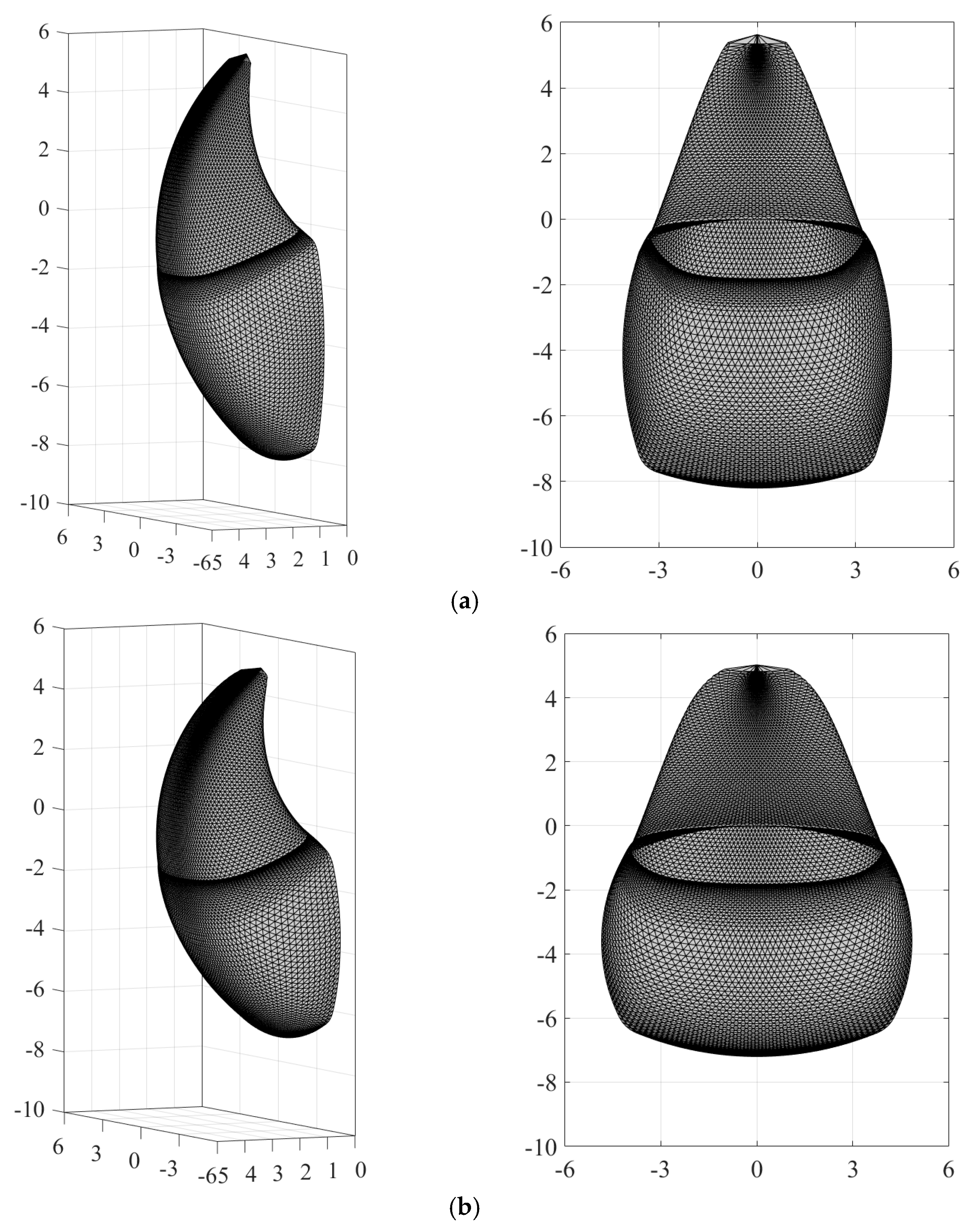
2.1. Generation of the 3D Failure Mechanism

The presented collapse mechanism for an arbitrarily shaped tunnel face is developed from the study of Mollon et al. [11]. As shown in Figure 1, an arbitrarily shaped tunnel face with a height of H and a width of L is considered. C is the burial depth of the tunnel. The upper and lower contours of the symmetry plane of the failure mechanism can be represented by two logarithmic spirals. They start from the tunnel roof A and the tunnel invert B, respectively, and intersect at point F. E is the center of tunnel face. L and H represent the maximum horizontal and vertical dimensions of the tunnel. The rotational failure mechanism requires that when the soil in front of the tunnel face fails, the block ABF is considered rigid and rotationally fails around the center O at an angular velocity ω. rE and βE, respectively, represent the length of OE and its angle from the vertical direction.
Then, the global coordinate system X-Y-Z is built with its origin at point A. The next step is to generate the failure mechanism with the spatial discretization technique developed by Mollon et al. [11]. In order to match different tunnel shapes, discrete points located on the tunnel contour should be reasonably determined. It is assumed that the tunnel face contour can be described by three different functions of y1, y2, y3. In practical tunnel design, four or more functions are probably used to outline the tunnel face. After analytically determining these functions, the discretized points on the contour of the tunnel face can be obtained according to a certain principle which should ensure the uniform distribution of those points. For a circular tunnel face, Mollon et al. [11] suggested that those points can be chosen based on the angles between the Y-axis and the lines connecting E and these points. However, when considering an irregular cross-sectional shape, the angle-based selection probably leads to non-uniformly distributed points on the tunnel face boundary, as shown in Figure 2, where θ0 is the angle, N is a positive integer, and L0 is the arc length. To solve this problem, the arc-length-based method is introduced to choose the discretized points in compliance with the principle of an equal arc length. This method is more complex than the one suggested by Mollon et al. [11] and it is based on the analytic formulas of these functions. It should be noted that the number of the discretized points on the tunnel face N should be even with respect to the symmetry of the cross-sectional shape.
Once the points on tunnel face are determined, the failure surface ahead of tunnel face can be obtained by finding the points on each radial plane with respect to the rotation center O. It can be seen from Figure 1 that the radial planes are perpendicular to the Y-Z plane and pass through the point O. These radial planes are divided into two sections: in Section I, each radial plane is determined by two symmetrical points on the tunnel face and the rotation center O; in Section II, each radial plane forms an angle δβ with the previous plane. We denote the inclination angle of each radial plane as βj. Therefore, the value of βj in Section I can be calculated according to the coordinates of known points on each plane, and it can be obtained by adding δβ to βj-1 in Section II. More details about the spatial discretization technique can be found in Mollon et al. [11].

2.2. The Work Rate Equation

According to the upper bound theorem of limit analysis, the work rate equation can be obtained by equating the internal energy dissipation rate to the external work rate. With the generated 3D collapse mechanism of the tunnel face, the total work rate involved in the tunnel face failure can be calculated by summing all the elementary work rates. To retain the tunnel face stability, a uniform support pressure σc is applied against face failure. So, the work rate carried out by face pressure Wσ can be obtained as follows:
W σ = S σ c v d S = ω σ c j S j 0 R j 0 cos β j 0
where Sj0 and Rj0, respectively, represent the area and rotation radius of j-th element on tunnel face, and βj0 denotes the angle at which the line connecting O and this element deviates from the vertical direction.
Likewise, the work rate of gravity can be calculated as follows:
W γ = V γ v d V = ω γ i j V i j R i j sin β i j
where Vij and Rij are the volume and rotation radius of the element ij, and βij denotes the angle at which the line connecting O and this element deviates from the vertical direction. γ is the unit weight of soil.
In order to assess the influence of seismic forces on the tunnel face’s stability, the pseudo-static method is adopted to include the seismic work rate into the energy equation. It is assumed that the whole failure mechanism is subjected to uniform horizontal and vertical seismic accelerations which are, respectively, contrary to the excavation direction and consistent with the gravity direction. The horizontal and vertical seismic coefficients, denoted as kh and kv, respectively, are introduced to idealize the seismic forces as horizontal and vertical inertial body forces khγ and kvγ. In this way, the most dangerous state of the tunnel face affected by earthquake can be considered. The horizontal seismic work rate can be formulated as follows:
W k h = V k h γ u z v d V = ω k h γ i j V i j R i j cos β i j
and the vertical one as follows:
W k v = V k v γ u y v d V = ω k v γ i j V i j R i j sin β i j
where u z = 0 , 0 , 1 , u y = 0 , 1 , 0 .
The internal energy dissipation can be computed as follows:
W D = S c v cos φ d S = ω c cos φ i j S i j R i j
where c, φ refer, respectively, to the cohesion and internal friction angle of the ground masses; Sij and Rij denote the elementary area of the failure surface and its rotation radius.
According to the upper-bound theorem of limit analysis, the work–energy equation is written as follows:
W σ + W γ + W k h + W k v = W D
Therefore, the critical face pressure σc is obtained as follows:
σ c = γ L N γ + k h γ L N k h + k v γ L N k v c N c
where Nγ, Nkh, Nkv, Nc are non-dimensional coefficients representing the contributions of gravity, horizontal inertial force, vertical inertial force and material resistance, respectively. Their expressions can be obtained from Equations (1)–(5), which can be written as follows:
N γ = i j V i j R i j sin β i j L j S j 0 R j 0 cos β j 0
N k h = i j V i j R i j cos β i j L j S j 0 R j 0 cos β j 0
N k v = i j V i j R i j sin β i j L j S j 0 R j 0 cos β j 0
N c = cos φ i j S i j R i j j S j 0 R j 0 cos β j 0

3. Application and Comparison

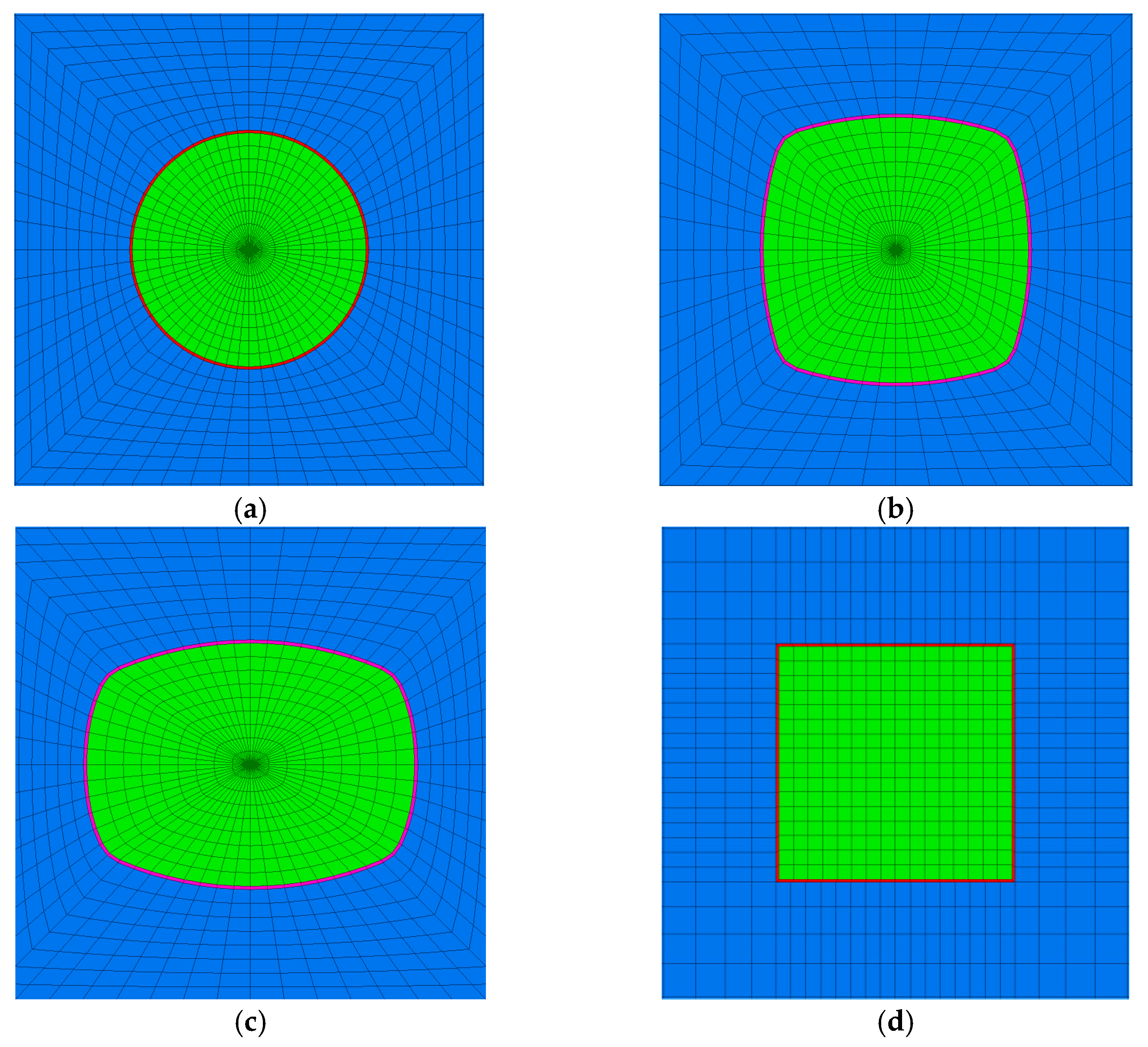
3.1. Parametric Analysis on the Tunnel Shape

Theoretical and numerical studies on the tunnel face stability usually assume a circular tunnel shape. Actually, multi-circular cross-sections are preferred instead of a simple circular or rectangular one in tunnel design practice. For a multi-circular tunnel, its geometric parameters may have a certain effect on the face stability. However, research on this is rather rare.
For this purpose, in Table 1, eleven sets of geometric parameters of different tunnel shapes are considered to study the shape effect on the tunnel face stability. In order to improve the credibility of the calculation results, those parameters are selected to comply with the principle of equal area. Moreover, the eleven cases are divided into two groups, depending on whether L is equal to H or not. The definition of the radii, namely R1, R2, R3, can be seen in Figure 3. The sub-circular and sub-rectangular tunnel shapes based on Table 1 are plotted in Figure 4.

3.2. Critical Face Pressures

In order to discuss the influence of tunnel face shapes, the critical face pressures for different cases given in Table 1 are computed using the proposed 3D failure mechanism of tunnel face. Two types of soils, involving a cohesive–frictional soil (c = 7 kPa, φ = 17°) and a frictional soil (c = 0 kPa, φ = 35°), are studied in this part. The unit weight of soil γ is set to 18 kN/m3 for both cases. Meanwhile, the seismic effect is considered by assuming kh = 0.1 and kv = 0.5kh. For the sake of investigating the influence of an earthquake on the tunnel face’s stability, the case of static analysis is provided for comparison.
As the circular or rectangular tunnel face is quite regular, the model construction can be readily obtained by referring to the work of Mollon et al. [11]. For a sub-circular or sub-rectangular tunnel face, the model construction should be started with point generation over the whole excavation face. According to Figure 3, the tunnel face is symmetric as regards its central axis marked by dotted lines; so, the boundary of the tunnel face in each quadrant can be defined by three different arcs. By referring to the parameters given in Table 1, analytical formulas of those arcs y can be easily expressed as functions of x in the X-Y plane, which is subordinate to the global coordinate system. Then, the failure surface can be generated based on the spatial discretization technique. To avoid redundancy, the SC3 and ST4 cases are selected as examples to illustrate the implementation of the proposed approach to generate the 3D failure surface of a non-circular tunnel. Figure 5 presents the discretized points on the tunnel face, and the generated failure mechanisms are shown in Figure 6.
Table 2 presents the critical face pressures considering the influence of the tunnel cross-sectional shape and seismic forces. It can be seen that the closer the tunnel shape is to a circle, greater the critical support pressure is. A sub-rectangular tunnel face is more beneficial to the tunnel face’s stability than a sub-circular one, although the difference is not very significant. The bigger difference in the critical face pressures induced by the shape effect is 15.3% for the cohesive–frictional soil case and 8.6% for the frictional soil case, for the C1 and ST4 cases. The seismic forces have a remarkable influence on the tunnel face’s stability. The critical face pressure increases by around 20% for both types of soil. The bigger increment is equal to 23.46% and comes from the ST4 case for the cohesive–frictional soil. In contrast, affected by seismic forces than the cohesive–frictional soil. It should be noticed that although the critical face pressure of a rectangular tunnel is the smallest according to Table 2, the rectangular one is not the first choice of a tunnel engineer due to the probably existing stress concentrations. So, the numerical simulation approach is employed to investigate the stress state of a rectangular tunnel face.

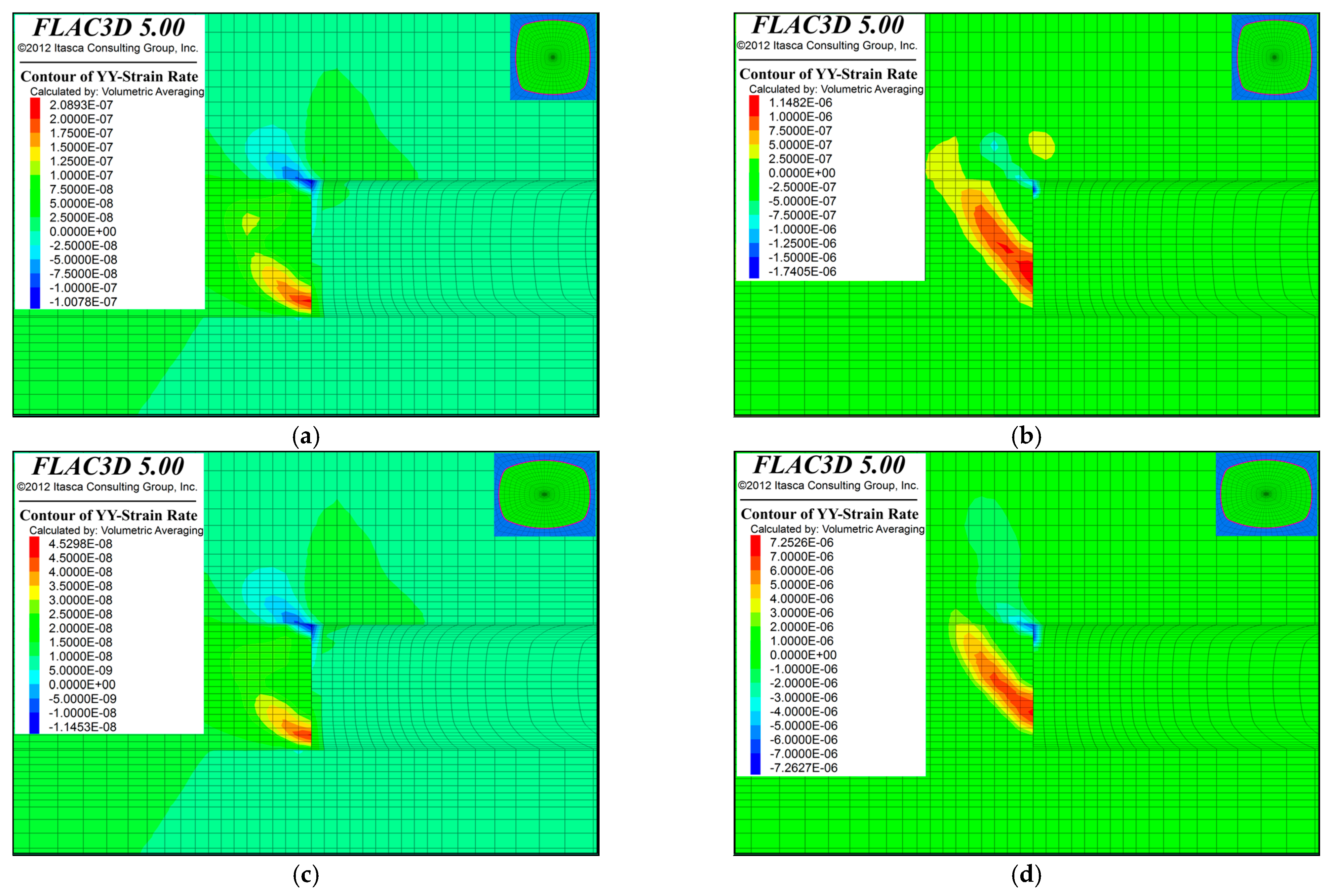
4. Validation with Numerical Simulations

This section focuses on the validation of the proposed approach using numerical simulation. The finite difference software FLAC3D is adopted to perform the tunnel face’s seismic stability analysis. In the numerical model, the pseudo-static approach is adopted with kh = 0.1 and kv = 0.5kh. The adopted numerical model consists of approximately 70,000 zones and a total of 75,000 nodes as shown in Figure 7. The Y-direction displacements of the nodes on the front and rear surfaces along the tunnel direction are fixed. Similarly, The X-direction displacements of the nodes on the front and rear surfaces perpendicular to the tunnel direction are fixed. The displacements of the nodes on the lower surface of the model in three directions are fixed. The bulk modulus and shear modulus of the soils are set to 50 MPa and 18 MPa, respectively. Those of the concrete liner are set to 21 GPa and 13 GPa, such as the elements in blue, to distinguish the deformation of different materials. A bisection method developed by Mollon et al. [28] is adopted here to determine the critical limit state of a tunnel face. Four cases of C1, SC3, ST4 and T1 are investigated for comparison purposes and the corresponding tunnel face shapes are shown in Figure 8.
Figure 9 gives the shear strain contour of the tunnel face at the critical limit state. It can be observed that the potential failure surface for the cohesive–frictional soil is gentler than that of the frictional soil. This phenomenon is in accordance with the limit analysis method. Table 3 presents the computed critical face pressures provided by numerical simulations and by the limit analysis method. It shows that the difference in the critical face pressure results (comparing the finite difference method and limit analysis method) are in the range from 20% to 30%. The shape effect on the critical face pressures is similar for the two methods according to Table 3, and the magnitude of the critical face pressures obtained is in the order of C1 > SC3 > ST4. However, contrary to the limit analysis method, the finite difference method indicates that the rectangular tunnel face requires a greater support pressure. It is probably due to the fact that the limit analysis model cannot fully consider the stress state around a rectangular tunnel in an accurate way due to the stress concentration at the corners. So, it can be concluded that among the cases provided in Table 1, ST4 is the most advisable tunnel cross-sectional pattern for underground excavations.

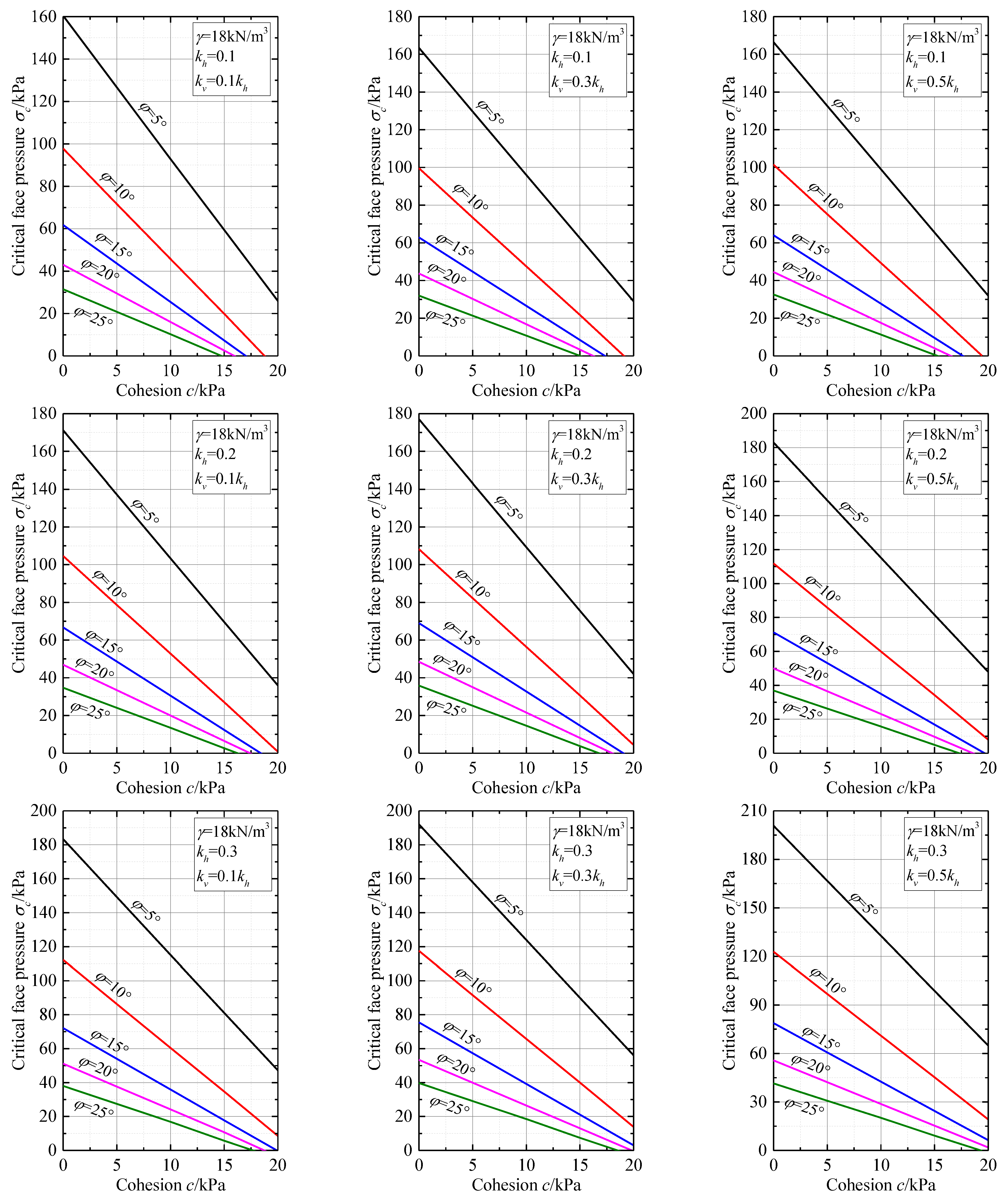
5. Seismic Stability Charts

As discussed above, the tunnel’s cross-sectional shape indeed affects the face’s stability, but seismic loading is another factor impacting tunnel face stability. As shown in Table 2, the seismic-force-induced increment in the critical face pressure is equal to 22% when kh = 0.1. As reported in previously published articles, the horizontal seismic coefficient is empirically set to range between 0.1 and 0.3 [29,30,31]. This would greatly impair the tunnel face’s stability. In order to facilitate the estimation of the necessary face pressures to resist to an earthquake, a series of stability charts are provided in this section based on the suggested tunnel shape of ST4, as shown in Figure 10. The critical face pressure σc is plotted as a function of cohesion c, where the unit weight of soil is set to 18 kN/m3, kh changes from 0.1 to 0.3 and kv from 0.1kh to 0.5kh. In each figure, c varies from 0 kPa to 20 kPa and φ from 5° to 25°.
It can be observed that the increase in c or φ leads to a decrease in the critical face pressure. A higher value of c will reduce the influence of the variation in φ on the tunnel face’s stability and vice versa. The horizontal seismic effect is more remarkable than the vertical one. This is mainly because the horizontal seismic coefficient is much bigger than the vertical one. Regarding this situation, some researchers only considered the seismic force along the horizontal direction in their studies on slope stability [31]. However, in the case of an underground excavation, the failure zone can extend along the vertical direction when the value of friction angle is small. Furthermore, in a large earthquake, the vertical seismic effect on the tunnel face’s stability is not negligible.

6. Conclusions

This work aims to propose an accurate and efficient method to estimate the critical face pressure of a tunnel driven by shield machine. The proposed method has the advantage of considering a variety of tunnel shapes and is highly efficient compared to numerical simulations. The pseudo-static method is used to model the seismic force impact as an inertial body force that contributes to the tunnel face’s failure. The following conclusions can be drawn:
The tunnel shape’s influence on the tunnel face’s stability is significant. For example, the difference in the critical face pressures due to tunnel shape can be up to 15.25% for a cohesive–frictional soil case and 8.56% for a frictional soil case. It must be noted that the critical face pressure of rectangular tunnels is the lowest based on the estimation of the limit analysis model. The seismic effect on the tunnel face’s stability is important. The increment in critical face pressure induced by seismic forces can reach 20% when the horizontal seismic coefficient is equal to 0.1. The bigger increment is 23.46% when considering the ST4 tunnel shape with a cohesive–frictional soil.
A comparison with numerical simulations shows that the differences between the two methods are in the range from 20% to 30%. The same tendency was found between the two adopted methods, and the order of the critical face pressures is C1 > SC3 > ST4.
The proposed approach is an effective method to deal with the face stability problem of tunnels with different cross-sectional shapes, which has significant advantages in tunnel excavation designs considering a wide range of soil parameters. Owing to its fast computational speed, several seismic stability charts are provided for parametric analysis, which show that the horizontal seismic effect is the more significant than the vertical one.

Author Contributions

Conceptualization, T.L.; Methodology, Y.J.; Software, T.L.; Formal analysis, C.P. and F.L.; Investigation, Y.J.; Resources, F.L.; Data curation, C.P.; Writing—original draft, T.L.; Writing—review & editing, C.P. and T.L. All authors have read and agreed to the published version of the manuscript.

Funding

This study was financially supported by the National Natural Science Foundation of China (No. 42102321). The financial support is greatly appreciated.

Data Availability Statement

The data used to support the findings of this study are available from the corresponding author upon request.

Conflicts of Interest

Authors Yunfu Jia and Yuancheng Pei were employed by the company Xinjiang Water Conservancy and Hydropower, Survey and Design Institute Co., Ltd. Author Feng Liang was employed by the company Xinjiang Shuifa Construction Group Co., Ltd. The remaining author declares that the research was conducted in the absence of any commercial or financial relationships that could be construed as a potential conflict of interest.

References

  1. Zakhem, A.M.; El Naggar, H. Effect of the constitutive material model employed on predictions of the behaviour of earth pressure balance (EPB) shield-driven tunnels. Transp. Geotech. 2019, 21, 100264. [Google Scholar] [CrossRef]
  2. Banerjee, S.K.; Chakraborty, D. Stability analysis of a circular tunnel underneath a fully liquefied soil layer. Tunn. Undergr. Space Technol. 2018, 78, 84–94. [Google Scholar] [CrossRef]
  3. Li, T.; Gong, W.; Tang, H.; Zhang, L. A meshed kinematical approach for 3D slope stability analysis. Int. J. Numer. Anal. Methods Geomech. 2022, 46, 2913–2930. [Google Scholar] [CrossRef]
  4. Moeinossadat, S.R.; Ahangari, K. Estimating maximum surface settlement due to EPBM tunneling by Numerical-Intelligent approach–A case study: Tehran subway line 7. Transp. Geotech. 2019, 18, 92–102. [Google Scholar] [CrossRef]
  5. Roateşi, S. Analytical and numerical approach for tunnel face advance in a viscoplastic rock mass. Int. J. Rock Mech. Min. Sci. 2014, 70, 123–132. [Google Scholar] [CrossRef]
  6. Soomro, M.A.; Ng, C.W.W.; Memon, N.A.; Bhanbhro, R. Lateral behaviour of a pile group due to side-by-side twin tunnelling in dry sand: 3D centrifuge tests and numerical modelling. Comput. Geotech. 2018, 101, 48–64. [Google Scholar] [CrossRef]
  7. Zuo, Y.; Xu, T.; Zhang, Y.; Zhang, Y.; Li, S.; Zhao, G.; Chen, C. Numerical study of zonal disintegration within a rock mass around a deep excavated tunnel. Int. J. Geomech. 2011, 12, 471–483. [Google Scholar] [CrossRef]
  8. Leca, E.; Dormieux, L. Upper and lower bound solutions for the face stability of shallow circular tunnels in frictional material. Geotechnique 1990, 40, 581–606. [Google Scholar] [CrossRef]
  9. Mollon, G.; Dias, D.; Soubra, A.H. Face stability analysis of circular tunnels driven by a pressurized shield. J. Geotech. Geoenviron. Eng. 2009, 136, 215–229. [Google Scholar] [CrossRef]
  10. Subrin, D.; Wong, H. Tunnel face stability in frictional material: A new 3D failure mechanism. Comptes Rendus Mec. 2002, 330, 513–519. [Google Scholar] [CrossRef]
  11. Mollon, G.; Dias, D.; Soubra, A.H. Rotational failure mechanisms for the face stability analysis of tunnels driven by a pressurized shield. Int. J. Numer. Anal. Methods Geomech. 2011, 35, 1363–1388. [Google Scholar] [CrossRef]
  12. Perazzelli, P.; Leone, T.; Anagnostou, G. Tunnel face stability under seepage flow conditions. Tunn. Undergr. Space Technol. 2014, 43, 459–469. [Google Scholar] [CrossRef]
  13. Pan, Q.; Dias, D. Three dimensional face stability of a tunnel in weak rock masses subjected to seepage forces. Tunn. Undergr. Space Technol. 2018, 71, 555–566. [Google Scholar] [CrossRef]
  14. Kargar, A.R.; Rahmannejad, R.; Hajabasi, M.A. A semi-analytical elastic solution for stress field of lined non-circular tunnels at great depth using complex variable method. Int. J. Solids Struct. 2014, 51, 1475–1482. [Google Scholar] [CrossRef]
  15. Lu, A.; Zhang, N.; Kuang, L. Analytic solutions of stress and displacement for a non-circular tunnel at great depth including support delay. Int. J. Rock Mech. Min. Sci. 2014, 70, 69–81. [Google Scholar] [CrossRef]
  16. Pan, Q.; Dias, D. Safety factor assessment of a tunnel face reinforced by horizontal dowels. Eng. Struct. 2017, 142, 56–66. [Google Scholar] [CrossRef]
  17. Ye, Z.K.; Ai, Z.Y. A matrix-form complex variable method for multiple non-circular tunnels in layered media. Appl. Math. Model. 2024, 131, 570–595. [Google Scholar] [CrossRef]
  18. Hou, C.; Yang, X.; Liu, M.; Chen, M.; Wu, Z.; Long, G. Stability assessment of a non-circular tunnel face with tensile strength cut-off subject to seepage flows: A comparison analysis. Comput. Geotech. 2023, 163, 105764. [Google Scholar] [CrossRef]
  19. Wu, Z.; Cui, Y.; Barrett, A.G.; Moreno, M.M.; Deng, Y. Role of surrounding soils and pore water in calcium carbonate precipitation in railway tunnel drainage system. Transp. Geotech. 2019, 21, 100257. [Google Scholar] [CrossRef]
  20. Lee, I.M.; Nam, S.W.; Ahn, J.H. Effect of seepage forces on tunnel face stability. Can. Geotech. J. 2003, 40, 342–350. [Google Scholar] [CrossRef]
  21. Shin, Y.J.; Song, K.I.; Lee, I.M.; Cho, G.-C. Interaction between tunnel supports and ground convergence—Consideration of seepage forces. Int. J. Rock Mech. Min. Sci. 2011, 48, 394–405. [Google Scholar] [CrossRef]
  22. Wijaya, H.; Rajeev, P.; Gad, E. Effect of seismic and soil parameter uncertainties on seismic damage of buried segmented pipeline. Transp. Geotech. 2019, 21, 100274. [Google Scholar] [CrossRef]
  23. Sahoo, J.P.; Kumar, J. Seismic stability of a long unsupported circular tunnel. Comput. Geotech. 2012, 44, 109–115. [Google Scholar] [CrossRef]
  24. Ganesh, R.; Prasad Sahoo, J. Seismic Passive Resistance of Cohesive-Frictional Soil Medium: Kinematic Limit Analysis. Int. J. Geomech. 2017, 17, 04017029. [Google Scholar] [CrossRef]
  25. Saada, Z.; Maghous, S.; Garnier, D. Pseudo-static analysis of tunnel face stability using the generalized Hoek–Brown strength criterion. Int. J. Numer. Anal. Methods Geomech. 2013, 37, 3194–3212. [Google Scholar] [CrossRef]
  26. Davoodi, M.; Senent, S.; Keshavarz, A.; Jimenez, R. Three-dimensional seismic face stability of shield tunnels in undrained clay. Undergr. Space 2024, 15, 26–43. [Google Scholar] [CrossRef]
  27. Vo-Minh, T.; Nguyen-Son, L.; Nguyen, T.A. Stable node-based smoothed finite element method for seismic stability analysis of a square tunnel in cohesive-frictional soils. Tunn. Undergr. Space Technol. 2023, 141, 105346. [Google Scholar] [CrossRef]
  28. Mollon, G.; Dias, D.; Soubra, A.H. Continuous velocity fields for collapse and blowout of a pressurized tunnel face in purely cohesive soil. Int. J. Numer. Anal. Methods Geomech. 2013, 37, 2061–2083. [Google Scholar] [CrossRef]
  29. Xu, J.; Yang, X. Seismic stability analysis and charts of a 3D rock slope in Hoek–Brown media. Int. J. Rock Mech. Min. Sci. 2018, 112, 64–76. [Google Scholar] [CrossRef]
  30. Li, T.; Gong, W.; Tang, H. Three-dimensional stochastic geological modeling for probabilistic stability analysis of a circular tunnel face. Tunn. Undergr. Space Technol. 2021, 118, 104190. [Google Scholar] [CrossRef]
  31. Li, A.J.; Lyamin, A.V.; Merifield, R.S. Seismic rock slope stability charts based on limit analysis methods. Comput. Geotech. 2009, 36, 135–148. [Google Scholar] [CrossRef]
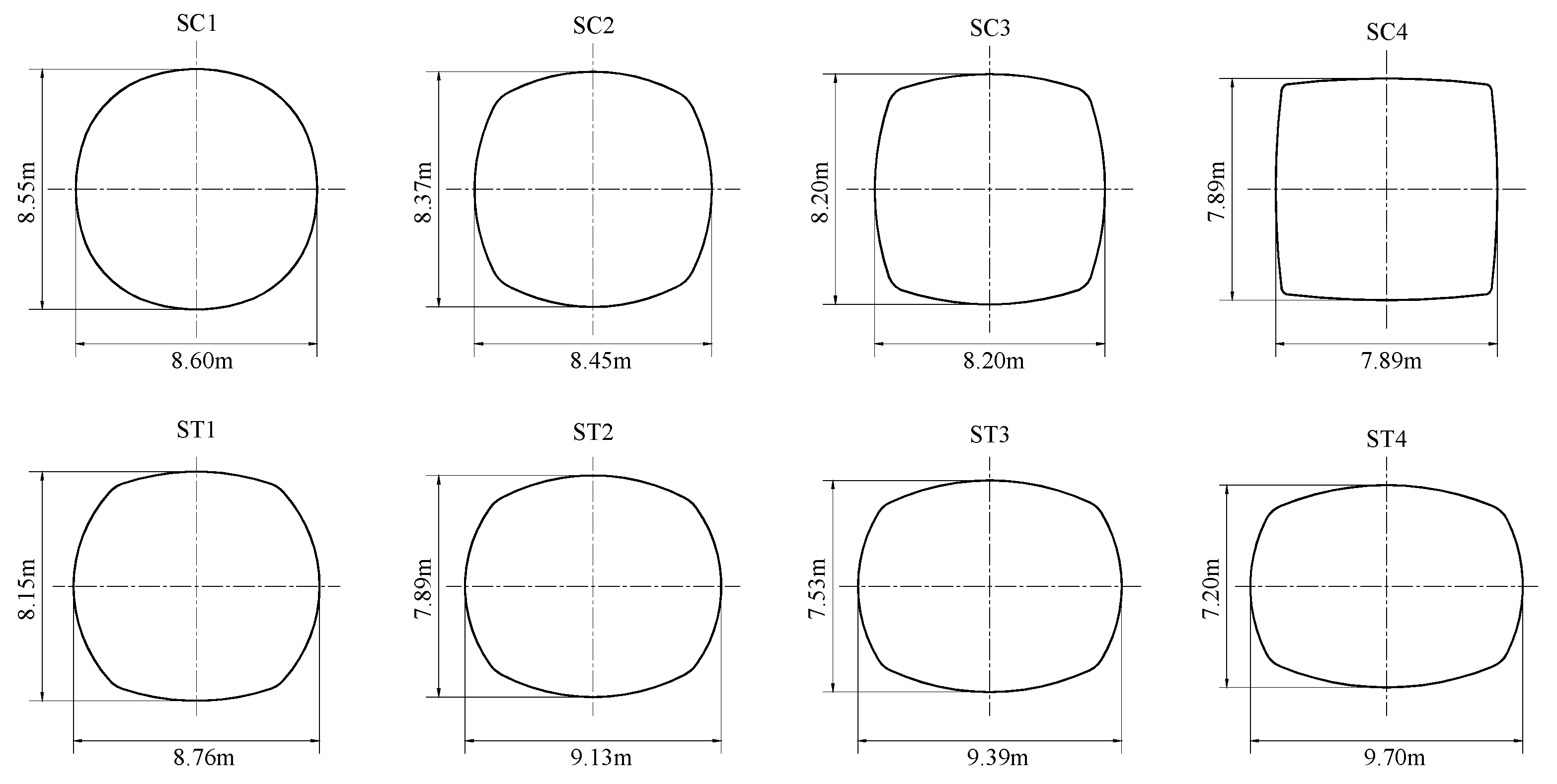
Figure 1. The discretization-based collapse mechanism of an arbitrarily shaped tunnel face.
Buildings 14 01760 g001
Figure 2. The selection of points on the contour of tunnel face.
Buildings 14 01760 g002
Figure 3. Definition of the radii of tunnels with different cross-sectional shapes.
Buildings 14 01760 g003
Figure 4. Cross-sections for sub-circular and sub-rectangular tunnels.
Buildings 14 01760 g004
Figure 5. Discretized points on the tunnel face contour (a) SC3 case (b) ST4 case.
Buildings 14 01760 g005
Figure 6. Failure surface for the cohesive–frictional soil case: (a) SC3 case, (b) ST4 case.
Buildings 14 01760 g006
Figure 7. Numerical model used.
Buildings 14 01760 g007
Figure 8. The tunnel face model of FLAC3D: (a) case C1, (b) case SC3, (c) case ST4, (d) case T1.
Buildings 14 01760 g008
Figure 9. Contour of the shear strain rate at the ultimate limit state: (a) cohesive–frictional soil—case SC3, (b) frictional soil—case SC3, (c) cohesive–frictional soil—case ST4, (d) frictional soil—case ST4.
Buildings 14 01760 g009
Figure 10. Seismic stability charts for the sub-rectangular tunnel face of ST4.
Buildings 14 01760 g010
Table 1. Geometric parameters of different tunnel cross-sectional shapes.
CaseR1/mR2/mR3/mL/mL/HArea/m2Type of Tunnel Shape
LHC14.36--8.721.0059.786Circular (Reference case)
SC15.473.675.478.601.0159.759Sub-circular
SC26.561.236.568.451.0159.795
SC39.880.859.888.201.0059.812
SC425.830.2525.837.891.0059.778
T17.737.73-7.731.0059.753Rectangular (Reference case)
L > HST18.361.024.998.761.0759.788Sub-rectangular
ST27.091.234.819.131.1659.757
ST38.500.965.079.391.2559.778
ST49.951.005.359.701.3559.786
T210.005.98-10.001.6759.786Rectangular (Reference case)
Table 2. Critical face pressures (kPa) for different tunnel shapes.
CaseCohesive–Frictional SoilFrictional Soil
kh = 0kh = 0.1Increment/%kh = 0kh = 0.1Increment/%
C130.3835.8918.14%17.2220.0216.24%
SC130.1036.6821.89%17.1520.1717.57%
SC229.3635.8522.10%16.8419.7717.38%
SC328.3134.6922.54%16.4019.1816.89%
SC426.4732.3822.32%15.8718.3115.63%
T125.6231.6523.53%14.6517.7721.31%
C130.3835.8918.14%17.2220.0216.24%
ST129.2635.7522.17%16.8419.8017.58%
ST228.6435.0722.44%16.6319.5617.63%
ST327.5433.8622.95%16.2619.1417.73%
ST426.3632.5523.46%15.8618.7017.87%
T221.4826.9925.66%13.5416.0518.58%
Table 3. Comparison of the critical face pressures (kPa) between the limit analysis and numerical method.
CaseCohesive–Frictional SoilFrictional Soil
Limit AnalysisFLAC3DDifference/%Limit AnalysisFLAC3DDifference/%
C135.8948.82−26.49%20.0216.0924.44%
SC334.6943.75−20.71%19.1815.0827.16%
ST432.5542.46−23.34%18.7014.3830.03%
T131.6557.27−44.73%17.7727.47−35.32%
Disclaimer/Publisher’s Note: The statements, opinions and data contained in all publications are solely those of the individual author(s) and contributor(s) and not of MDPI and/or the editor(s). MDPI and/or the editor(s) disclaim responsibility for any injury to people or property resulting from any ideas, methods, instructions or products referred to in the content.

