Article

Evaluation of a Simplified Direct SSI Method in the Dynamic Seismic Behavior of Traditional RC Minarets

by
Erdem Türkeli
Construction Department, Vocational School of Technical Sciences, Ordu University, Ordu 52200, Turkey
Buildings 2024, 14(6), 1796; https://doi.org/10.3390/buildings14061796
Submission received: 30 March 2024 / Revised: 30 May 2024 / Accepted: 3 June 2024 / Published: 13 June 2024
(This article belongs to the Section Building Materials, and Repair & Renovation)

Abstract

:
Several reinforced concrete minarets in Turkey have suffered significant damage during earthquakes, resulting in fatalities and economic losses. These structures might be considered the most frequently built thin structures in Turkey. To improve seismic resistivity, it is necessary to figure out the exact nature of these tall structures. In this way, the existing ones can be strengthened. This study examined the most widely built (traditional) forms of reinforced concrete minarets under two earthquakes, the Mw 7.2 Van on 23 October 2011 and the Mw 7.4 İzmit on 17 August 1999, by considering three types of soils, i.e., stiff, medium and soft, with the viscous boundary method proposed from Burman et al. Moreover, diameter of the soil was selected as ten times the diameter of the foundation of the minarets. After conducting numerous analyses, it was concluded that the RC minarets’ structural behavior was altered by the softening of the earth, leading to a sharp increase in internal forces. Furthermore, it was discovered that the regions of stress accumulation indicated for the representative minarets matched the damage shown in recent earthquakes.

1. Introduction

The most often built tall, thin structures in Turkey are reinforced concrete (RC) minarets, which have Islamic architectural influences. The essential components of an RC minaret are shown in Figure 1 [1].
There are two or three mosques with RC minarets of varying heights and geometric configurations in practically every district in Turkey. When prayer times arrived in the past, minarets were used to alert those who were far from the mosques. But, as time goes on and technology advances, it becomes less important to announce the azan from the minarets. However, they also served to complete the mosques’ architectural grandeur and impressiveness. As a result, minarets are more often built tall and narrow, which increases their susceptibility to wind and seismic activity.
According to Erdik et al. [2], Turkey is located in a seismically active area of the world with an extensive and well-documented history of earthquakes. Numerous devastating and catastrophic earthquake events have resulted in losses of life and economic damage. A few of them are [3,4,5,6,7] 13 March 1992 Mw 6.8 Erzincan, 17 August 1999 Mw 7.4 İzmit, 12 November 1999 Mw 7.1 Düzce, 23 October 2011 Mw 7.2 Van, 06 February 2023 Mw 7.7 and Mw 7.6 Kahramanmaraş. Furthermore, a great number of RC minarets are said to have suffered significant damage or have collapsed as a result of these extreme events of nature [8,9,10,11,12,13,14,15,16,17]. Another important fact about the majority of RC minarets that are built is that they are typically built by skilled laborers or contractors without the use of engineering expertise or application projects [18]. Consequently, these tall, thin structures are more susceptible to seismic damage.
A crucial topic that needs to be taken into account when conducting the dynamic analysis of the structures is soil–structure interaction (SSI) [19,20,21,22]. When assessing how RC minarets respond dynamically to earthquakes, the SSI impact is also quite significant. Some research studies addressing the SSI of RC minarets can be found in the technical literature [11,23,24]. Other than these, the SSI effect is typically ignored when investigating RC minarets’ dynamic earthquake response [10,25,26,27,28,29,30,31,32,33,34,35].
Also, Acar et al. [11] investigated the earthquake behavior of reinforced concrete representative minarets which are located on the four different subsoil classes defined in the Turkish Earthquake Code (2007). Hacıefendioğlu et al. [36] dealt with the dynamic modal analysis of a scaled RC minaret embedded in different soil types. Altun [37] studied the structural analysis of a traditional model of reinforced concrete minarets for different soil classes considering the 2007 and 2018 Turkey earthquake regulations. Türkeli [38] analyzed the seismic behavior of strengthened (with FRP and buttresses) and the most common constructed types of RC minarets by considering soil–structure interaction.
In this study, the dynamic response of the most commonly constructed types of representative RC minarets were investigated by taking into account the impact of the SSI. In this manner, the dynamic analyses of the cited representative minarets were performed by selecting the diameter of the soil as 10R. R is the diameter of the foundation of the considered minaret. Also, three types of soils, namely soft, medium and stiff type of soils, were considered for the structural analysis. Additionally, the structural analysis program SAP2000 was utilized to generate three-dimensional (3D) models of the minarets [39]. In the superstructure of the representative minarets, shell elements were used. Also, solid elements were utilized when creating the foundation and the soil. Three types of soils [40], namely soft (S3), medium (S2) and stiff soil (S1), were taken account in the dynamic analyses. As is well known, one of the most significant and prevalent topics in the SSI problems that requires careful attention is the numerical method’s modeling of infinite media. As a result, the general approach for resolving this problem is to split the infinite medium into two parts: the far field, which can be simplified to be an isotropic homogeneous elastic medium, and the near field (truncated layer), which includes the irregularity and non-homogeneity of the soil next to the structure. Finite elements are used to simulate the near field, while additional specific artificial boundaries between elements are used to treat the distant field. Using transmitted boundaries is one of the most suitable approximations [40]. These boundaries can also be utilized to stop the radiation and reflecting effects of waves that are propagating from the structure–foundation layer. Using the one-dimensional beam theory, Lysmer and Kuhlemeyer [41] created a viscous barrier in 1969, and FEM has frequently employed this theory since then [42,43]. In this study, a simplified direct method for the soil media that is represented by Burman et al. [44] was used for the dynamic seismic analyses of representative minarets. Furthermore, the representative minarets were subjected to two devastating seismic time history records, the 1999 Mw 7.4 İzmit earthquake and the 2011 Mw 7.2 Van earthquake. Following the investigation, a few broad conclusions and recommendations were made.

2. Materials and Methods

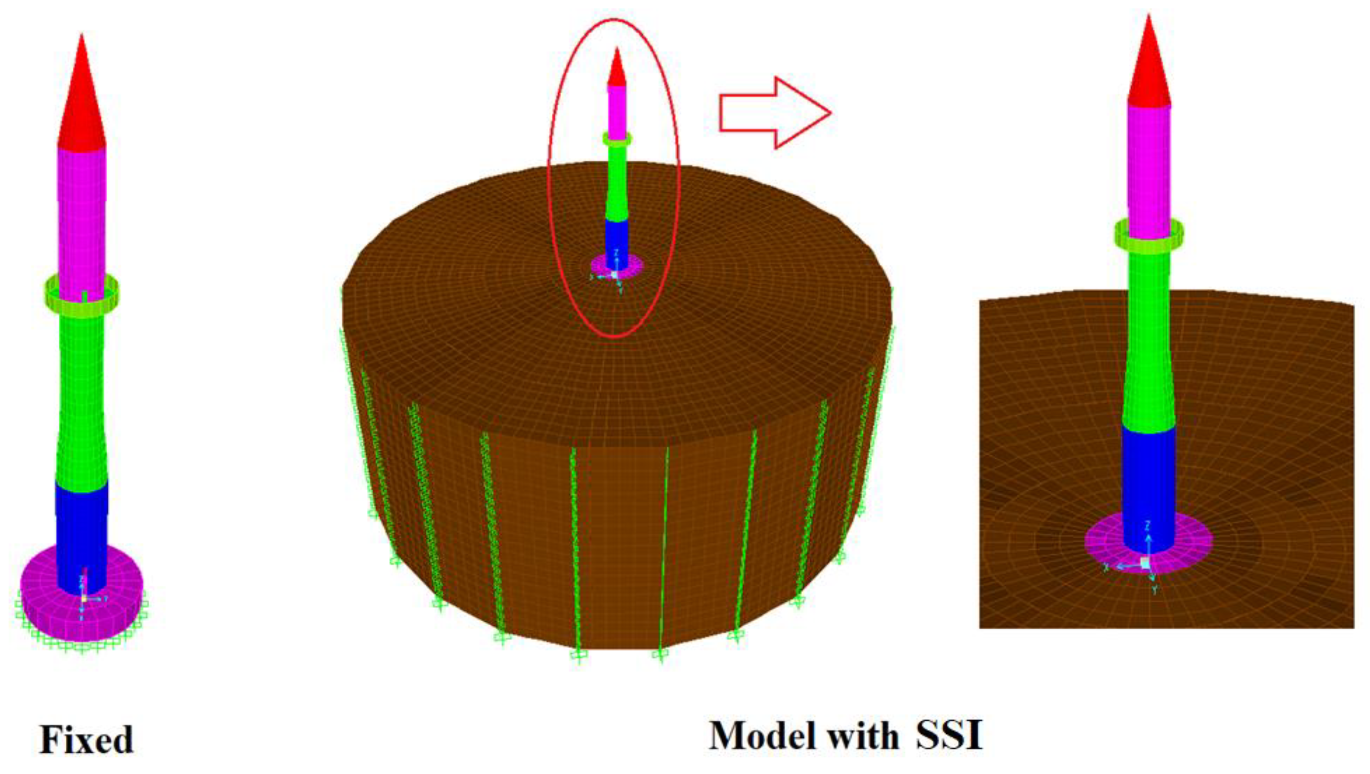
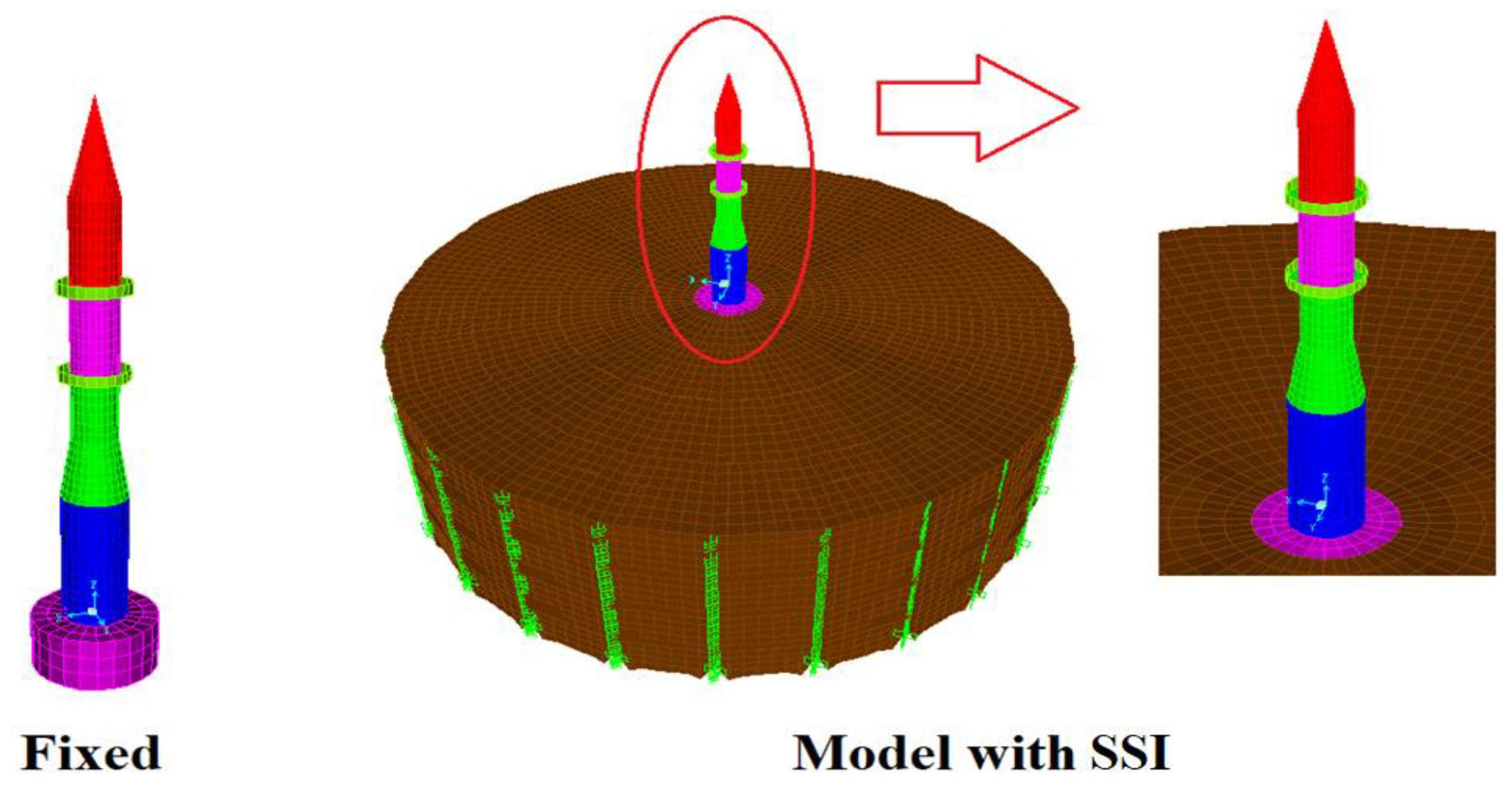
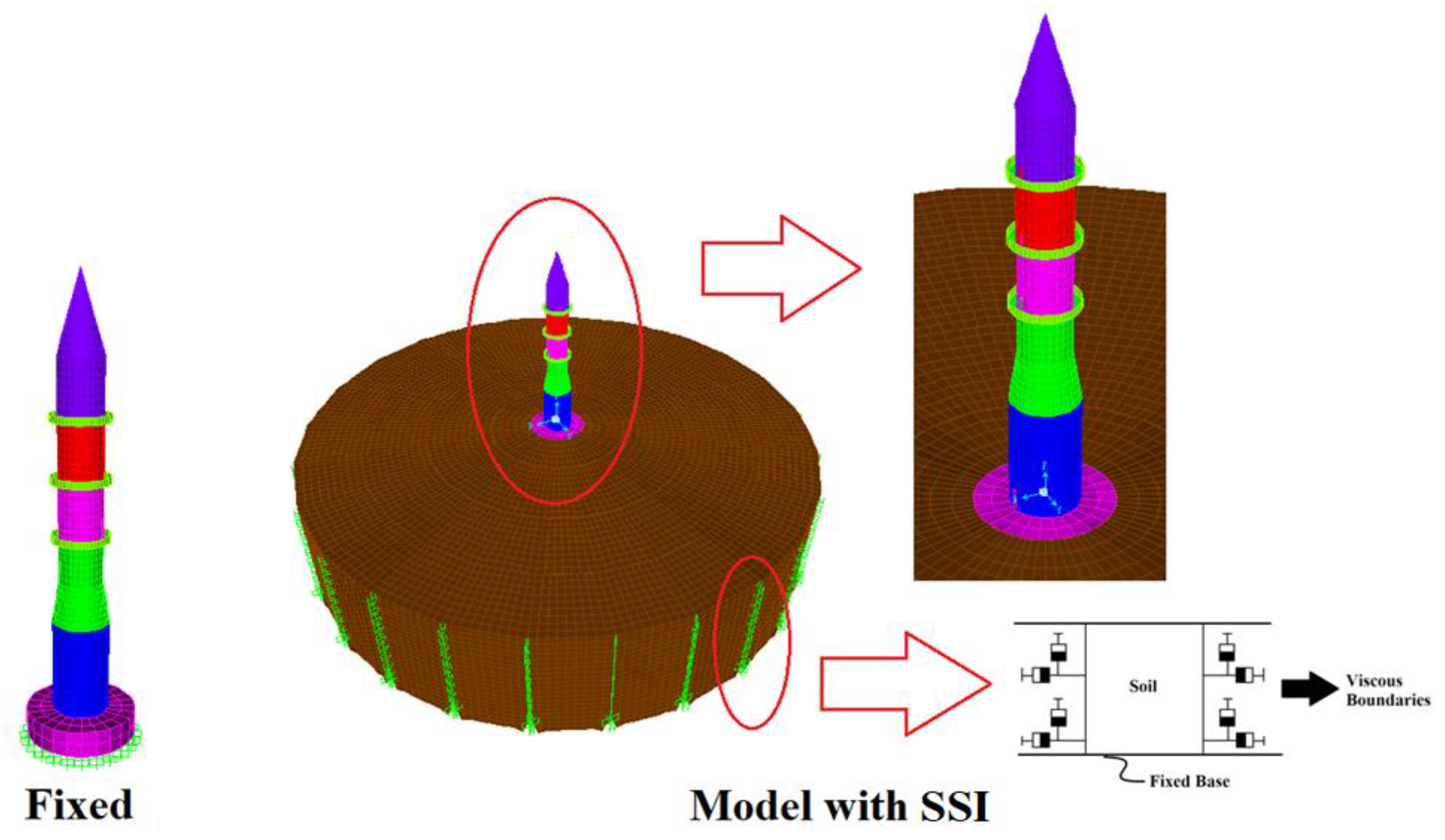
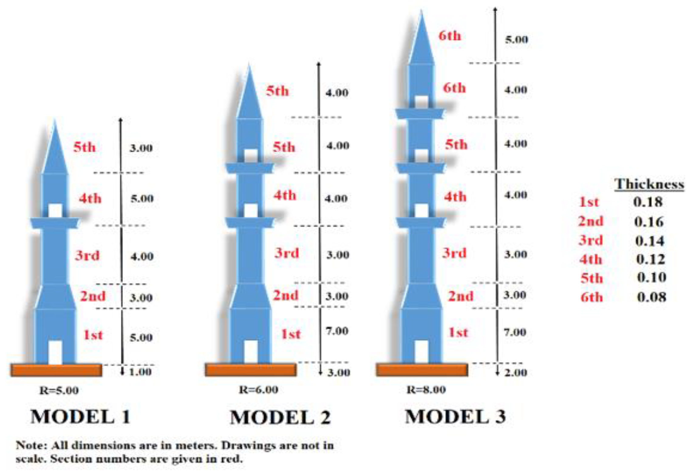
2.1. Finite Element Models of the Minarets

The finite element models of three representative minarets were produced by using the SAP2000 structural analysis program. The finite element models of these three representative minarets are given in Figure 2, Figure 3 and Figure 4. Models 1, 2 and 3 have one, two and three balconies, respectively. Additionally, Models 1, 2 and 3 each have two, three and four door holes. The first of these holes serves as an entrance, while the remaining openings are situated at the balcony level. The door holes on all models have rectangular shapes and are 1.50 m in height. Furthermore, at the designated heights, the breadth of door openings forms an arc length that circumscribes a 30° angle. All of the models have foundations embedded in the underlying soil. The foundation sizes for Models 1, 2 and 3 are, in radius–depth, 5.00–1.00 m, 6.00–3.00 m and 8.00–2.00 m, respectively. It is assumed for all typical models that the soil is 20 m thick and that once the soil reaches this height, it is anchored to the main rock and can be considered firm. Additionally, it is considered that the soil underneath the structures is homogeneous. The foundations and superstructures of the representative models were constructed using RC. The assumptions made for the material’s parameters included unit weight, Young’s modulus, Poisson’s ratio, and concrete compressive strength (which is typically utilized in practice) of 23.5 kN/m3, 30,000 MPa, 0.2 and 16 MPa, respectively. Compressive strength is a typical value among these properties that is most frequently seen in everyday circumstances.
Figure 5 displays the fundamental geometrical characteristics of the minarets.
The interaction between the mosque’s main wall and minaret are not taken into account in the typical models of representative minarets. Furthermore, wind effects are outside the boundaries of the current study.

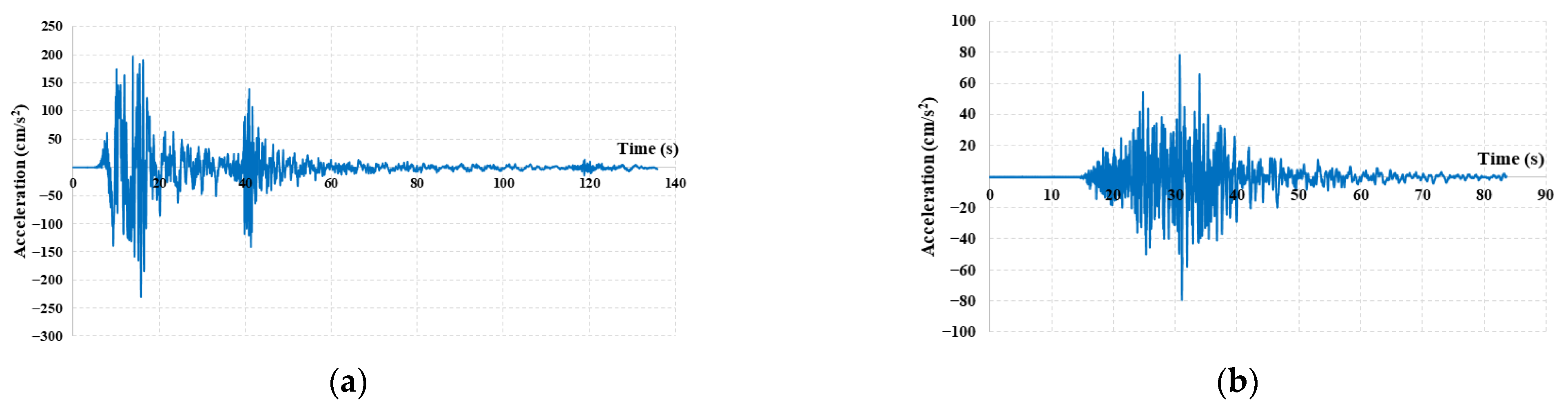
2.2. Selected Ground Motions

Two recorded ground motions from the 17 August 1999 Mw 7.4 İzmit earthquake and the 23 October 2011 Mw 7.2 Van earthquake were applied to the minaret models [45] in the dynamic modal time history analysis. The time histories of the mentioned ground motions are shown in Figure 6.
Both the dynamic analysis that was carried out and the findings presented in the present study fell within a linear range. The İzmit earthquake of 17 August 1999 was applied in 27,163 stages at intervals of 0.005 s. Additionally, the Van earthquake of 23 October 2011 was applied using 10,714 steps and 0.0078 s time intervals. Even if these time history stages are fully applied to every model, the graphs become unreadable for full durations and are not appropriate for comparison, so it is not possible to display all durations for the analysis’s results.
As a result, the following sections provide the effective duration intervals that produce the maximum responses. Based on the author’s parametric study results, the input ground motion was applied to all models solely in the x-direction, i.e., in just one horizontal direction. Based on the findings of this parametric analysis, it was determined that the crucial axis that generated the greatest response for the application of dynamic loads passed over the axis that split the door holes into two equal arcs. The analysis durations for the ground motions given in Figure 6 change from 2 min to 10 min according to the finite element number of the model considered. For example, for Model 1 (no SSI effect), the duration of the analyses is only 2 min. However, for Model 1 with SSI, the duration of the analyses is approximately 10 min. Therefore, it is very time consuming and intensive to perform the seismic analyses of the models under two earthquake motions with three types of soils.

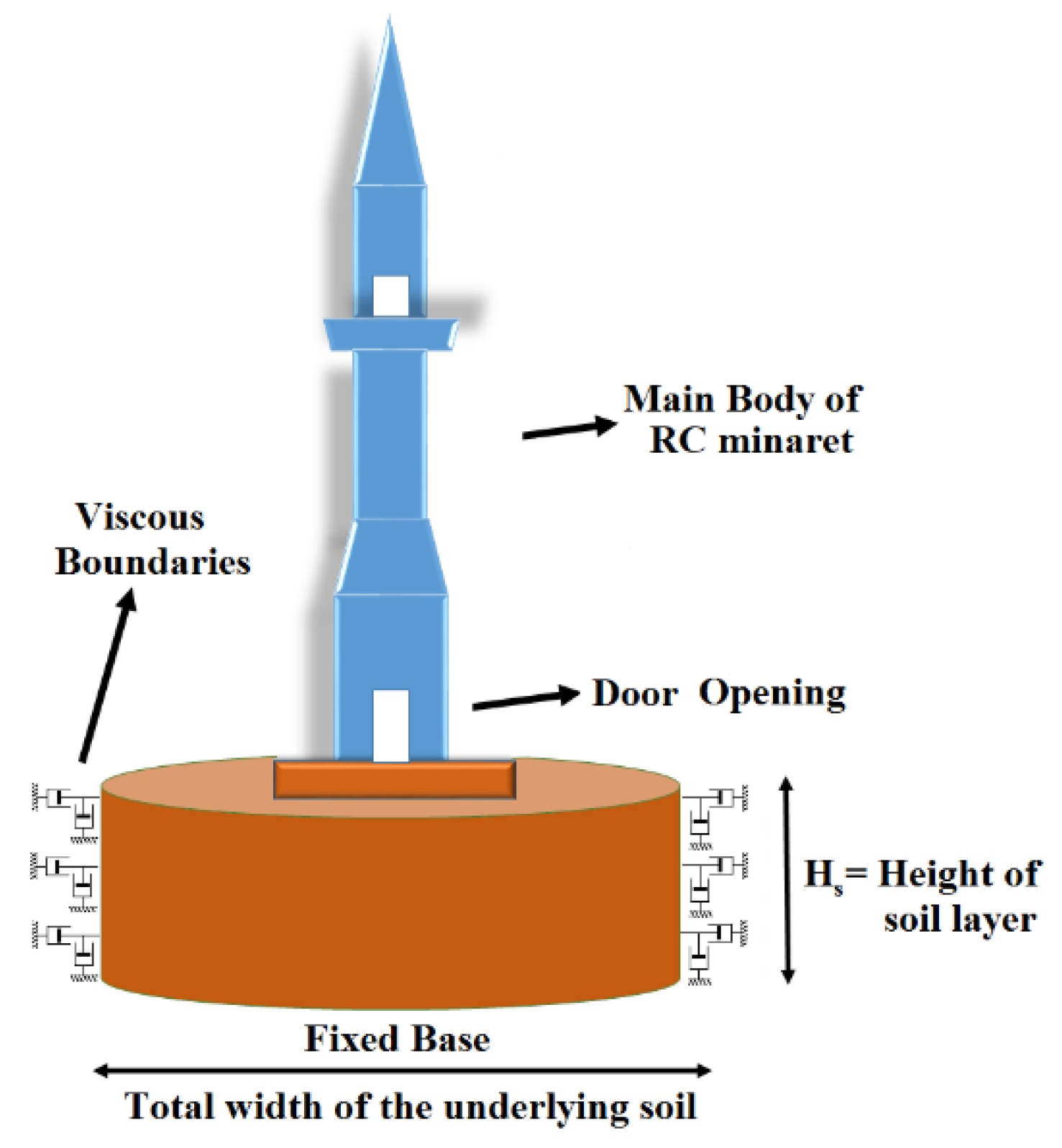
2.3. Modeling and the Properties of Underlying Soil

In this study, three types of soils, namely S1 (stiff), S2 (medium) and S3 (soft), are chosen from the research paper [40] and applied to the representative minaret models. Table 1 lists the characteristics of the soil types taken into consideration.
The problem of regenerating the infinite underlying soil beneath the RC minarets can be solved by modeling the near-field soil with solid finite components and accounting for the remaining infinite soil by adding artificial bounds to the end of the near field, as shown in Figure 7. These kinds of boundaries can be used to prevent the propagating waves from the structural foundation layer from reflecting and radiating [40].
In the present study, the Burman et al. [44] approach was applied to the viscous boundaries illustrated in Figure 4 and Figure 7.
According to Burman et al.’s method [44], the following is conducted:
Equations (1) and (2) can be used to find the tangential and normal damping coefficients.
c n = A 1 ρ V p
c t = A 2 ρ V s
The shear and compression wave velocities in the above equations are
V s = G ρ
V p = E ( 1 υ ) ( 1 + υ ) ( 1 2 υ ) ρ
where G, the medium’s shear modulus, is represented as
G = E 2 ( 1 + υ )
where E is Young’s modulus and v is Poisson’s ratio. Assuming that waves have an equal chance of arriving at the limits from all directions, this yields, for isotropic soil media, the following:
A 1 = 8 15 π ( 5 + 2 S 2 S 2 )
A 2 = 8 15 π ( 3 + 2 S 2 )
where
S 2 = ( 1 2 υ ) 2 ( 1 υ )

3. Dynamic Seismic Assessment of Model Minarets Incorporating SSI

Seismically, the three representative minaret models were examined under the two ground motions mentioned in the preceding section. In order to see the effect of soil on the dynamic seismic response of traditional RC minarets, the radius of the underlying soil was selected as ten times the diameter of the foundation (generally used in the technical literature) with different types of soils and a simplified method for artificial (viscous) boundary condition. Top displacements and stress distributions were examined in the dynamic response of typical minarets.

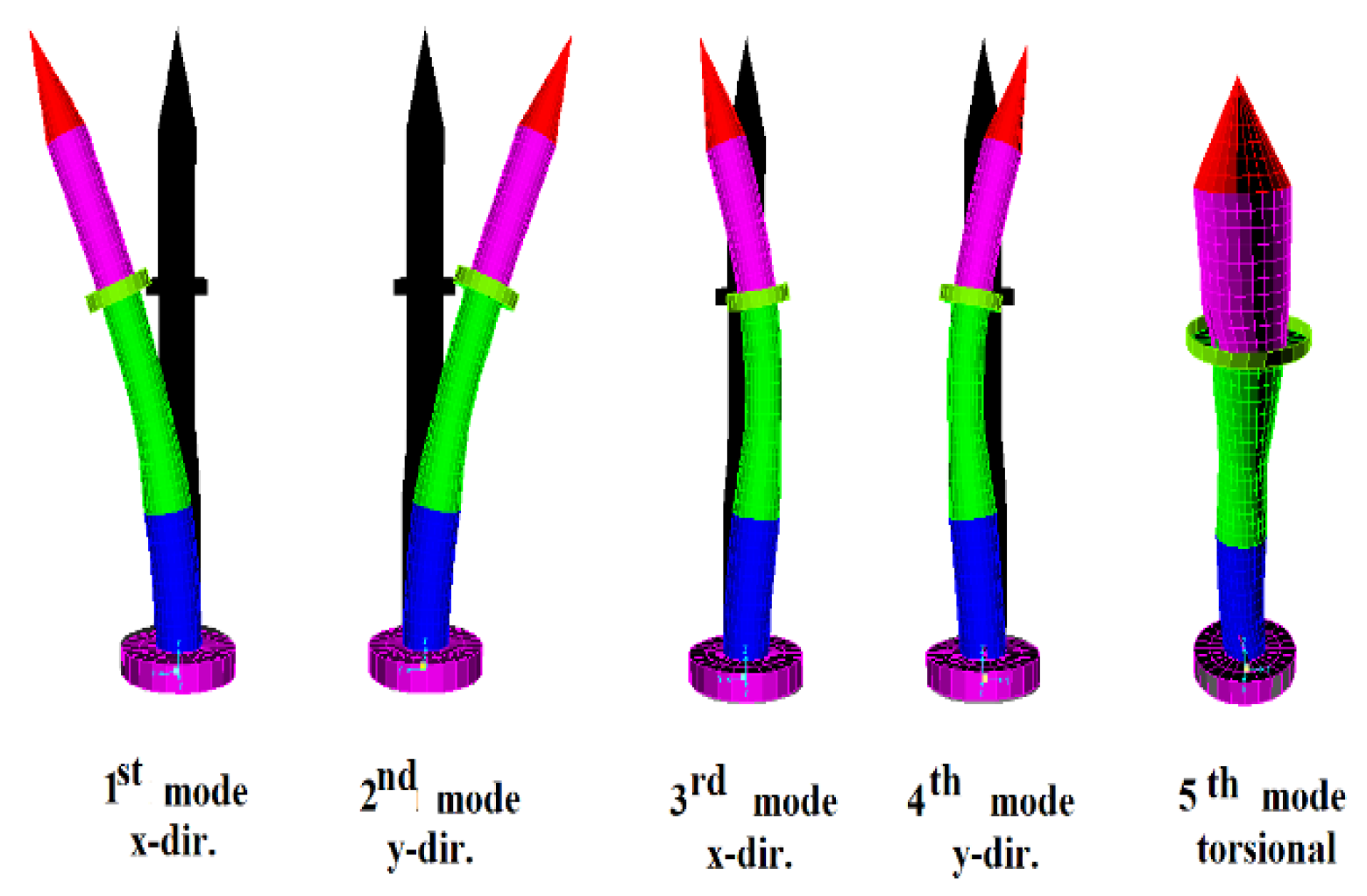
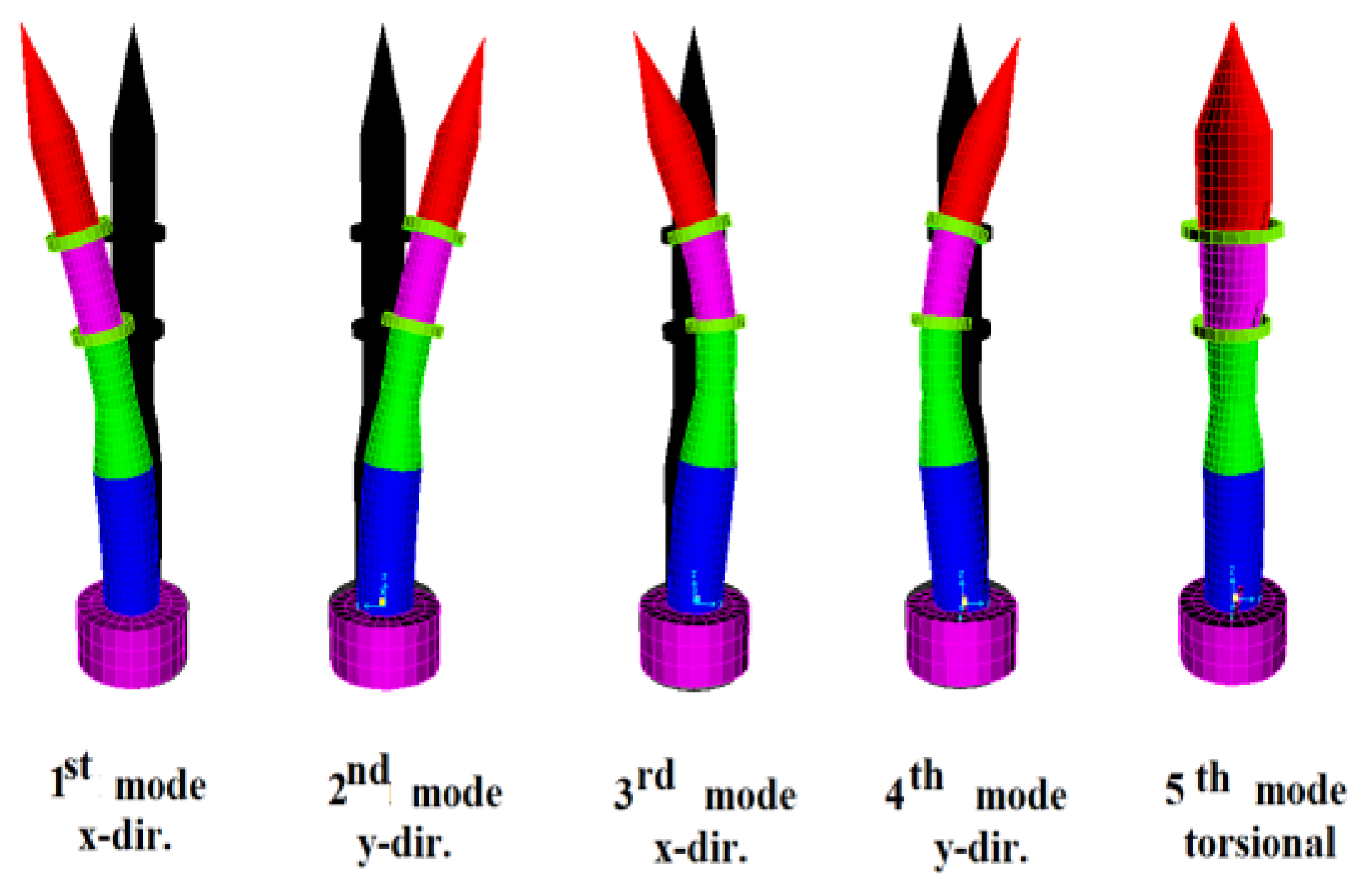
3.1. First-Mode Periods and Modal Participating Mass Ratios

The first-mode periods of the representative minarets are considered to be the dominant ones. Therefore, the first-mode periods for the fixed and for the Burman et al. method [44] of the representative models are given in Table 2.
Table 2 is given graphically in Figure 8. It is clear from Table 2 and Figure 8 that as the height of the minaret increases, the first-mode period increases for all cases. Also, considering SSI in the dynamic analyses increased the first-mode periods of the representative minarets when compared with the fixed-base model. It illustrates how crucial it is to take SSI into account when analyzing the RC minarets’ dynamic seismic response.
Also, the maximum and minimum first-mode periods occurred on S3 (soft) and S1 (stiff) soil, respectively. For illustration, the mode shapes of the representative minarets are given in Figure 9, Figure 10 and Figure 11.
The first four mode shapes for the representative minarets under consideration are in the x and y directions, whereas the fifth mode is torsional, as seen in Figure 9, Figure 10 and Figure 11. Also, the cumulative sum of modal participating mass ratios for the first nine modes are provided in Table 3.

3.2. Seismic Analysis

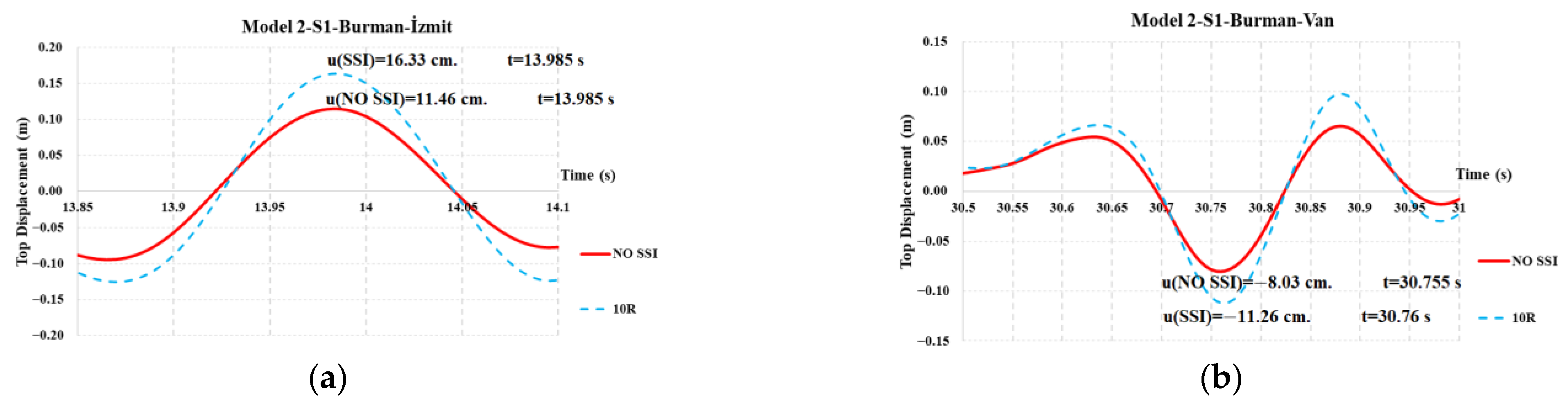
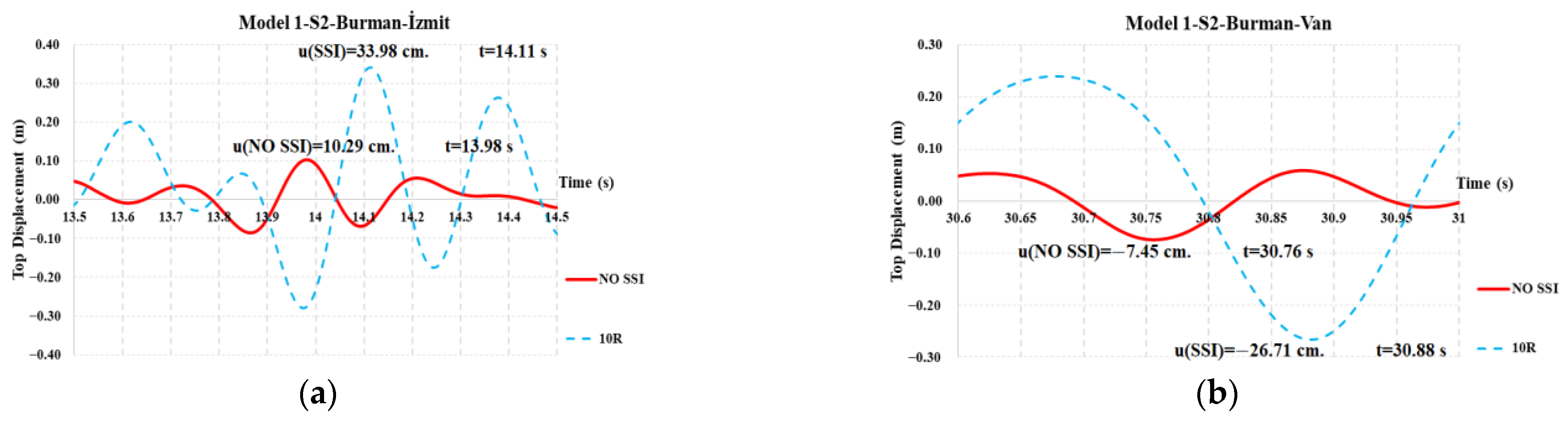
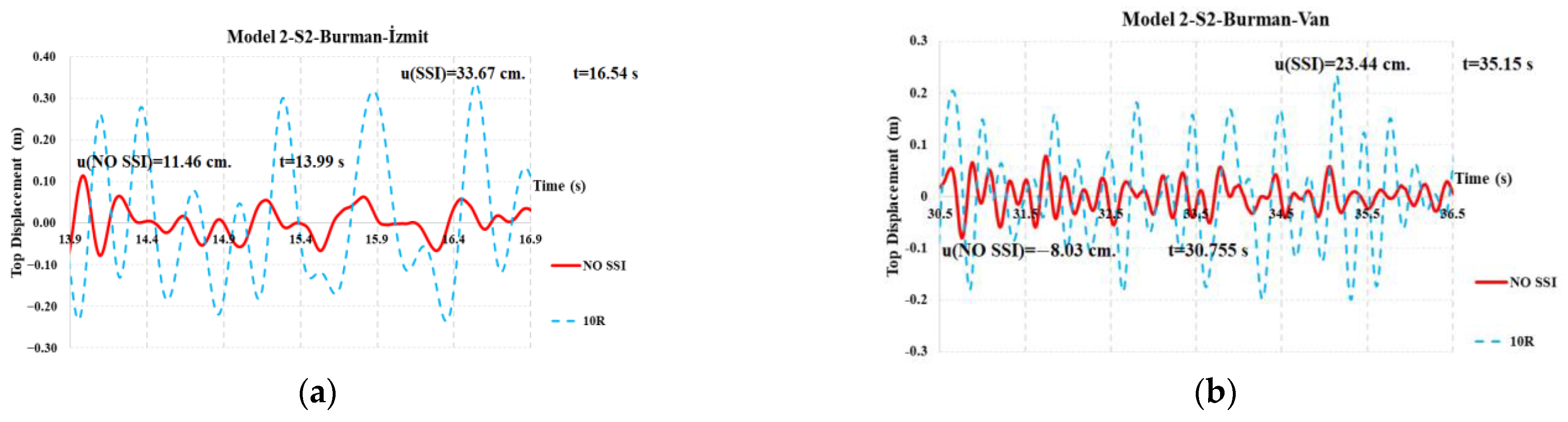
3.2.1. The Effect of SSI

The top displacements of the structure are another significant characteristic that needs to be considered while analyzing the dynamic seismic response of RC minarets. This section of the study represents the top displacements of the representative minarets under the Van and İzmit earthquakes for various soil types. For the S1 (stiff) type of soil, the top displacements for the representative minarets are given in Figure 12, Figure 13 and Figure 14. Additionally, the full durations of the listed earthquakes are not shown in the following figures due to the impossibility of obtaining both visible and feasible comparisons. As a result, only the effective duration intervals that produce the greatest response for the representative minarets as determined by the Burman et al. [44] method are displayed.
From the interpretation of Figure 12, Figure 13 and Figure 14, for all representative minarets, considering SSI in the dynamic response of RC minarets increased the top displacements when compared to considering the fixed-base (no SSI) model. Also, as can be clearly seen from the figures, the maximum responses for SSI and the fixed-base model approximately occurred at the same time interval. For example, for Model 3, under the İzmit earthquake (Figure 14a), the maximum responses occurred at the time of approximately 14.00 s.
The second type of soil that is considered is the S2 (medium) type of soil on the dynamic response of representative RC minarets. For the S2 (medium) type of soil, the top displacements for the representative minarets are given in Figure 15, Figure 16 and Figure 17.
From the interpretation of Figure 15, Figure 16 and Figure 17, it can be clearly seen that for all models considered, the top displacements obtained by considering the effect of SSI provided higher values when compared to the fixed (No SSI) models. This shows the importance of considering the effect of SSI on the dynamic seismic response of RC minarets. Also, for all models and earthquakes considered, in the S2 (medium) soil type, maximum top displacements happened at different time intervals, so it is not easy to predict the occurrence time of the maximum response. However, in the S1 (stiff) soil type, as it is emphasized in the preceding part of the study, the maximum top displacement responses for SSI and the fixed-base model approximately occurred at the same time interval, and making predictions of the occurrence time of the maximum top response became possible.
For the S3 (soft) type of soil, the top displacements for the representative minarets are given in Figure 18, Figure 19 and Figure 20.
Moreover, for all models considered, the İzmit earthquake created higher top displacement demands when compared with the ones obtained from the Van earthquake. This clearly indicates the effect of acceleration that is created from the earthquake. The other subject is considering SSI on the dynamic seismic response of RC minarets, which increased the top displacements when compared with the fixed-base model. This demonstrated how crucial it is to take SSI into account while analyzing RC minaret dynamic seismic response.

3.2.2. The Effect of Soil Type

The first subject that is determined in this part of the study is the effect of changing the type of soil from the stiff (S1) type of soil to the soft (S3) type of soil. For all models considered, the graphs of this change are obtained and given in Figure 21, Figure 22 and Figure 23 for the Burman et al. method [44].
From the interpretation of Figure 21, Figure 22 and Figure 23, for all representative minarets considered and for all earthquakes applied, as the soil gets softer from stiff (S1) to soft (S3), the top displacements increase as expected. This shows the importance of taking SSI into account in the dynamic seismic response of RC minarets. Also, the maximum top displacement demands become unpredictable as the soil becomes softer. Also, it can be useful to emphasize that the dynamic seismic analyses performed in this study were in the linear range. Therefore, it is very normal for top displacements to occur more often than the tolerable limits. In real-life situations, such top displacement values can cause brittle failure or high damage of the structure.
Also, in Figure 24, Figure 25 and Figure 26, at the time of maximum response, the displacement demands along the height of the minarets are provided (for different soil conditions).
From Figure 24, Figure 25 and Figure 26, it can be clearly seen that the largest displacements occurred at the top of the minarets, with the deformed shapes exhibiting a flexure-dominated behavior.

3.2.3. Stress Distributions

From the preceding part of the study, it was determined that the maximum top displacement occurred for Model 2 with the S3 soil type under the İzmit earthquake. Therefore, as an example, the distribution of the Smax and Smin values over the height of the cited minaret (for Model 2 with the S3 type soil under the İzmit earthquake) is given in Figure 27 and Figure 28, respectively.
From the interpretation of Figure 27 and Figure 28, it can be clearly identified that the Smax and Smin values were obtained only a little amount above the transition segment. To say it simply, the point of attachment, or the point where the transition segment and cylindrical body combine, is where the Smax and Smin values were accumulated.
As cited in the introduction part of this study and as can be clearly seen from Figure 27 and Figure 28, the vast majority of RC minarets collapsed or were subjected to brittle failure in the region, as given in Figure 29 [46], where fatal stress accumulations occurred.
This reveals that a large proportion of RC minarets failed during the most recent earthquakes. The weak junction point (between the transition segment and cylindrical body) suffered from the lateral displacement and showed brittle behavior instead of showing ductile behavior. Therefore, some extra precautions or protections should be executed.

3.3. Performance Evaluation

In the current technical literature, as specified in [18,30], there is no specialized design code or specification for the design or structural analysis for RC minarets, especially in the performance evaluation. Therefore, the design codes specialized for RC chimneys (tall and special structures like RC minarets) can be utilized in the design, structural analysis and performance evaluation of RC minarets. According to [47], in the section “Specific Rules for RC Chimneys”, it is stated that the requirement for damage limitation is considered to be satisfied if the lateral displacement of the top of the structure does not exceed 0.5% of the height of the structure. In this damage limitation state, permanent deformations of the structure are not desired. Also, without the need for structural repairs, the structural parts ought to maintain their original stiffness and strength. Moreover, for the models considered, the interstory drift ratios (IDRs) are obtained and provided in Table 4 in comparison with the damage limitation state value of 0.005.
As is performed in [48], the IDRs given in Table 4 are compared with each other. From this comparison, it can be clearly seen that the largest IDR is found to occur for Model 2 under the İzmit earthquake for the S3 type of soil. Also, for all models and earthquakes considered, from the fixed type of soil to the S3 type of soil, the value of IDRs increase, which shows the importance of considering SSI in the seismic behavior of RC minarets. Moreover, in [47], a limit of 0.005 is proposed for the damage limitation state. The IDRs for all models with the fixed type of soil under the Van earthquake satisfy the damage limit value proposed in [47]. Moreover, for the models considering SSI (except for Model 2 with the S1 soil type under the Van earthquake), the IDR values do not satisfy the damage limit value of 0.005, which shows the possibility of permanent damage occurring on the structures. This shows that it is very crucial for these types of tall and slender structures to take the SSI into account.

3.4. Precautions Suggested

From the findings of this study, some of the precautions to prevent the brittle failure of RC minarets are suggested as follows:
The first precaution that can be executed is the application of FRP to the cylindrical body of RC minarets. From the preceding studies conducted on the subject, FRP is proved to limit lateral displacement [16,49]. Also, there is a decrease in the Smax and Smin values that cause the brittle failure of the RC minaret. Furthermore, compared to RC minarets, FRP material can be used on RC chimneys that are extremely tall and thin [50]. Therefore, FRP can be effectively used in the representative minarets to decrease lateral top displacements and thus to decrease the Smax and Smin values.
The second precaution is the stiffening of soil with jet grouting. As can be deducted from the analysis results, as the soil gets softer from fixed to soft (S3) soil, the lateral displacements increased and the IDR limit value [47] was exceeded. Also, the Smax and Smin values increased when compared with the fixed-base model. This is fatal for RC minarets. Therefore, the soil should be strengthened to limit lateral displacements. Jet grouting can be effectively used to rehabilitate the soil without interrupting the structure [51,52]. It is very important to rehabilitate softer soil (S3) and transform it into stiff (S1) soil. Therefore, the jet grouting method can be effectively used for the representative minarets to rehabilitate the soil.
The third precaution is adapting buttresses to the body of RC minarets. In recent studies [32,53] performed on the subject, buttresses have been proved to limit lateral displacements and thus the Smax and Smin values of the structure. Thus, on model RC minarets, buttresses can be used successfully without interfering with any structural feature.

4. Conclusions

There are a lot of parameters affecting the dynamic seismic response of RC minarets, i.e., the structural properties of the RC minaret, the mechanical properties of the materials utilized, the SSI effect, etc. One of the most important one among these parameters is the SSI. In this study, in order to determine the effect of SSI, three different types of soils were analyzed by using the viscous boundary method proposed by Burman et al. [44] for three types of traditional representative RC minarets under the 17 August 1999 Mw 7.4 İzmit earthquake and the 23 October 2011 Mw 7.2 Van earthquake. The following are some conclusions drawn from this study:
  • As the soil gets softer from stiff (S1) to soft (S3), the first mode of the representative minarets and top displacement demands increased rapidly (Figure 8, Figure 21, Figure 22 and Figure 23), which shows the importance of considering SSI in the dynamic seismic analysis of RC minarets.
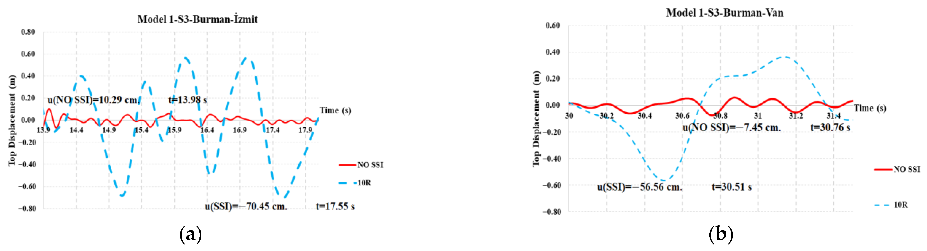
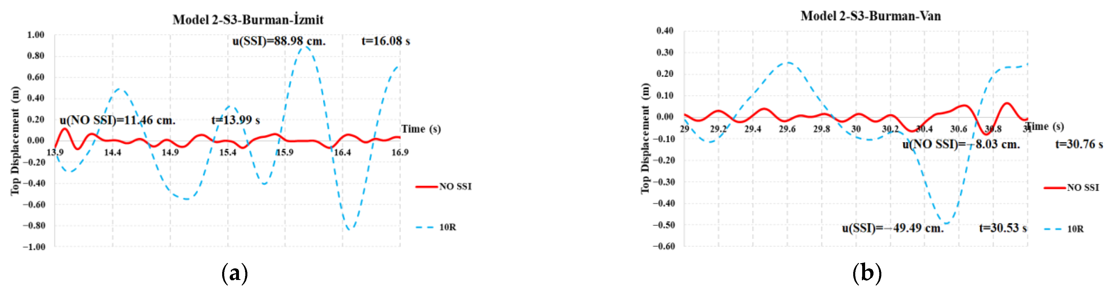
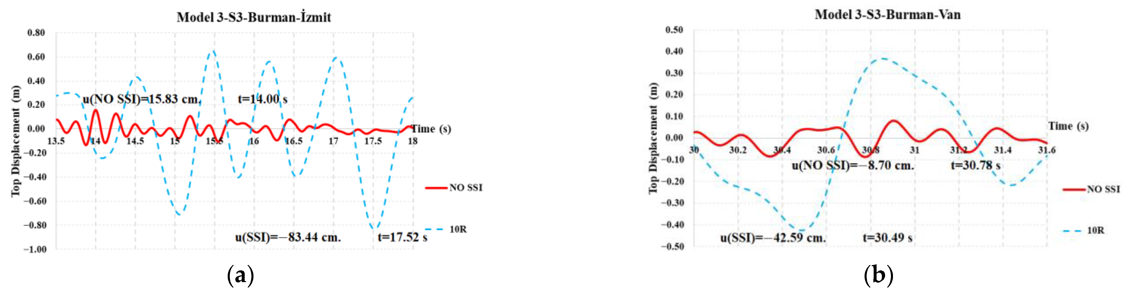
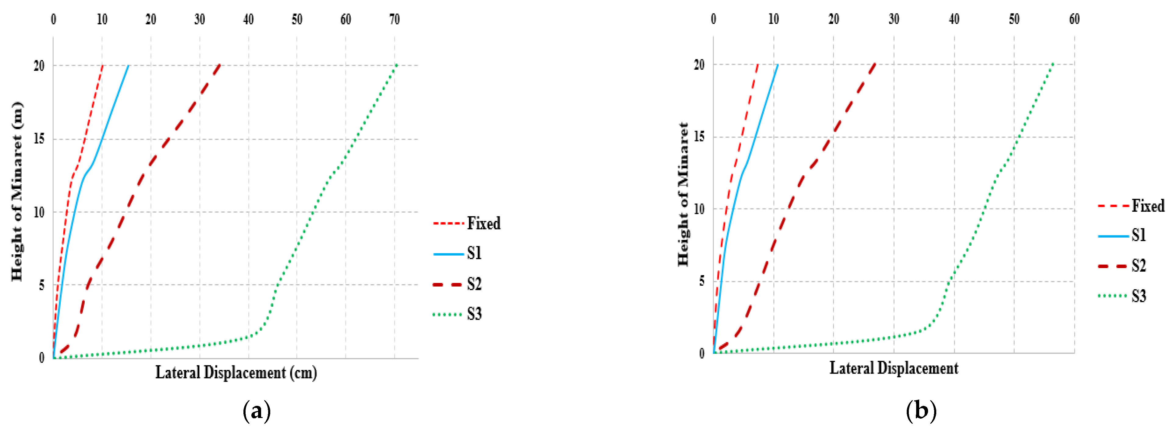
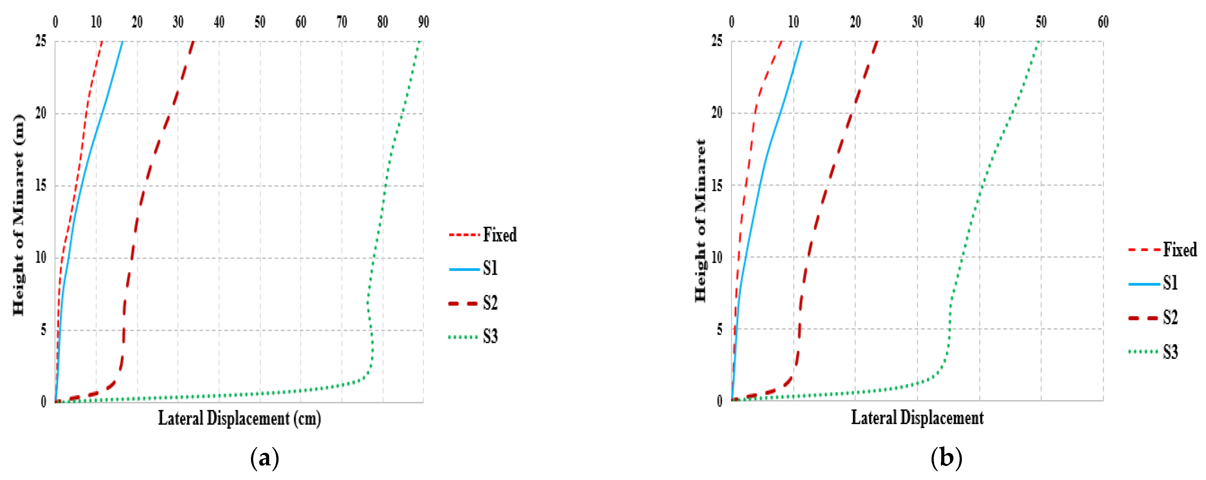
  • Even in the S1 type of soil compared to the fixed model, the top displacements increased rapidly, which shows the importance of considering SSI in the dynamic response of RC minarets. As the soil gets softer from the fixed S3 type of soil, the top displacements ascended and the related IDRs also increased.
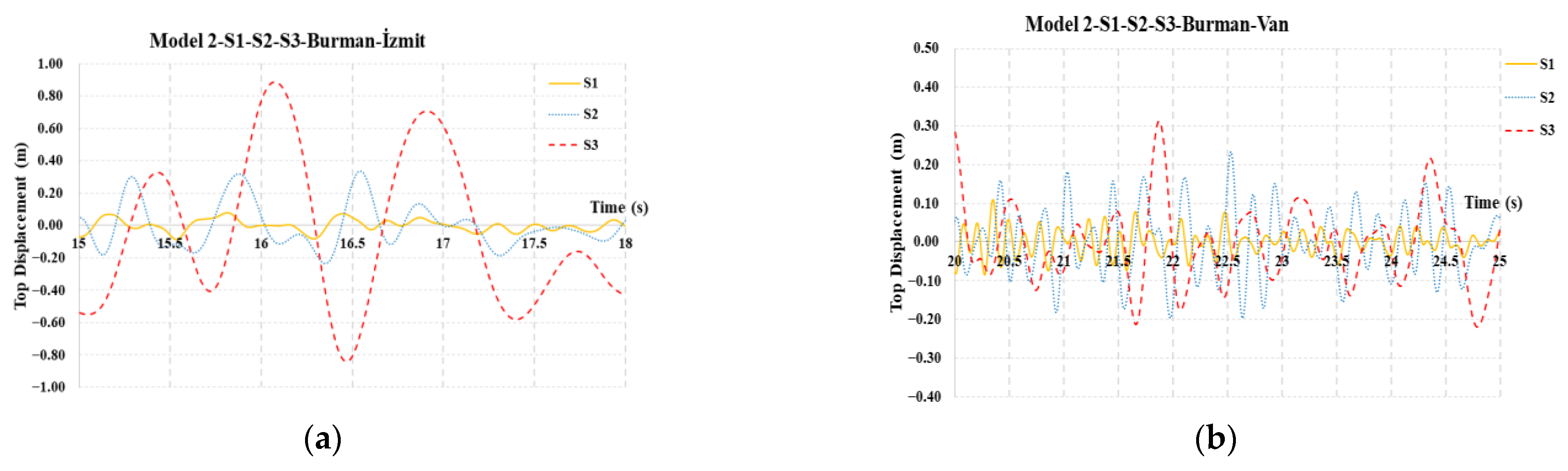
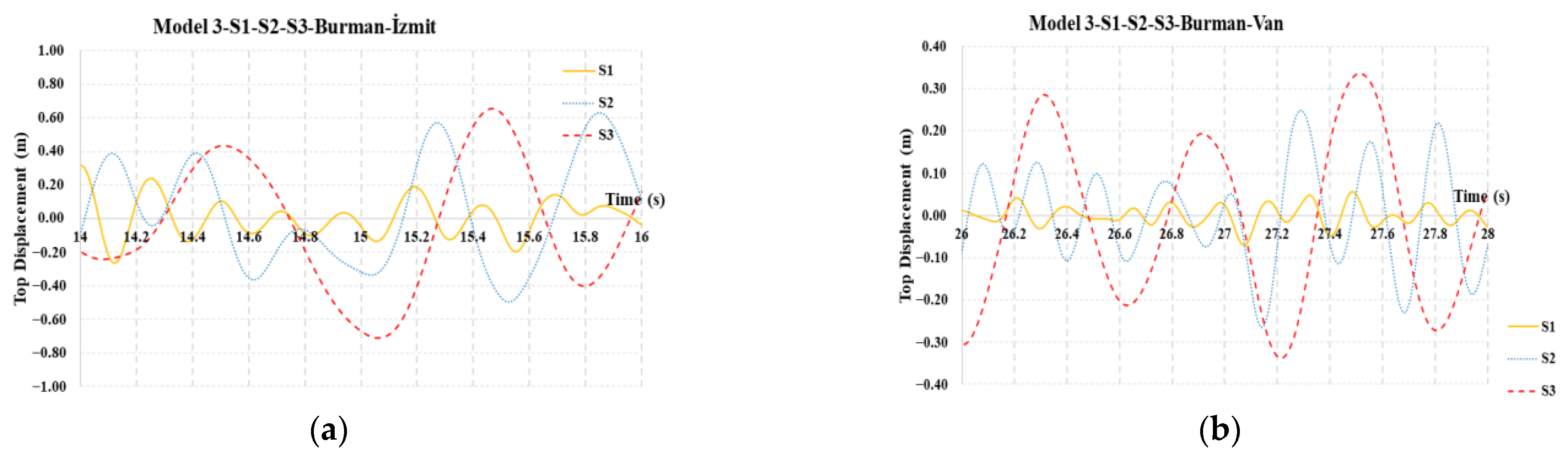
  • The structural behavior, i.e., top displacements of the representative minarets, are homogeneous when the soil type is stiff (S1), i.e., the maximum top displacements occurred approximately at the same time interval. Therefore, it is possible to predict the structural behavior of the representative minarets when the soil is stiffer. However, when the soil gets softer to the S2 or S3 type of soil, it becomes impossible to guess the structural behavior of the representative minarets i.e., the maximum top displacements did not occur at the same time interval when the time histories were explored.
  • For all models considered, the top displacement demands obtained from İzmit earthquake are higher compared to the top displacement demands obtained from the Van earthquake. This clearly shows the effect of acceleration created from the İzmit earthquake.
  • The maximum value of the IDR is obtained for Model 2 under the İzmit earthquake for the S3 type of soil. Additionally, the value of IDRs increases for all models and earthquakes investigated, ranging from the fixed type of soil to the S3 type of soil, indicating the need of taking SSI into account when analyzing the seismic behavior of RC minarets. The damage limit value of 0.005 is satisfied by the IDRs for all models under the Van earthquake that have a fixed type of soil. Furthermore, the IDR values for the models taking into account SSI (apart from Model 2 with the S1 soil type under the Van earthquake) do not fulfil the damage limit value of 0.005, which indicates the probability of irreversible damage to the structure. This demonstrates how important it is that the SSI be considered for these kinds of tall, thin and special structures.
  • The displacement demands along the height of the minarets increased from bottom to top as can be seen from the related figures (Figure 24, Figure 25 and Figure 26). Also, the maximum value of displacements are obtained at the top of the minarets by showing a flexure dominant behavior.
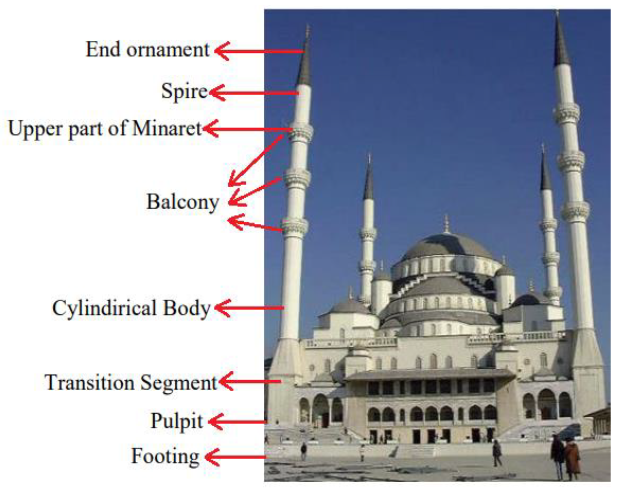
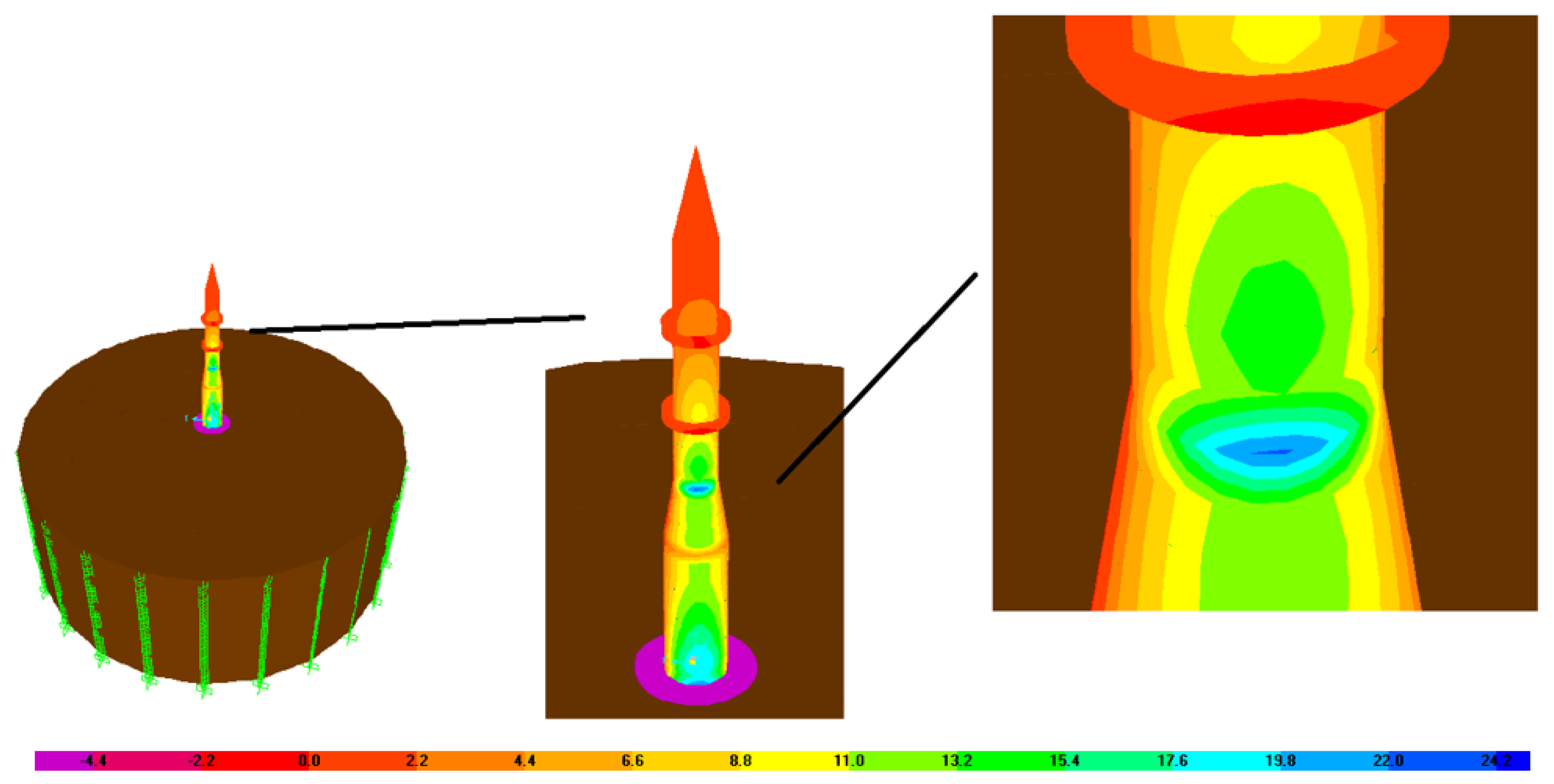
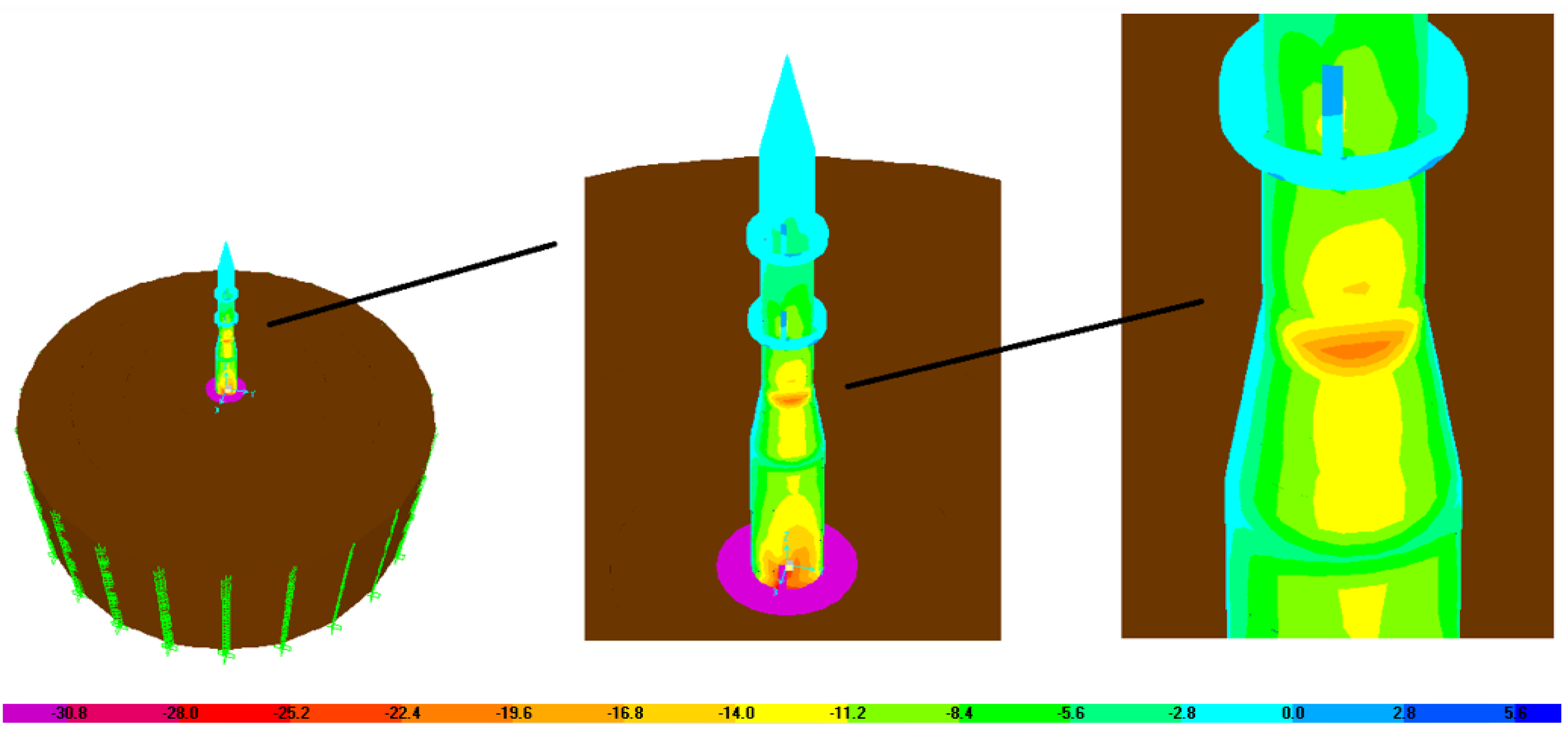
  • For the representative minarets considered, the maximum and minimum stress concentrations, Smax and Smin, are at the end of the transition segment. Stated differently, practically all investigations on the seismic behavior of minarets indicate that the main areas of stress concentration are between the transition segment and the main body of the minaret, even with linear models. By adding a buttressed element to the cross-section or wrapping FRP around the cylindrical body of the RC minaret, it is possible to significantly reduce the lateral displacement demands of the structural system and hence the values of Smax and Smin stresses that cause brittle failure.
  • As cited before, the jet grouting method is an effective way to improve the mechanical properties of the soil. In this way, the top displacements and stress distribution over RC minarets can be reduced to a tolerable limit.
In summary, this study represented the evaluation of a simplified method on the dynamic seismic responses of RC minarets considering the SSI effect. The findings of this study revealed that considering SSI in the dynamic response of RC minarets is crucial to determine the structural response as close to real behavior as possible. Therefore, in the design and analysis of RC minarets, it is suggested to consider the effect of SSI.

Funding

This research received no external funding.

Data Availability Statement

Data are contained within the article.

Conflicts of Interest

The author declares no conflicts of interest.

References

  1. Günaydın, M.; Tonyalı, Z. Dynamic response of a reinforced concrete minaret. J. Struct. Eng. Appl. Mech. 2018, 1, 62–72. [Google Scholar] [CrossRef]
  2. Erdik, M.; Biro, Y.A.; Onur, T.; Sesetyan, K.; Birgoren, G. Assessment of earthquake hazard in Turkey and neighboring regions. Ann. Geophys. 1999, 42, 1125–1138. [Google Scholar] [CrossRef]
  3. Gülkan, P.; Kalkan, E. Attenuation modeling of recent earthquakes in Turkey. J. Seismol. 2002, 6, 397–409. [Google Scholar] [CrossRef]
  4. Tan, O.; Tapirdamaz, M.C.; Yörük, A. The earthquake catalogues for Turkey. Turk. J. Earth Sci. 2008, 17, 405–418. [Google Scholar]
  5. Ersoy, Ş.; Gürüm, T. 23 October 2011 Geological and Geomorphological Preliminary Evaluation Report on Van Earthquake (Mw 7.2); Department of Earthquake Engineering, Boğaziçi University: İstanbul, Turkey, 2011. [Google Scholar]
  6. Şanlı, A.; Utkucu, M.; Yalçın, H. A finite fault model of the March 13, 1992 Erzincan (Mw = 6.8) from the inversion of teleseismic P and SH waveforms. In Proceedings of the 4th International Conference on Earthquake Engineering and Seismology, Eskişehir, Turkey, 10–13 October 2017. [Google Scholar]
  7. AFAD. Available online: https://deprem.afad.gov.tr/assets/pdf/deprem-bilgi-destek-sistemi.pdf (accessed on 10 May 2023).
  8. Sezen, H.; Fırat, G.Y.; Sözen, M.A. Investigation of the performance of monumental structures during the 1999 Kocaeli and Düzce earthquakes. In Proceedings of the 5th National Conference on Earthquake Engineering, İstanbul, Turkey, 26–30 May 2003. [Google Scholar]
  9. Doğangün, A.; Acar, R.; Livaoğlu, R.; Tuluk, Ö.İ. Performance of masonry minarets against earthquakes and winds in Turkey. In Proceedings of the 1st International Conference on Restoration of Heritage Masonry Structures, Cairo, Egypt, 24–27 April 2006. [Google Scholar]
  10. Doğangün, A.; Sezen, H.; Tuluk, Ö.İ.; Livaoğlu, R.; Acar, R. Traditional Turkish masonry monumental structures and their earthquake response. Int. J. Archit. Herit. 2007, 1, 251–271. [Google Scholar] [CrossRef]
  11. Acar, R.; Livaoglu, R.; Dogangun, A.; Sezen, H. The effects of subsoils on the seismic response of reinforced concrete cylindrical minarets. In Proceedings of the 5th International Conference on Seismology and Earthquake Engineering, Tehran, Iran, 13–16 May 2007. [Google Scholar]
  12. Doğangün, A.; Acar, R.; Sezen, H.; Livaoglu, R. Investigation of dynamic response of masonry minaret structures. Bull. Earthq. Eng. 2008, 6, 505–517. [Google Scholar] [CrossRef]
  13. Doğangün, A.; Sezen, H. Seismic vulnerability and preservation of historical masonry monumental structures. Earthq. Struct. 2012, 3, 83–95. [Google Scholar] [CrossRef]
  14. Sezen, H.; Dogangun, A. Seismic performance of historical and monumental structures. In Earthquake Engineering; InTech: London, UK, 2012. [Google Scholar]
  15. Oliveira, C.S.; Çaktı, E.; Stengel, D.; Branco, M. Minaret behavior under earthquake loading: The case of historical Istanbul. Earthq. Eng. Struct. Dyn. 2012, 41, 19–39. [Google Scholar] [CrossRef]
  16. Türk, A.M. Seismic response analysis of masonry minaret and possible strengthening by fiber reinforced cementitious matrix (FRCM) materials. Adv. Mater. Sci. Eng. 2013, 2013, 952497. [Google Scholar] [CrossRef]
  17. URL-1. Available online: https://www.trthaber.com/haber/turkiye/adiyamanda-minare-binayi-ikiye-boldu-749846.html (accessed on 10 May 2023).
  18. Sezen, H.; Acar, R.; Dogangun, A.; Livaoglu, R. Dynamic analysis and seismic performance of reinforced concrete minarets. Eng. Struct. 2008, 30, 2253–2264. [Google Scholar] [CrossRef]
  19. Pak, R.Y.S.; Guzina, B.B. Seismic soil-structure interaction analysis by direct boundary element methods. Int. J. Solids Struct. 1999, 36, 4743–4766. [Google Scholar] [CrossRef]
  20. Yazdchi, M.; Khalili, N.; Valliappan, S. Dynamic soil–structure interaction analysis via coupled finite-element–boundary-element method. Soil Dyn. Earthq. Eng. 1999, 18, 499–517. [Google Scholar] [CrossRef]
  21. Mylonakis, G.; Gazetas, G. Seismic soil-structure interaction: Beneficial or detrimental? J. Earthq. Eng. 2000, 4, 277–301. [Google Scholar] [CrossRef]
  22. Tabatabaiefar, H.R.; Massumi, A. A simplified method to determine seismic responses of reinforced concrete moment resisting building frames under influence of soil–structure interaction. Soil Dyn. Earthq. Eng. 2010, 30, 1259–1267. [Google Scholar] [CrossRef]
  23. Lai, C.G.; Menon, A.; Macchi, G. Seismic vulnerability of the minaret of Jam in Afghanistan. In Proceedings of the XI National Congress of Seismic Engineering, Genoa, Italy, 25–29 January 2004. [Google Scholar]
  24. Doğangün, A.; Livaoğlu, R.; Acar, R. A study on seismic behavior of minarets considering soil-structure interaction. In Proceedings of the International Earthquake Symposium, Kocaeli, Turkey, 22–26 October 2007. [Google Scholar]
  25. Doğangün, A.; Tuluk, Ö.İ.; Livaoğlu, R.; Acar, R. Traditional Turkish minarets on the basis of architectural and engineering concepts. In Proceedings of the 1st International Conference on Restoration of Heritage Masonry Structures, Cairo, Egypt, 24–27 April 2006. [Google Scholar]
  26. Örmecioglu, H.T.; Aslı, E.R.; Beeson, S.T.; Özmen, C. Structural analysis and seismic behavior of Yivli Minaret. Süleyman Demirel Univ. Int. J. Tech. Sci. 2011, 3, 52–61. [Google Scholar]
  27. Cosgun, C.; Türk, A.M. Seismic behaviour and retrofit of historic masonry minaret. Građevinar 2011, 64, 39–45. [Google Scholar] [CrossRef]
  28. Mortezaei, A.; Kheyroddin, A.; Ronagh, H.R. Finite element analysis and seismic rehabilitation of a 1000-year-old heritage listed tall masonry mosque. Struct. Des. Tall Spec. 2012, 21, 334–353. [Google Scholar] [CrossRef]
  29. Pekgökgöz, R.K.; Gürel, M.A.; Mammadov, Z.; Çili, F. Dynamic analysis of vertically post-tensioned masonry minarets. J. Earthq. Eng. 2013, 17, 560–589. [Google Scholar] [CrossRef]
  30. Türkeli, E. Determination and comparison of wind and earthquake responses of reinforced concrete minarets. Arab. J. Sci. Eng. 2014, 39, 3665–3680. [Google Scholar] [CrossRef]
  31. Clemente, P.; Saitta, F.; Buffarini, G.; Platania, L. Stability and seismic analyses of leaning towers: The case of the minaret in Jam. Struct. Des. Tall Spec. 2015, 24, 40–58. [Google Scholar] [CrossRef]
  32. Türkeli, E.; Livaoğlu, R.; Doğangün, A. Dynamic response of traditional and buttressed reinforced concrete minarets. Eng. Fail. Anal. 2015, 49, 31–48. [Google Scholar] [CrossRef]
  33. Ural, A.; Firat, F.K. Evaluation of masonry minarets collapsed by a strong wind under uncertainty. Nat. Hazards 2015, 76, 999–1018. [Google Scholar] [CrossRef]
  34. Başaran, H.; Demir, A.; Ercan, E.; Nohutcu, H.; Hökelekli, E.; Kozanoğlu, C. Investigation of seismic safety of a masonry minaret using its dynamic characteristics. Earthq. Struct. 2016, 10, 523–538. [Google Scholar] [CrossRef]
  35. Erdoğan, Y.S.; Kocatürk, T.; Demir, C. Investigation of the seismic behavior of a historical masonry minaret considering the interaction with surrounding structures. J. Earthq. Eng. 2017, 23, 112–140. [Google Scholar] [CrossRef]
  36. Hacıefendioğlu, K.; Alpaslan, E.; Demir, G.; Dinç, B.; Birinci, F. Experimental modal investigation of scaled minaret embedded in different soil types. Građevinar 2018, 70, 201–212. [Google Scholar]
  37. Altun, N. Project of the Concrete Minarets Considering the Soil-Structure Interaction in the Light of 2007 and 2018 Earthquake Regulations. Master’s Thesis, Ondokuz Mayıs University, Samsun, Turkey, 2019. [Google Scholar]
  38. Türkeli, E. Comparative dynamic seismic analyses of RC minarets strengthened with FRP and buttresses. J. Nat. Hazard Environ. 2020, 6, 119–136. [Google Scholar] [CrossRef]
  39. Wilson, E.L. SAP 2000: Integrated Finite Element Analysis and Design of Structures; Computers & Structures: Berkeley, CA, USA, 2000. [Google Scholar]
  40. Livaoğlu, R.; Doğangün, A. Effect of foundation embedment on seismic behavior of elevated tanks considering fluid–structure-soil interaction. Soil Dyn. Earthq. Eng. 2007, 27, 855–863. [Google Scholar] [CrossRef]
  41. Lysmer, J.; Kuhlemeyer, R.L. Finite dynamic model for infinite media. J. Eng. Mech. Div. 1969, 95, 859–878. [Google Scholar] [CrossRef]
  42. Livaoglu, R.; Cakir, T.; Dogangun, A.; Aytekin, M. Effects of backfill on seismic behavior of rectangular tanks. Ocean Eng. 2011, 38, 1161–1173. [Google Scholar] [CrossRef]
  43. Bao, H.; Hatzor, Y.H.; Huang, X. A new viscous boundary condition in the two-dimensional discontinuous deformation analysis method for wave propagation problems. Rock. Mech. Rock. Eng. 2012, 45, 919–928. [Google Scholar] [CrossRef]
  44. Burman, A.; Nayak, P.; Agrawal, P.; Maity, D. Coupled gravity dam–foundation analysis using a simplified direct method of soil–structure interaction. Soil Dyn. Earthq. Eng. 2012, 34, 62–68. [Google Scholar] [CrossRef]
  45. URL-2. Available online: https://tadas.afad.gov.tr/login (accessed on 16 March 2023).
  46. URL-3. Available online: https://dogruhaber.com.tr/haber/909777-depremde-yikilan-minare-3-katli-apartmanin-uzerine-tek-parca-seklinde-devrildi/ (accessed on 23 April 2024).
  47. EN 1998-6 (2005); Eurocode 8: Design of Structures for Earthquake Resistance-Part 6: Towers, Masts and Chimneys. Comite Europeen De Normalisation: Brussels, Belgium, 2005.
  48. Shabani, A.; Feyzabadi, M.; Kioumarsi, M. Model updating of a masonry tower based on operational modal analysis: The role of soil-structure interaction. Case Stud. Constr. Mater. 2022, 16, e00957. [Google Scholar] [CrossRef]
  49. Altunişik, A.C. Dynamic response of masonry minarets strengthened with Fiber Reinforced Polymer (FRP) composites. Nat. Hazard Earth Sys. 2011, 11, 2011–2019. [Google Scholar] [CrossRef]
  50. Karaca, Z.; Türkeli, E.; Günaydın, M.; Adanur, S. Dynamic responses of industrial reinforced concrete chimneys strengthened with fiber-reinforced polymers. Struct. Des. Tall Spec. Build. 2015, 24, 228–241. [Google Scholar] [CrossRef]
  51. Karahan, G.N.; Sivrikaya, O. Designing singular jet grouting column for sandy soils. Environ. Earth Sci. 2018, 77, 448. [Google Scholar] [CrossRef]
  52. Güllü, H. A novel approach to prediction of rheological characteristics of jet grout cement mixtures via genetic expression programming. Neural Comput. Appl 2017, 28, 407–420. [Google Scholar] [CrossRef]
  53. Doğangün, A.; Acar, R.; Livaoglu, R.; Sezen, H. Comparison of structural response of traditional and strengthened reinforced concrete minarets. In Proceedings of the 5th International Conference on Seismology and Earthquake Engineering, Tehran, Iran, 13–16 May 2007. [Google Scholar]
Figure 1. The main parts of an RC minaret [1].
Buildings 14 01796 g001
Figure 2. Finite element models of Model 1.
Buildings 14 01796 g002
Figure 3. Finite element models of Model 2.
Buildings 14 01796 g003
Figure 4. Finite element models of Model 3.
Buildings 14 01796 g004
Figure 5. Essential geometric characteristics of minarets.
Buildings 14 01796 g005
Figure 6. Time histories of earthquakes (a) 17 August 1999 İzmit earthquake (b) 23 October 2011 Van earthquake.
Buildings 14 01796 g006
Figure 7. Representation of the viscous boundaries at the end of the soil.
Buildings 14 01796 g007
Figure 8. First-mode periods of models for various types of soils.
Buildings 14 01796 g008
Figure 9. First five mode shapes of Model 1.
Buildings 14 01796 g009
Figure 10. First five mode shapes of Model 2.
Buildings 14 01796 g010
Figure 11. First five mode shapes of Model 3.
Buildings 14 01796 g011
Figure 12. Top displacements of Model 1 for stiff soil: (a) İzmit earthquake and (b) Van earthquake.
Buildings 14 01796 g012
Figure 13. Top displacements of Model 2 for stiff soil: (a) İzmit earthquake and (b) Van earthquake.
Buildings 14 01796 g013
Figure 14. Top displacements of Model 3 for stiff soil: (a) İzmit earthquake and (b) Van earthquake.
Buildings 14 01796 g014
Figure 15. Top displacements of Model 1 for medium soil: (a) İzmit earthquake and (b) Van earthquake.
Buildings 14 01796 g015
Figure 16. Top displacements of Model 2 for medium soil: (a) İzmit earthquake and (b) Van earthquake.
Buildings 14 01796 g016
Figure 17. Top displacements of Model 3 for medium soil: (a) İzmit earthquake and (b) Van earthquake.
Buildings 14 01796 g017
Figure 18. Top displacements of Model 1 for soft soil: (a) İzmit earthquake and (b) Van earthquake.
Buildings 14 01796 g018
Figure 19. Top displacements of Model 2 for soft soil: (a) İzmit earthquake and (b) Van earthquake.
Buildings 14 01796 g019
Figure 20. Top displacements of Model 3 for soft soil: (a) İzmit earthquake (b) Van earthquake.
Buildings 14 01796 g020
Figure 21. Change in soil from S1 to S3 for Model 1: (a) İzmit earthquake and (b) Van earthquake.
Buildings 14 01796 g021
Figure 22. Change in soil from S1 to S3 for Model 2: (a) İzmit earthquake and (b) Van earthquake.
Buildings 14 01796 g022
Figure 23. Change in soil from S1 to S3 for Model 3: (a) İzmit earthquake and (b) Van earthquake.
Buildings 14 01796 g023
Figure 24. Displacement demands along the height of Model 1 for different soil conditions. (a) İzmit earthquake and (b) Van earthquake.
Buildings 14 01796 g024
Figure 25. Displacement demands along the height of Model 2 for different soil conditions. (a) İzmit earthquake and (b) Van earthquake.
Buildings 14 01796 g025
Figure 26. Displacement demands along the height of Model 3 for different soil conditions. (a) İzmit earthquake and (b) Van earthquake.
Buildings 14 01796 g026
Figure 27. Smax (tensile) (MPa) contours for Model 2 with S3 soil type under İzmit earthquake at the time of maximum response.
Buildings 14 01796 g027
Figure 28. Smin (compressive) (MPa) contours for Model 2 with S3 soil type under İzmit earthquake at the time of maximum response.
Buildings 14 01796 g028
Figure 29. RC minaret fracture brittle right above the transition segment [46].
Buildings 14 01796 g029
Table 1. Features of the three categories of soil under consideration [40].
Soil TypeE (kN/m2)γ (kg/m3)νvs (m/s)vp (m/s)
S17,000,00020000.31149.12149.89
S2500,00019000.35309.22643.68
S375,00018000.4120.82295.95
Table 2. First-mode periods (in s) of the representative minarets for different soil types.
With SSI
Model 1Fixed0.214933-
S1-0.218611
S2-0.412332
S3-1.029321
Model 2Fixed0.21815-
S1-0.218475
S2-0.523131
S3-1.29032
Model 3Fixed0.235511-
S1-0.236422
S2-0.608591
S3-1.44093
Table 3. Cumulative sum of modal participating mass ratios for the first nine modes.
Model NoFirst ModeSecond ModeThird ModeFourth ModeFifth ModeSixth ModeSeventh ModeEighth ModeNinth Mode
Model 10.300.310.450.450.450.450.510.510.51
Model 20.100.100.160.160.160.160.190.190.19
Model 30.150.150.240.240.240.240.240.240.27
Table 4. IDRs for different models under different earthquakes with different soil types.
Model NoSoil TypeEarthquake DataΔi (cm)hi (m)Δi/hiDamage Limitation State (0.5% or 0.005) [47]
Model 1Fixedİzmit10.29200.00514X
Van7.45200.00372
S1İzmit15.39200.00769X
Van10.70200.00535X
S2İzmit33.98200.01699X
Van26.71200.01335X
S3İzmit70.45200.03522X
Van56.56200.02828X
Model 2Fixedİzmit11.46250.00458
Van8.03250.00321
S1İzmit16.33250.00653X
Van11.26250.00450
S2İzmit33.67250.01346X
Van23.44250.00937X
S3İzmit88.98250.03559X
Van49.49250.01979X
Model 3Fixedİzmit15.83290.00545X
Van8.70290.00300
S1İzmit31.38290.01082X
Van16.33290.00563X
S2İzmit88.88290.03064X
Van72.40290.02496X
S3İzmit83.44290.02877X
Van42.59290.01468X
Disclaimer/Publisher’s Note: The statements, opinions and data contained in all publications are solely those of the individual author(s) and contributor(s) and not of MDPI and/or the editor(s). MDPI and/or the editor(s) disclaim responsibility for any injury to people or property resulting from any ideas, methods, instructions or products referred to in the content.

