Abstract
The sleeve grouting connection is the most common form of vertical connection for prefabricated shear walls. However, during construction, this type of connection is prone to defects such as insufficient anchorage length of reinforcement, deviation of reinforcement, and insufficient amount of sleeve grouting, which significantly impact the integrity and seismic performance of the prefabricated shear wall structure. The finite element analysis of the prefabricated shear wall with sleeve grouting connection is still based on solid element modeling. This method has the disadvantages of complex models and low computational efficiency. In this paper, a simplified modeling method for prefabricated shear walls considering sleeve grouting defects was proposed to address this issue. Firstly, the equivalent constitutive relationship of the sleeve grouting defect connector was constructed based on the uniaxial tensile test of the existing sleeve grouting defect connector, and the T3D2 element was used to simulate the sleeve grouting connector. Then, the mechanical behavior of the horizontal joint between the shear wall and the foundation beam was simulated by the cohesive force model, and the prefabricated shear wall models with sleeve grouting defects were established. The accuracy of the simplified modeling method was verified by comparing the experimental results and numerical simulation results of the seismic performance of the prefabricated shear wall with sleeve grouting defects. The results showed that the hysteresis curve, skeleton curve, and failure mode of the numerical simulation were in good agreement with the test results. However, the stiffness of the concrete degenerated rapidly due to the apparent development of plastic-damaged concrete, which made the falling section of the hysteresis curve of the numerical simulation different from that of the test. The proposed simplified modeling method can be further applied to the performance study of prefabricated shear walls with sleeve grouting defects and can provide a reference for structural performance evaluation, design optimization, and construction quality control to a certain extent.
1. Introduction
Prefabricated building refers to producing prefabricated components in the factory and delivering components to the construction site for assembly, connection, and installation [1]. At present, in medium and high-rise buildings, especially residential buildings, prefabricated shear wall structure is widely used as an essential lateral force-resisting component. However, its structural integrity is easily restricted by horizontal and vertical joints, resulting in stiffness mutation, discontinuous deformation, and stress concentration, which will affect the integrity and seismic performance of the structure. Therefore, if the prefabricated shear wall structure is to achieve ‘equivalent cast-in-place’, the connection mode and quality of the joints will be crucial.
The vertical connection between the prefabricated shear wall components mainly adopts the sleeve grouting connection. This connection method is achieved by inserting two steel reinforcements into the connector and injecting grouting material. When the grouting material hardens, steel reinforcements and sleeve connectors are firmly combined. It has the characteristics of clear force, good deformation performance, convenient construction, and high reliability, which has attracted the attention of many scholars. Hayashi [2] and Eniea et al. [3] studied the factors affecting the mechanical properties of sleeve grouting connectors and deduced the calculation formula of bond strength of sleeve grouting reinforcement. Koushfar [4] conducted a uniaxial tensile test on the sleeve grouting joint of the new glass fiber-reinforced polymer grouting material and studied the bond stress slip law based on the test results. Ling et al. [5,6] carried out an incremental tensile test on the sleeve grouting steel bar connector until the specimen was destroyed and found that the geometry of the sleeve had a significant effect on the bonding performance. Zhang [7] studied the influence of different anchorage lengths on the sleeve grouting connector under uniaxial load by the uniaxial tensile test of fiber-reinforced grouting material grouting sleeve connector. Liu [8] studied the failure process of sleeve grouting connectors under uniaxial tensile load by the uniaxial tensile test of sleeve grouting connectors and finite element analysis of the uniaxial tensile test.
Based on the experimental research on the mechanical properties of the sleeve grouting connection, some scholars have also researched the sleeve grouting connection prefabricated shear wall. Ling [9] carried out tensile, shear, and bending load tests on the prefabricated shear walls connected by sleeve grouting until failure. According to the load-displacement curve, ultimate bearing capacity, and ductility response, the feasibility of the joint was evaluated. Du [10] and Min [11] conducted a horizontal reciprocating load test on the sleeve grouting short-leg prefabricated shear wall (PSSW). The results indicated that PSSW experienced bending failure and the sleeve grouting reinforcement connection is reliable. Lu [12] and Li [13] conducted low-cycle reciprocating load tests on L-shaped sleeve grouting prefabricated shear walls and cast-in-place shear walls. The results show that the bearing capacity of the prefabricated shear wall is slightly lower than that of the cast-in-place shear wall, but the deformation capacity and ductility are better, which proves that the prefabricated shear wall has good and reliable seismic performance. Peng [14,15] analyzed the quasi-static test of five shear walls with horizontal joints and vertical steel sleeve connections and four shear walls with slurry anchor connections. It was observed that the failure modes of both prefabricated wall specimens and cast-in-place wall specimens were essentially similar. Xue [16] established a prefabricated shear wall model with sleeve grouting connections and simulated the sleeve grouting connection in detail. The cohesive element was used to simulate the horizontal joints of the shear wall, and this model can better simulate the seismic performance of the sleeve grouting connection prefabricated shear wall. It is evident from existing research that the defect-free sleeve grouting connector can offer excellent connection performance, and the prefabricated shear wall utilizing this connection method also demonstrates good seismic performance.
The reinforced sleeve grouting connection has a complex structure and is a concealed project. It is difficult to control the grouting quality, which causes the sleeve grouting connector to have inevitable defects and seriously affects its mechanical properties. In practical engineering, sleeve grouting defects often occur due to insufficient anchor length of reinforcement, position deviation of reinforcement, insufficient grouting, et al. These issues significantly affect the connection quality and structural safety of the grouting sleeve. Xu [17] and Guo [18] studied the influence of insufficient grouting (uniform, longitudinal, radial, and inclined) defects on the bond failure mode and bond stress-slip curve of semi-sleeve grouting connectors through experiments. Kahama [19] used the finite element model to study the influence of defects in the bond zone between steel bars and grouting with 50 different parameters on the mechanical properties of the specimens. Zhang [20] conducted uniaxial tensile tests on sleeve grouting connectors with insufficient grouting defects and repaired defects and analyzed the failure mode as well as the relationship between force-displacement and defect degree. Previous studies have shown that defects in sleeve grouting can significantly impact the bearing capacity and deformation capacity of the sleeve grouting connector. However, it is impossible to understand the effect of sleeve grouting defects on the seismic performance of prefabricated shear walls in practical engineering only by studying the influence of sleeve grouting defects on the mechanical properties of sleeve grouting connectors. Therefore, national and international scholars have conducted extensive research on the seismic performance of prefabricated shear walls with sleeve grouting defects. Xiao, S. [21] carried out low cyclic loading tests on the prefabricated shear walls and cast-in-place concrete shear wall specimens with sleeve grouting defects, revealing that such defects diminish the seismic performance of the walls. Yang [22] designed four kinds of prefabricated shear walls with insufficient grouting defects and performed reciprocating load tests to analyze the cracking development, failure mode, hysteretic characteristics, and bearing capacity of concrete. Yan, H. [23] designed the sleeve grouting shear walls, the full defect sleeve grouting shear walls, and the partial defect shear walls. Finite element analysis was then employed to analyze the impact of sleeve grouting defects on the seismic performance of these shear walls. According to the existing research, it is found that the sleeve grouting defect has a certain influence on the seismic performance of the prefabricated shear wall. The current research on the seismic performance of prefabricated shear walls with sleeve grouting defects is mainly based on experiments with limited finite element simulation studies. In addition, there are also problems, such as complex modeling of sleeve grouting connectors, low solution efficiency, high calculation cost, and poor defect simulation results [16,23]. Therefore, it is necessary to propose a simplified modeling method for prefabricated shear walls with sleeve grouting defects, considering the accuracy and efficiency of the calculation.
In summary, this paper proposed a simplified modeling method for prefabricated shear walls with sleeve grouting defects, aiming to accurately simulate the seismic performance of prefabricated shear walls and improve the efficiency of finite element simulation. This method is mainly to simplify the sleeve grouting defect connector, which is equivalent to a steel bar section with the same diameter as the vertical steel bar, and then give it the constitutive relationship constructed by the uniaxial tensile test of the sleeve grouting defect connectors. The structure of this paper is as follows: firstly, in Section 2, a trilinear constitutive model of sleeve grouting defective connectors based on existing uniaxial tensile tests of different types of sleeve grouting defect connectors and introduces the simplified model of sleeve grouting connectors. Then, the numerical modeling process of prefabricated shear walls with sleeve grouting defects was described in detail in Section 3. Next, the Section 4 studied the seismic performance of prefabricated shear walls with four different types of sleeve grouting defects and compared the numerical simulation results with the test results to validate the reliability of the simplified modeling method. Finally, the conclusion was given in Section 5.
2. Simplified Model of Sleeve Grouting Connector with Defects
Based on the existing uniaxial tensile tests of different types of sleeve grouting defect connectors, an equivalent constitutive relationship of sleeve grouting defect connectors is constructed by the curve fitting method. Then, the sleeve grouting connector is simplified to a steel reinforcement section with the same diameter as the vertical steel reinforcements and given corresponding material properties to realize the simplification of the sleeve grouting defect connector.
2.1. Equivalent Constitutive Model of Sleeve Grouting Connector with Defects
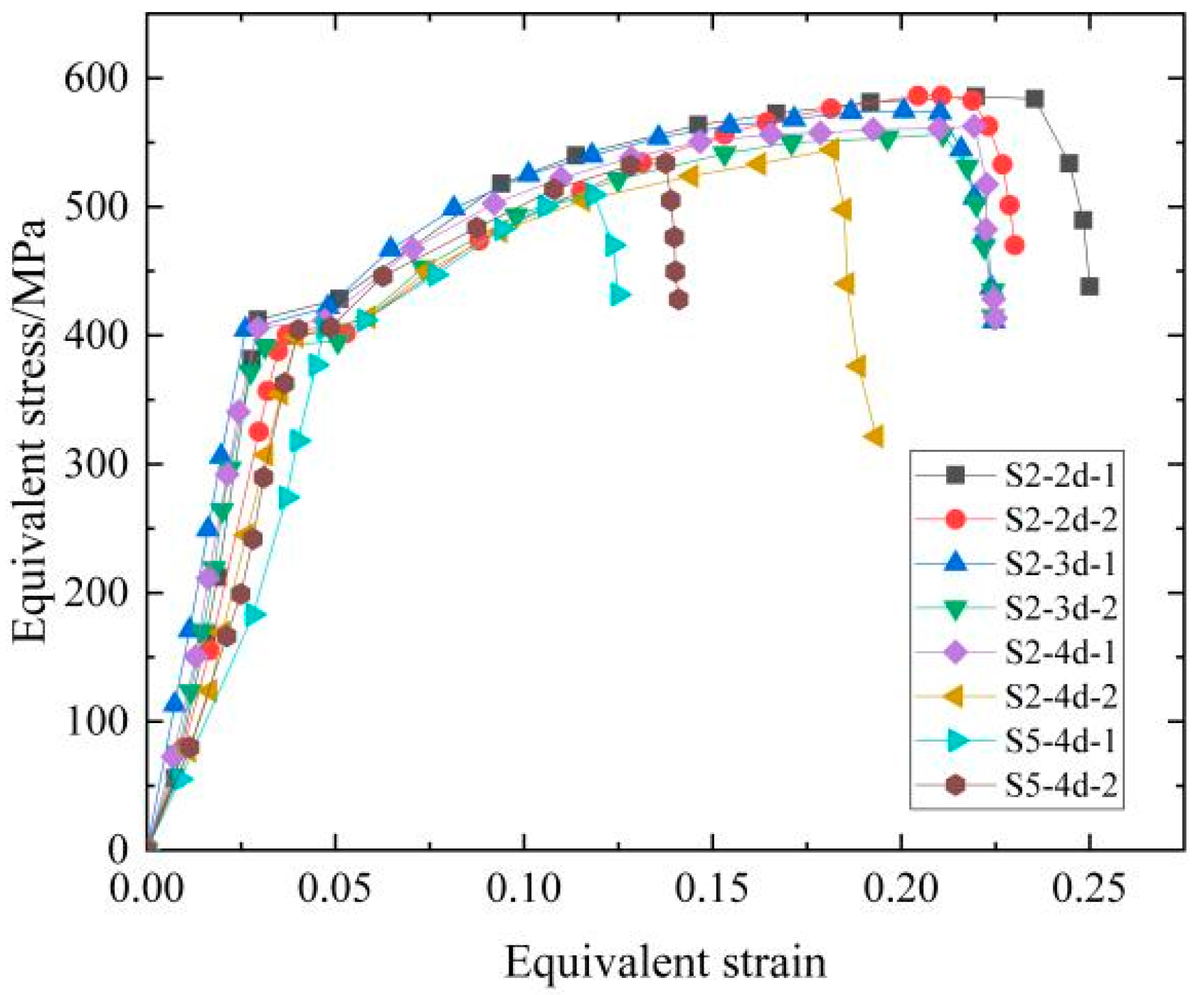
Guo [24] conducted uniaxial tensile tests on different types of sleeve grouting defective connectors and obtained the stress-strain curve of the sleeve grouting defective connector (S2 is the end defects, S5 is the anchor length defects) as shown in Figure 1. The stress-strain curve increases linearly in the yield stage and decreases after reaching the ultimate strength stage.

Figure 1.
Stress–strain curve of sleeve grouting defective connector.
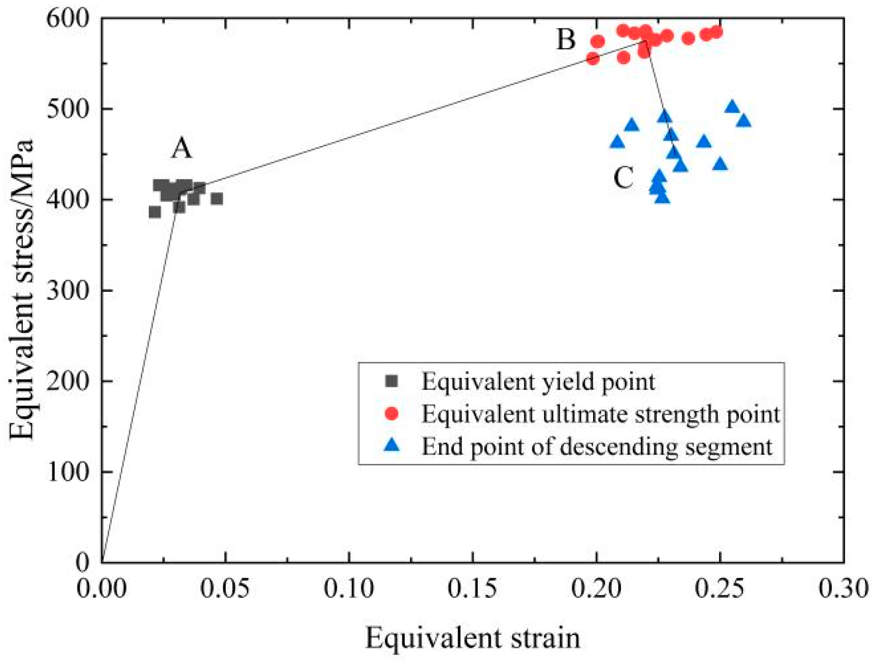
This paper constructed a constitutive model suitable for sleeve grouting defective connectors based on the existing test data. The model is a trilinear model with a descending section. The model is similar to the bilinear constitutive model of steel bars and is mainly to set a stress–strain descending section after the sleeve grouting connector reaches the ultimate strength. To better characterize the stress characteristics of the ‘trilinear’ of the sleeve grouting defect connector, Figure 2 summarizes the equivalent yield point, the equivalent ultimate strength point, and the end point of the descending section from the test results. Among them, point A and point B correspond to the equivalent yield point and the equivalent ultimate strength point of the sleeve grouting defect connectors, respectively, and point C is the end point of the descending section.

Figure 2.
Trilinear constitutive model of sleeve grouting defective connector.
The study investigated the influence of different types of defects, steel yield stress, and other factors on the constitutive model of sleeve grouting defect connectors using IBM’s statistical software SPSS (26.0). It was observed that the yield stress and ultimate stress of the sleeve grouting defect connector are strongly correlated with the yield strength of the steel bar. Therefore, the yield strength of the steel bar was chosen as the independent variable for regression analysis, and the fitting results were presented in Equations (1) and (2). The fitting coefficient R2 was used to judge the accuracy of formulas, whose values range from 0 to 1, and the closer to 1, the better the model fits. The calculation results showed that the R2 of Equations (1) and (2) were greater than 0.5, so the accuracy of the formulas was good. The strain and stress of endpoint C are mainly related to the type of sleeve grouting defects, and the value of this point can be determined according to the uniaxial tensile test of different types of sleeve grouting defect connectors.
where and are the stresses at points A and B, respectively, and is the yield strength of reinforcement.
2.2. Simplified Model of Sleeve Grouting Connector
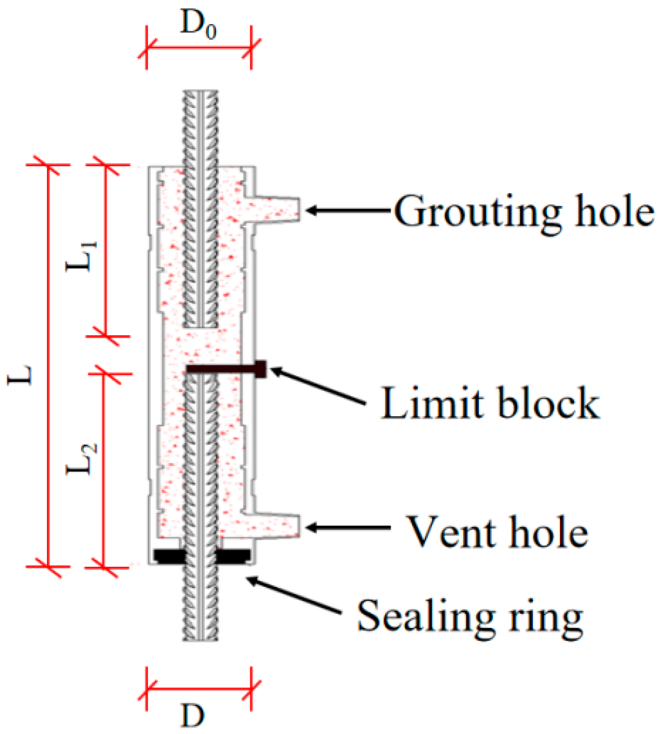
The full sleeve grouting connector structure is shown in Figure 3. The current finite element simulation methods for sleeve joints in prefabricated components are diverse, but the refined model of solid elements is still the main one. Although this method can simulate the connection performance of sleeve connectors well and, to some extent, reflect the difference in performance between sleeve connectors and steel bar connections, it still has problems such as complex computational models, low solving efficiency, and difficult convergence of the model. Therefore, it is necessary to simplify the sleeve connectors in the prefabricated components. At present, a few scholars [25,26,27] have utilized the equivalent substitution method to streamline the connectors in prefabricated buildings and have achieved relatively abundant results.
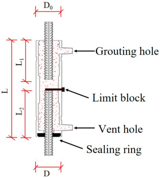
Figure 3.
Configuration of the fully-grouted sleeve connector.
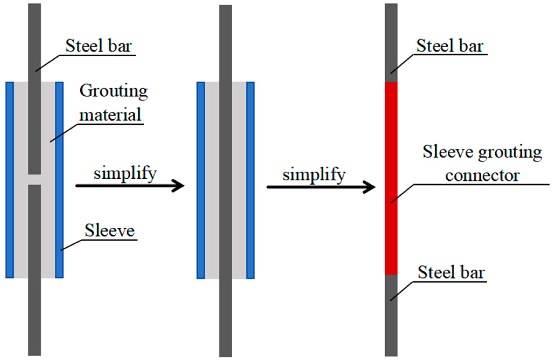
In this paper, due to the complexity of the full-sleeve grouting connector model and materials, the equivalent substitution method was also used to simplify the sleeve grouting connector in the prefabricated shear wall to facilitate model convergence. Specifically, it was simplified as a section of steel bar material, as shown in Figure 4. Among them, the red part represents the equivalent steel bar, which has the same diameter as the vertical steel bar but has a different stress-strain relationship. During the modeling process, the longitudinal steel bars connected by the sleeve grouting connector of the shear wall were divided, and the unit sets of steel bars and sleeve grouting connectors were established with corresponding material properties assigned to each.
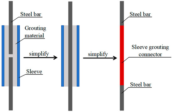
Figure 4.
Simplified model of sleeve grouting connector.
3. Finite Element Modeling of Prefabricated Shear Wall Considering Sleeve Grouting Defects
In this part, the finite element analysis model of prefabricated shear walls with sleeve grouting defects was established by finite element analysis software ABAQUS (2016), which was developed by Dassault Systèmesa company. And the modeling process was introduced in detail.
3.1. Element Type and Meshing
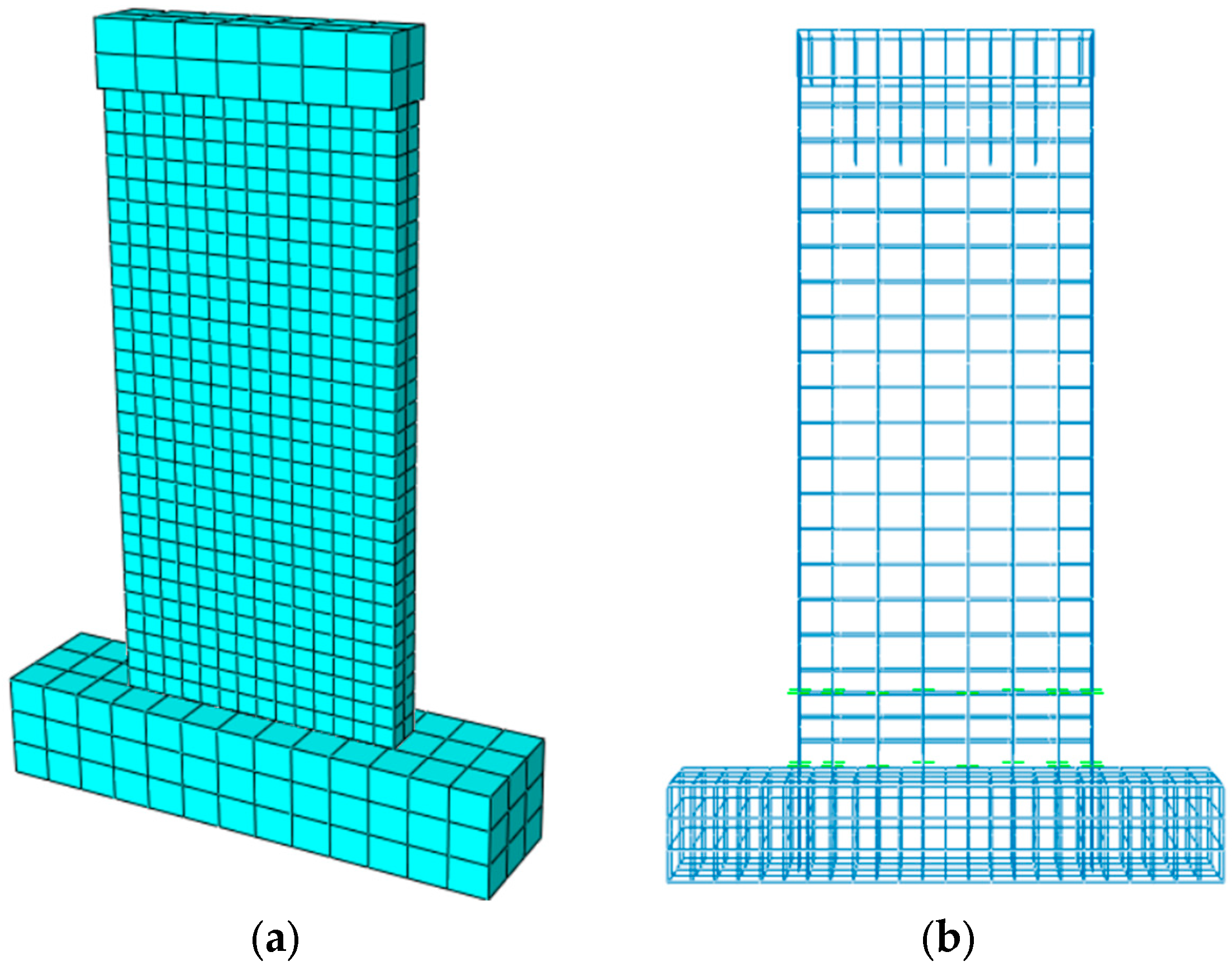
The modeling of prefabricated shear walls adopted the separation modeling method. In this model, the loading beam, shear wall, and other concrete components used the three-dimensional solid element (C3D8R), which is more accurate in calculating displacement and deformation and has a high grid utilization rate. In addition, the steel reinforcements and sleeve grout connectors use the 2-node linear 3-dimensional truss unit (T3D2), as shown in Figure 5. When meshing the model, it is necessary to consider the accuracy and calculation speed of the finite element simulation and select the appropriate meshing method. Figure 6 is the model and mesh division diagram of the specimen PW1 shear wall and steel bars.
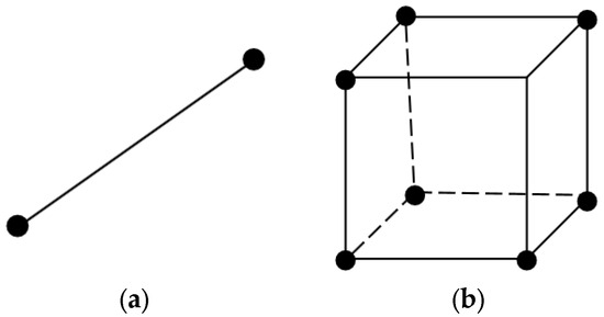
Figure 5.
Element type: (a) C3DR8 element; (b) T3D2 element.
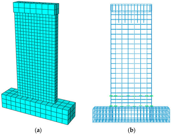
Figure 6.
Finite element model and mesh generation of specimen: (a) concrete; (b) reinforced steel skeleton.
3.2. Constitutive Model of Materials
3.2.1. Concrete
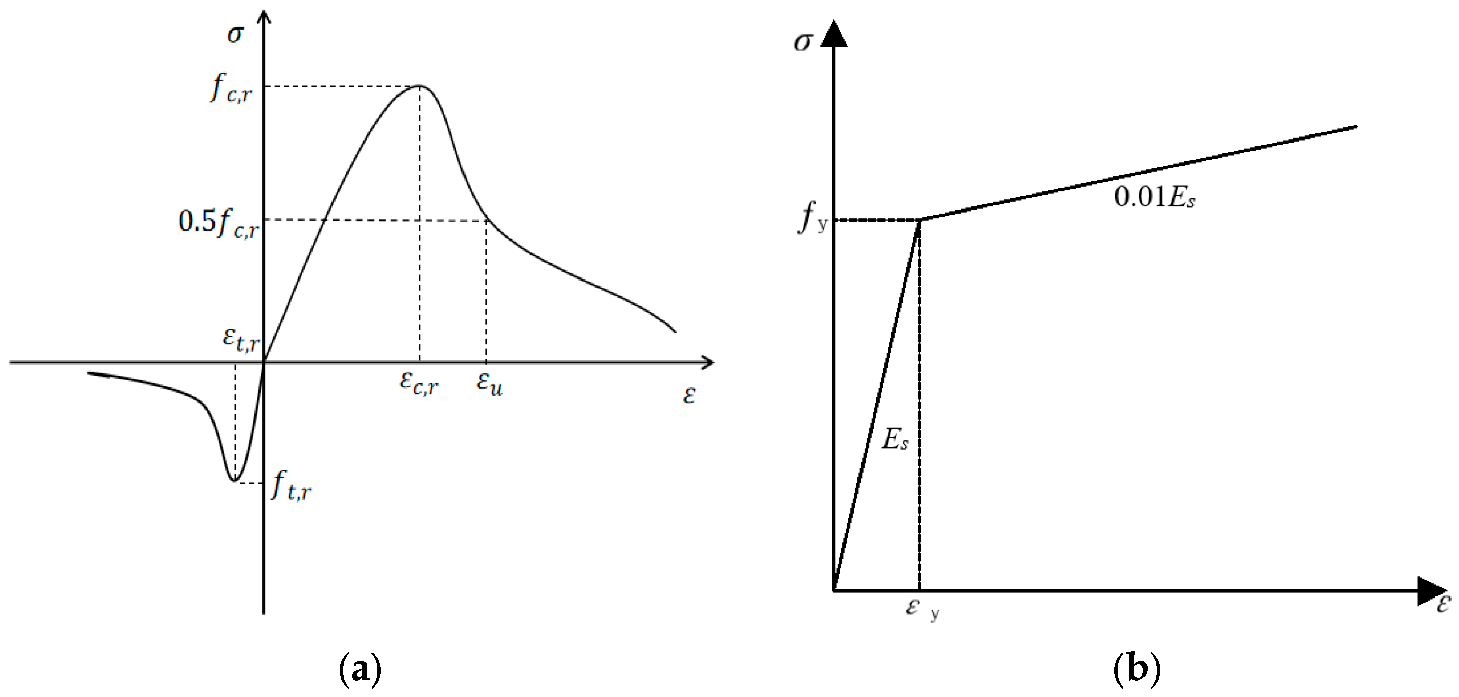
The constitutive model of concrete materials adopts a damage plasticity model that can effectively reflect the degradation of stiffness and strength of concrete during loading and the difference between tensile strength and compressive strength of concrete materials. Among them, the stress–strain relationship of concrete is determined according to the specification [28], as shown in Figure 7a.
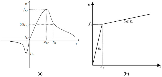
Figure 7.
Stress–strain curve: (a) concrete; (b) steel reinforcement.
The calculation formula of the uniaxial compression stress–strain curve of concrete is as follows:
where σ is the stress of concrete; ε is the strain of concrete; Ec is the elastic modulus of concrete; is the damage evolution parameter of concrete under uniaxial compression; , x, n are strength calculation parameters; is the parameter value of the descending section of the uniaxial compression stress-strain curve of concrete; is the representative value of the uniaxial compressive strength of concrete; is the peak compressive strain of concrete corresponding to the uniaxial compressive strength .
The calculation formula of the uniaxial tensile stress–strain curve of concrete is as follows:
where σ is the stress of concrete; ε is the strain of concrete; Ec is the elastic modulus of concrete; dt is the uniaxial tensile damage evolution parameter of concrete; and x are strength calculation parameters; is the parameter value of the descending section of the stress-strain curve of concrete under uniaxial tension; is the representative value of uniaxial tensile strength of concrete; is the peak tensile strain of concrete corresponding to the uniaxial tensile strength.
To accurately model the damage response of shear walls under horizontal cyclic loading, it is essential to establish compression and tension damage factors within the concrete plastic damage model. These factors were derived based on the Sidorov energy equivalence principle [29] with the following formula:
In order to simulate the damage behavior of shear walls under horizontal cyclic loading, it is necessary to define the compression and tension damage factors in the concrete plastic damage model. These factors were calculated according to the Sidoroff energy equivalence principle [29] with the formula as follows:
The elastic residual energy () of nondestructive materials is calculated as follows:
The elastic residual energy () of the damaged material is calculated as follows:
where is the initial elastic modulus; is the elastic modulus of the damaged material; is the effective stress of concrete, calculated according to the following formula:
Through simultaneous Equations (12)~(14), we can obtain the following:
According to the constitutive formula given by the specification [25], the expression of the damage factor can be obtained as follows:
where is the effective stress of concrete; is the initial elastic modulus; is the elastic modulus of the damaged material; D is the concrete damage factor; and dc/t is the damage parameter given in the specification.
The other five plastic parameters in the CDP model of ABAQUS Library are as follows: dilation angle φ and eccentricity e control the shape of the uncorrelated flow potential function G; the ratio of biaxial compressive strength to uniaxial compressive strength fc0/fc0 and constant stress ratio Kc control the yield surface of concrete; and the viscosity parameter λ is a viscoplastic regularization parameter used to improve model convergence difficulties due to material softening and stiffness degradation. Among them, e, fc0/fc0, and Kc were valued according to the ABAQUS user manual. However, the manual did not give the values of dilation angle φ and viscosity parameter λ, which can be determined by referring to the existing numerical simulation research and numerical analysis experience. Among these five parameters, only the expansion angle is dimensional, and the parameters’ specific values are shown in Table 1.

Table 1.
The other five plastic parameters of CDP.
3.2.2. Steel Reinforcement
The constitutive model of the steel reinforcement adopted the bilinear elastic–plastic model. Figure 7b shows the stress–strain (σ–ε) relationship of steel reinforcement. In the figure, the elastic modulus ES of reinforcement is 2 × 10⁵ Mpa, the tangent modulus after yield is Et = 0.01Es [30], and the Poisson’s ratio is 0.3.
3.3. Simulation of Horizontal Seaming
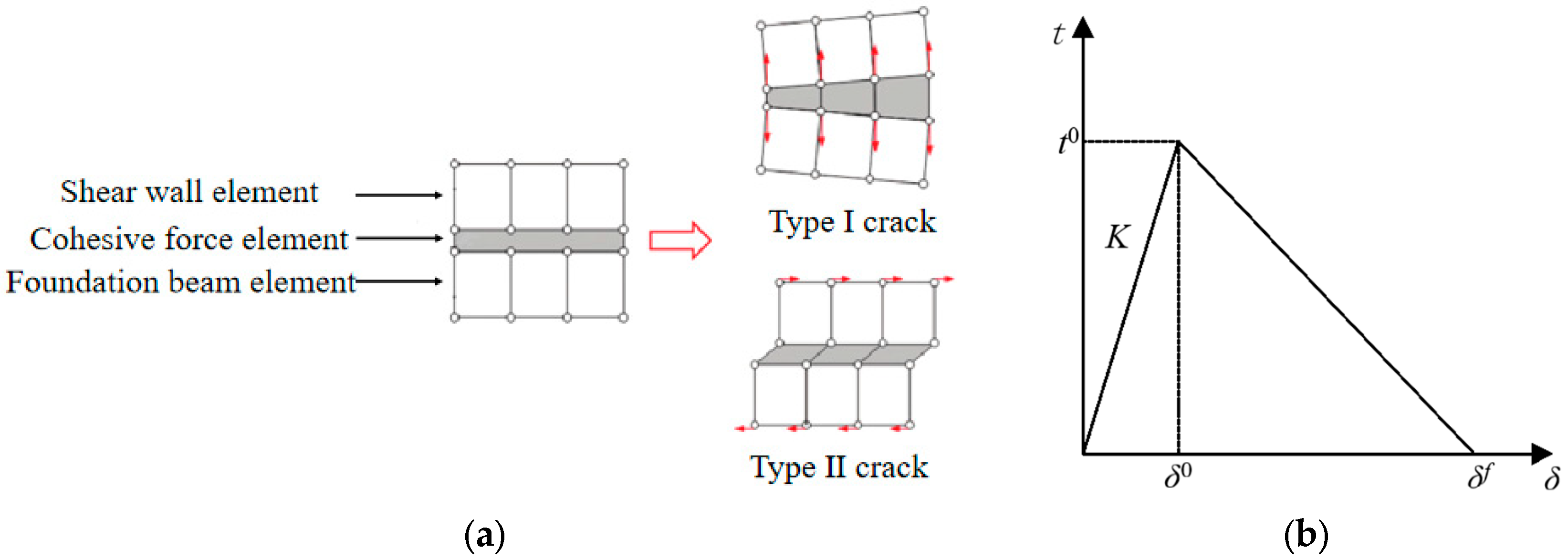
In the tests, the precast shear wall and the foundation beam were bonded by a 20 mm thick grouting material. During the finite element simulation, the mechanical properties of the horizontal joint between the shear wall and the foundation beam were simulated by the tangential shear stress-slip constitutive relationship and the normal bond constitutive relationship, that is, the Coulomb friction model and the cohesion model [31]. Among them, the Coulomb friction model mainly simulated the friction contact between the shear wall and the foundation beam, but it cannot simulate the interfacial bond slip between the shear wall and the foundation beam and the interfacial bond capacity in the damage stage. Besides, the cohesive element model regards the interface between the shear wall and the foundation beam as a large-scale broken ligament. The nonlinear fracture mechanics method was used to analyze the interface separation process, and the related mechanical properties, such as bonding, sliding, peeling, and fracture between the interfaces, can be simulated, as shown in Figure 8a.
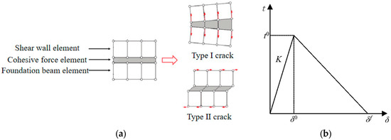
Figure 8.
Cohesion model: (a) cohesive element schematic diagram; (b) cohesive constitutive model.
In the Coulomb friction model, the normal behavior was defined as hard contact, the tangential behavior as a penalty function, and the friction coefficient is 0.6 in Reference [32]. Meanwhile, the cohesive constitutive model adopts a bilinear model, as shown in Figure 8b, which includes the linear stage and damage evolution stage.
The linear stage was represented by an elastic constitutive matrix, as shown in Equation (17). To facilitate the calculation, the tangential sliding effect of the joints was neglected, and the coupling of normal and tangential behavior was not considered. The stiffness coefficients Knn, Kss, and Ktt were set to the same value [31]. According to Reference [33], the interface stiffness is in the range of 5–13.5 MPa/mm.
where is the interface normal stress; and are the interface tangential stress; is the interface normal displacement; and are the interface normal displacement; is the normal stiffness coefficient; and are the tangential stiffness coefficients; , , and are the coupling stiffness coefficients.
When the interface stress reached the damage criterion, it entered the damage stage. The maximum stress criterion was adopted to determine the damage starting point, and the formula is as follows:
where is the normal stress of the interface; and are the tangential stress of the interface; are the maximum stress values corresponding to the elastic stage of the interface state, which corresponds to the normal peak stress and the tangential peak stress , and are calculated according to the formula in reference [34].
In the damage evolution stage, the damage evolution form adopted the linear evolution form, and the damage degradation law of the interface was controlled by defining the damage factor D. The formula is as follows:
where is the effective relative displacement at the time of failure; is the largest effective relative displacement in the loading process; is the peak effective relative displacement, and according to the literature [35], / value is 3.
3.4. Boundary Conditions and Loads
The loading beam and shear wall were connected by tie constraints, which bound the two regions in the model and made no relative displacement between them. The steel reinforcements and sleeve grouting connectors were embedded into the shear wall solid elements, and it was considered that the bond-slip did not occur between the steel bar and sleeve grouting connector and the concrete. The bottom of the foundation beam adopted fixed constraints. The load was coupled by setting a reference point at the centroid position of the top surface of the loading beam, and the vertical load was applied at the reference point. After keeping the vertical load unchanged, the horizontal displacement load was loaded according to the loading method of the test. The loading and constraints of the model are shown in Figure 9.
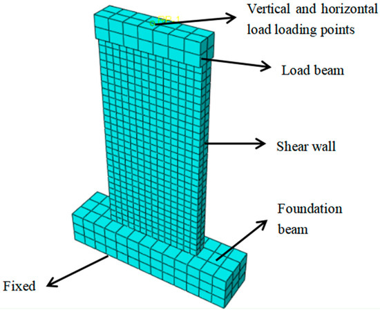
Figure 9.
Constraints and loading of shear wall finite element model.
4. Comparison and Verification of Simplified Methods for Prefabricated Shear Wall Considering Sleeve Grouting Defects
4.1. Verification Test Overview
The accuracy of the finite element modeling method is verified by establishing four different types of precast shear wall models with sleeve grouting defects in the existing experiments [21,22] and analyzing their seismic performance. Among them, PSW2 and PSW4 are test 1, and PW1 and PW4 are test 2, both using cyclic loading. The size of the specimens and the form of steel bars are shown in Table 2 and Figure 10.
Table 2.
Main parameters of specimens.

Figure 10.
Shear wall specimens and reinforcement diagram (Unit: mm): (a) test 1; (b) test 2.
According to the results of the material tests, the compressive strength of concrete in test 1 and test 2 was 30.95 MPa and 64.5 MPa, respectively. The material properties of steel bars and sleeve grouting connectors are in Table 3.
Table 3.
Test results of material properties.
4.2. Comparison and Verification of Numerical Simulation Results
4.2.1. Hysteretic Curve
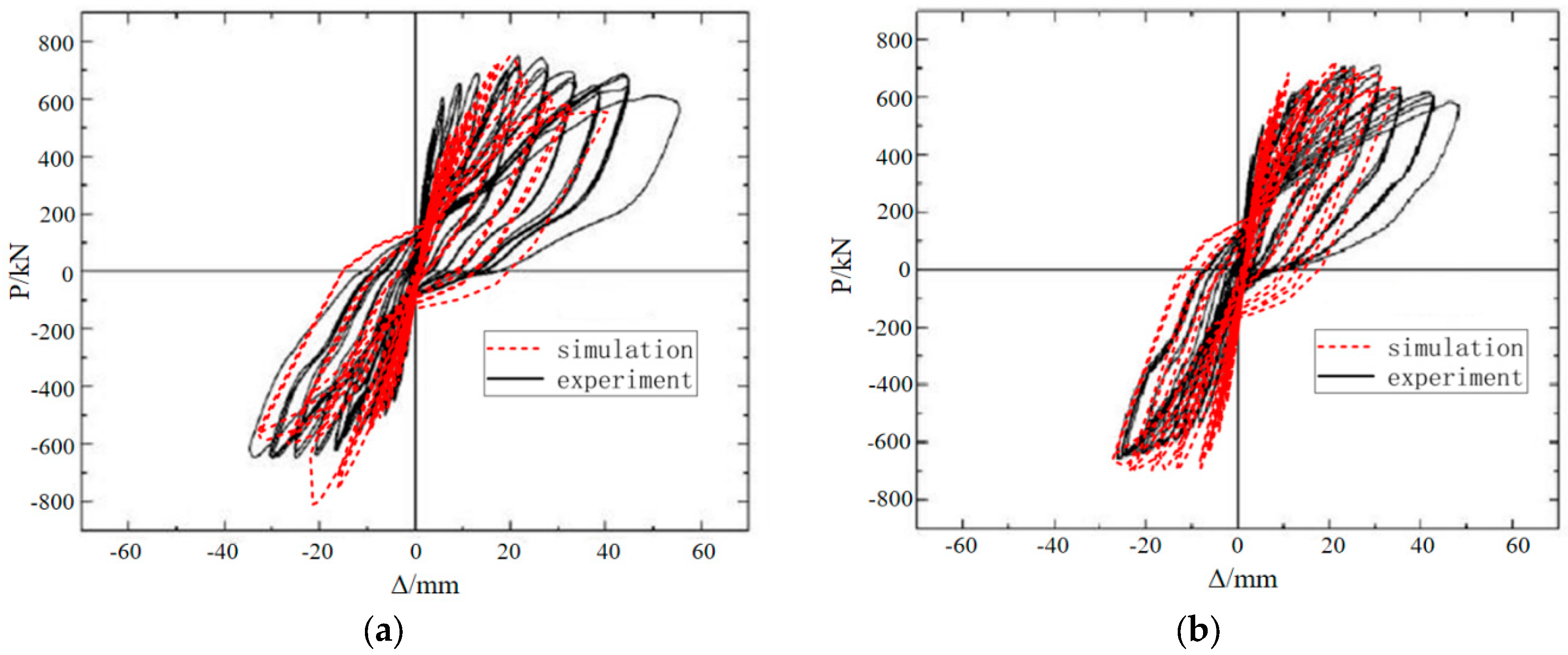
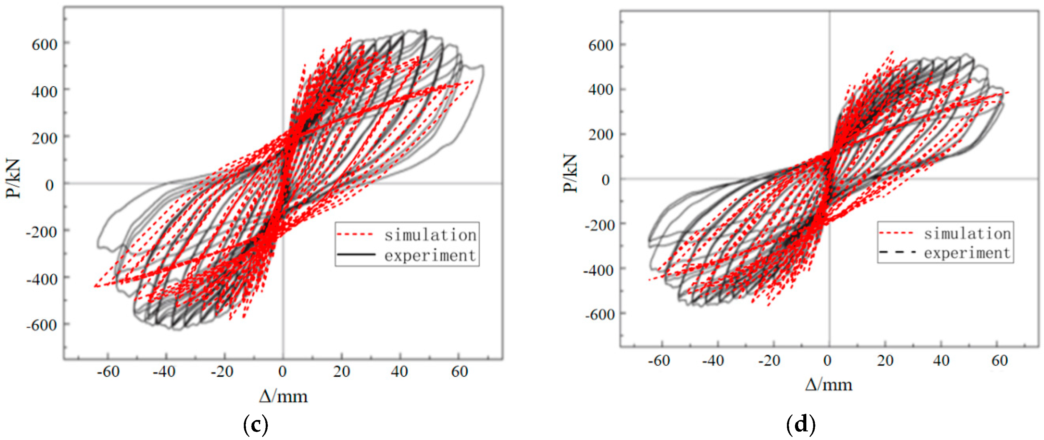
Figure 11 shows the comparison between the numerical simulation hysteresis curve and the test hysteresis curve of the prefabricated shear wall under horizontal cyclic loading. It can be seen from the figure that the simulation results are consistent with the test results in terms of initial stiffness and specimen-bearing capacity, and the hysteresis curve is relatively complete. However, there are some differences in the clamping effect on the hysteresis curve. With the increase of horizontal reciprocating load, the plastic damage of concrete accumulates continuously, which leads to a decrease in concrete stiffness. Compared with the test curve, the descending section of the numerical simulation curve is steeper, and the unloading stiffness is less than the actual unloading stiffness, which has a certain error with the test results. Besides, due to the influence of the test equipment on the reverse loading of PSW2 and PSW4 specimens, the reverse loading of the specimens can only reach 650 kN, which makes the peak bearing capacity of the reverse loading very different from the numerical simulation results.
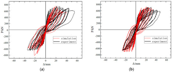

Figure 11.
Comparison of hysteresis curves between experimental results and simplified finite element model predictions: (a) PSW2; (b) PSW4; (c) PW1; (d) PW4.
4.2.2. Skeleton Curve
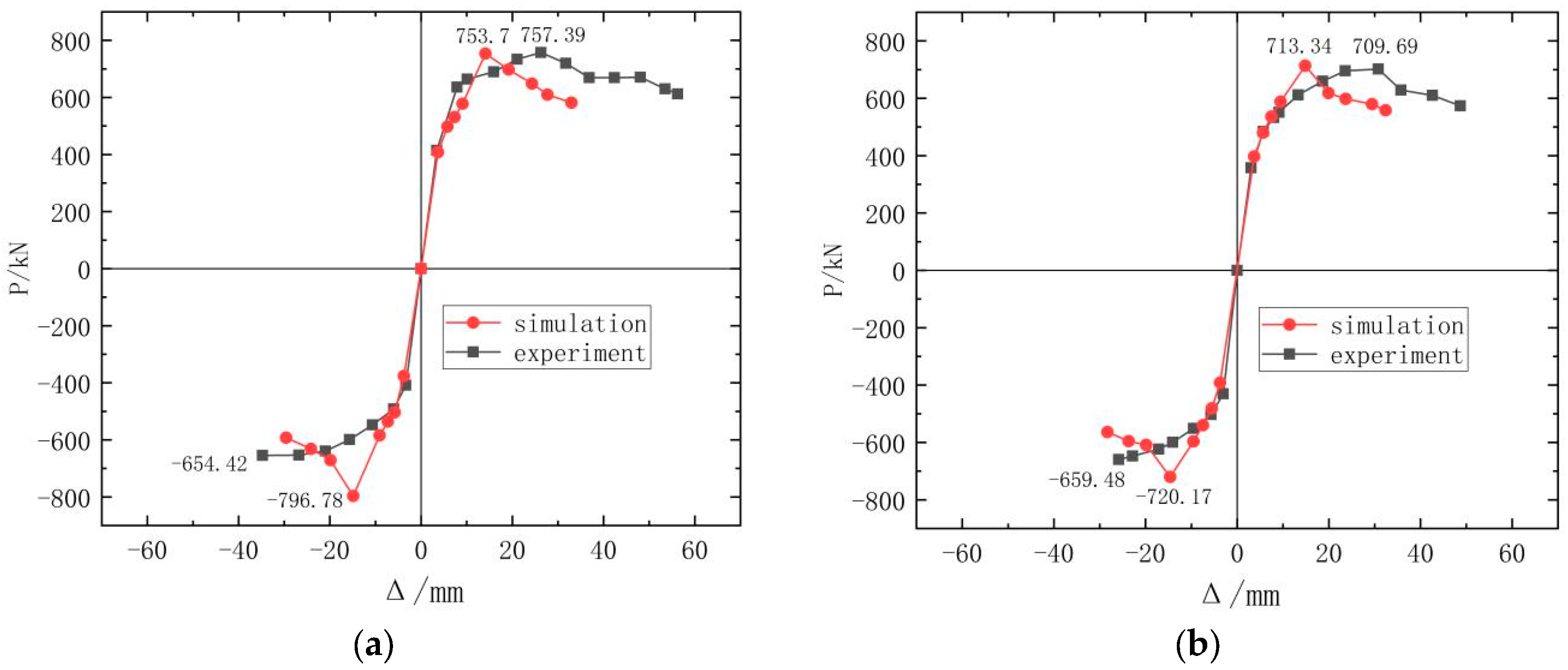
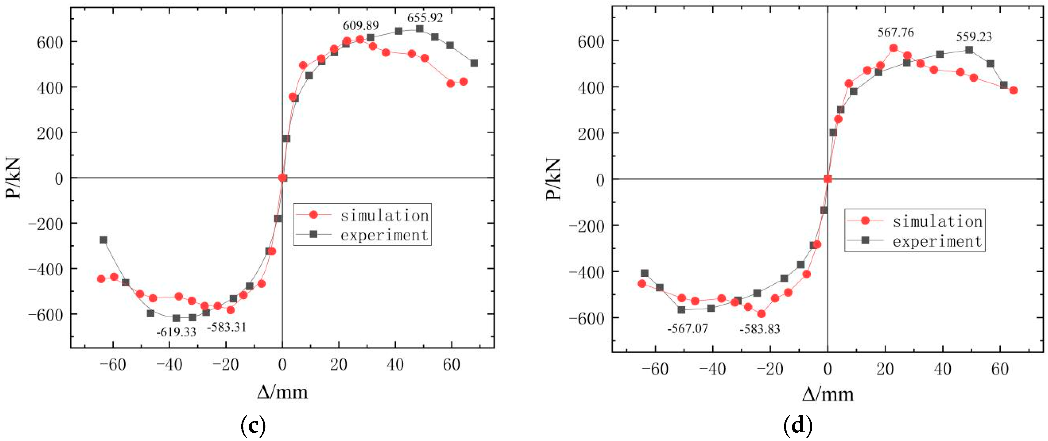
Figure 12 shows the comparison between the finite element simulation skeleton curve and the test skeleton curve of the prefabricated shear wall under horizontal cyclic load. Table 4 shows the comparison of bearing capacity and displacement of prefabricated shear walls under horizontal cyclic load. It can be seen from the diagram that the analysis results of the finite element model using the simplified modeling method under horizontal reciprocating load are close to the test results, and the average errors of peak bearing capacity and ultimate bearing capacity are 6.4% and 11.7%, respectively. However, the specimens PSW2 and PSW4 can only be loaded to 650 kN under the influence of the test equipment during the reverse loading, which makes the peak bearing capacity obtained by the test significantly different from that obtained by the finite element analysis.

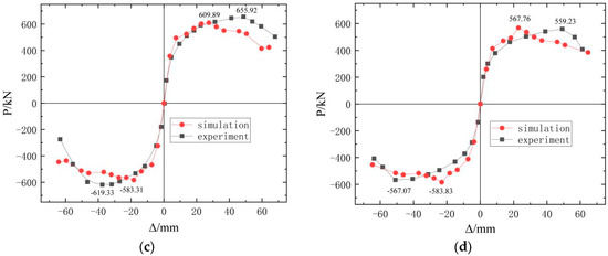
Figure 12.
Comparison of skeleton curve between experimental results and simplified finite element model predictions: (a) PSW2; (b) PSW4; (c) PW1; (d) PW4.
Table 4.
The comparison of bearing capacity and displacement of prefabricated shear walls.
In addition, the peak displacement obtained by the simulation is quite different from the test due to the high initial stiffness of the load. At the same time, with the continuous increase of horizontal reciprocating load, the plastic damage of concrete accumulates continuously, resulting in the degradation of concrete stiffness so that the descending section of the simulated curve is steeper than the test curve, and the unloading stiffness is less than the actual stiffness.
4.2.3. Failure Mode
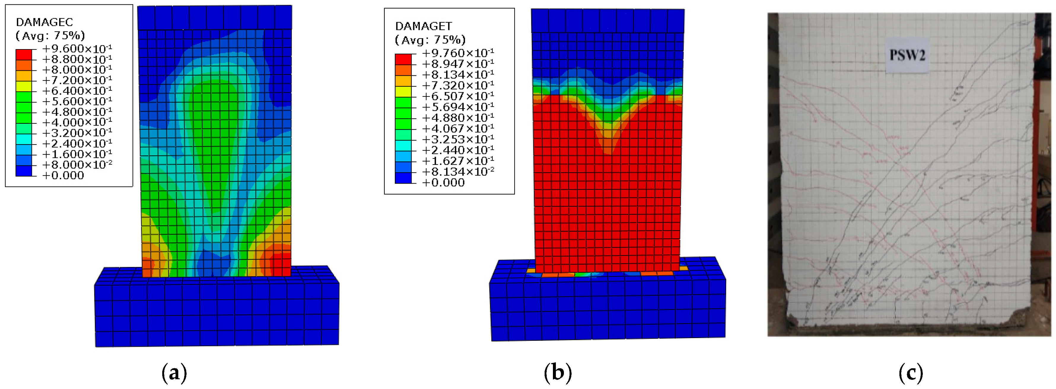
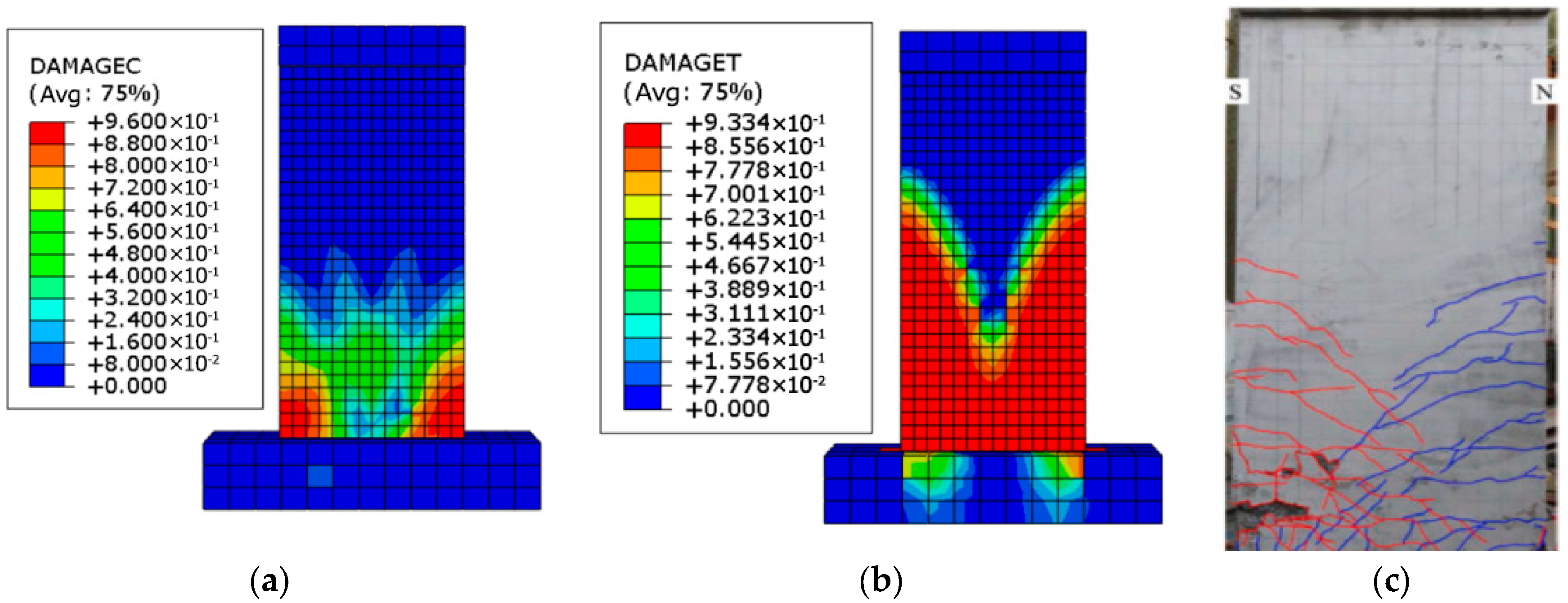
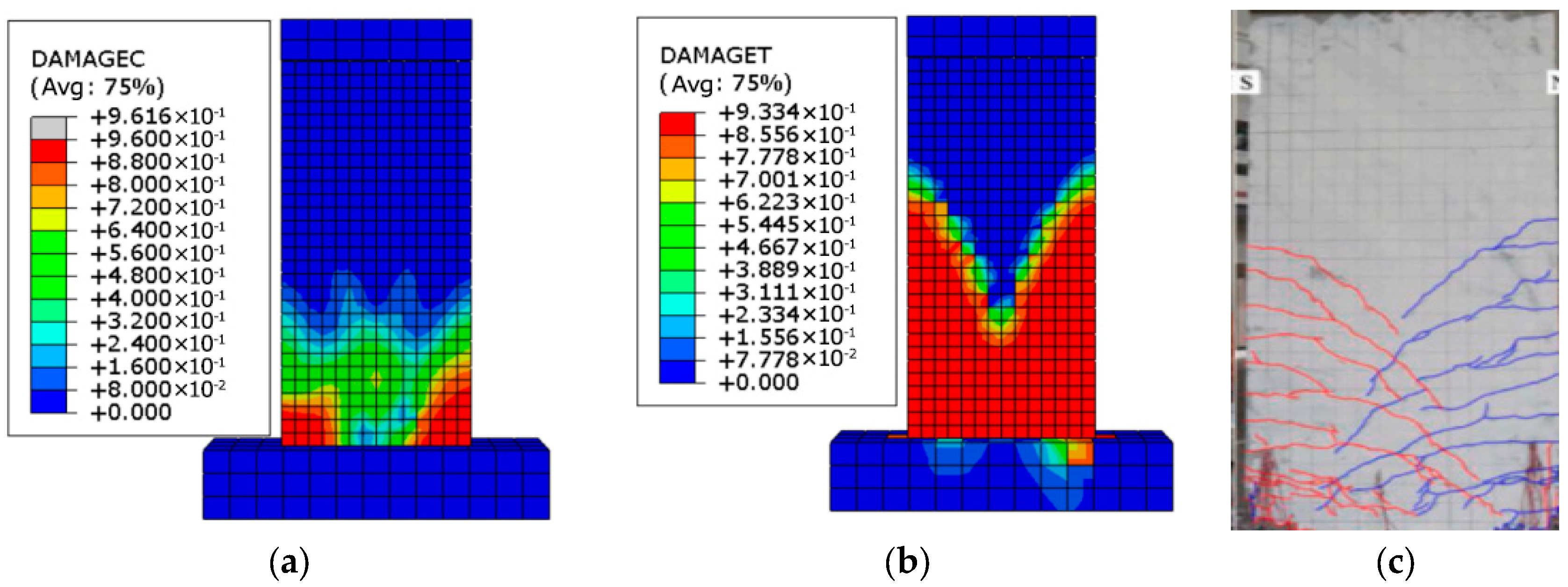
Figure 13, Figure 14, Figure 15 and Figure 16 show the compression and tensile damage distribution of the specimens and compare them with the actual failure mode results. It can be seen that the compression damage of sleeve grouting prefabricated shear walls was mainly concentrated at the bottom of the wall. Because the sleeve grouting defects were set on the right side of the wall, the compression damage value and compression damage areas on the right side of the wall were larger than those on the left side. The PSW2 and PSW4 were mainly flexural-shear cracking and had cross-inclined cracks parallel to the two diagonals. The failure modes of PSW 2 and PSW 4 were a flexural shear failure. The PW1 and PW4 were dominated by bending cracks, and the oblique cracks are mainly concentrated in the middle third of the walls, forming ‘X’ -shaped cracks in the bottom area of the walls. It shows that these walls show good bending performance. During the tests, due to the influence of the test equipment on the reverse loading of PSW2 and PSW4, the reverse loading of the specimens can only reach 650 kN, which makes the cracks on the left side of the wall more symmetrical than those on the right side and the right side was seriously damaged by tensile force. This is different from the numerical simulation results.

Figure 13.
Failure mode of PSW2 specimen: (a) compression damage; (b) tensile damage; (c) actual damage in the test.
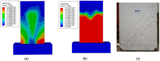
Figure 14.
Failure mode of PSW4 specimen: (a) compression damage; (b) tensile damage; (c) actual damage in the test.
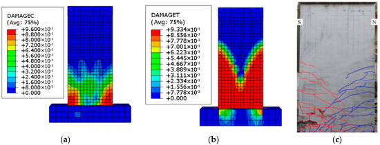
Figure 15.
Failure mode of PW1 specimen: (a) compression damage; (b) tensile damage; (c) actual damage in the test.
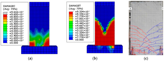
Figure 16.
Failure mode of PW4 specimen: (a) compression damage; (b) tensile damage; (c) actual damage in the test.
By comparing the results of the test and the Finite Element Analysis (FEA), it can be seen that the simplified modeling method based on the trilinear constitutive model of sleeve grouting defects can effectively simulate the seismic performance of prefabricated shear walls with sleeve grouting defects. Therefore, more performance analysis of prefabricated shear walls with sleeve grouting defects can be carried out on this basis.
5. Conclusions
This paper has proposed a simplified modeling method for prefabricated shear walls with sleeve grouting defects. By using the three-dimensional truss element T3D2, the sleeve grouting connector is simplified into a section of material with the same diameter as the vertical steel reinforcements and given the equivalent constitutive relation constructed based on the uniaxial tensile test of the sleeve grouting defective connection to achieve the simplification. In order to verify the reliability of this modeling method, four different types of sleeve grouting defect prefabricated shear walls are taken as examples to compare and analyze their seismic performance. The principal conclusions can be summarized as follows:
- (1)
- The finite element model modeling method of sleeve grouting connection prefabricated shear wall for different defects proposed in this paper can better simulate the seismic performance of shear walls, such as yield-bearing capacity, peak bearing capacity, and failure mode. It can also better reflect the ‘pinching’ characteristics of the hysteresis curve. However, it is important to note that the unloading stiffness is lower than the actual stiffness due to the continuous accumulation of plastic damage in concrete under horizontal cyclic loading;
- (2)
- In this paper, the trilinear constitutive model suitable for sleeve grouting defect connectors is constructed by classifying and analyzing the existing test data. It is related to sleeve end defect and anchorage length defect without considering other defects, which can be investigated in future studies;
- (3)
- The proposed modeling method can reduce the number of meshes and reduce the complexity of the model by simplifying the solid element into the truss element, which can provide a method for subsequent research on the performance of prefabricated shear walls with sleeve grouting defects and provide a reference for the performance evaluation and design optimization of the structure.
Author Contributions
Conceptualization, Y.W.; methodology, F.W.; numerical simulation, data curation and result analysis, F.W.; writing—original draft preparation, H.W.; writing—review and editing, Y.W. and H.W. All authors have read and agreed to the published version of the manuscript.
Funding
This research received no external funding.
Data Availability Statement
Data are contained within the article.
Conflicts of Interest
The authors declare no conflicts of interest.
References
- Cao, X.; Li, X.; Zhu, Y.; Zhang, Z. A comparative study of environmental performance between prefabricated and traditional residential buildings in China. J. Clean. Prod. 2015, 109, 131–143. [Google Scholar] [CrossRef]
- Hayashi, Y.; Shimizu, R.; Nakatsuka, T.; Suzuki, K. 2044 Bond stress-slip characteristic of reinforcing bar in grout-filled coupling steel sleeve. Proc. Jpn. Concr. Inst. 1993, 15, 271–276. [Google Scholar]
- Einea, A.; Yamane, T.; Tadros, M.K. Grout-filled pipe splices for precast concrete construction. J. PCI 1995, 40, 82–93. [Google Scholar] [CrossRef]
- Koushfar, K.; Rahman, A.B.A.; Ahmad, Y. Bond behavior of the reinforcement bar in glass fiber-reinforced polymer connector. J. Croat. Assoc. Civ. Eng. 2014, 66, 301–310. [Google Scholar]
- Ling, J.H.; Rahman, A.B.A.; Ibrahim, I.S. Feasibility study of grouted splice connector under tensile load. Constr. Build. Mater. 2014, 50, 530–539. [Google Scholar] [CrossRef]
- Ling, J.H.; Rahman, A.B.A.; Ibrahim, I.S.; Hamid, Z.A. Behaviour of grouted pipe splice under incremental tensile load. Constr. Build. Mater. 2012, 33, 90–98. [Google Scholar] [CrossRef]
- Zhang, P.; Yu, J.; Pang, Y.; Fan, J.; Guo, H.; Pan, Z. Experimental study on the mechanical properties of grouted sleeve joint with the fiber-reinforced grouting material. J. Build. Eng. 2021, 41, 102691. [Google Scholar] [CrossRef]
- Liu, C.; Pan, L.; Liu, H.; Tong, H.; Yang, Y.; Chen, W. Experimental and numerical investigation on mechanical properties of grouted-sleeve splices. Constr. Build. Mater. 2020, 260, 120441. [Google Scholar] [CrossRef]
- Ling, J.H.; Rahman, A.B.; Ibrahim, I.S.; Abdul Hamid, Z. An experimental study of welded bar sleeve wall panel connection under tensile, shear, and flexural loads. Int. J. Concr. Struct. Mater. 2017, 11, 525–540. [Google Scholar] [CrossRef]
- Du, X.; Wu, M.; Liu, H. The seismic performance of precast short-leg shear wall under cyclic loading. Adv. Struct. Eng. 2021, 24, 570–582. [Google Scholar] [CrossRef]
- Wu, M.; Liu, X.; Liu, H.; Du, X. Seismic performance of precast short-leg shear wall using a grouting sleeve connection. Eng. Struct. 2020, 208, 110338. [Google Scholar] [CrossRef]
- Lu, Z.; Wang, Y.; Li, J.; Fan, Q. Experimental study on seismic performance of L-shaped partly precast reinforced concrete shear wall with cast-in-situ boundary elements. Struct. Des. Tall. Spec. 2019, 28, e1602. [Google Scholar] [CrossRef]
- Li, J.; Wang, L.; Lu, Z.; Wang, Y. Experimental study of L-shaped precast RC shear walls with middle cast-in-situ joint. Struct. Des. Tall Spec. Build. 2018, 27, e1457. [Google Scholar] [CrossRef]
- Peng, Y.; Qian, J.; Wang, Y. Cyclic performance of precast concrete shear walls with a mortar–sleeve connection for longitudinal steel bars. Mater. Struct. 2016, 49, 2455–2469. [Google Scholar] [CrossRef]
- Peng, Y.; Wang, Y.; Qian, J. Mechanical behavior of precast building concrete walls with different connection technologies for seismic areas. Struct. Concr. 2020, 21, 1999–2010. [Google Scholar]
- Xue, L.; Sun, Q.; Ren, X. Numerical simulation of prefabricated shear wall based on cohesive element model. Earthq. Eng. Eng. Vib. 2020, 40, 174–182. [Google Scholar]
- Xu, F.; Wang, K.; Wang, S.; Li, W.; Liu, W.; Du, D. Experimental bond behavior of deformed rebars in half-grouted sleeve connections with insufficient grouting defect. Constr. Build. Mater. 2018, 185, 264–274. [Google Scholar] [CrossRef]
- Guo, H.; Zhang, J.; Wang, C. Experimental study on influence of connection defects on joint strength of half-grouted sleeve splicing of rebar. Adv. Civ. Eng. 2020, 2020, 5389861. [Google Scholar] [CrossRef]
- Espoir, K.K.; Xie, Z.; Desmond-Luke, M.A. Numerical study on the influence of defects in grouting on the mechanical properties of a full grouted sleeve connector. J. Adhes. 2022, 98, 2550–2581. [Google Scholar]
- Zheng, G.; Kuang, Z.; Xiao, J.; Pan, Z. Mechanical performance for defective and repaired grouted sleeve connections under uniaxial and cyclic loadings. Constr. Build. Mater. 2020, 233, 117233. [Google Scholar] [CrossRef]
- Xiao, S.; Wang, Z.; Li, X.; Harries, K.A.; Xu, Q.; Gao, R. Study of effects of sleeve grouting defects on the seismic performance of precast concrete shear walls. Eng. Struct. 2020, 236, 111833. [Google Scholar] [CrossRef]
- Yang, J.; Guo, T.; Wang, W.; Zhu, R. Experimental investigation on seismic behaviors of precast concrete shear walls with sleeve grouting defects. Adv. Struct. Eng. 2023, 26, 258–271. [Google Scholar] [CrossRef]
- Yan, H.; Song, B.; Xu, D.; Zhang, G. Seismic Performance of Assembled Shear Wall with Defective Sleeve Connection. CMES-Comp. Model. Eng. 2022, 131, 199–217. [Google Scholar] [CrossRef]
- Guo, T.; Yang, J.; Wang, W.; Li, C. Experimental investigation on connection performance of fully-grouted sleeve connectors with various grouting defects. Constr. Build. Mater. 2022, 327, 126981. [Google Scholar] [CrossRef]
- Xu, W.; Ma, B.; Huang, H.; Su, J.; Li, J.; Wang, R. The Seismic Performance of Precast Bridge Piers with Grouted Sleeves. Eng. Mech. 2020, 37, 93–104. [Google Scholar]
- Xue, L.; Sun, Q.; Ren, X.; Qin, X.; Xu, H. Reliability assessment of assembled shear wall structures considering stochastic defects in sleeve grouting. Earthq. Eng. Eng. Vib. 2024, 44, 14–24. [Google Scholar]
- Liu, H.; Yan, Q.; Du, X. Study of seismic performance of reinforced concrete frame beam-column joints connected withgrouted sleeves. Build. Struct. 2017, 18, 54–61. [Google Scholar]
- GB/T 50010-2010; Code for Design of Concrete Structures. China Architecture & Building Press: Beijing, China, 2011.
- Sidoroff, F. Description of anisotropic damage application to elasticity. In Physical Non-Linearities in Structural Analysis: Proceedings of the International Union of Theoretical and Applied Mechanics, Senlis, France, 27–30 May 1980; Springer: Berlin/Heidelberg, Germany, 1981; pp. 237–244. [Google Scholar]
- Peng, Y. Experimental Study on Seismic Behavior of Pre-Cast Reinforced Concrete Shear Walls. Master’s Thesis, Tsinghua University, Beijing, China, 2010. [Google Scholar]
- Dang, X.; Lyu, X.; Qian, J.; Zhou, Y. Finite element simulation of self-centering pre-stressed shear walls with horizontal bottom slits. Eng. Mech. 2017, 34, 51–63. [Google Scholar]
- EN 1992-1-1; Eurocode 2: Design of Concrete Structures-Part 1-1: General Rules and Rules for Buildings. British Standard Institution: London, UK, 2004.
- Liu, P. Study on Behaviors of Hinge Joints for Fabricated Reinforced Concrete Simply-Supported Plate Girder Bridges. Master’s Thesis, Tsinghua University, Beijing, China, 2010. [Google Scholar]
- Wang, L.; Lin, Y.; Qian, Y. Experimental Research on Shear Properties of New-to-Old Concrete Interface. J. Southwest Jiaotong Univ. 2005, 5, 600–604. [Google Scholar]
- Wu, Y.; Chen, W. Cohesive zone model based analysis of bond strength between FRP and concrete. Eng. Mech. 2010, 27, 113–119. [Google Scholar]


Disclaimer/Publisher’s Note: The statements, opinions and data contained in all publications are solely those of the individual author(s) and contributor(s) and not of MDPI and/or the editor(s). MDPI and/or the editor(s) disclaim responsibility for any injury to people or property resulting from any ideas, methods, instructions or products referred to in the content. |
© 2024 by the authors. Licensee MDPI, Basel, Switzerland. This article is an open access article distributed under the terms and conditions of the Creative Commons Attribution (CC BY) license (https://creativecommons.org/licenses/by/4.0/).