Article

Study on Seismic Performance of RC Frame Structures Considering the Effect of Infilled Walls

by
Xuetan Zhang
1,2,
Yang Zhou
1,2,3,4,*,
Xiangyu Liu
1,
Yaoyu Zheng
1 and
Zhengxin Qi
5
1
School of Civil Engineering, Institute of Disaster Prevention, Sanhe 065201, China
2
Key Laboratory of Building Collapse Mechanism and Disaster Prevention, China Earthquake Administration, Sanhe 065201, China
3
Hebei Technology Innovation Center for Multi-Hazard Resilience and Emergency Handling of Engineering Structures, Sanhe 065201, China
4
Langfang Key Laboratory of Anti-Seismic Collapse of Engineering Structures, Sanhe 065201, China
5
China Nuclear Industry 24 Construction Co., Ltd., Sanhe 065201, China
*
Author to whom correspondence should be addressed.
Buildings 2024, 14(7), 1907; https://doi.org/10.3390/buildings14071907
Submission received: 27 May 2024 / Revised: 16 June 2024 / Accepted: 20 June 2024 / Published: 22 June 2024
(This article belongs to the Section Building Structures)

Abstract

:
This paper studies the impact of half-height infilled walls on the failure modes of frame columns through quasi-static tests of both frame models and half-height infilled wall frame models. Based on the experimental results, a seismic analysis model of reinforced concrete (RC) frame structures is established, and parametric studies are carried out to analyze the effects of masonry materials and masonry heights on the seismic performance of structures. The results show that the load-bearing capacity and stiffness of the structure are improved, while the ductility of the structure is reduced because of the existence of infilled walls. As the height of infilled walls increases, there is a notable decrease in the free height of frame columns. At a wall-to-column height ratio of 0.2, the masonry walls exert a negligible effect on the frame structure’s seismic performance. In contrast, at a ratio of 0.6, there is a transition in column failure modes from bending to shearing. When evaluated at consistent masonry heights, aerated concrete block-infilled walls demonstrate the least impact on the seismic performance of RC frame structures. Thus, in the absence of additional structural enhancements, the use of aerated concrete blocks is recommended to mitigate the negative implications of infilled walls on the seismic integrity of RC frames.

1. Introduction

China is located at the junction of the Pacific Plate and the Eurasian Plate, where the earth’s crust is active and earthquakes are frequent, posing a serious threat to the safety of people’s lives and property. Multi-story RC frame structures are widely used in various countries worldwide due to their construction convenience, economic applicability, and other advantages [1]. However, the current seismic design code, when considering the effect of infilled walls on the seismic performance of frame structures, only provides a reduction calculation formula for the natural period. The interaction between the walls and the frame beam–column system isn’t fully discussed, and the mechanism of interaction needs to be perfected. In addition, infilled walls play different roles under various limit states, and their capacity to change the structure’s natural period as a function of inter-story displacement also varies [2]. Taking the Wenchuan earthquake as an example, seismic damage investigation findings revealed that the collapse index of multi-story RC frame structures within regions of extreme seismic activity exceeded even that of multi-story masonry constructions, which significantly differs from the traditional perspectives regarding the earthquake resilience of multi-story RC frame structures. Furthermore, the presence of infilled walls predisposes frame structures to more pronounced damage during seismic events compared to pure frame structures. Thus, the seismic performance of structures with infilled walls remains a stern challenge and a significant field of study [3,4,5,6,7,8].
Numerous scholars have conducted extensive research on frame-infilled wall structures. Al-Chaar et al. [9] conducted quasi-static tests on single-story planar frame models with different numbers of spans and concluded that the installation of infilled walls can enhance the ultimate strength and initial stiffness of the structure. Hashemi et al. [10] conducted a shake table experimental study on an RC frame structure with non-reinforced masonry-infilled walls. The results indicated that the presence of infilled walls significantly enhanced the structure’s stiffness by a factor of 3.8, albeit at the cost of reducing its ductility. Lin et al. [11] harnessed MSC.MARC software (version 2005) to study the impact of floors and walls on the seismic response of structures. They concluded that the reinforcing effect of floors on beams leads to “weak columns and strong beams” and that frames with irregularly placed infilled walls are prone to weak stories and may also result in torsional responses. Guo et al. [12] conducted three sets of quasi-static tests on single-story, two-span frame structures with irregularly arranged infilled walls. Their research revealed that the restraining effect of infilled walls on columns not only diminishes the columns’ ductility and energy dissipation capacity, but also changes the failure mode of the frame structure. Kakaletsis et al. [13], Tasnimi et al. [14], and Mansouri et al. [15] conducted experimental research on the seismic performance of frame structures with infilled walls featuring openings. The results showed that the presence of openings changed the failure mode of the frame structures and reduced the ductility, strength, and load-bearing capacity of the structures. Jin [16] and Yang [17] took the collapsed teaching building of Xuan Kou Middle School in the Wenchuan earthquake as a prototype and employed shake table tests and simulation methods to explore seismic failure mechanisms in frames with continuous half-height infilled walls under disparate seismic scenarios. They highlighted that near-window, half-height infills act as structural collapse catalysts. Zovkic et al. [18], Siddiqui et al. [19], and Dautaj et al. [20] carried out experimental research on RC frame specimens with infilled walls made of different materials. The results showed that the structural failure mode is related to the wall material. Frames with lower-strength materials mainly experienced shear failure of the masonry-infilled walls and bending failure of columns, while frames with higher-strength materials exhibited shear failure of both columns and infilled walls. Jiang et al. [21] and Zhou et al. [22,23] undertook quasi-static experimental studies to evaluate the seismic performance of infilled wall frames employing various connection methods. Their research concluded that adopting flexible connection schemes significantly enhances the seismic resilience of engineering structures. Teguh [24] and Baghi et al. [25] conducted quasi-static experimental studies on RC plane frames and found that infilled walls can significantly increase the load-bearing capacity of reinforced concrete frames and enhance their anti-collapse capability. Onat et al. [26] paid attention to the in-plane and out-of-plane effects of infilled walls. Through shake table tests, they demonstrated that the in-plane load-bearing capacity of reinforced infilled walls is greater than that of non-reinforced infilled walls, but the out-of-plane load-bearing capacities of the two specimens are quite similar. Guljaš et al. [27] conducted a shake table comparative experiment on a three-story RC frame with infilled walls. The results showed that properly arranged masonry-infilled walls can effectively control the inter-story displacement of structures, satisfying the ductility requirements of the structures. Binici et al. [28] demonstrated through experiments that aerated concrete infilled walls are prone to cracking at small deformations, and the gap between the frame beam and the infilled wall does not have a significant impact on the seismic performance of the structure. In addition, the development prospects of RC frame-infill wall structures are discussed in references [29,30].
At present, to enhance the seismic resistance of building structures, some scholars have conducted research on wall reinforcement. Almasabha and Chao [31] investigated a new detail for reinforcing rectangular reinforced concrete squat walls, which significantly improved the ductility and strength of the structural walls. Furthermore, with the advancement of socio-economic development and technological levels, the number of steel-structured buildings has increased dramatically. Chao et al. [32] investigated the performance and viability of horizontal stiffener detailing (HSD). The research shows that the HSD is a viable and economic alternative for shear links, which has the potential to decrease welding in the shear link while exhibiting adequate seismic performance.
Based on existing research findings, this paper primarily focuses on the impact of infilled walls on deformation patterns, force mechanisms, and failure modes of RC frame structures. Employing quasi-static examination and finite element analysis, it delves into the systematic impact exerted by masonry materials and the height of infilled walls on the earthquake resilience of RC frame edifices.

2. Materials and Methods

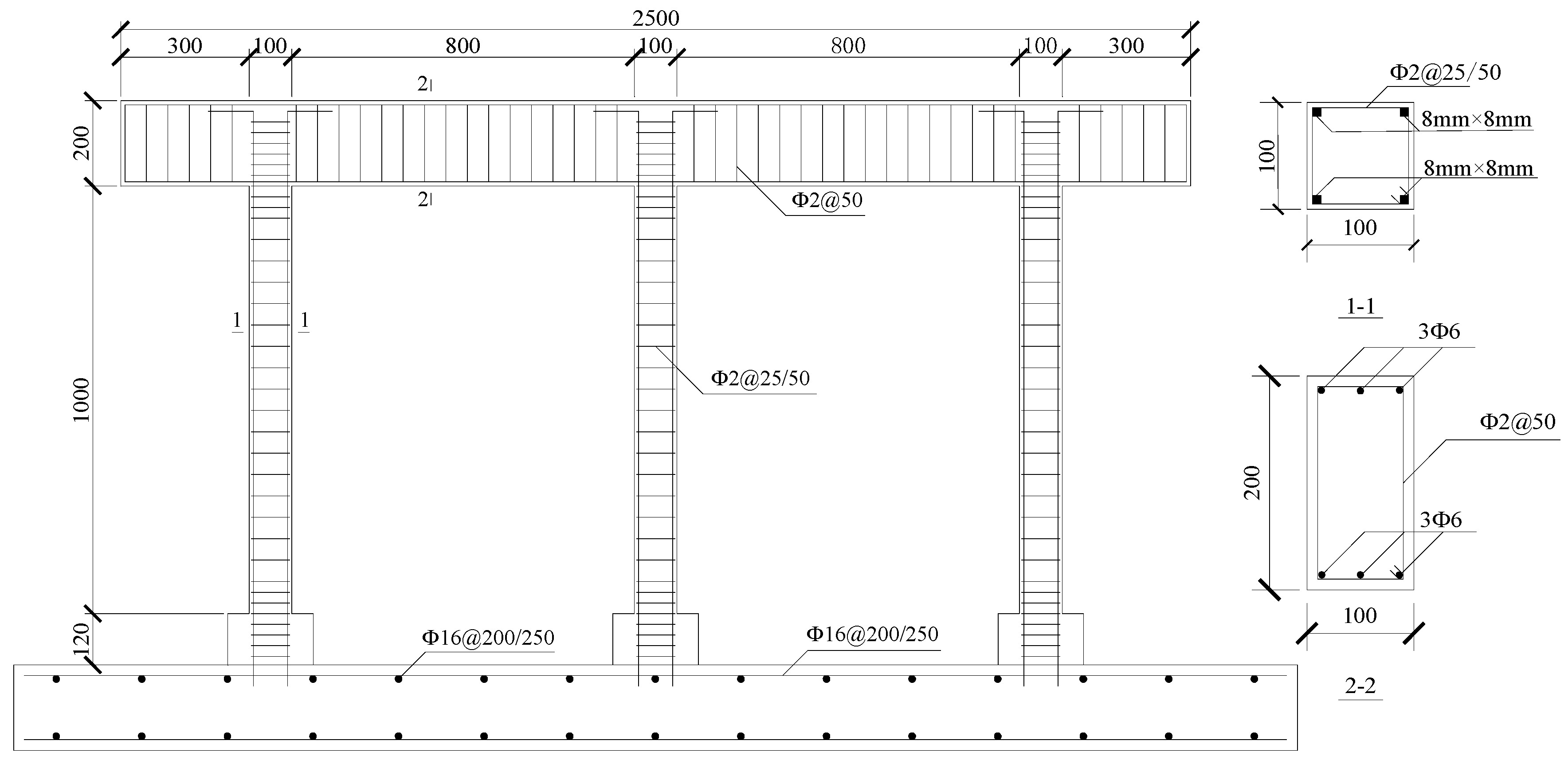
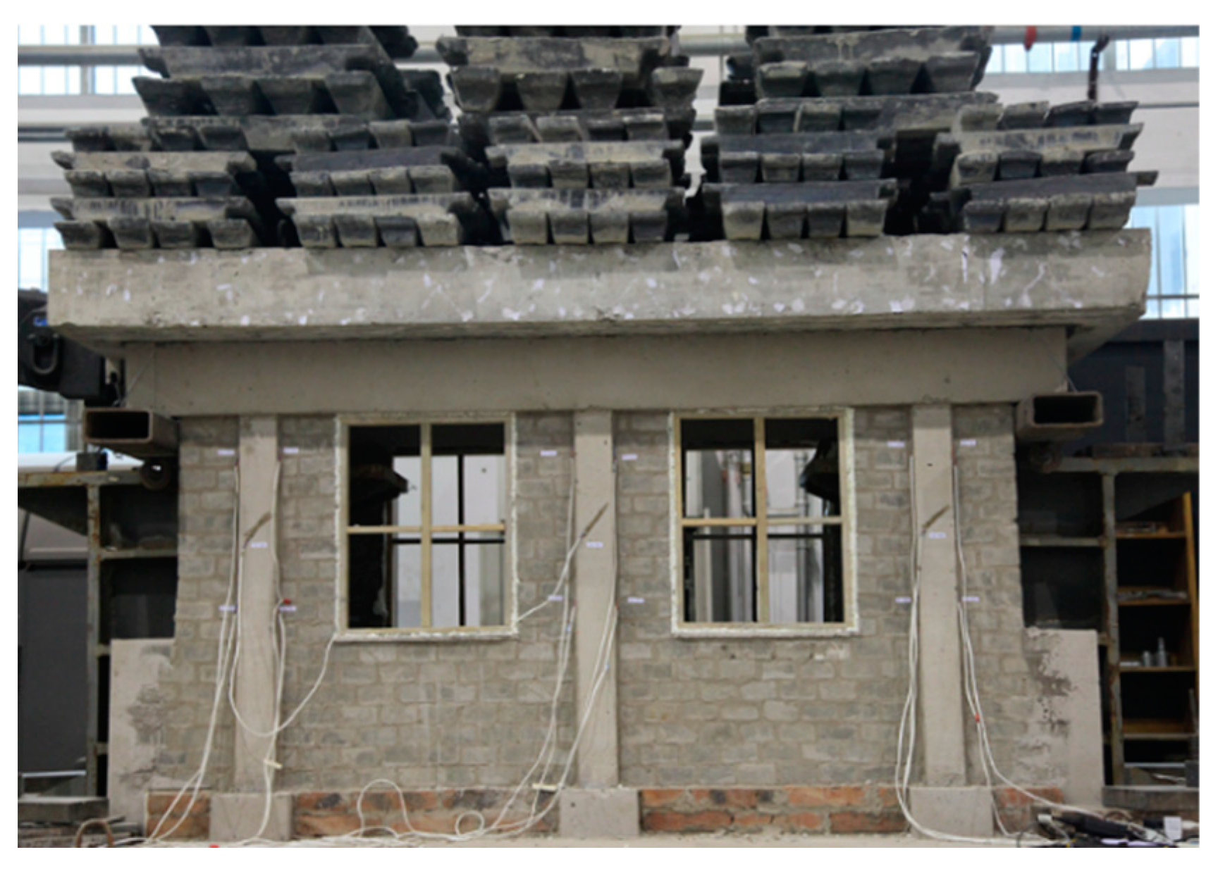
2.1. Design and Manufacturing of Test Model

In this test, two sets of two-bay, two-span, and single-story RC frame structure models are designed at a scale ratio of 1:4 following the specification for seismic testing of buildings (JGJ/T 101—2015) [33], including frames without walls and frames with half-height walls. The impact of half-height infilled walls on the seismic performance of RC frame structures is explored through quasi-static tests. The frame model without infilled walls is denoted as F, and the frame model with half-height infilled walls is denoted as FW.
For model F, three frame columns are set up as vertical load-bearing components and lateral force-bearing components for each bay of the frame, which are uniformly distributed along each longitudinal axis with a longitudinal spacing of 900 mm, a transverse spacing of 800 mm, a clear height of 1000 mm, and cross-section dimensions of 100 mm × 100 mm. A total of 4 pieces of rectangular mild steel with a side length of 8 mm are placed as the longitudinal reinforcement to form a protective layer with a thickness of 5 mm. The steel wires with a diameter of 2 mm are adopted as stirrups with a spacing of 50 mm to densify within 100 mm at the top and bottom of the column with a spacing of 25 mm. The frame beam is designed with a length of 2500 mm and cross-sectional dimensions of 100 mm × 200 mm. A total of 6 pieces of HRB335-grade steel rebars with a diameter of 6 mm are placed as the longitudinal reinforcement to form a protective layer with a thickness of 10 mm. The steel wires with a diameter of 2 mm are adopted as the stirrups with a spacing of 50 mm to densify within 100 mm of the beam–column joints with a spacing of 25 mm. In previous seismic quasi-static tests conducted, there was an occurrence of “lifting” at the base of the columns during the loading process, which led to distortion in the model results. Against this backdrop, the experimental model in this study has adopted an enlarged “column base” with dimensions of 150 mm × 150 mm and a height of 120 mm to enhance the connection between the column and the base plate. This enlargement of the column base is akin to the foundation in actual buildings, and it does not affect the seismic performance of the frame structure during the tests. The geometric dimensions of the two sets of models and the reinforcement configuration of the frame beams and columns are shown in Figure 1. It should be noted that the base of the experimental model is a prefabricated reinforced concrete base designed for multiple reuses, which means the longitudinal reinforcement cannot be connected to the base reinforcement directly. To address this, the experimental model employs a method of “drilling holes in the base plate for rebar insertion and sealing with epoxy resin” to connect the longitudinal reinforcement with the base plate.
Model FW is identical to model F in the column grid design, beam–column sectional dimensions, and reinforcement configuration. The infilled walls are constructed of hollow concrete blocks. To ensure integrity, tie bars of 2Φ2@150 mm are set along with the column height, extending 30 mm into the frame column and 160 mm into the wall. On the exterior of the outermost columns, a half-height wall is erected, complemented by concrete short columns of equivalent height, ensuring that the mechanical attributes and restraining capacity across the model’s six columns are essentially uniform. The models are shown in Figure 2 and Figure 3.

2.2. Experimental Material

All test model frames are constructed using fine-particle concrete, utilizing ordinary Portland cement with a strength of 42.5 MPa. The composition of the concrete involves a mass ratio mix of cement, sand, and stone at 1:2.6:4, with a water-to-cement ratio approximately set at 0.7. During the concrete pouring phase, three cubic concrete specimens, each measuring 150 mm × 150 mm × 150 mm, are cast for every frame model to ensure the consistency of concrete strength between the specimens and the frame model. They are cured for 28 days under the same conditions as the experimental model. On the day of each test, axial compression strength tests are conducted on the three sets of cubic concrete specimens corresponding to the model, and the average value is taken as the cubic compressive strength of the model. The infilled walls are constructed from small hollow blocks, each measuring 98 mm × 48 mm × 48 mm, with cement and sand mixed at a ratio of 1:5. The blocks and mortar used in the column base area are identical to those utilized in the remainder of the wall. The window frame is made of wood, with dimensions of 480 mm in width and 600 mm in height. Mild steel bars with an 8 mm side length serve as the longitudinal load-bearing reinforcement for the frame columns, while HRB335 ribbed steel bars, 6 mm in diameter, are employed for the longitudinal load-bearing reinforcement of the frame beams. Galvanized iron wires, 2 mm in diameter, are used as stirrups within the frame beams and columns. The material performance parameters utilized in the trial are documented in Table 1.

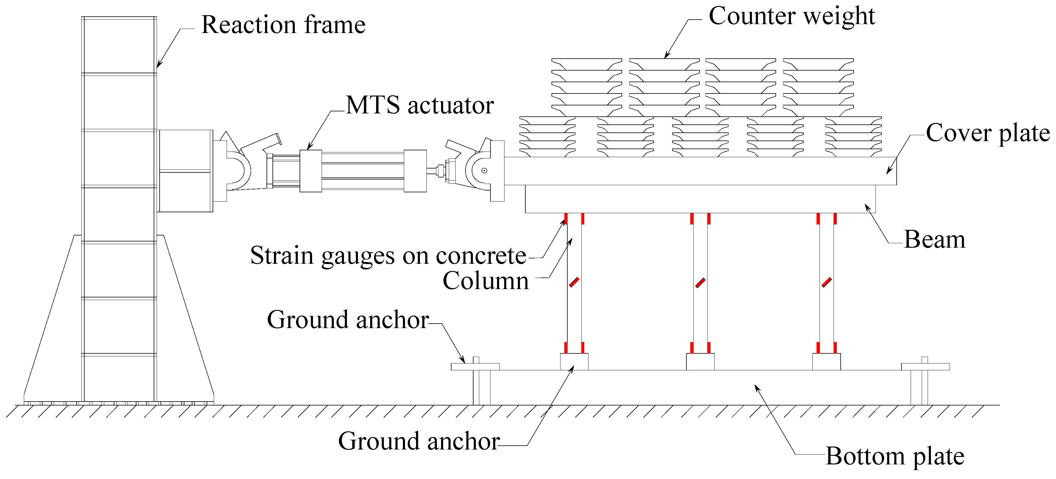
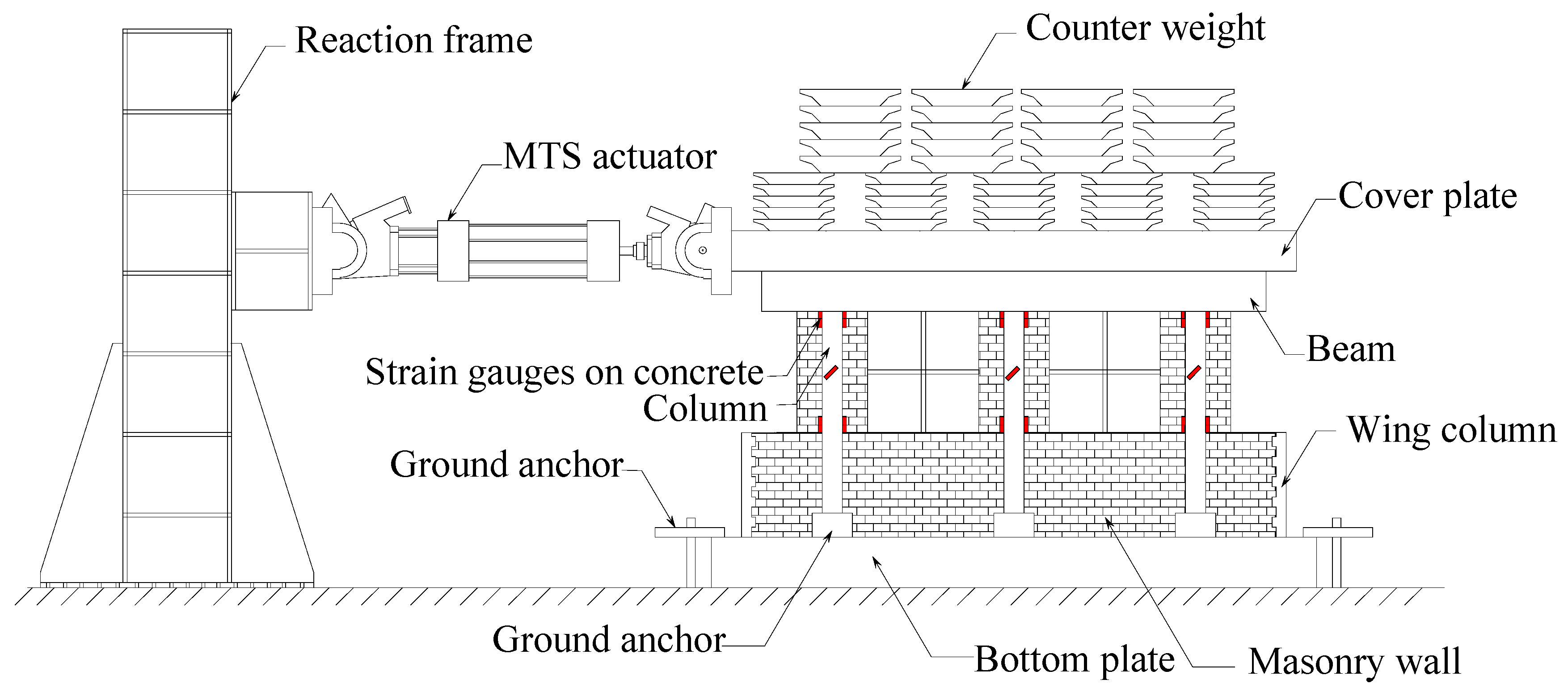
2.3. Experimental Equipment and Loading Scheme

For the experiments, the MTS hydraulic servo actuator (MTS (China) Co., Ltd., Shenzhen, China) is employed to exert horizontal cyclic loading onto the model by controlling displacement. Before testing, the actuator is anchored at one end to the I-shaped steel beam of the reaction frame and connected at the other end to reinforcing embedded parts on the reinforced concrete cover plate using bolts. The cover plate is centrally positioned atop two planar frame beams and is securely bonded with high-strength cement mortar. Counterweights are introduced to simulate the column’s axial compression ratio during the test loading phase, ensuring the same axial compression ratios for the columns. A counterweight of 13.85 t is assigned to Model F and 13.65 t to Model FW. Considering the capstone’s weight is 2 t, the axial compression ratio for the columns is ascertained to be 0.3. The physical metrics gauged throughout testing encompass force, displacement, and strain, with the actuator’s thrust and displacement being procured via the apparatus’s control system feedback. Strain gauges affixed to the concrete are utilized to measure the strain in the frame columns. The placement of the strain measurement points for all frame models can be observed in Figure 4 and Figure 5.
As referenced in [34], to guarantee the continuity and homogeneity of cyclic loading, small displacement amplitudes should be initially selected for cyclic loading, with increments in displacement restrained to not surpass 10% of the yield displacement before reaching it. The two test models employ displacement-controlled loading with analogous procedures, which can be divided into 15 levels of loading as follows: 0.2 mm, 0.4 mm, 0.8 mm, 1.2 mm, 2.0 mm, 3.0 mm, 4.0 mm, 6.0 mm, 8.0 mm, 12.0 mm, 16.0 mm, 20.0 mm, 24.0 mm, 28.0 mm, and 32.0 mm. Each level is reciprocally applied three times, as shown in Figure 6. The test is stopped when the bearing capacity of the frame model drops below 85% of the peak load or when further loading is implausible due to substantial damage.

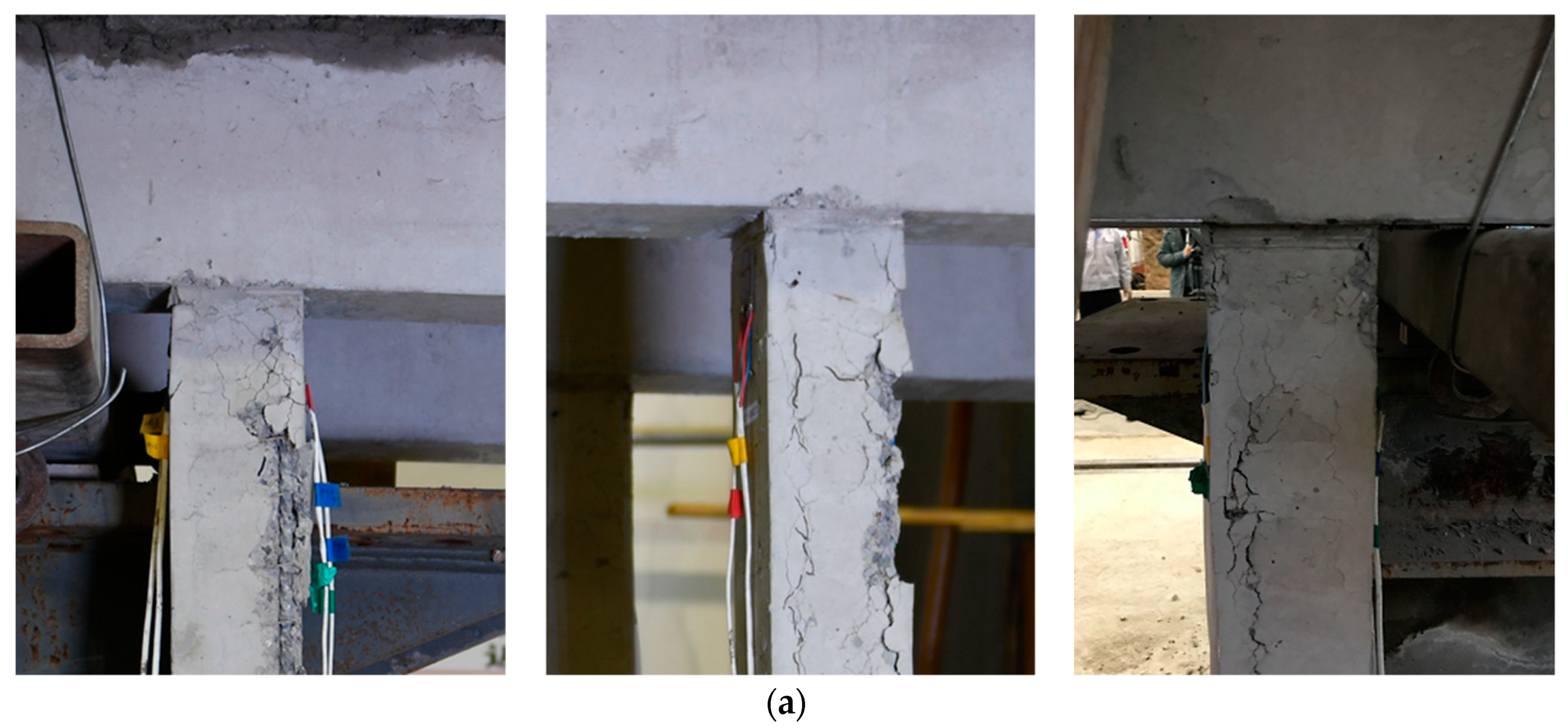
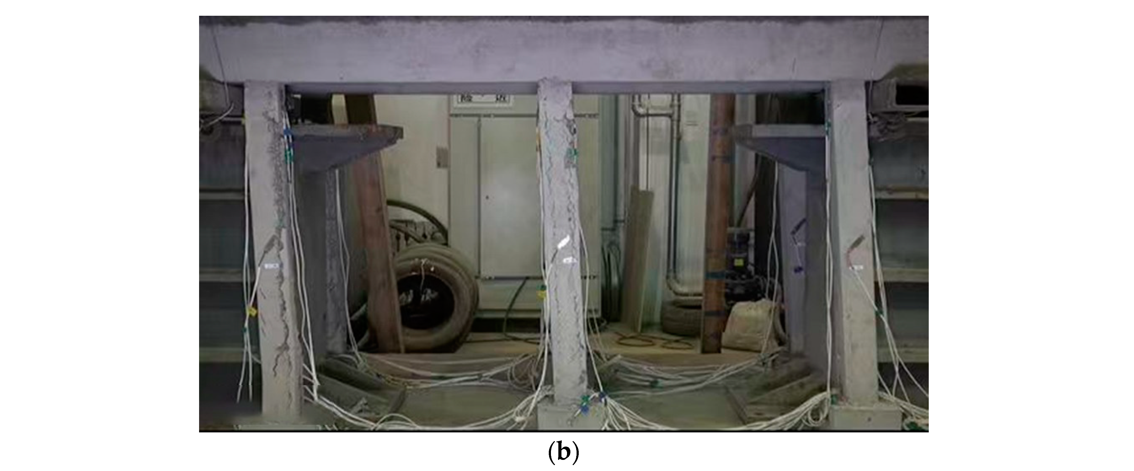
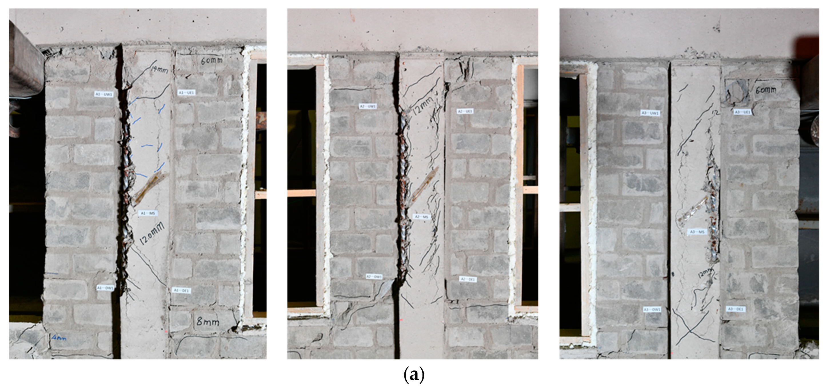
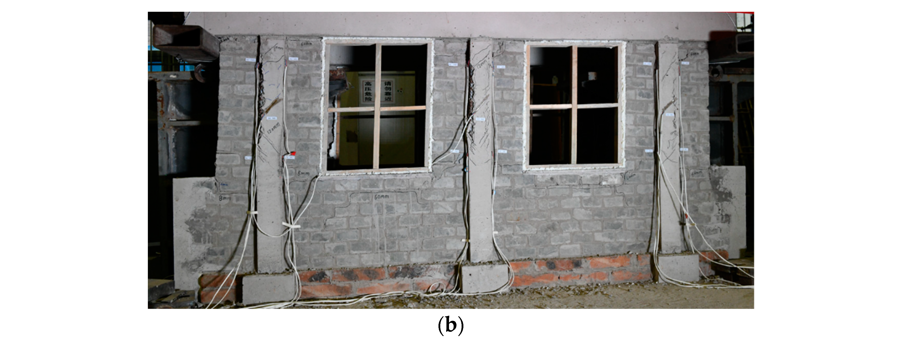
2.4. Experimental Phenomenon Analysis

In cases of small displacement in Model F, the concrete surface exhibits no signs of fissuring. Upon being subjected to a 6 mm load, the initial onset of horizontal cracking is observed at the column ends. As the amplitude of the applied displacement increases, cracks at both ends of the concrete columns continue to extend outward while also widening. Upon reaching a displacement of 20 mm, the column cracks propagate in a manner that aligns with the direction of the longitudinal reinforcement. Upon a 32 mm load being applied, a large section of concrete detaches from the ends of the frame columns, unveiling the internal longitudinal reinforcement and thereby inducing significant residual displacement. The respective failure conditions for the left edge column, middle column, and right edge column are depicted sequentially in Figure 7.
In Model FW, minor damage emerges in cases of modest displacement, attributable to the interaction between the infilled walls and the frame. Upon application of a 6 mm load, diagonal cracks materialize in the infilled walls beneath the window. At an increased load of 8 mm, the infilled walls’ fractures intensify rapidly, accompanied by the onset of horizontal displacement at the summit of the columns. As the displacement incrementally escalates, the frame columns exhibit diagonal cracks and longitudinal splintering. Upon a 20 mm load, the diagonal cracking at the column apex becomes conspicuous, and the intersection of the frame column and infilled walls incurs damage, inciting further extension of wall cracking. With a 32 mm load, evident longitudinal splitting cracks are discernible in the central column, which uncovers the internal longitudinal reinforcement. Concurrently, through-cracks form at the juncture of the infilled walls and frame columns. The progression of damage for the left edge column, central column, and right edge column is sequentially illustrated in Figure 8.

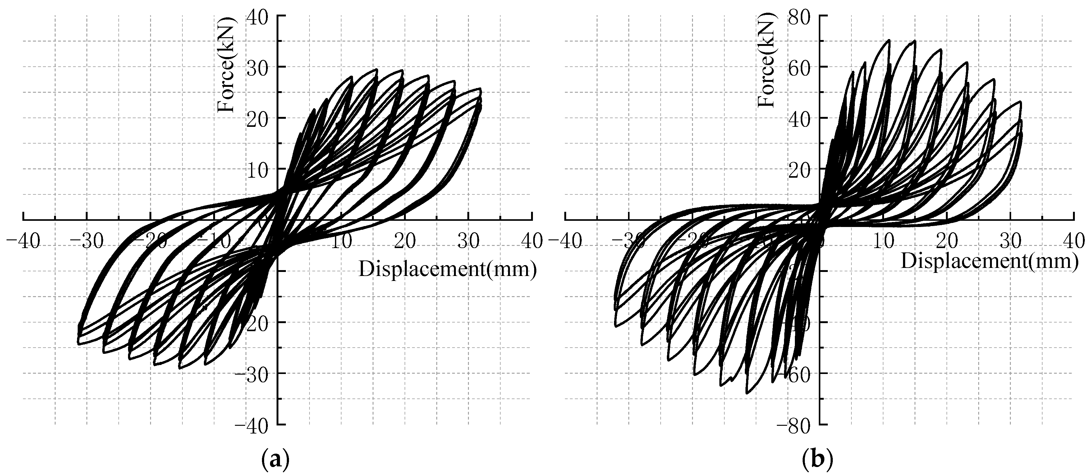
2.5. Experimental Results Analysis

The reciprocal loading effects on the model’s deformation capability, stiffness degradation, and energy dissipation are encapsulated within the hysteresis curve, as shown in Figure 9. Observational analysis reveals that the hysteresis loops for both sets of model configurations maintain commendable symmetry. Moreover, each iterative loading cycle in an identical direction results in a diminishing sloping gradient relative to its antecedent, indicating the stiffness degradation effect of the component under repeated loading in the same case. Comparatively examining the hysteresis loops’ morphology, Model F’s loop is fuller than that of Model FW, accompanying smaller variations in load-bearing capacity. However, Model FW surpasses Model F in terms of ultimate load-bearing capacity, coupled with a faster rate of capacity degradation. Additionally, due to issues with processing accuracy, there is also slippage between the actuator loading frame and the model, resulting in a significant pinching effect in the load–displacement hysteresis curve. This has a certain adverse effect on the study of the structure’s energy dissipation characteristics. However, it has a lesser impact on the trends of stiffness and bearing capacity changes, which focus on the peak information of structural force and displacement.
To more precisely discern the strength, stiffness, and ductility characteristics at each stage of the tested model, the load extremities of each level within the hysteresis curve are sequentially interconnected to form an envelope line. This envelope line consequently yielded the model’s skeleton curve, as shown in Figure 10. Derived from this skeleton curve, crucial parameters such as ultimate displacement, yield displacement, ultimate load, ductility coefficient, and initial stiffness for both sets of models can be ascertained and are enumerated in Table 2.
It is clear that the placement of half-height infilled walls significantly enhances the model’s ultimate load-bearing capacity and initial stiffness, while its deformability and ductility are diminished, as outlined in Table 1. The ultimate load-bearing capacity of Model FW, with the addition of walls, is approximately 2.38 times greater than that of Model F, and the initial stiffness is roughly 3.15 times higher. As shown in Figure 11, it is indicated that the rate of stiffness reduction for the frame FW with infilled walls far exceeds that of Model F. When the displacement is applied up to 6 mm, the rate of stiffness reduction for the frame structure with infilled walls is notably higher, after which the rate of reduction slows down. This suggests that upon reaching a 6 mm load, the infilled walls in Model FW have incurred severe fatigue, effectively compromising their lateral stiffness.
In conclusion, the arrangement of half-height infilled walls has successfully augmented the initial stiffness and load-bearing capacity of the RC frame structure. However, this enhancement has simultaneously led to a decrease in the structure’s ductility and an accelerated rate of decline in load-bearing capacity, along with a faster deterioration of stiffness after yielding. Furthermore, the existence of half-height infilled walls results in a decreased effective height of the columns, a transition of failure mode from bending to shear, and an intensified degree of overall structural damage when subjected to seismic forces.

3. Construction of the Numerical Model for RC Frame Structures

3.1. Methodology of Modeling

Based on the dimensions and material particulars delineated in this paper, seismic analytical models for one bay, two-span RC frame structures are constructed. To more precisely mimic the accumulative damage and stiffness degradation of concrete, C3D8R solid units are deployed for the concrete, while T3D2 elements facilitate the modeling of reinforcement bars. Longitudinal and stirrup rebars are merged to form a unified rebar structure embedded within the concrete to ensure synchronous deformation between the steel reinforcement and concrete. The interaction between the masonry walls and the adjoining frame interface is emulated via an interface model, which is achieved by setting contact pairs to allow for compression without intrusion, providing reaction forces, and enabling separation under tension with no tensile strength. The two sets of numerical models that correspond to the actual experiments are shown in Figure 12. The numerical frame model without infilled walls is denoted as NF, and the numerical frame model with half-height infilled walls is denoted as NFW.

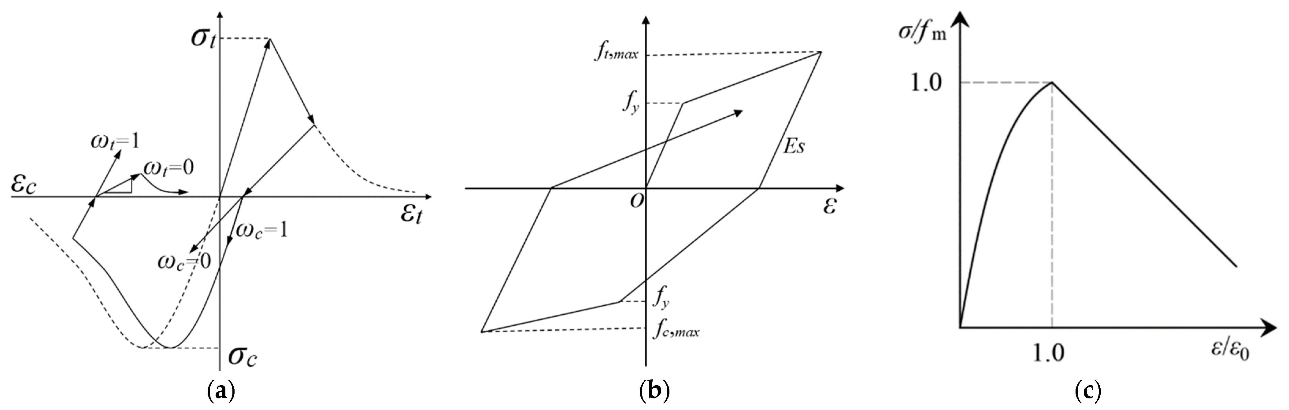
3.2. Constitutive Relationships of Materials

Referring to the code for design of concrete structures (GB50010—2010) [36], the Concrete Damaged Plasticity (CDP) model is elected as the constitutive model for concrete, exhibiting its stress-strain relationship in Figure 13a; the bilinear model is harnessed as the constitutive model for steel, illustrated in Figure 13b; and the constitutive relationship for masonry materials, as proposed by Liu [37], is showcased in Figure 13c.

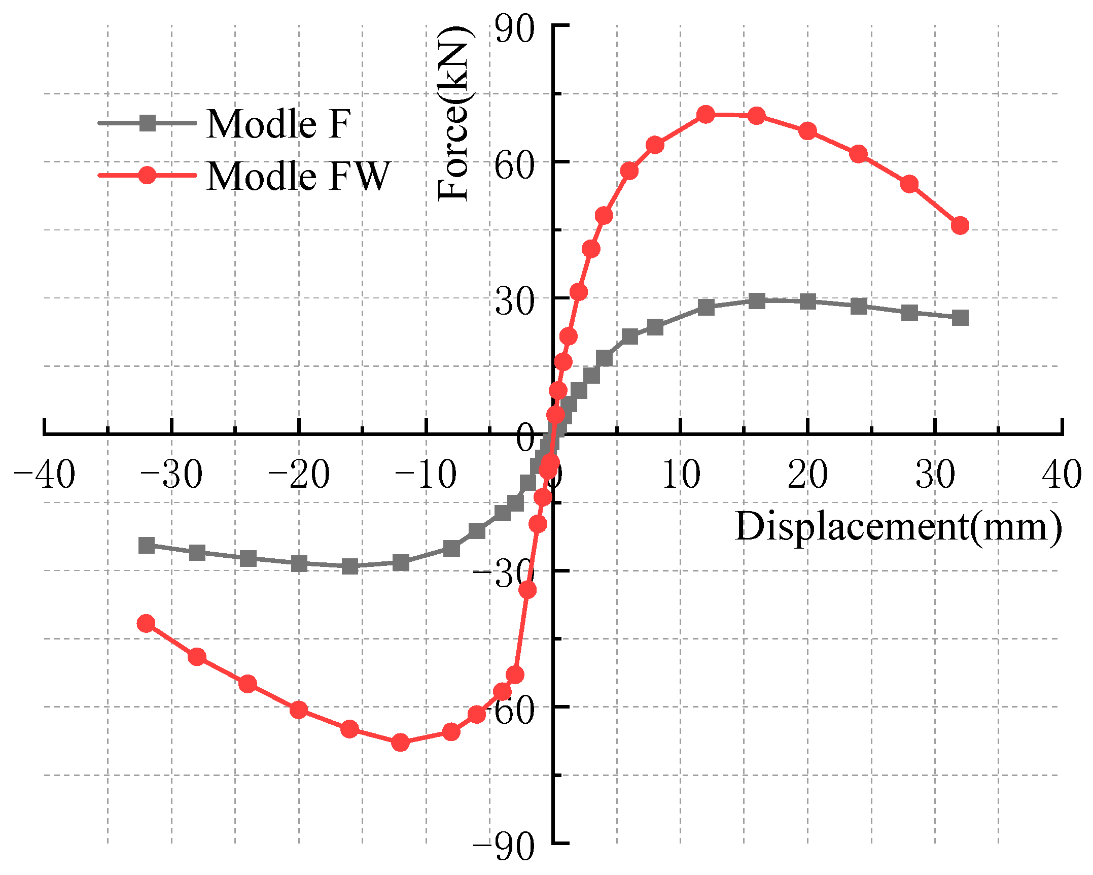
3.3. Model Validation

To corroborate the feasibility of the aforementioned modeling methodology, this paper undertakes an analysis of numerical simulation results and experimental phenomena. The column damage and wall–column separation showcased in the two sets of numerical models align significantly with the column failure and infilled wall behavior manifested in the test models, as shown in Figure 14. Moreover, the skeleton curves extrapolated from both the numerical and test models display consistent trends and a high degree of concordance. This substantiates that the numerical models constructed in this paper are precise, rational, and capable of mimicking the foundational mechanical behavior of reinforced concrete frame structures, as shown in Figure 15.

4. Parametric Modeling Analysis of RC Frame Structures Considering the Influence of Infilled Walls

To study the impact extent of infilled wall performance on the seismic capability of RC frame structures, 15 sets of numerical models are established with masonry materials and wall height as parameters. The materials for three types of infilled walls are adopted from test parameters found in the literature [40], as shown in Table 3 and Table 4.

4.1. Skeleton Curve Analysis under Different Working Cases

The skeleton curves corresponding to the three types of wall materials exhibit significant changes with the height of the infilled walls. Solid clay bricks have the most significant impact on the seismic behavior of the RC frame structure, followed by concrete hollow blocks, while autoclaved aerated concrete blocks have the least impact, as illustrated in Figure 16. The reason is that the elastic modulus of the autoclaved aerated concrete blocks is lower compared to the other two materials, resulting in a relatively weaker interaction between the blocks and the frame. The results of the ultimate bearing capacity, the initial stiffness, and the ductility coefficient under each working condition are listed in Table 5.
When the height ratio of the wall to the column is 0.2, the ultimate bearing capacities of models S1, C1, and A1 escalate by 28.67%, 27.24%, and 25.19%, respectively, above model B. The nearly analogous amplification across all three models suggests that the RC frame structure’s bearing capacity remains largely uninfluenced by the masonry material at this stage. However, as the wall height increases, the influence of the masonry material on the structural bearing capacity becomes progressively more pronounced. The ultimate bearing capacities for models S2, C2, and A2 witness an upsurge by 58.82%, 55.28%, and 51.60%, respectively; for models S3, C3, and A3, these figures increase by 100.60%, 89.94%, and 85.42%, respectively; for models S4, C4, and A4, they enhance by 152.23%, 131.30%, and 119.56%; and for models S5, C5, and A5, they leap by 228.57%, 185.51%, and 173.82%. Upon comparing the ultimate bearing capacities of structures with identical wall heights but varying wall materials, it is discernible that solid clay bricks catalyze the most substantial augmentation in the RC frame structure’s ultimate bearing capacity, followed by concrete hollow blocks, with autoclaved aerated concrete blocks contributing the least to the increase in ultimate bearing capacity.
Compared to Model B, the initial stiffness of Models S1, S2, S3, S4, and S5 escalates by 39.95%, 89.49%, 242.29%, 603.27%, and 1039.72%, respectively. Meanwhile, the initial stiffness of Models C1, C2, C3, C4, and C5 is enhanced by 36.45%, 85.28%, 195.79%, 537.38%, and 850.70%, respectively, and for Models A1, A2, A3, A4, and A5, it amplifies by 34.58%, 72.66%, 185.75%, 414.02%, and 608.88%, respectively. It is evident that the initial stiffness of the structure increases along with the rise in the height ratio of the wall to the column. Further analysis indicates that solid clay bricks exert the most substantial influence on augmenting the initial stiffness of the structure, followed by concrete hollow blocks, while autoclaved aerated concrete blocks have minimal impact on enhancing initial stiffness.
Upon the arrangement of infilled walls, the ductility of the structure decreases with the expansion in the height ratio of the wall to the column. Moreover, when the ratio surpasses 0.4, the rate of ductility reduction gradually escalates. As the height of the wall increases, the restraining effect of the infilled walls on the concrete columns intensifies, resulting in a decrease in the effective height of the columns, and the structure’s failure is mainly concentrated on the short column part that is not constrained by the walls. In comparison to Model B, under equivalent displacement conditions, the columns of the RC frame-structured infilled wall sustain more substantial damage. Nevertheless, once the infilled walls attain a certain height, the short column effect dwindles, and the column constraints tend to harmonize. As the strength of the infilled walls is inferior to that of the concrete and thus succumbs earlier, the confinement ability of the columns diminishes post-collapse, thereby tempering the rate of ductility reduction in the structure. When the infilled walls are fully constructed, the impact of masonry material on the frame structure is maximally pronounced.

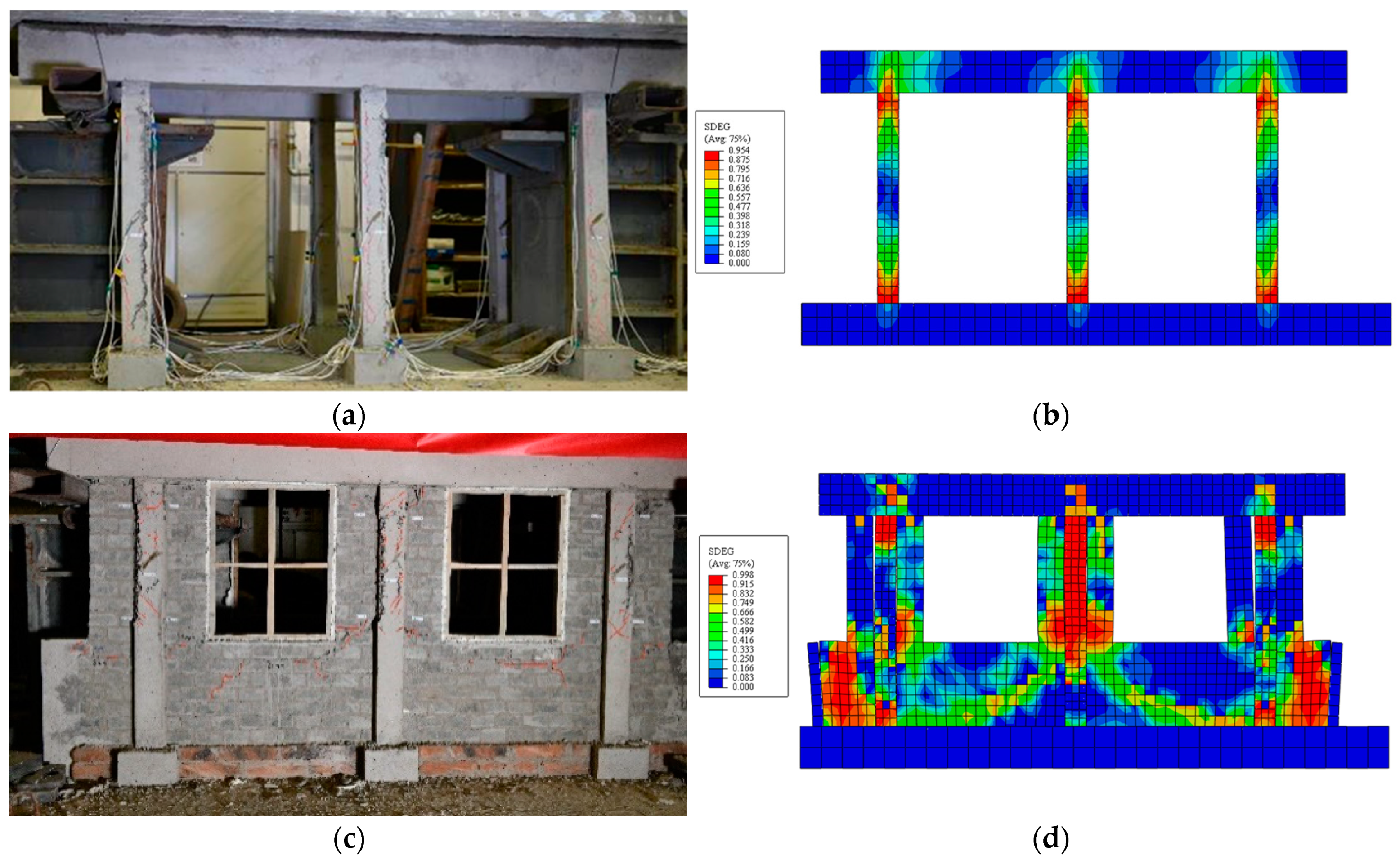
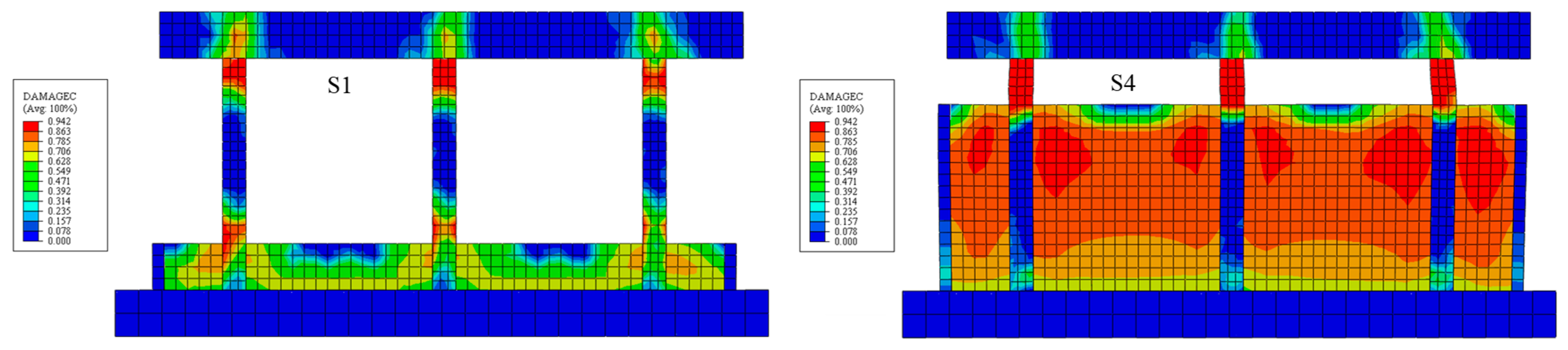
4.2. Failure Phenomena Analysis under Different Working Conditions

To delve deeper into the effect of masonry materials and wall heights on patterns of structural failure, this section analyzes the plastic damage cloud diagrams for models with wall-to-column ratios of 0.2 and 0.8. This analysis is predicated on the discussions presented in Section 3.1, as illustrated in Figure 17.
In Model B, bending failure is observed in the frame columns, demonstrating typical traits of plastic hinge failure at both the top and bottom ends of the frame column. Damage in Models S1, C1, and A1 is concentrated at the upper ends of the column and the connections of the infill wall-frame column, with the walls also experiencing a certain degree of damage. The plastic hinge regions at the column end bear resemblance to those in Model B, which indicates that the failure mode of the frame columns predominantly remains bending failure. Moreover, it is noted that the solid clay brick walls incur severe damage, whereas damage to the walls made of concrete hollow blocks and aerated concrete blocks is comparatively minor upon observing the infilled walls composed of three diverse materials. As the height of the masonry is increased, the confining effect of the infilled walls on the columns intensifies, thereby making the “short-column effect” more pronounced. The models S4, C4, and A4 demonstrate plastic damage within the free height range of the frame columns, displaying classic signs of shear failure, which suggests a shift in the failure mode of the frame columns from bending to shear failure. The walls made of solid clay bricks and concrete hollow blocks are significantly damaged; in contrast, the autoclaved aerated concrete block walls sustain less damage, which indicates that the RC frame structure’s seismic performance is less impacted by aerated concrete blocks, making them more suitable for infilled wall construction.

4.3. The Description of the Impact of Infilled Walls on the Seismic Performance of Structures

Based on the results of parametric studies, the presence of infill walls increases the load-bearing capacity and stiffness of structures but reduces their ductility. As the height of the masonry increases, the effective height of the concrete columns decreases. When the wall-to-column height ratio is 0.2, the influence of the masonry wall on the seismic performance of the composite structure is not significant. However, when the wall-to-column height ratio reaches 0.6, the damage mode of the columns shifts from flexural to shear failure. For wall-to-column height ratios of 0.4 and below, the difference in the impact of masonry materials on the seismic performance of the composite structure is not significant. As the wall-to-column height ratio exceeds 0.6, the differences become more pronounced, with aerated concrete block infill walls having the least impact on the seismic performance of the beam-to-column composite structure.

5. Conclusions

This paper studies the effect of different wall-to-column height ratios and various wall materials on the seismic performance of frame structures by conducting quasi-static tests on two sets of two-span RC frame structure models with a similitude ratio of 1:4 and numerical simulation on 15 sets of frame structures with infilled walls. In addition, the failure characteristics, hysteretic curve attributes, and skeleton curve features of each frame model are compared. An analysis of ductility, stiffness degradation, strength deterioration, and energy dissipation capacity is conducted. The following conclusions are drawn based on the test and simulation results:
(1)
The experimental findings reveal that the model with half-height infilled walls exhibits a 138.54% increase in ultimate load-carrying capacity and a 214.81% enhancement in initial stiffness compared to the pure frame model. However, the ductility of the structure notably decreases, along with a reduction in the free height of the frame columns, which makes the structure more prone to shear failure during an earthquake, thereby intensifying the overall extent of structural damage.
(2)
At a wall-to-column height ratio of 0.2, the seismic performance of the RC frame structure is marginally influenced by the masonry materials. With the height of the infilled walls increasing, there is an upsurge in both the bearing capacity and the initial stiffness of the structure, with a concomitant reduction in ductility, while the rate of ductility decreases and stiffness degradation increases. When the wall-to-column height ratio reaches 0.6, the failure mode of the frame columns transitions from flexural failure to shear failure. At a wall-to-column height ratio of 0.8, the “short-column effect” is notably distinct, and the damage degree of the aerated concrete block wall is the lightest at this time. When the height of the infilled walls continues to increase, the short-column effect diminishes, and the rates of decline in both structural ductility and stiffness degradation decelerate.
(3)
The influence of masonry materials on the seismic performance of structures is not significantly different when the wall-to-column height ratio is 0.4 or below. However, as the wall-to-column height ratio exceeds 0.6, the differences in their impact on seismic performance become increasingly apparent. Under the identical height ratio of wall to column, the seismic performance of the structure is most significantly influenced by solid clay bricks, followed by concrete hollow blocks, and minimally by aerated concrete blocks. Consequently, it is advisable to prioritize aerated concrete blocks as the preferred material for constructing infilled walls in practical engineering implementations.
(4)
The properties of commonly used masonry materials substantially affect the seismic performance of structures. Therefore, it is necessary to identify a material that exerts minimal effect on the reduction of concrete stiffness and the alteration of stress in steel reinforcements. This material should fulfill operational demands while reducing the influence of infilled walls on the structure’s seismic performance.

Author Contributions

Conceptualization and methodology, Y.Z. (Yang Zhou) and X.Z.; software and visualization, X.Z. and X.L.; validation and formal analysis, Y.Z. (Yang Zhou); investigation and resources, Y.Z. (Yaoyu Zheng) and Z.Q.; data curation and writing—original draft preparation, X.Z.; writing—review and editing, Y.Z. (Yang Zhou) All authors have read and agreed to the published version of the manuscript.

Funding

This research is funded by the Foundation of Science and Technology Innovation Program for Postgraduate students in IDP subsidized by Fundamental Research Funds for the Central Universities (ZY20240321), the Foundation of Research Program of Higher Education Institutions in Hebei Province (ZC2024116), the Foundation of Science and Technology Research and Development Program Project of Langfang City (2023011079), and National Natural Science Foundation of China (52278489).

Data Availability Statement

The raw data supporting the conclusions of this article will be made available by the authors on request.

Conflicts of Interest

Author Zhengxin Qi was employed by the company China Nuclear Industry 24 Construction Co., Ltd. The remaining authors declare that the research was conducted in the absence of any commercial or financial relationships that could be construed as a potential conflict of interest.

References

  1. Zhou, Y.; Qin, Z.X.; Guo, X. Progress and prospect on seismic collapse-resistant capacity of RC frame structures. J. Disaster Prev. Mitig. Eng. 2021, 41, 860–873. [Google Scholar]
  2. Ditommaso, R.; Lamarucciola, N.; Ponzo, F.C. Prediction of the fundamental period of infilled RC framed structures considering the maximum inter-story drift at different design limit state. Structures 2024, 63, 106422. [Google Scholar] [CrossRef]
  3. Li, H.N.; Xiao, S.Y.; Huo, L.S. Damage investigation and analysis of engineering structures in the Wenchuan earthquake. J. Build. Struct. 2008, 29, 10–19. [Google Scholar]
  4. Wang, T.; Lei, Y.; Zhang, Y.; Kong, Z. Seismic damage analysis of school buildings in Lushan earthquake. J. Earthq. Eng. Eng. Vib. 2013, 33, 36–47. [Google Scholar]
  5. Huang, S.N.; Yuan, Y.F.; Meng, Q.L. Study on seismic resistance of rural houses based on earthquake damage to buildings in Yushu earthquake. World Earthq. Eng. 2011, 27, 77–82. [Google Scholar]
  6. Yi, P.; Chi, Z.; Xian, G.; Chang, Z.; Zhuo, J. Earthquake damage investigation and analysis of the RC frame structures in Taiwan Meinung Ms 6.7 earthquake. China Civ. Eng. J. 2016, 49, 13–18. [Google Scholar]
  7. Jingshan, B.O.; Xiaobo, L.I.; Duan, Y. Investigation and analysis of seismic damage to school buildings in Ms 7.0 Jiuzhaigou earthquake. Earthq. Eng. Eng. Dyn. 2018, 38, 120–128. [Google Scholar]
  8. Dong, X.Y.; Guo, X.; Luo, R.F.; Zhang, Q.Z.; Zhang, J.; Dong, C.; Wang, B. Seismic damage investigation structural force analysis of Luding Ms 68. J. Build Struct. 2023, 44, 11–19. [Google Scholar]
  9. Al-Chaar, G.; Issa, M.; Sweeney, S. Behavior of masonry-infilled nonductile reinforced concrete frames. J. Struct. 2002, 128, 1055–1063. [Google Scholar] [CrossRef]
  10. Hashemi, A.; Mosalam, K.M. Shake-table experiment on reinforced concrete structure containing masonry infill wall. Earthq. Eng. Struct. D. 2006, 35, 1827–1852. [Google Scholar] [CrossRef]
  11. Lin, X.; Pan, P.; Ye, L.; Lu, X.; Zhao, S. Analysis of the damage mechanism of a typical RC frame in Wenchuan Earthquake. China Civ. Eng. J. 2009, 42, 13–20. [Google Scholar]
  12. Guo, Z.X.; Huang, Q.X.; Wei, R.F.; Liu, Y. Experimental study of the seismic behavior of irregularly brick infilled RC frames. China Civ. Eng. J. 2010, 43, 46–54. [Google Scholar]
  13. Kakaletsis, D.J.; Karayannis, C.G. Experimental Investigation of Infilled Reinforced Concrete Frames with Openings. ACI Struct. J. 2009, 106, 132–141. [Google Scholar]
  14. Tasnimi, A.A.; Mohebkhah, A. Investigation on the behavior of brick-infilled steel frames with openings, experimental and analytical approaches. Eng. Struct. 2011, 33, 968–980. [Google Scholar] [CrossRef]
  15. Mansouri, A.; Marefat, M.S.; Khanmohammadi, M. Experimental evaluation of seismic performance of low-shear strength masonry infills with openings in reinforced concrete frames with deficient seismic details. Struct. Des. Tall Spec. Build. 2014, 23, 1190–1210. [Google Scholar] [CrossRef]
  16. Jin, H. Research on Seismic Failure Mechanisms and Key Aseismic Measures for Masonry-Infilled RC Frame Structures. Ph.D. Thesis, Institute of Engineering Mechanics, China Earthquake Administration Harbin, Harbin, China, 2014. [Google Scholar]
  17. Yang, W.S. Experimental Study on Collapse Mechanism of Multi-Story RC Frame School Buildings. Ph.D. Thesis, Institute of Engineering Mechanics, China Earthquake Administration Harbin, Harbin, China, 2015. [Google Scholar]
  18. Zovkic, J.; Sigmund, V.; Guljas, I. Cyclic testing of a single bay reinforced concrete frames with various types of masonry infill. Earthq. Eng. Struct. Dyn. 2013, 42, 1131–1149. [Google Scholar] [CrossRef]
  19. Siddiqui, U.A.; Sucuoglu, H.; Yakut, A. Seismic performance of gravity-load designed concrete frames infilled with low-strength masonry. Earthq. Struct. 2015, 8, 19–35. [Google Scholar] [CrossRef]
  20. Dautaj, A.D.; Kadiri, Q.; Kabashi, N. Experimental study on the contribution of masonry infill in the behavior of RC frame under seismic loading. Eng. Struct. 2018, 165, 27–37. [Google Scholar] [CrossRef]
  21. Jiang, H.J.; Mao, J.J.; Liu, X.J. Experimental study on seismic performance of masonry infilled RC frame with different types of connections. J. Build Struct. 2014, 35, 60–67. [Google Scholar]
  22. Zhou, X.J. Study on Seismic Behavior of Flexible Connection Frame Structure Infilled with New Masonry. Ph.D. Thesis, Tianjin University, Tianjin, China, 2014. [Google Scholar]
  23. Zhou, X.J.; Jiang, X.L.; Xu, D.D.; Song, J.K.; Yang, C.H. Experimental research on seismic behavior of flexible connection frame structure infilled with new masonry. Word Earthq. Eng. 2015, 31, 58–68. [Google Scholar]
  24. Teguh, M. Experimental evaluation of masonry infill walls of RC fra me buildings subjected to cyclic loads. Procedia Eng. 2017, 171, 191–200. [Google Scholar] [CrossRef]
  25. Baghi, H.; Oliveira, A.; Valença, J.; Cavaco, E.; Neves, L.; Júlio, E. Behavior of reinforced concrete frame with masonry infill wall subjected to vertical load. Eng. Struct. 2018, 171, 476–487. [Google Scholar] [CrossRef]
  26. Onat, O.; Correia, A.A.; Lourenço, P.B.; Koçak, A. Assessment of the combined in-plane and out-of-plane behavior of brick infill walls within reinforced concrete frames under seismic loading. Earthq. Eng. Struct. Dyn. 2018, 47, 2821–2839. [Google Scholar] [CrossRef]
  27. Guljaš, I.; Penava, D.; Laughery, L.; Pujol, S. Dynamic tests of a large-scale three-story RC structure with masonry infill walls. J. Earthq. Eng. 2020, 24, 1675–1703. [Google Scholar] [CrossRef]
  28. Binici, B.; Canbay, E.; Aldemir, A.; Demirel, I.O.; Uzgan, U.; Eryurtlu, Z.; Bulbul, K.; Yakut, A. Seismic behavior and improvement of autoclaved aerated concrete infill walls. Eng. Struct. 2019, 193, 68–81. [Google Scholar] [CrossRef]
  29. Zhai, C.H.; Wang, X.M.; Kong, J.C.; Wei, Y.L.; Jin, W.; Zhao, Y. Progress prospect of seismic performance of masonry-infilled RC frames. J. Harbin Inst. Technol. 2018, 50, 1–13. [Google Scholar]
  30. Zhang, M.H.; Pang, L.; Ding, J.N.; Wang, D. A review of the methods of strengthening RC frames with masonry infilled wall structures. Earthq. Eng. Eng. Dyn. 2021, 41, 53–62. [Google Scholar]
  31. Almasabha, G.; Chao, S.H. A New Reinforcing Configuration for Achieving High-Ductility High-Strength Rectangular Squat Structural Walls. ACI Struct. J. 2023, 120, 253. [Google Scholar]
  32. Chao, S.H.; Almasabha, G.; Price, B.; Jiansinlapadamrong, C. A Horizontal Stiffener Detailing for Shear Links at the Link-to-Column Connection in Eccentrically Braced Frames. J. Struct. Eng. 2023, 149, 04023114. [Google Scholar] [CrossRef]
  33. JGJ/T101-2015; Specification for Seismic Test of Buildings. Ministry of Housing and Urban-Rural Development of the People’s Republic of China: Beijing, China, 2015.
  34. Wang, D.; Zhao, H.Q.; Lu, X.L. Loading protocols for quasi-static test of structural components for buildings. Sichuan Build. Sci. 2014, 40, 54–59. [Google Scholar]
  35. Feng, P.; Cheng, S.; Bai, Y.; Ye, L. Mechanical behavior of concrete filled square steel tube with FRP confined concrete core subjected to axial compression. Compos. Struct. 2015, 123, 312–324. [Google Scholar] [CrossRef]
  36. GB 50011-2010; Code for Seismic Design of Buildings. Ministry of Housing and Urban-Rural Development of the People’s Republic of China: Beijing, China, 2010.
  37. Liu, G.Q.; Yan, Y.Q.; Shi, C.X. Research on the unified model of the compressive constitutive relations of masonry. J. Hunan Univ. Nat. Sci. 2009, 36, 6–9. [Google Scholar]
  38. Joyner, W.B.; Chen, A.T.F. Calculation of nonlinear ground response in earthquakes. Bull. Seismol. Soc. Am. 1975, 65, 1315–1336. [Google Scholar]
  39. Clough, R.W. Effect of Stiffness Degradation on Earthquake Ductility Requirements, 1st ed.; University of California: Berkeley, CA, USA, 1966. [Google Scholar]
  40. Huang, Q.X. Study on Seismic Behavior and Elastic-Plastic Analysis Method for Seismic Responses of RC Frame Infilled with New Masonry; Huaqiao University: Quanzhou, China, 2011. [Google Scholar]
Figure 1. Geometric dimensions and reinforcement configuration of model F (mm).
Buildings 14 01907 g001
Figure 2. F frame model.
Buildings 14 01907 g002
Figure 3. FW frame model.
Buildings 14 01907 g003
Figure 4. The strain gauge layout of F frame model.
Buildings 14 01907 g004
Figure 5. The strain gauge layout of FW frame model.
Buildings 14 01907 g005
Figure 6. Schematic diagram of the loading system.
Buildings 14 01907 g006
Figure 7. Failure in Columns of F model. (a) Partial damage. (b) Overall damage.
Buildings 14 01907 g007aBuildings 14 01907 g007b
Figure 8. Failure of model FW. (a) Partial damage. (b) Overall damage.
Buildings 14 01907 g008aBuildings 14 01907 g008b
Figure 9. Hysteresis curves of each test model. (a) Hysteresis curve of model F; (b) hysteresis curve of model FW.
Buildings 14 01907 g009
Figure 10. Skeleton curves of each model.
Buildings 14 01907 g010
Figure 11. Stiffness degradation curves of each model.
Buildings 14 01907 g011
Figure 12. Numerical models. (a) NF frame model; (b) NFW frame model.
Buildings 14 01907 g012
Figure 13. Constitutive relationships. (a) Constitutive relationships of concrete [38]; (b) constitutive relationships of steel [39]; (c) constitutive relationships of masonry [36].
Buildings 14 01907 g013
Figure 14. Comparison of failure between test models and numerical models. (a) Failure modes of model F; (b) plastic damage to model NF; (c) failure modes of model FW; (d) plastic damage to model NFW.
Buildings 14 01907 g014
Figure 15. Comparison of skeleton curves between numerical models and test models.
Buildings 14 01907 g015
Figure 16. Skeleton curves of various models.
Buildings 14 01907 g016
Figure 17. Plastic damage cloud diagrams.
Buildings 14 01907 g017aBuildings 14 01907 g017b
Table 1. Performance parameters of materials (MPa).
Test GroupfcuEcfycfufybfsufb
F13.1920,700.00150.00260.00743.50201.006.10
FW13.0320,537.00-----
Note: fcu: Compressive strength of the cube. Ec: Elastic modulus of concrete. fyc: Yield strength of column reinforcement. fu: Ultimate tensile strength of column reinforcement. fyb: Tensile strength of beam reinforcement. fsu: Ultimate tensile strength of stirrup. fb: Compressive strength of the masonry brick.
Table 2. The comparative results of model bearing capacity and deformation ability.
Test GroupΔu (mm)Δy (mm)Fmax (kN)μK (kN/mm)
F32.05.728.85.618.1
FW24.05.068.74.825.5
Note: Δu: ultimate displacement which is the displacement corresponding to the load dropping to 85% of the ultimate load. Δy: yield displacement which is determined by the farthest point method [35]. Fmax: ultimate load. μ: ductility coefficient, μ = Δuy. K: initial stiffness.
Table 3. Material parameters for three types of walls.
GroupsCompressive Strength/MPaElastic Modulus/MPa
Solid clay brick5.404622
Autoclaved aerated concrete block2.523102
Concrete hollow block2.305270
Table 4. Classification of working cases of infilled wall frame structures with different masonry heights.
GroupsPure FrameHeight Ratio of Wall-to-Column
0.20.40.60.81.0
Solid clay brickBS1S2S3S4S5
Autoclaved aerated concrete blockC1C2C3C4C5
Concrete hollow blockA1A2A3A4A5
Table 5. Results of numerical simulation.
GroupUltimate Bearing Capacity (kN)Initial Stiffness (kN/mm)Ductility Coefficient
ValueRaise (%)ValueRaise (%)ValueRaise (%)
B29.45-4.28-4.68-
S137.8928.67%5.9939.95%4.65−1.64%
S246.7758.82%8.1189.49%4.55−2.78%
S359.08100.60%14.65242.29%4.30−8.12%
S474.28152.23%30.10603.27%3.76−19.66%
S596.76228.57%48.781039.72%3.38−27.78%
C137.4727.24%5.8436.45%4.66−0.43%
C245.7355.28%7.9385.28%4.61−1.50%
C355.9489.94%12.66195.79%4.36−6.84%
C468.12131.30%27.28537.38%3.92−16.24%
C584.08185.51%40.69850.70%3.70−20.94%
A136.8725.19%5.7634.58%4.66−0.43%
A244.6451.60%7.3972.66%4.64−0.85%
A354.6085.42%12.23185.75%4.44−5.13%
A464.66119.56%22.00414.02%4.13−11.75%
A580.64173.82%30.34608.88%4.01−14.32%
Disclaimer/Publisher’s Note: The statements, opinions and data contained in all publications are solely those of the individual author(s) and contributor(s) and not of MDPI and/or the editor(s). MDPI and/or the editor(s) disclaim responsibility for any injury to people or property resulting from any ideas, methods, instructions or products referred to in the content.

