Abstract
Reinforced concrete (RC) infrastructure is an essential part of modern civilization. However, the serviceability of RC infrastructure in extreme weather has become challenging due to the susceptibility of the initiation of cracks. Hence, the demand for strengthening and retrofitting RC infrastructure is rapidly increasing. The RC specimens strengthened with existing externally bonded reinforcement (EBR) and near-surface mounted (NSM) techniques; however, they suffered a prematurely brittle or debonding failure. Hence, the merging of side near surface mounting (SNSM) and side externally bonded reinforcement (S-EBR) methods ended up resulting in the development of an innovative side hybrid (SH) strengthening approach that is designed to overcome these drawbacks. In this investigation, six rectangular RC beam specimens were flexurally strengthened utilizing carbon fiber-reinforced polymer (CFRP) with the SH technique, and then four-point bending experiments were performed to failure. The beam specimens were categorized into two types: (I) control specimens and (II) specimens strengthened with the SH technique applying CFRP varying bonded length from 1600 mm to 1900 mm. The initial cracking, yield, and ultimate load-bearing capabilities, deflection, failure modes, cracking characteristics, stiffness, energy absorption capacity, and strain on the utmost fiber of concrete, the tensile strain of major steel rebars, SNSM bars, and S-EB plates were assessed from the experimental investigation. The SH technique substantially improved the flexural performance of the beam specimens. The initial cracking load, yield, and ultimate load-bearing capabilities were enhanced remarkably by 387%, 108%, and 163%, respectively, over the reference specimen. The flexural stiffness and energy absorption capacity substantially improved by 120% and 103%, respectively, compared with the reference specimen.
Keywords:
side hybrid; strengthening; flexural enhancement; RC; CFRP; stiffness; energy absorption capacity 1. Introduction
Reinforced concrete is extensively used for constructing different types of structures all over the world because it has excellent characteristics in terms of mechanical properties and is more economical than steel structures [1]. RC structures suffered deterioration complications, such as reinforcement corrosion that triggers cracking and concrete cover spalling off and significantly defeat of load-bearing capability, which led to the failure of the structures before the achievement of targeted service life when structures were subjected to hostile exposure circumstances [2,3,4].
Various strengthening techniques were utilized for the restoration and strengthening of RC structures. These techniques involved the upgrading or strengthening of structures for shear or flexure by external bonding reinforcement (EBR) [5,6,7] and near-surface mounting (NSM) [8,9,10,11] using fiber-reinforced polymer (FRP) reinforcement. In the EBR technique, steel plates [12] or FRP laminates or sheets [13] are glued to the tension face of the members to be strengthened. In the meantime, using the NSM technique, FRP rebars or strips are incorporated in concrete through pre-cut grooves in the cover of the concrete and afterward sealed up with adhesives [14,15].
Premature debonding emerging from elevated interfacial shear stresses involving the FRP and the concrete surface at the strengthened reinforcement curtailment position exhibited several difficulties for the EBR method [16,17]. Moreover, the NSM technique offers several potential benefits outlined in previous studies, including enhanced safeguarding of FRP counter to external forces, applicability for reinforcing areas with detrimental moments, and minimal impact on the aesthetic appearance of the structural members [18,19,20]. The bond between the concrete matrix and reinforcing rebars was a crucial factor that determined whether or not such modification material might be exploited in structural strengthening [21,22].
Numerous experimental studies [23,24,25] have revealed that the NSM technique exhibits superior strengthening efficacy compared to the EBR technique employing FRP systems. This superiority slows from the enhanced FRP-concrete bond performance, characterized by a greater anchoring capacity to the FRP, achievable through the NSM approach. By delaying FRP debonding and, in certain cases, even achieving FRP tensile rupture, the NSM method allows for more efficient utilization of reinforcement material, resulting in an increased proportion of FRP strain at rupture to its peak strain. Additionally, the NSM technique offers the added benefit of significantly reducing the likelihood of damage caused by vandalism, mechanical impacts, and aging consequences, as the FRP is shielded by the concrete cover. Moreover, once employing the NSM approach, the aesthetic manifestation of a structurally RC component remains largely unchanged by the strengthening involvement [26,27].
Sharaky et al. [28] assessed the flexural performance of RC beams rehabilitated with NSM using both carbon fiber-reinforced polymer (CFRP) and glass fiber-reinforced polymer (GFRP) rebars. In all cases, the strengthened beam specimens failed owing to debonding. Notably, amongst the beams upgraded with double grooves, those reinforced with CFRP showed separation of concrete cover, whereas those upgraded with GFRP experienced concrete splitting.
Al-Mahmoud, F., et al. [29] computed the bending responses of RC beam samples strengthened by the NSM-CFRP system. The bending strength was improved regardless of the different groove packing glue and concrete grade. The withdrawal with splitting and peeling-off types of debonding failure modes was exhibited for strengthened beams.
Tang, W. C., et al. [30] explored the flexural attributes of normal beam specimens and lightweight beam specimens (through polystyrene aggregate) strengthened with NSM-GFRP rods. The debonding failure pattern occurred for strengthened beam specimens due to shear through the splitting of the adhesive or NSM-GFRP bars rupture.
Bilotta, A., et al. [31] computed the efficiency for flexurally strengthened RC beam specimens employing NSM and EBR methods using CFRP. The modes of collapse of the strengthened beams were premature, such as crack debonding, critical diagonal debonding, end debonding, and split concrete covering.
Hosen, M. A., et al. [32] introduced the SNSM strengthening method as a solution to address the drawbacks of the NSM system, utilizing both steel and CFRP rebars. The SNSM approach encompasses creating grooves in the concrete cover on two longitudinal sides (tension face) of the beam sample utilizing a specialized concrete saw, followed by the insertion of CFRP rebars with adhesive engagement. According to the experimental findings, the SNSM strengthening system profoundly enhanced the initial cracking, yield, and maximum load-carrying capabilities of the beam samples, increasing them by approximately 3.17, 2.0, and 2.38 times, respectively, assessed with the unstrengthened specimens. Additionally, it outstandingly improved the breakdown modes of the beam samples.
Furthermore, Hosen, M. A., et al. [33] examined the viability of intensifying the flexural strength of lightweight RC beam samples with pre-cracked and without pre-cracked, using the new S-EBR technique employing CFRP fabric. Eight full-scale RC samples were constructed, strengthened, and exposed to a four-point bend loading until breakdown. The study considered various parameters, including internal main reinforcement percentage, the proportion of pre-cracking loads, and the impact of extreme loads on rupture functioning. The application of the S-EBR strengthening method utilizing CFRP fabric notably improved the rupture strength of pre-cracked and non-pre-cracked lightweight RC samples assessed with the reference sample. Furthermore, the analytical model’s predictions of flexural capacity aligned reasonably well with the experimental findings.
Therefore, in an effort to address the drawbacks associated with existing EBR and NSM techniques, the current investigation aims to introduce the innovative side hybrid (SH) technique, which combines aspects of SNSM and S-EBR methods. The objective is to assess the potentiality of the SH technique for enhancing the flexural load-bearing capabilities and improving the serviceability of RC structural elements. This study examines the structural attributes of RC beam elements strengthened by applying the SH technique with CFRP composites. The strengthened beam specimens undergo experiments in four-point bending conditions. Varying bonded lengths of SNSM bars and S-EBR plates are utilized for the SH technique to strengthen the RC beams. The analysis of load-carrying capability, deflection, and strain values aims to provide insights into the flexural stiffness, energy absorption capacity, cracking characteristics, and failure modes exhibited by the tested beam specimens.
2. Research Significance
The strengthening or upgrading of existing reinforced concrete (RC) infrastructures offers a significant opportunity to reduce carbon footprints and advance sustainability within the construction industry [34,35]. Currently, the rehabilitation or maintenance systems for RC infrastructure encounter challenges, including premature failure, before reaching their ultimate strength [36,37]. Hence, there is a pressing requirement to develop novel techniques to strengthen and address these existing systems (especially NSM and EBR) drawback issues. Through strategic approaches like strengthening, repairing, and adopting advanced materials, these structures can be modernized to meet contemporary efficiency standards while reducing the necessity for new infrastructure construction. Opting for strengthening or upgrading instead of demolition and reconstruction can lead to notable reductions in carbon emissions associated with material manufacturing, transportation, and waste disposal. Additionally, incorporating sustainable practices in strengthening existing infrastructures, such as integrating renewable energy sources, optimizing energy efficiency, and utilizing waste-recycled materials, enhances environmental advantages. Therefore, embracing innovative Side Hybrid (SH) strengthening approaches not only prolongs the lifespan of existing RC infrastructures but also fosters a more sustainable built environment, aligning with global initiatives to combat climate change.
3. Experimental Programme
The experimental inspection comprised six rectangular RC beam specimens, one of which served as the reference beam specimen, while the other beam specimens underwent strengthening using the SH technique. The key testing parameters included the bonded length of the strengthening reinforcement (ranging from 1600 mm to 1900 mm) and the width of the S-EBR plates (50 mm and 75 mm). The specific test configurations are outlined in detail in Table 1.

Table 1.
Test matrix for strengthening configurations.
3.1. Materials Properties
3.1.1. Normal Strength Concrete (NSC)
This research employed NSC for beam specimens’ fabrication. The concrete was made using normal Portland cement, well-graded artificial sand as fine aggregate (FA), crushed stone (with an utmost size of 20 mm) as coarse aggregate (CA), and potable tap water. The concrete specimens exhibited compressive strength, splitting tensile strength, modulus of rupture, and Young’s modulus of elasticity values of 60 MPa, 4.50 MPa, 5.80 MPa, and 36,500 MPa, respectively [38].
3.1.2. Reinforcing Steel Rebars
10 mm and 12 mm diameter high-strength deformed steel rebars were utilized as the major longitudinal reinforcement and hanger reinforcement in constructing the RC beam specimens’ casing. Transverse reinforcement was provided by mild steel rebars with a diameter of 6 mm. Tensile strength tests were conducted utilizing an Instron Universal Machine to compute the mechanical characteristics of the reinforcement. The experimental results revealed yield strengths of 550 MPa, 520 MPa, and 300 MPa for the 12 mm, 10 mm, and 6 mm diameter rebars, respectively. Additionally, the Young’s modulus of elasticity for the reinforcement was found to be 200,000 MPa [39].
3.1.3. CFRP Rebars and Plate
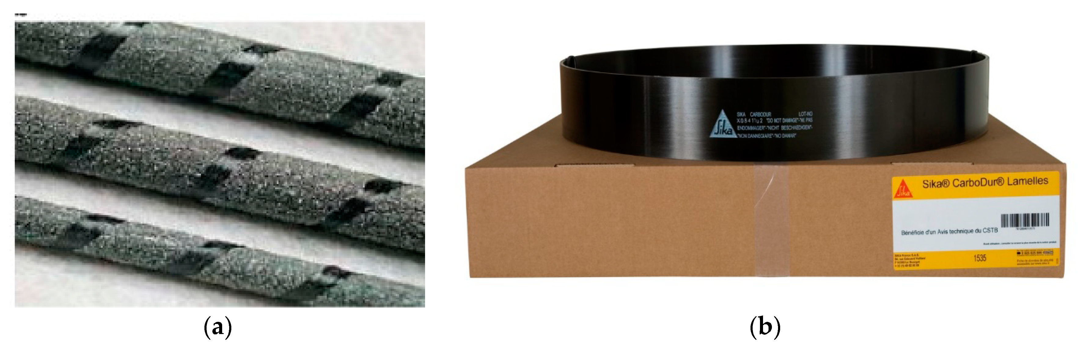
The RC beam specimens were strengthened in flexure by utilizing pultruded sand-coated CFRP rebars (Figure 1a) with a diameter of 8 mm and a bulk density of 16 kN/m3, employing the side hybrid (SH) technique. The manufacturer provided the mechanical properties of the CFRP rebars, which included yield strength, ultimate tensile strength, and Young’s modulus of elasticity. The rebars exhibited yield and ultimate tensile strengths of 1250 MPa and 1860 MPa, respectively, along with a Young’s modulus of elasticity of 132,000 MPa [40].
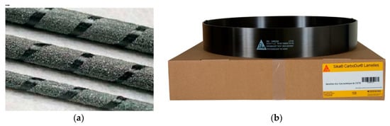
Figure 1.
Strengthening reinforcement: (a) CFRP bars; (b) CFRP plate.
Sika Carbodur® pultruded CFRP plates (Figure 1b) were employed by the SH technique for strengthened RC beam specimens. The plates had a thickness and width of 0.0012 m and 0.10 m, respectively. The CFRP plates exhibited an average tensile strength, Young’s modulus of elasticity, and breaking strain of 3100 MPa, 165,000 MPa, and 1.7%, respectively [41].
3.1.4. Epoxy Adhesives
In the SH strengthening technique, Sikadur-30 structural adhesive (depicted in Figure 2) was utilized to adhere the concrete surface to both CFRP bars and CFRP plates. It comprises two components, white and black, with a mixing ratio of 3(B):1(A). According to the manufacturer’s specifications, Sikadur-30 possesses shear, bond, compressive, and tensile strengths, along with a Young’s modulus of elasticity of 19 MPa, 21 MPa, 95 MPa, 31 MPa, and 11,200 MPa, respectively [42].

Figure 2.
Epoxy adhesive.
3.2. Beam Specimens Preparation
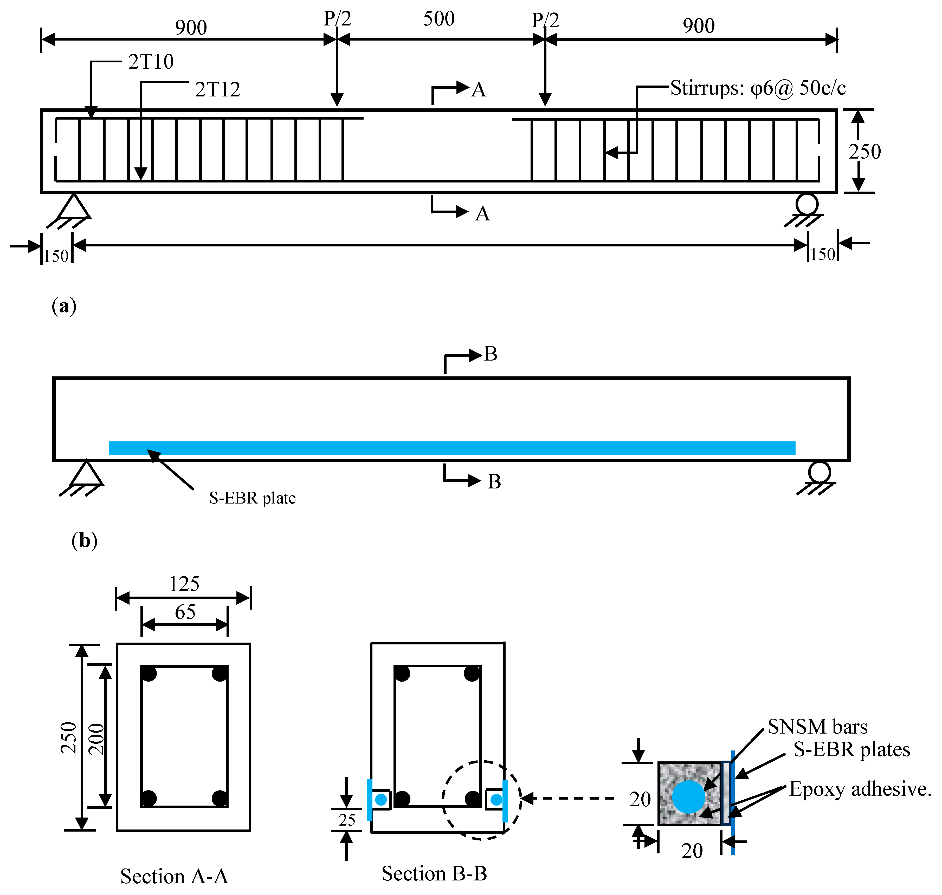
The experimental phase involved six rectangular RC beam specimens measuring 125 mm × 250 mm in dimensions. The total span length of the beams was 2.3 m, with a functioning span length of 2.0 m. The main reinforcement on the tension face encompassed two 12 mm diameter rebars, while in the compression region, there were two 10 mm diameter rebars acting as hanger reinforcement. The transverse reinforcement with a diameter of 6 mm was placed at 50 mm intervals to promote a flexural mode of failure [43]. Figure 3 illustrates the cross-sectional configuration, arrangement of reinforcement, loading setup, and support arrangement of the beam specimens used in these laboratory investigations.

Figure 3.
Geometry and detailing of the beam specimens: (a) Control beam specimen; (b) Strengthened beam specimen.
3.3. Strengthening Procedure
The bond length of the strengthening reinforcement plays a crucial factor in enhancing the structural responses of the structural elements in both EBR and NSM methods [44,45,46]. Hence, the variation of bonded length from 1600 mm to 1900 mm of the CFRP (rebars and plates) reinforcement for strengthening RC beams was executed in this SH technique for the evaluation of flexural responses. In the SH technique, when applying S-EBR plates, careful preparation of the concrete surface is essential to safeguard effective gluing between the plate and the concrete. Any oily residues, loose debris, dirt, or other extraneous particles must be thoroughly cleaned from the gluing concrete face of the beam specimens. Moreover, the smoothness of the concrete surface’s coarse aggregate would have to be apparent. To achieve this, the bonding surfaces of the concrete were roughened utilizing a scabbler machine before cutting grooves for SNSM bars. The SNSM groove dimensions were 20 mm × 20 mm for the SH strengthening technique. At first, the CFRP rebars were introduced into the SNSM grooves with epoxy to ensure the proper placement of the rebars, and the surface was flattened using a spatula. After affirming the curing time of the specimens for the SNSM-CFRP rebars approach, the beam surface (specified area for S-EBR) was polished and processed for the strengthening of the S-EBR technique utilizing CFRP plates. A thin coating of epoxy adhesive was employed to the required concrete plane, and CFRP plates were fixed with the use of a specialized roller. The specimens had left seven days period for curing the adhesive and had attained its full strength.
3.4. Instrumentation and Test Setup
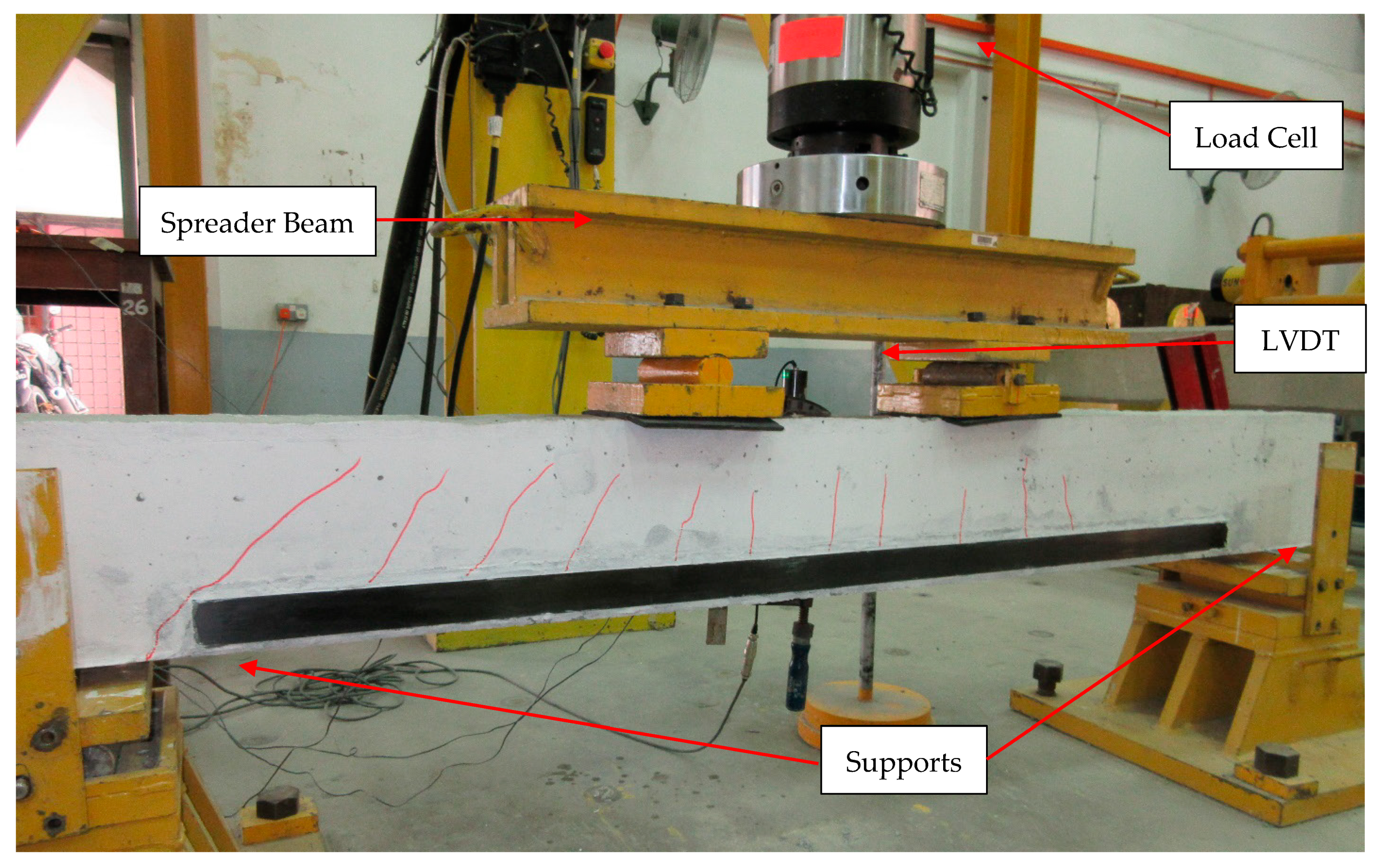
The experimental investigations were conducted in a massive structure laboratory utilizing an Instron Universal Machine with a flexural loading capability of 250 kN, as depicted in Figure 4. Both the unstrengthened reference and strengthened beam specimens underwent testing in four-point loading under monotonic conditions, employing simply supported ends. A displacement control procedure with an actuator controlling speed of 1.5 mm/min was maintained, and load enhancements were accurately captured by the load cell until specimen failure. One linear variable displacement transducer (LVDT) was affixed at the middle position of the specimens to measure displacement. Additionally, for the data collection on the concrete compressive and tensile strain of major rebars, CFRP rebars, and CFRP plates, one TML strain gauge of 30 mm length was fixed to the concrete extreme fiber of the beam, two TML strain gauges of 20 mm length were secured on the major steel rebars, two on the CFRP rebars, and two on the CFRP plates at the middle of the beam specimens. The extension of crack width in the specimens was evaluated utilizing a Dino-Lite (AM4113T) digital microscope with 200× magnification, which was attached to a notebook. Data acquisition was facilitated by linking the strain gauges, LVDT, and a blue hill load cell to the TDS 530 data logger.

Figure 4.
Instrumentation and experimental set-up.
4. Experimental Outcomes and Discussions
The experimental results of the RC beam specimens strengthened with a side hybrid (SH) system are demonstrated in Table 2. For the SH technique, the beam specimens were strengthened with CFRP rebars in the SNSM grooves and CFRP plates as externally bonded at the longitudinal tension faces. The experimental investigational parameters were the bonding length of the strengthening reinforcements and the width of the S-EBR plate. The outcomes are specified in terms of initial/preliminary cracking load, yield load, maximum load-bearing capability, and failure modes of the beam specimens.
Table 2.
Summary of the experimental assessment outcomes.
4.1. Flexural Load Carrying Capacity
The preliminary cracking, yield, and peak loads and the increment of the tested beam specimens are graphically presented in Figure 5. It is explicit that the RC beam specimens strengthened with the SH method utilizing CFRP rebars and plates substantially enhance the toughness in the pre-cracking phase. Hence, the SH technique improved the initial cracking load up to 4.87 times, as assessed with the reference specimen. The bonding length from 1600 mm to 1900 mm of the SH strengthened reinforcements employing CFRP rebars in SNSM and plates in S-EBR increased initial cracking loads of about 230% to 387%, respectively, compared with the reference beam.
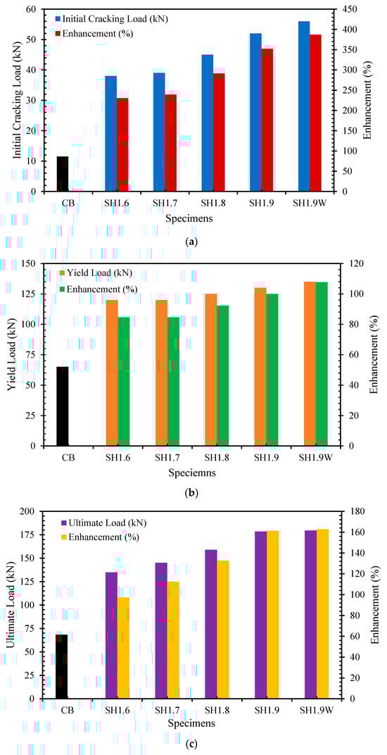
Figure 5.
Flexural capabilities of the SH strengthened specimens: (a) First cracking load; (b) Yield load; (c) Ultimate load.
The reinforced concrete specimens strengthened by a hybrid gluing method using 246.53 mm2 strengthening reinforcement as steel rebars in the NSM grooves and steel plate as an EBR at the soffit enhanced the initial cracking load up to 284% over the control specimen [47]. Strengthened RC specimens applying EBR combined with NSM technique utilizing CFRP rebars as NSM reinforcement and CFRP fabrics as an EBR reinforcement with end-anchorage increased the initial cracking load up to 220% over the control specimen [48].
The SH-CFRP technique substantially increased the yield load-bearing capabilities of RC beam specimens, as demonstrated in Figure 5b. The bonding length of CFRP rebars and plates from 1600 mm to 1900 mm of the SH strengthened specimens increased yield loads of about 85% to 108%, respectively, assessed with the unstrengthened specimen.
The specimens strengthened with the SH-CFRP system resulted in an efficient enhancement of the maximum load-bearing capability, as presented in Figure 5c. The SH technique with a 1900 mm bonded length of the strengthened reinforcement enhanced the ultimate load by about 161%, as evaluated with the unstrengthened specimen. Increasing the bonded length of the SH-CFRP strengthened reinforcement from 1600 mm to 1900 mm led to an upsurge in the maximum loads of about 97% to 161%, respectively, over the reference specimen. However, increasing the width of the S-EBR plate in the SH1.9W strengthened specimen from 50 mm to 75 mm enhanced the ultimate load to only 2% compared with the SH1.9 specimen. Hence, the increment of S-EBR plate width in the SH technique had a trivial impact on the flexural performance.
However, the soffit hybrid technique utilizing steel rebars and plate resulted in an improved ultimate load ability of up to 65% weighed with the reference specimen [47]. The NSM-CFRP bars and EBR-CFRP fabrics in the soffit hybrid method increased the ultimate load up to 169%, as judged by the unstrengthened reference beam [48].
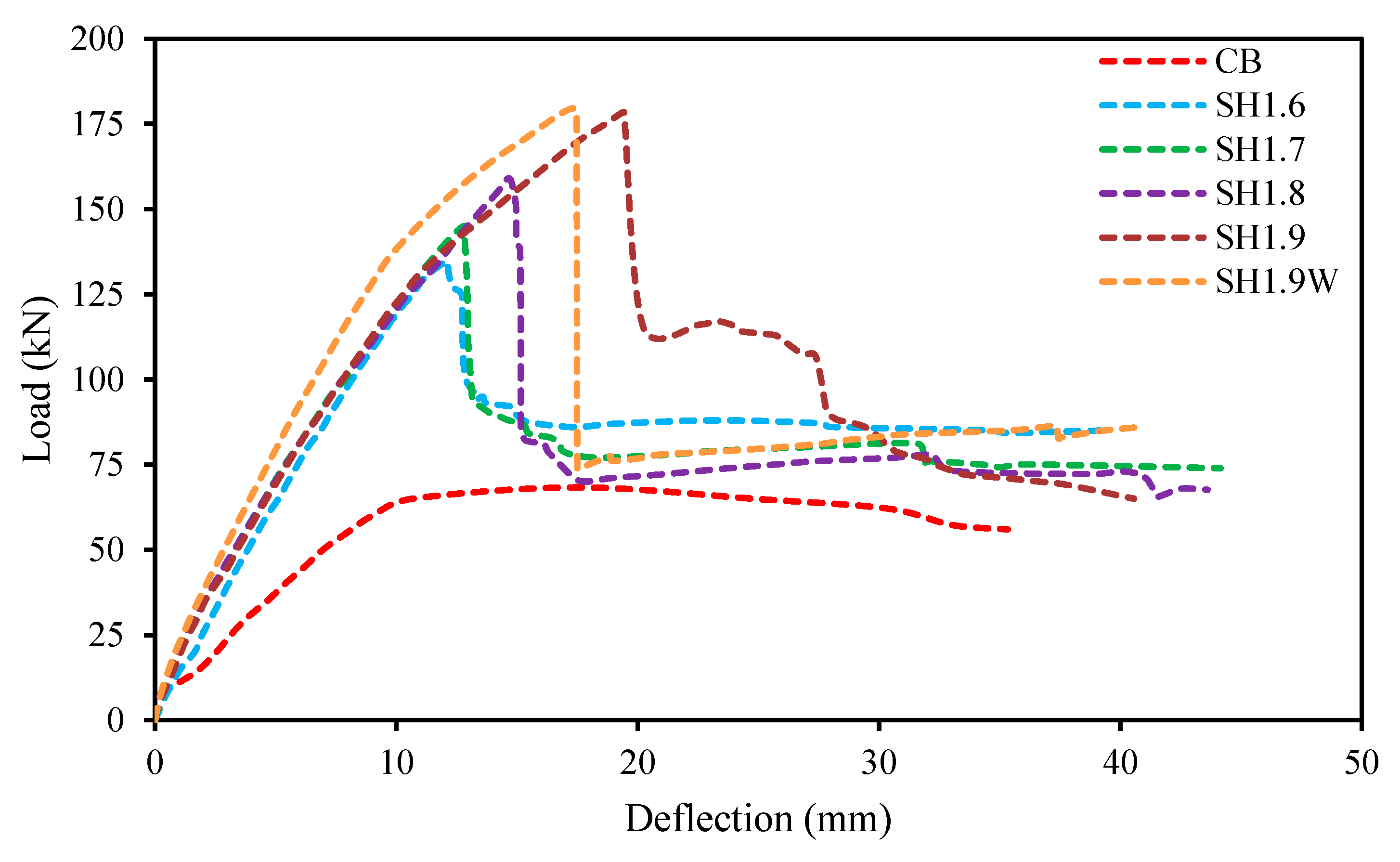
4.2. Load-Deflection Behaviour
The load-deflection correlation of the RC beam specimens strengthened with the SH technique applying CFRP (rebars and plate) are depicted in Figure 6. From the figure, it is seen that the load-deflection graphs demonstrate nearly tri-linear characteristics. The first phase of the graphs of the SH strengthened specimens varied linearly and elastic with trivial deflection up to the initiation of the first crack. The SH with CFRP bars in SNSM and plates in S-EBR significantly contributed to the enhancement of the preliminary cracking load. However, the SH strengthening reinforcement bond length did not significantly influence the deflection in this stage.
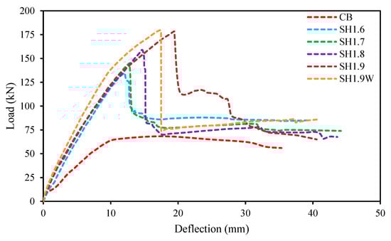
Figure 6.
Load-deflection diagram of SH strengthened specimens.
The second phase ranged from cracking in the concrete segment to yielding the major reinforcing steel of the beam specimens. The SH method with CFRP (rebars and plate) substantially intensified the stiffness of the beam specimens compared with the unstrengthened specimen. The SH-strengthened reinforcements controlled the width of the cracks and the initiation of the new cracks. Increasing the bonding length of the SH-strengthened reinforcements gradually decreased the deflection at this stage. Moreover, the deflection intensified rate was slightly higher than the previous phase.
The final phase of the load versus deflection graphs was the yielding of the internal reinforcing steel to the ultimate load of the specimen. The SH-strengthened specimens revealed better enhancement of flexural load-bearing capability and stiffness. Most of the stresses in the specimens were carried out by the strengthening reinforcement because of the yielding of the internal reinforcing steel. The bond length of SH strengthening reinforcements has significantly influenced the deflection in this stage, and increasing the width of the S-EBR plate has notably decreased the deflection. The deflection growth rate was greater than in the previous two phases, and the toughness of the specimens gradually reduced. However, the RC specimens flexural strengthened with the soffit hybrid method using steel rebars and plates were exposed to different configurations of load-deflection graphs [47].
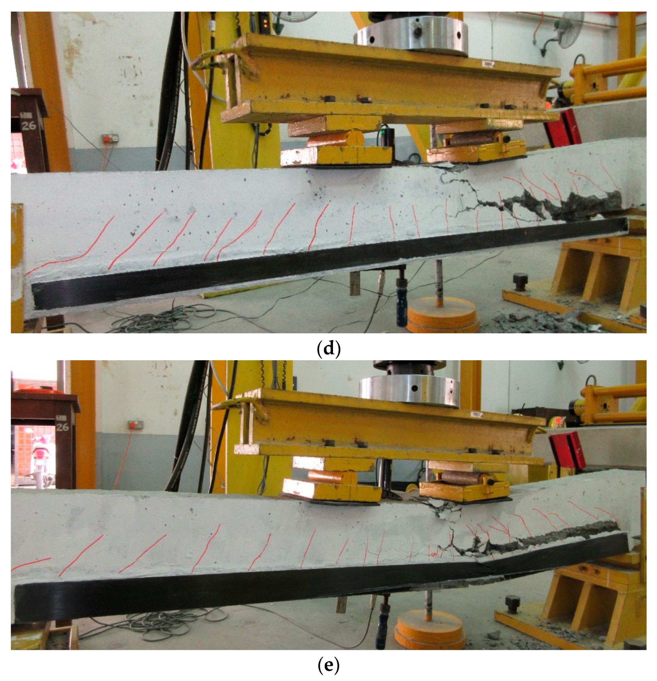
4.3. Failure Mode of the Specimens
The modes of failure for strengthened specimens with the SH technique using CFRP are illustrated in Figure 7. The failure mode of SH-CFRP-strengthened specimens occurred through concrete cover splitting. This is the most ordinary failure mode of the existing EBR and NSM methods for strengthening specimens [49,50]. An inclined crack emerged at the end of the SH-CFRP (rebars and plate), and another flexural-shear crack occurred at a certain distance from the end. Those cracks were intersecting due to high interfacial stresses, resulting in a concrete cover splitting breakdown mode visible along the level of the internal reinforcing steel.
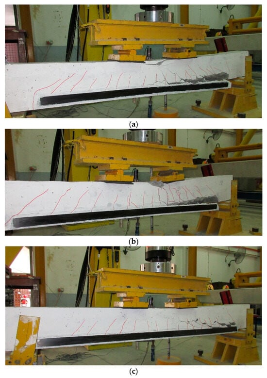

Figure 7.
Failure modes of SH and S-EBR strengthened specimens: (a) SH1.6; (b) SH1.7; (c) SH1.8; (d) SH1.9; (e) SH1.9W.
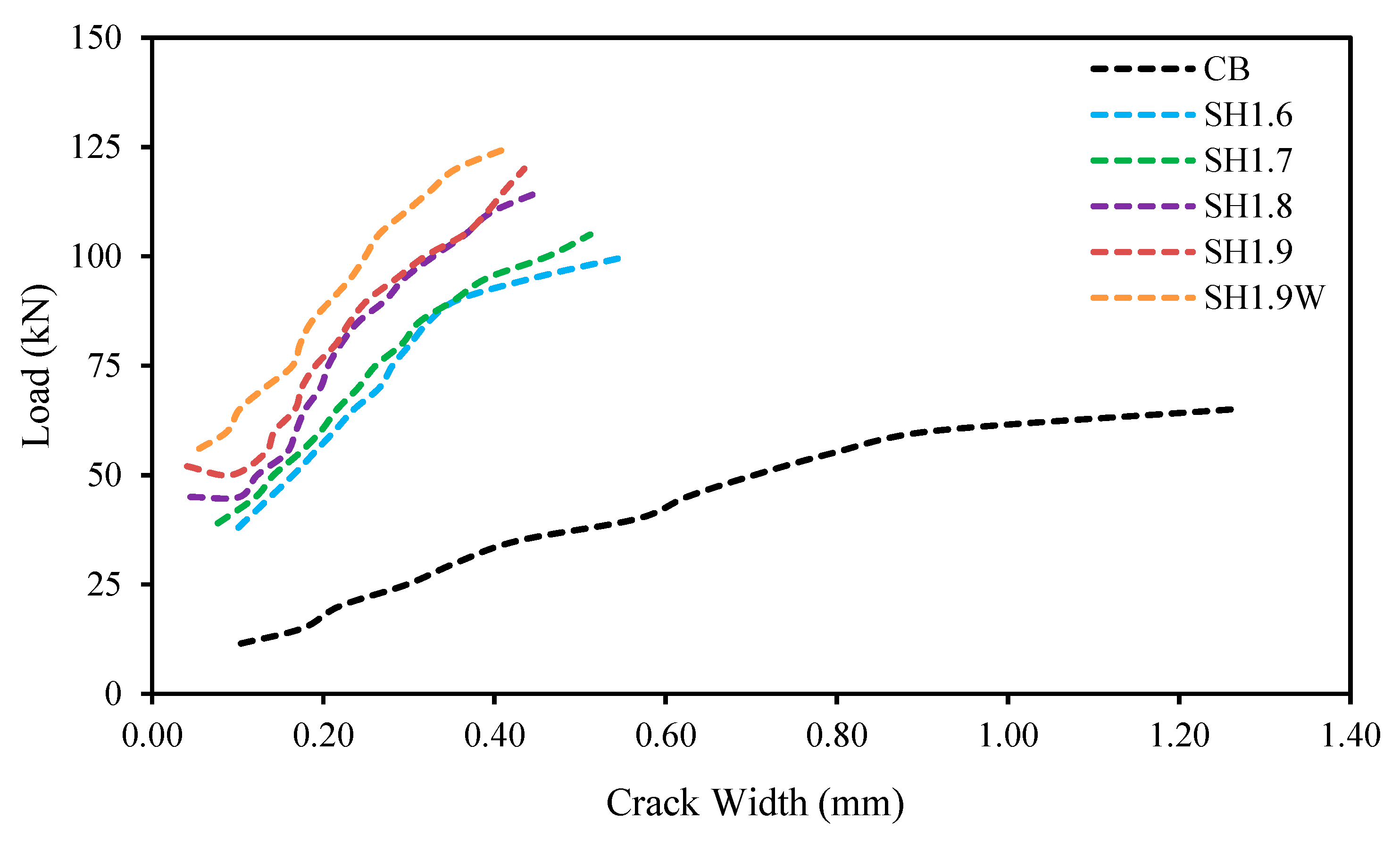
4.4. Cracking Characteristics
The functional load versus crack width of the reference unstrengthened and SH-CFRP system-strengthened beam specimens is presented in Figure 8. The crack width of the specimens was assessed by operating a Dino-Lite digital microscope in mid-span at several load levels. The development of the graphs in the SH-CFRP-strengthened specimens was steep and linear, as judged by the unstrengthened reference specimen. The crack widths considerably progressively diminished with the increase in bonded length of the SH-strengthened CFRP (rebars in SNSM and plate in S-EBR) reinforcements.
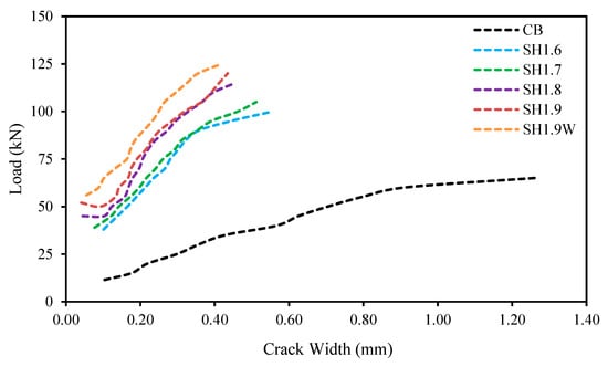
Figure 8.
Cracking characteristics of SH strengthened specimens.
Consequently, all the SH technique-strengthened beam specimens decreased the width of cracks at any load level compared with the reference specimen owing to the superior stiffness of the beams by CFRP. Therefore, the strengthening by SH-CFRP having different bond lengths or widths in the S-EBR plate had a dominant influence on increasing the number of cracks and decreasing the crack spread out throughout the specimens.
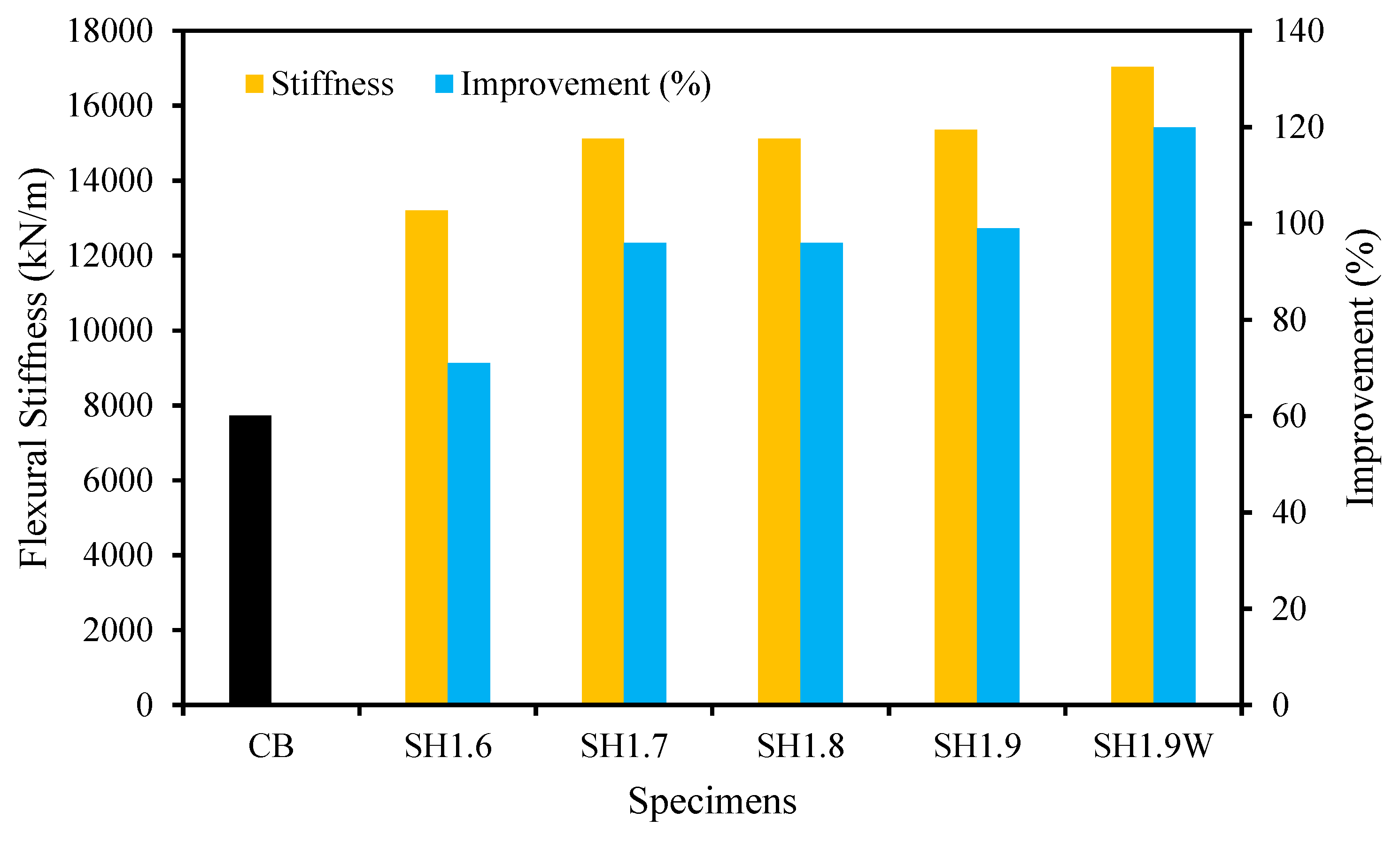
4.5. Flexural Stiffness
The flexural stiffness of the SH-CFRP having different bond length-strengthened specimens at the service load level is explicitly exhibited in Figure 9. The SH technique strengthened beam specimens, resulting in superior stiffness by CFRP compared with the unstrengthened specimen. Expanding the bonded length from 1600 mm to 1900 mm of the CFRP in SH-strengthened specimens enhanced the stiffness from 71% to 99%, respectively, over the reference beam specimen. The width of the S-EBR plate in the SH technique increased from 50 mm to 75 mm, and stiffness was enhanced from 99% to 120%, respectively, compared with the unstrengthened reference specimen. Therefore, the SH technique of varying the bond length and width of S-EBR plates in the strengthened CFRP extensively enhanced the stiffness of the specimens.

Figure 9.
Stiffness characteristics of SH strengthened specimens.
4.6. Energy Absorption Capacity
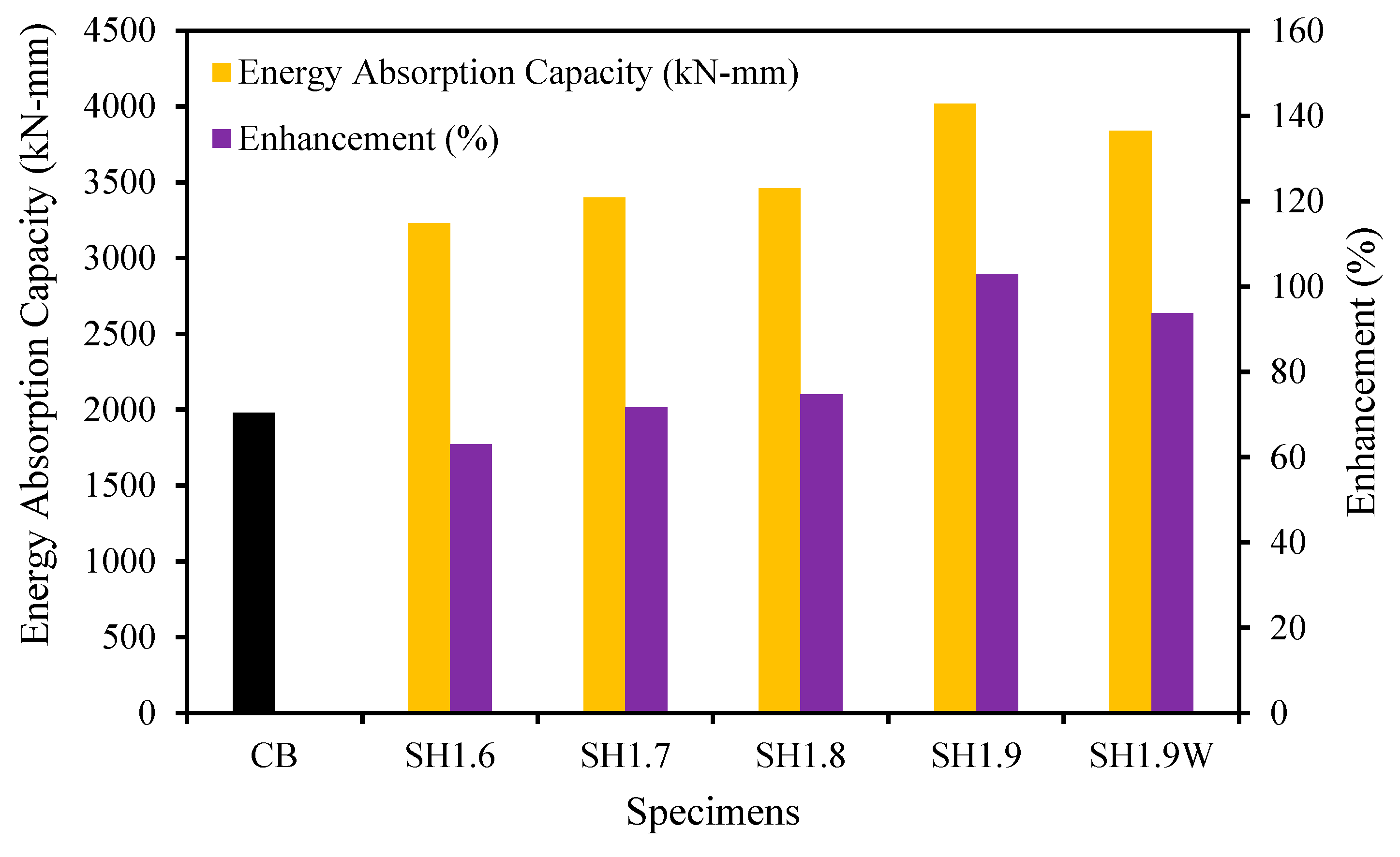
The energy absorption capacity is computed by the area of the applied load versus deflection graphs until the breakdown of the reference and the SH technique strengthens the beam specimens [51,52,53,54]. The energy absorption capacity and its enrichment for the SH-CFRP specimens are graphically exposed in Figure 10. The SH-CFRP-strengthened specimens, by escalating the bonded length from 1600 mm to 1900 mm, superior the energy absorption capability from 63% to 103%, respectively, as assessed with the control specimen. However, increasing the width of the S-EBR plate in SH-strengthened specimens reduced the energy absorption capacity owing to the acceleration of the debonding/premature failure of the specimens. Hence, the SH technique with CFRP plates having different bond lengths might be a better solution for heightening the flexural responses of RC structures, considering energy absorption capacity.
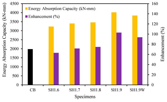
Figure 10.
The energy absorption capacity of SH strengthened specimens.
4.7. Impact of Strengthening on the Compressive Strain of Concrete
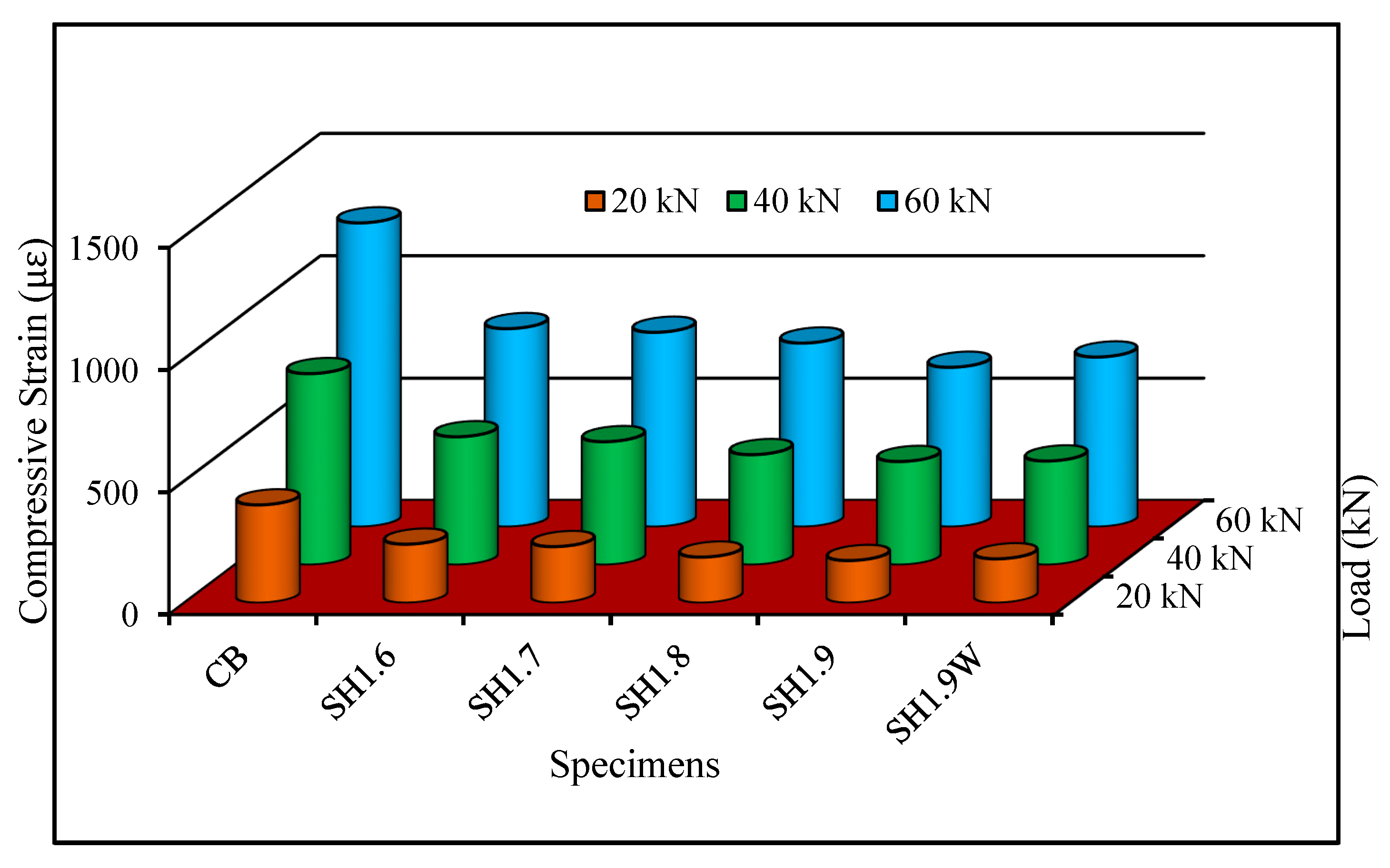
The effect of the SH technique on the concrete compressive strain at the extreme fiber of the beam samples at 20 kN, 40 kN, and 60 kN examine loads is graphically presented in Figure 11. The compressive strain progressively decreased with the increasing bond length of SH-CFRP due to the increasing load-bearing area provided by the larger bond length. The compressive strain of the SH-CFRP rods and plate-strengthened specimens decreased by 61%, 55%, and 52% at 20 kN, 40 kN, and 60 kN, respectively, assessed with the unstrengthened reference specimen. Therefore, the SH technique was more efficient than the existing strengthening technique [55,56,57].
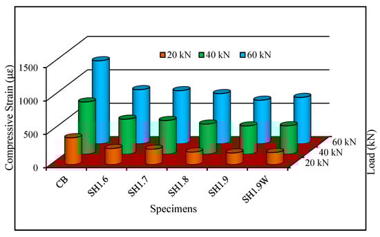
Figure 11.
Effect on the compressive strain by SH techniques.
4.8. Influence of Strengthening on the Tensile Strain of Internal Steel Rebars
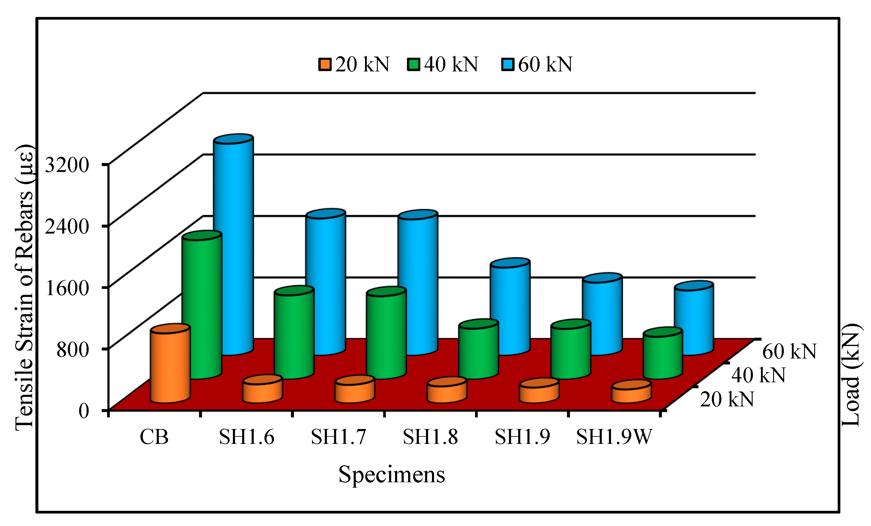
The tensile strain in the internal reinforcing steel of the SH-strengthened beam specimens at different service loads is exhibited in Figure 12. The tensile strain of reinforcing steel in the SH-CFRP rods and plate-strengthened beam specimens decreased by 81%, 71%, and 67% at 20 kN, 40 kN, and 60 kN, respectively, evaluated with the unstrengthened control specimen. Hence, the internal steel tensile strains in SH-strengthened specimens were notably diminished when assessed with the control specimen.

Figure 12.
Influence on the tensile strain of steel owing to SH strengthening technique.
4.9. Tensile Strain of the SNSM Bars in SH Technique
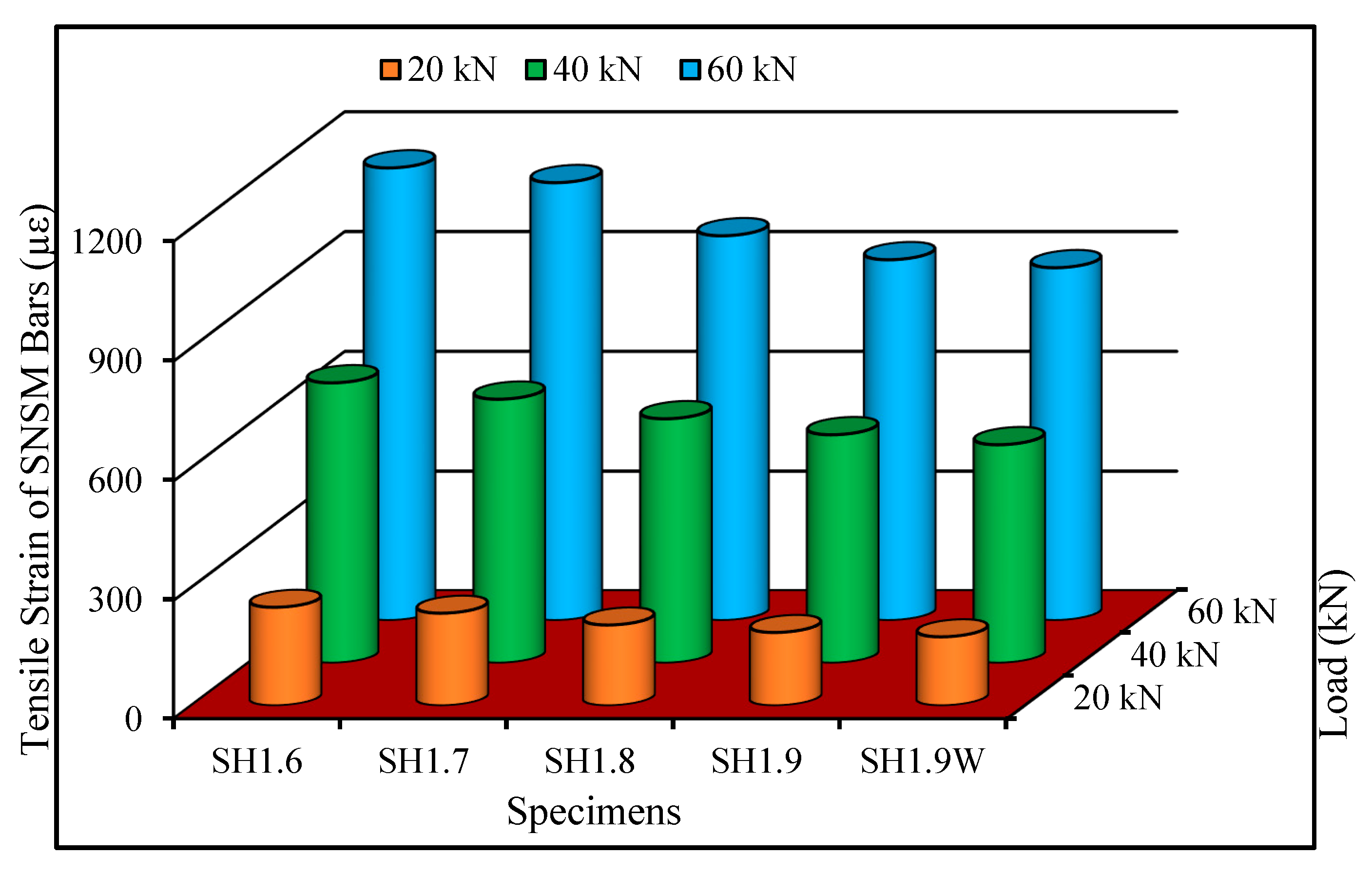
The comparison of the SNSM-CFRP rebar tensile strain in the SH-strengthened beam specimens at different service loads is presented in Figure 13. It is evident from the diagram that the tensile strain of the SNSM rebar was meaningfully diminished with increasing bond length of the strengthened beams at all loading points. However, the reducing trend of tensile strain was slightly higher in SH-CFRP with a larger width of S-EBR plate-strengthened specimens due to failure mode.

Figure 13.
The tensile strain of SNSM bars in SH strengthened specimens.
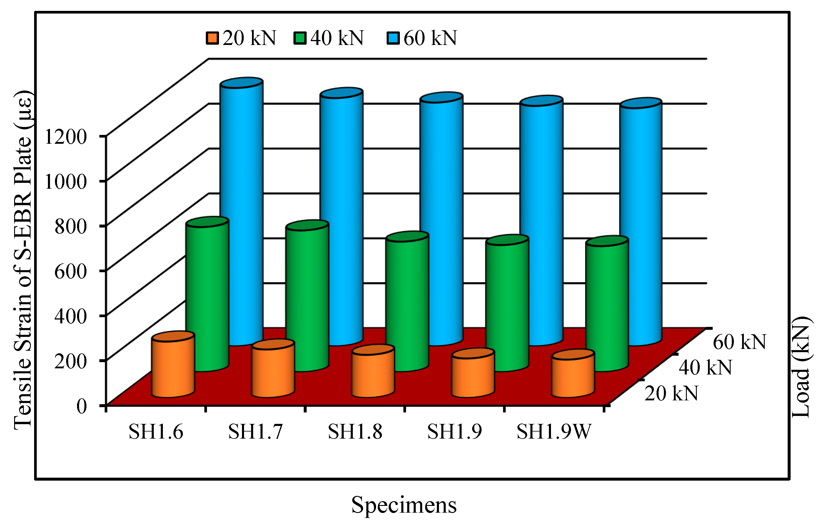
4.10. Tensile Strain of the S-EBR Plate in SH Technique
Figure 14 demonstrates the comparison of the S-EBR CFRP plate tensile strain in SH-strengthened specimens at various service load levels. Observations indicate that as the attachment length of the strengthened beam specimens increases, the tensile strain of the S-EBR plate in SH-strengthened specimens decreases across all load levels. However, the tensile strain of the wider CFRP plate in S-EBR for SH-strengthened specimens exhibits a negligible reduction trend at any load level compared to the SH-strengthened specimens.
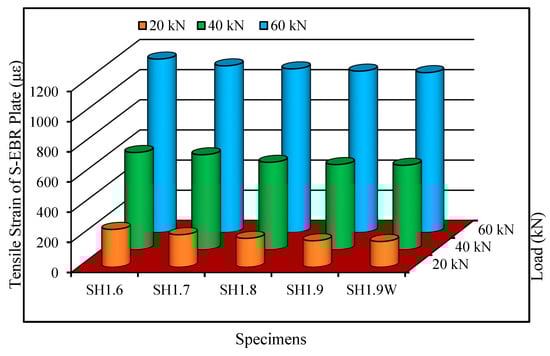
Figure 14.
The tensile strain of the S-EBR plate in SH strengthened specimens.
4.11. Impact of Bond Length
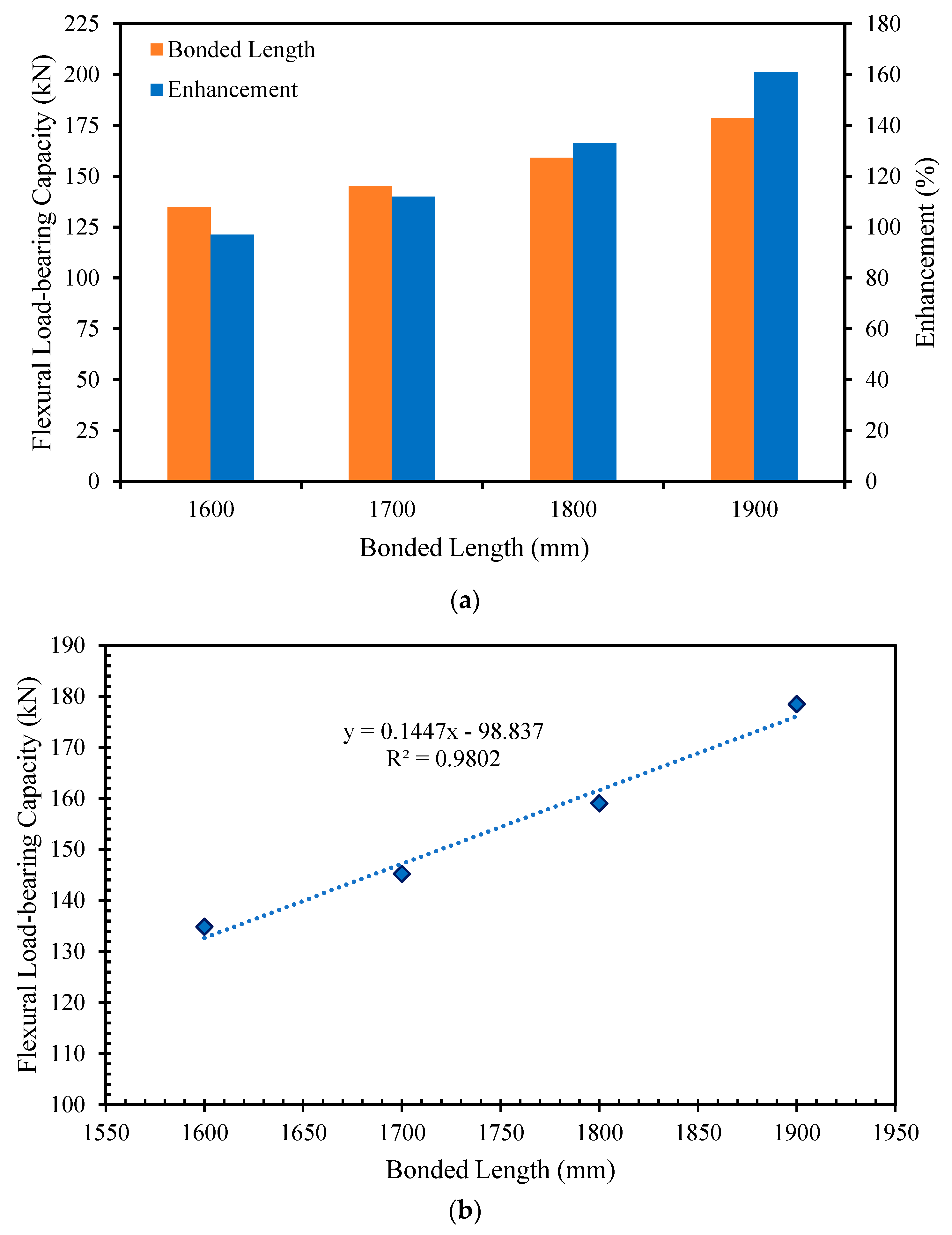
The impact of the bonded length of the SH-CFRP strengthening reinforcement on the maximum load-bearing capability is demonstrated in Figure 15a. The bonded length of the CFRP (rebars and plates) strengthening reinforcement in the SH technique increased from 1600 mm to 1900 mm, and as a result, the flexural strength improved from 97% to 161%, respectively, assessed with the control specimen. This increment in the flexural strength of the specimens depended on the surface area of the strengthening reinforcements. Increasing the bonded length of the strengthened specimens enhanced the surface area of the strengthening reinforcements, which led to the enhancement of the flexural capacity.
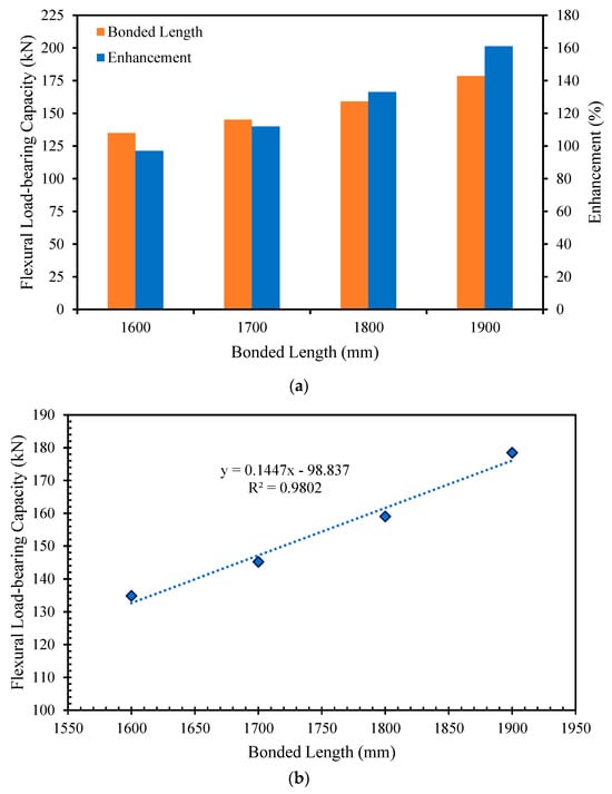
Figure 15.
Impact of SH-CFRP bonded length on the flexural strength: (a) Flexural load enhancement; (b) Correlation between the load-bearing capability and bonded length of CFRP.
A linear correlation (with strong R2) between the flexural capacity and bonded length of the CFRP (bars and plate) reinforcement in SH-strengthened beam specimens is exhibited in Figure 15b. This linear relationship could be exercised to forecast the flexural load-bearing capability of SH-CFRP-strengthened beam specimens using the exact bonded length of the strengthening reinforcement. The correlation is illustrated in the following equation:
where, PSH = flexural load-bearing capability (kN), and LSH = bonded length of the SH-CFRP strengthening reinforcement (mm).
5. Conclusions
The following conclusions have been drawn considering the experimental investigations in this study:
- ○
- Innovative SH techniques remarkably upgraded the initial cracking, yield, and ultimate load of the RC beams. Bonding length from 1600 mm to 1900 mm in the SH technique using CFRP bars and plates strengthened specimens improved initial cracking and yield loads of about 230% to 387% and 85% to 1088%, respectively, over the control beam specimen.
- ○
- Intensifying the bonded length of the strengthened reinforcement (SNSM-rebars and S-EBR-plate) from 1600 mm to 1900 mm was controlled to enhance the ultimate load-carrying capability of about 97% to 163%, respectively, assessed with the unstrengthened specimen. The proposed SH technique substantially improved the flexural responses of RC beam specimens.
- ○
- Increasing the width of the S-EBR plate in the SH (SH1.9W) strengthened specimen from 50 mm to 75 mm enhanced the ultimate load to only 2% compared with the 50 mm width of the S-EBR plate (SH1.9) specimen. Increasing the bonded length in the SH-strengthened reinforcements gradually decreased the deflection at any stage of the curves, which safeguarded the serviceability requirements.
- ○
- SH-CFRP-strengthened specimens were steep and linear compared with the control specimens due to premature failure of the strengthened beam specimens. SH-CFRP-strengthened specimens failed owing to concrete cover separation, which was followed by the crushing of extreme fiber concrete. However, it improved the failure pattern and flexural load-carrying capability.
- ○
- Extending the bonded length of the CFRP in SH-strengthened specimens from 1600 mm to 1900 mm enhanced the stiffness from 71% to 99%, respectively, evaluated with the unstrengthened reference specimen. SH-CFRP specimens, by increasing the bonded length from 1600 mm to 1900 mm, are remarkably superior in their energy absorption capability from 63% to 103%, respectively, compared with the unstrengthened specimen.
- ○
- In addition to its flexibility in increasing the strengthening reinforcement through the combination of SNSM and S-EBR techniques, the proposed SH technique is appropriate for structures facing concrete spalling, difficulty implementing existing strengthening techniques due to lack of space beneath the beam specimens, or a requirement to fulfill additional flexural capacity without harming the structures.
Author Contributions
Conceptualization, methodology, validation, formal analysis, investigation, resources, data curation, and writing—original draft preparation, M.A.H.; writing—review and editing, validation, M.I.S.; writing—review and editing, visualization, K.A.A.K.; visualization, supervision, project administration, and funding acquisition, M.Z.J., U.J.A. and N.H.R.S.; Investigation, resources, writing—review and editing, H.B.H. All authors have read and agreed to the published version of the manuscript.
Funding
This research was funded by the University of Malaya High Impact Research, grant number UM.C/HIR/MOHE/ENG/36.
Data Availability Statement
The original contributions presented in the study are included in the article, further inquiries can be directed to the corresponding authors.
Acknowledgments
The authors would like to express their gratitude for the assistance provided by the University of Malaya throughout this project. Especially thanks to the Heavy Structures Laboratories Technician.
Conflicts of Interest
The authors declare no conflicts of interest.
Correction Statement
This article has been republished with a minor correction to the reference 41. This change does not affect the scientific content of the article.
References
- Darain, K.M.; Jumaat, M.Z.; Hossain, M.A.; Hosen, M.A.; Obaydullah, M.; Huda, M.N.; Hossain, I. Automated serviceability prediction of NSM strengthened structure using a fuzzy logic expert system. Expert Syst. Appl. 2015, 42, 376–389. [Google Scholar] [CrossRef]
- Al-Huri, M.A.; Ahmad, S.; Al-Osta, M.A.; Al-Gadhib, A.H.; Kharma, K.M. Performance of corroded RC beams strengthened in flexure using UHPC: Effect of configuration and thickness of the UHPC layers. Eng. Struct. 2023, 292, 116519. [Google Scholar] [CrossRef]
- Bouzid, H.; Rabia, B.; Daouadji, T.H. Ultimate behavior of RC beams strengthened in flexure using FRP material. Eng. Struct. 2023, 289, 116300. [Google Scholar] [CrossRef]
- Hosen, M.A.; Jumaat, M.Z.; Darain, K.M.U.; Obaydullah, M.; Islam, A.S. Flexural strengthening of RC beams with NSM steel bars. In Proceedings of the International Conference on Food, Agriculture and Biology (FAB-2014), Kuala Lumpur, Malaysia, 11–12 June 2014. [Google Scholar]
- Hashemi, S.; Al-Mahaidi, R. Flexural performance of CFRP textile-retrofitted RC beams using cement-based adhesives at high temperature. Constr. Build. Mater. 2012, 28, 791–797. [Google Scholar] [CrossRef]
- Khodayari, A.; Rehmat, S.; Valikhani, A.; Azizinamini, A. Experimental Study of Reinforced Concrete T-Beam Retrofitted with Ultra-High-Performance Concrete under Cyclic and Ultimate Flexural Loading. Materials 2023, 16, 7595. [Google Scholar] [CrossRef] [PubMed]
- Obaydullah, M.; Jumaat, M.Z.; Alam, M.A.; Darain, K.M.U.; Hosen, M.A. L Shaped End Anchors to Eliminate Premature Plate End Debonding in Strengthened RC Beams. In Proceedings of the Scientific Cooperations International Workshops on Engineering Branches, University, Istanbul, Turkey, 8–9 August 2014. [Google Scholar]
- Sharaky, I.; Selmy, S.; El-Attar, M.; Sallam, H. The influence of interaction between NSM and internal reinforcements on the structural behavior of upgrading RC beams. Compos. Struct. 2020, 234, 111751. [Google Scholar] [CrossRef]
- Barris, C.; Sala, P.; Gómez, J.; Torres, L. Flexural behaviour of FRP reinforced concrete beams strengthened with NSM CFRP strips. Compos. Struct. 2020, 241, 112059. [Google Scholar] [CrossRef]
- Hosen, M.A.; Jumaat, M.Z.; Alengaram, U.J.; Islam, A.; Bin Hashim, H. Near surface mounted composites for flexural strengthening of reinforced concrete beams. Polymers 2016, 8, 67. [Google Scholar] [CrossRef]
- Rahman, M.M.; Jumat, M.Z.; Hosen, M.A.; Islam, A.S. Effect of adhesive replacement with cement mortar on NSM strengthened RC Beam. Rev. Construcción J. Constr. 2016, 15, 61–72. [Google Scholar] [CrossRef]
- Franco, N.; Chastre, C.; Biscaia, H. Strengthening RC beams using stainless steel continuous reinforcement embedded at ends. J. Struct. Eng. 2020, 146, 04020065. [Google Scholar] [CrossRef]
- Barros, J.A.; Fortes, A. Flexural strengthening of concrete beams with CFRP laminates bonded into slits. Cem. Concr. Compos. 2005, 27, 471–480. [Google Scholar] [CrossRef]
- Obaydullah, M.; Jumaat, M.Z.; Alengaram, U.J.; ud Darain, K.M.; Huda, M.N.; Hosen, M.A. Prestressing of NSM steel strands to enhance the structural performance of prestressed concrete beams. Constr. Build. Mater. 2016, 129, 289–301. [Google Scholar] [CrossRef]
- Hosen, M.A.; Al Kaaf, K.A.; Islam, A.S.; Jumaat, M.Z.; Kazmi, Z.A. Behavior and modeling of RC beams strengthened with NSM-steel technique. Struct. Eng. Mech. 2023, 88, 67–81. [Google Scholar]
- Aram, M.R.; Czaderski, C.; Motavalli, M. Debonding failure modes of flexural FRP-strengthened RC beams. Compos. Part B Eng. 2008, 39, 826–841. [Google Scholar] [CrossRef]
- Li, G.; Zhang, A.; Jin, W. Effect of shear resistance on flexural debonding load-carrying capacity of RC beams strengthened with externally bonded FRP composites. Polymers 2014, 6, 1366–1380. [Google Scholar] [CrossRef]
- Al-Zu’bi, M.; Fan, M.; Anguilano, L. Near-surface mounted-FRP flexural retrofitting of concrete members using nanomaterial-modified epoxy adhesives. J. Build. Eng. 2024, 84, 108549. [Google Scholar] [CrossRef]
- Aljidda, O.; Alnahhal, W.; El Refai, A. Flexural strengthening of one-way reinforced concrete slabs using near surface-mounted BFRP bars. Eng. Struct. 2024, 303, 117507. [Google Scholar] [CrossRef]
- Shayanfar, M.A.; Ghanooni-Bagha, M.; Afzali, S. Reinforced concrete columns strengthened with near-surface mounted and hybrid FRP under compression with or without eccentricity: Experimental study and finite element modeling. Case Stud. Constr. Mater. 2024, 20, e02761. [Google Scholar] [CrossRef]
- Abed, M.A.; Alkurdi, Z.; Fořt, J.; Černý, R.; Solyom, S. Bond behavior of FRP bars in lightweight SCC under direct pull-out conditions: Experimental and numerical investigation. Materials 2022, 15, 3555. [Google Scholar] [CrossRef]
- Wang, H.-P.; Ni, Y.-Q.; Dai, J.-G.; Yuan, M.-D. Interfacial debonding detection of strengthened steel structures by using smart CFRP-FBG composites. Smart Mater. Struct. 2019, 28, 115001. [Google Scholar] [CrossRef]
- Capozucca, R. Static and dynamic response of damaged RC beams strengthened with NSM CFRP rods. Compos. Struct. 2009, 91, 237–248. [Google Scholar] [CrossRef]
- Sharaky, I.A.; Torres, L.; Sallam, H. Experimental and analytical investigation into the flexural performance of RC beams with partially and fully bonded NSM FRP bars/strips. Compos. Struct. 2015, 122, 113–126. [Google Scholar] [CrossRef]
- Coelho, M.R.; Sena-Cruz, J.M.; Neves, L.A. A review on the bond behavior of FRP NSM systems in concrete. Constr. Build. Mater. 2015, 93, 1157–1169. [Google Scholar] [CrossRef]
- Zhang, S.S.; Yu, T.; Chen, G. Reinforced concrete beams strengthened in flexure with near-surface mounted (NSM) CFRP strips: Current status and research needs. Compos. Part B Eng. 2017, 131, 30–42. [Google Scholar] [CrossRef]
- Wang, X.; Cheng, L. Bond characteristics and modeling of near-surface mounted CFRP in concrete. Compos. Struct. 2021, 255, 113011. [Google Scholar] [CrossRef]
- Sharaky, I.A.; Torres, L.; Comas, J.; Barris, C. Flexural response of reinforced concrete (RC) beams strengthened with near surface mounted (NSM) fibre reinforced polymer (FRP) bars. Compos. Struct. 2014, 109, 8–22. [Google Scholar] [CrossRef]
- Al-Mahmoud, F.; Castel, A.; François, R.; Tourneur, C. Strengthening of RC members with near-surface mounted CFRP rods. Compos. Struct. 2009, 91, 138–147. [Google Scholar] [CrossRef]
- Tang, W.; Balendran, R.; Nadeem, A.; Leung, H. Flexural strengthening of reinforced lightweight polystyrene aggregate concrete beams with near-surface mounted GFRP bars. Build. Environ. 2006, 41, 1381–1393. [Google Scholar] [CrossRef]
- Bilotta, A.; Ceroni, F.; Nigro, E.; Pecce, M. Efficiency of CFRP NSM strips and EBR plates for flexural strengthening of RC beams and loading pattern influence. Compos. Struct. 2015, 124, 163–175. [Google Scholar] [CrossRef]
- Hosen, M.A.; Jumaat, M.Z.; Islam, A.S. Side Near Surface Mounted (SNSM) technique for flexural enhancement of RC beams. Mater. Des. 2015, 83, 587–597. [Google Scholar] [CrossRef]
- Hosen, M.A.; Jumaat, M.Z.; Alengaram, U.J.; Sulong, N.R.; Islam, A.S. Structural performance of lightweight concrete beams strengthened with side-externally bonded reinforcement (S-EBR) technique using CFRP fabrics. Compos. Part B Eng. 2019, 176, 107323. [Google Scholar] [CrossRef]
- Raza, S.; Khan, M.K.; Menegon, S.J.; Tsang, H.-H.; Wilson, J.L. Strengthening and repair of reinforced concrete columns by jacketing: State-of-the-art review. Sustainability 2019, 11, 3208. [Google Scholar] [CrossRef]
- Gino, D.; Anerdi, C.; Castaldo, P.; Ferrara, M.; Bertagnoli, G.; Giordano, L. Seismic upgrading of existing reinforced concrete buildings using friction pendulum devices: A probabilistic evaluation. Appl. Sci. 2020, 10, 8980. [Google Scholar] [CrossRef]
- Frangopol, D.M.; Liu, M. Maintenance and management of civil infrastructure based on condition, safety, optimization, and life-cycle cost. In Structures and Infrastructure Systems; Routledge: London, UK, 2019; pp. 96–108. [Google Scholar]
- Lomba-Fernández, C.; Hernantes, J.; Labaka, L. Guide for climate-resilient cities: An urban critical infrastructures approach. Sustainability 2019, 11, 4727. [Google Scholar] [CrossRef]
- Hosen, M.A.; Jumaat, M.Z.; Alengaram, U.J.; Sulong, N.R. CFRP strips for enhancing flexural performance of RC beams by SNSM strengthening technique. Constr. Build. Mater. 2018, 165, 28–44. [Google Scholar] [CrossRef]
- Hosen, M.A.; Jumaat, M.Z.; Saiful Islam, A.; Obaydullah, M.; Darain, M.; Huda, N. Investigation on energy absorption capacity of reinforced concrete beams by the near-surface mounted technique using ductile materials. Sci. Adv. Mater. 2016, 8, 1536–1546. [Google Scholar] [CrossRef]
- Composite, H.A. Product Data Sheet-CFRP Rebar Properties. Available online: https://www.anjiezj.com/carbon-fiber-rebar (accessed on 19 April 2024).
- Sika. SikaCarbodur®-E1012, Product Data Sheet, Carbon Fibre Plate for Structural Strengthening. Available online: https://gbr.sika.com/en/construction/structural-strengthening/column-beams-strengthening/carbon-fibre-plates/sika-carbodur-e.html (accessed on 19 April 2024).
- Data, S.P. Sikadur-30: Two-Part Epoxy Adhesive for Bonding Reinforcement. Available online: https://usa.sika.com/en/construction/repair-protection/structural-strengthening/epoxies/sikadur-30.html (accessed on 19 April 2024).
- Hosen, M.A.; Jumaat, M.Z.; Islam, A.; Darain, K.; Rahman, M. Flexural performance of reinforced concrete beams strengthened by a new side near-surface mounted technique using carbon fibre-reinforced polymer bars: Experimental and analytical investigation. Sci. Adv. Mater. 2016, 8, 726–740. [Google Scholar] [CrossRef]
- Lv, J.; Lin, D.; Fu, B.; Liu, S.; Han, Z. Flexural performance of reinforced concrete beams strengthened using near-surface-mounted carbon-fiber-reinforced polymer bars: Effects of bonding patterns. Compos. Struct. 2024, 335, 117985. [Google Scholar] [CrossRef]
- Sabzi, J.; Esfahani, M.R.; Ramezani, A.; Ozbakkaloglu, T. A comparison between the behavior of beams strengthened by FRP sheets and FRCM composites. Eng. Struct. 2024, 306, 117796. [Google Scholar] [CrossRef]
- Armonico, A.; Michel, L.; Saidi, M.; Ferrier, E. Experimental Study on the Effect of Steel Reinforcement Ration on the Cracking Behaviour of FRP-Strengthened RC Elements. Buildings 2024, 14, 950. [Google Scholar] [CrossRef]
- Rahman, M.M.; Jumaat, M.Z.; Rahman, M.A.; Qeshta, I.M. Innovative hybrid bonding method for strengthening reinforced concrete beam in flexure. Constr. Build. Mater. 2015, 79, 370–378. [Google Scholar] [CrossRef]
- Darain, K.M.; Jumaat, M.Z.; Shukri, A.A.; Obaydullah, M.; Huda, M.N.; Hosen, M.A.; Hoque, N. Strengthening of RC beams using externally bonded reinforcement combined with near-surface mounted technique. Polymers 2016, 8, 261. [Google Scholar] [CrossRef]
- Hosseinnia, A.; Kabir, M.Z. Evaluation of ultimate strength and damage progress of strengthening RC beams using NSM technique under low-velocity impact loading. Compos. Part C Open Access 2024, 13, 100438. [Google Scholar] [CrossRef]
- Gong, S.; Su, M.; Yoshitake, I.; Zhu, C.; Peng, H. Factors affecting flexural properties of RC beams strengthened with gradually prestressed NSM CFRP strips. Eng. Struct. 2024, 306, 117865. [Google Scholar] [CrossRef]
- Hosen, M.A.; Alengaram, U.J.; Jumaat, M.Z.; Sulong, N.; Darain, K. Glass Fiber Reinforced Polymer (GFRP) bars for enhancing the flexural performance of RC beams using side-NSM technique. Polymers 2017, 9, 180. [Google Scholar] [CrossRef]
- Hosen, M.A.; Jumaat, M.; Alsubari, B.; Sulong, N.R.; Ibrahim, Z.; Alengaram, U.J.; Hashim, H. Effect of bonding materials on the flexural improvement in RC beams strengthened with SNSM technique using GFRP bars. J. Build. Eng. 2020, 32, 101777. [Google Scholar] [CrossRef]
- Hosen, M.A.; Althoey, F.; Jumaat, M.Z.; Alengaram, U.J.; Sulong, N.R. Flexural performance of RC beams strengthened with externally-side bonded reinforcement (E-SBR) technique using CFRP composites. Materials 2021, 14, 2809. [Google Scholar] [CrossRef]
- Hosen, M.A.; Jumaat, M.Z.; Islam, A.; Salam, M.A.; Mo, K.H. Side-NSM composite technique for flexural strengthening of RC beams. Comput. Concr. 2017, 20, 439–448. [Google Scholar]
- Hosen, M.A.; Jumaat, M.Z.; Islam, A.; Kamruzzaman, M.; Huda, M.N.; Soeb, M.R. Eliminating concrete cover separation of NSM strengthened beams by CFRP end anchorage. Struct. Eng. Mech. 2015, 56, 899–916. [Google Scholar] [CrossRef]
- Hosen, M.A.; Jumaat, M.Z.; Islam, A.S.; Al Kaaf, K.A.; Shammas, M.I.; Hakeem, I.Y.; Islam, M.M.U. Potential side-NSM strengthening approach to enhance the flexural performance of RC beams: Experimental, numerical and analytical investigations. Struct. Eng. Mech. 2023, 85, 179. [Google Scholar]
- Jung, W.-T.; Park, Y.-H.; Park, J.-S.; Kang, J.-Y.; You, Y.-J. Experimental investigation on flexural behavior of RC beams strengthened by NSM CFRP reinforcements. Spec. Publ. 2005, 230, 795–806. [Google Scholar]


Disclaimer/Publisher’s Note: The statements, opinions and data contained in all publications are solely those of the individual author(s) and contributor(s) and not of MDPI and/or the editor(s). MDPI and/or the editor(s) disclaim responsibility for any injury to people or property resulting from any ideas, methods, instructions or products referred to in the content. |
© 2024 by the authors. Licensee MDPI, Basel, Switzerland. This article is an open access article distributed under the terms and conditions of the Creative Commons Attribution (CC BY) license (https://creativecommons.org/licenses/by/4.0/).