Article

Estimating the Single Shear Strength Performance of Joints Using Screws and Nails with Decayed Wood

1
Architecture Program, Graduate School of Advanced Science and Engineering, Hiroshima University, Kagamiyama 1-4-1, Higashihiroshima 739-8527, Japan
2
Division of Civil Engineering and Architecture, Faculty of Advanced Science and Technology, Kumamoto University, 2-39-1 Kurokami, Kumamoto 860-8555, Japan
3
Architecture Program, Department of Science and Technology, Faculty of Science and Technology, Oita University, Dannoharu 700, Oita 870-1192, Japan
*
Author to whom correspondence should be addressed.
Buildings 2024, 14(7), 1924; https://doi.org/10.3390/buildings14071924
Submission received: 19 May 2024 / Revised: 14 June 2024 / Accepted: 21 June 2024 / Published: 24 June 2024
(This article belongs to the Special Issue Contemporary Applications of Wood in Architecture and Construction)

Abstract

:
To enable the long-term use of existing wooden structures, appropriately evaluating the extent of damage of the biodeterioration of structural performance, including members and joint systems, is necessary. To give one example, accurately estimating the single shear strength performance of nail and screw joints with decay is crucial. Therefore, this study proposes a method to model this by dividing wood into multiple layers with different strength performance, considering the grade of deterioration in a cross-section of decayed wood. The model was used to differentiate the sound layer and three decayed layers (multilayer) according to the extent of the damage. The estimated values, which were produced using the proposed model, were compared to the single shear strength of screw and nail joints with decay using two species of wood, namely Abies sachalinensis (Todomatsu) and Cryptomeria japonica (Sugi). The results point to a good fit between the average value of the experimental results and the estimated values of the proposed model. Compared with the existing (single-layer) model, the proposed model improved the accuracy of estimating the strength of wood undergoing early deterioration and therefore was considered usable.

1. Introduction

To reduce environmental burden and conserve resources, the importance of long-term use of wooden houses is increasingly attracting scholarly attention. Research results on the durability of structural members and joints, such as the effects of moisture content and rust, have also been reported [1,2,3]. One of the factors that reduces the seismic performance of wooden houses is biodeterioration, such as termite feeding damage and decay. In particular, biodeterioration can rapidly degrade seismic performance. Among the causes of wood deterioration, decay caused by brown rot fungi significantly degrades wood members. For example, most indoor structural damage in North American buildings is caused by brown rot fungi [4], and it is estimated that about 80% of decay is caused by brown rot fungi [5]. Moisture intrusion, which is necessary to promote decay, has also been reported to affect the shear performance of wood joints [6]. Typically, a moisture-proof treatment or preservative-treated material is used for constructing a wooden house to ensure durability. However, the possibility exists that existing houses lack treatment with consideration of durability or that biodeterioration has occurred. In fact, studies that investigated the deterioration conditions of structural members also reported cases of decay in wooden houses [7]. In addition, a survey conducted after a major earthquake reported cases of collapsed wooden houses with significant biodeterioration [8]. It has been pointed out that wooden houses may be unable to exhibit the seismic performance expected from their original design during major earthquakes due to such biodeterioration. To enable the long-term use of existing wooden structures, appropriately evaluating the residual strength of structural members and joints damaged by biodeterioration is necessary. This is because the amount of reinforcement required depends on the residual performance of the wood and the degree of deterioration. In construction using wooden materials, mechanical joints are frequently used to combine members, which significantly influence seismic performance. If the performance of the joint deteriorates, then the seismic performance of the building is assumed to deteriorate. Therefore, elucidating the degree of deterioration in the performance of mechanical joints of wooden structures due to biodeterioration is necessary. Evaluating the degree of decay is crucial to evaluation of the performance of decayed members and mechanical joints. For example, Wilcox [9] provided a comprehensive report on the effects of decay on various strengths of wood.
Currently, in seismic diagnosis in Japan, a screwdriver is thrust into a piece of wood, and the degree of deterioration is diagnosed by the degree of penetration. Such methods are not quantitative because they require inspectors for a subjective evaluation of the degree of decay. It is especially difficult to determine the degree of deterioration of wood in the early stages of deterioration, when it is thought to have retained its strength. On the other hand, research is underway on methods to evaluate the density or degree of deterioration of wood [10,11]. In this research, the Pilodyn® was focused on as one of the deterioration diagnosis devices. The Pilodyn is a device that determines the degree of deterioration by driving a steel pin with a fixed amount of energy into a wood piece and measuring the depth of the pin. Although this has the disadvantages of requiring destruction of a small part of the finish for diagnosis and measuring only the surface of the material, it is capable of quantitative diagnosis that does not depend on the inspector. There are reports that the density of wood can be estimated based on the driving depth measured with a Pilodyn [12]. In addition, there are previous studies that have attempted to use the measured value of the Pilodyn to diagnose wood deterioration. The results have demonstrated a correlation between the driving depth indicated by the Pilodyn and the mass loss rate of wood [13]. In addition, previous studies examined the relationship between the residual strength of joints and the degree of deterioration based on the measurement values of equipment for diagnosing biodeterioration, such as the Pilodyn, to evaluate the actual situation based on surveys of existing houses. For example, Takanashi et al. examined the withdrawal strength of nailed joints with decay and nail corrosion [14]. The authors reported that slight corrosion of the nails increased the withdrawal strength. In turn, the withdrawal strength, which excludes corrosion effects, pointed to a negative correlation with the Pilodyn driving depth. Alternatively, Sawata et al. investigated the effect of decay on various shear performances of dowel-type joints [15]. The results indicated significant decreases in the initial stiffness, yield load, and maximum load of dowel-type joints with decay along with small mass losses of wood. Regarding the shear performance of joints using nails and screws, Kent et al. investigated the effects of decay on nailed joints using oriented strand board (OSB) as side materials [16,17]. The study elucidated that the shear performance of joints can be evaluated using the degree of decay and density of the OSB. Sawata and Sasaki conducted a shear test of nailed joints while using decayed Todomatsu lumber as the main and side materials [18], whereas Ueda et al. investigated the degradation of screwed joints with decayed wood [19]. If the driving depth of the Pilodyn is small (16–23.5 mm), then no significant relationship exists between the driving depth and the deterioration ratio of the strength characteristics. The authors reported that the shear performance of screwed joints with multiple screws can be estimated using the result of a single screw by multiplying the properties, despite the decay of the main members.
Data have been accumulated as a tool for evaluating the degree of biodeterioration. For example, Nishino et al. organized experimental data and constructed a database [20]. By using this database, it is possible to evaluate the strength characteristic values of various joints and types of wood with biodeterioration with the measured values in the future. However, covering all species and joint methods is difficult. In other words, a method for estimating the residual performance of joints based on the measurement results of equipment for diagnosing biodeterioration is required. Therefore, several models were proposed for estimating the strength of joints using wood damaged by biodeterioration. In terms of termite damage to wood near a joint, a two-layer model (termite damage model) was proposed in which members are divided into two parts, namely a damaged part (where strength is lost) and a sound part (Figure 1a) [21]. In the case of the decay of wood near a joint, members are assumed to be uniformly decayed, and a single-layer model which reduces the bearing strength of the entire part (Figure 1b) has been proposed [22]. In practice, because decay progresses in stages, the degree of decay is not identical at the surface, the starting point of decay, and at the deep part of a piece of wood. The density decreases with the proximity to the location of decay, and the deeper the depth from the surface, the smaller the rate of decrease in density. This tendency is the same as that reported by Maeda et al. [23]. In other words, the residual strength is underestimated, especially in the case of decayed wood with minimal damage. This aspect becomes a problem, because lightly damaged wood may continue to be used.
The purpose of this study was to improve the accuracy of estimating the yield strength of screw joints with decay. This study proposes the degradation layer model (Figure 1c), which illustrates that decay differs according to the direction of the depth. This is a method of modeling which divides wood into multiple layers with different strength performance values, considering the gradation of deterioration in cross-sections of decayed wood. In addition, the model was used to estimate the yield shear strength and compare it with experimental data.
Differences in the strength performance of wood, corresponding to the distribution in the degree of deterioration in the depth direction, can be taken into account in the evaluation of the performance of nail or screw joints. By improving the accuracy of estimating joint performance in the early stages of deterioration, it will be possible to continue using deteriorated members according to their degree of deterioration, rather than uniformly replacing them. Furthermore, by being able to take into account differences in the degree of deterioration in wood cross-sections, it will be possible to evaluate differences in reinforcement effects according to the lengths of nails when adding more nails during seismic retrofitting. In the future, this will lead to proposals for appropriate reinforcement methods based on the degree of decay at the joints.

2. Calculation Methods

2.1. Overview of the Proposed Model and Calculation Method of the Yield Strength

This study proposes a new model for calculating the single shear yield strength of a screw joint. It considers the difference in bearing strength in the depth direction of a cross-section caused by progressing decay (degradation layer model; Figure 1c). In this model, the wood is modeled into several layers, such as a sound layer and multiple decayed layers, according to the degree of decay. Multiple decayed layers pertain to layers which have been damaged by decay, where their density and strength are assumed to decrease with the increase in the level of decay. Conversely, the sound layer pertains to a layer with little decay progress and can be regarded as undamaged material. Note that this study targets a situation in which decay begins on the surface of wood (crossbeams and columns) which has a high moisture content due to water leakage or other causes. Therefore, starting from the decay initiation point (in this case, the top surface), the cross-section of wood is modeled in the order of the sound layer and decayed layers.
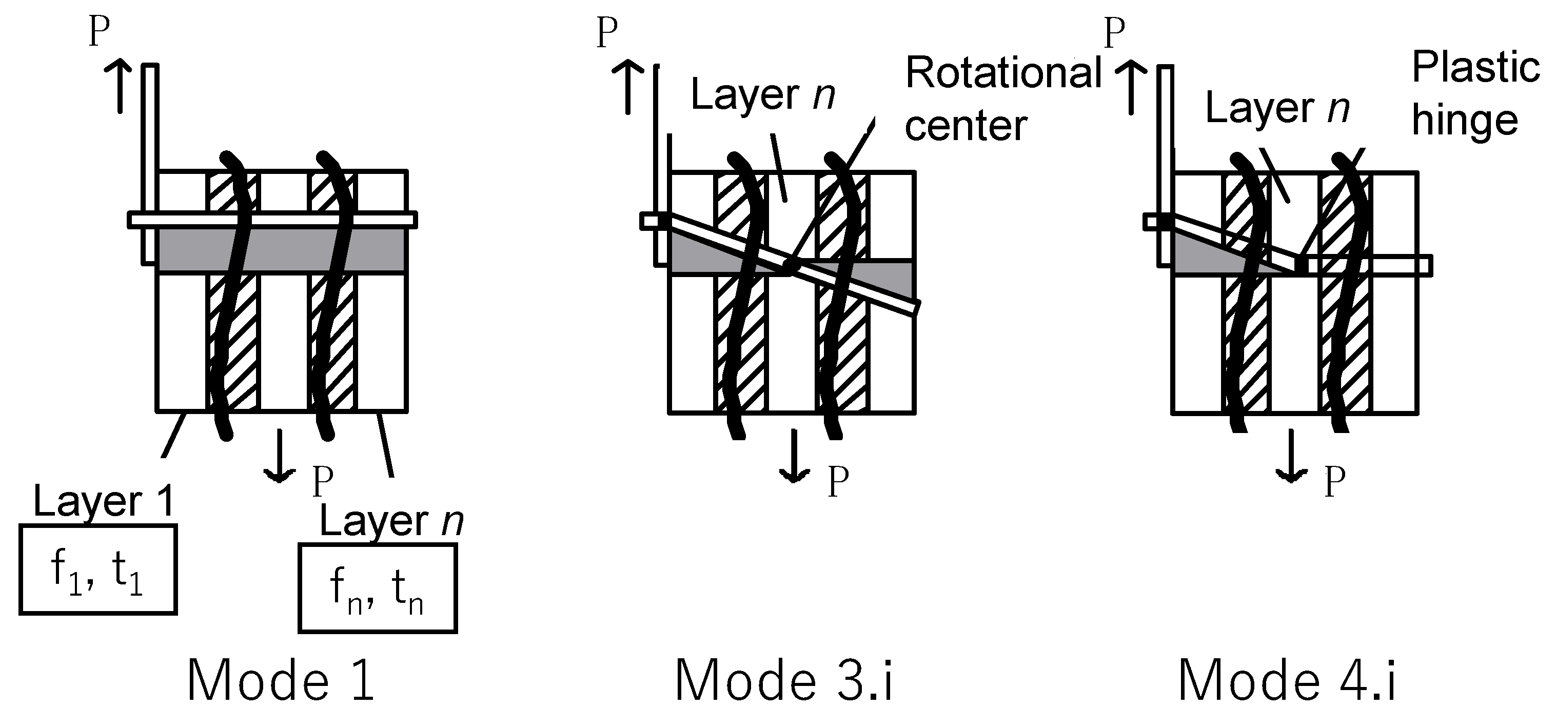
The shear strength of joints with decayed wood is calculated by applying the degradation layer model proposed in this study to existing formulas. Tomitaka and Toda proposed a formula for applying laminated materials with different physical properties to European yield theory, which assumes the use of cross-laminated timber (CLT) (Equations (1)–(7)) [24]. Here, n denotes the number of layers determined by the decay level and length of a connector, while i is a layer which includes the rotational center of the connector or the position of a plastic hinge. For each mode which follows (Figure 2), the unknown value i is calculated from 1 to n, where the minimum value is considered the yield strength.
Mode 1 is expressed as
P y   =   d × j   =   1 n f j   ×   t j
Meanwhile Mode 3.i is
P y   =   2 f i   ×   x   ×   d   +   d   ×   j   =   1 i     1 f j   ×   t j d   × j   =   i n f j   ×   t j
x   =   j   =   1   i     1 t j + j   =   1 i     1 t j 2 1 f i S 1 S i 1 d × M y
and Mode 4.i is as follows:
P y   =   f i   ×   x   × d   + d   × j   =   1 i     1 f j   ×   t j
x   =   j   =   1 i     1 t j + j   =   1 i     1 t j 2 2 f i S 1 2 d × M y
S 1   =   k   =   1 i     1 f k   ×   t k 1 2   ×   t k + j     =   1 k t j 1
S i   =   k   =   i n f k   ×   t k 1 2   ×   t k + j     =   1 k t j 1
However, 0 <   x   <   t i . In the above equations, t j is the thickness of the layer j (in millimeters), t 0 = 0 , f j is the bearing strength of the layer j (in N/mm2), x is the rotational center or plastic hinge of the connector (in millimeters), l is the effective thickness of the main member (or effective length of the connector), and My is the fully plastic bending moment of the connector (in N/mm). We also have
M y   =   F d   3 / 6
where F is the material strength of the connector (in N/mm2) and d is the effective diameter of the connector (in millimeters).
Here, the thickness tn of the nth layer changes depending on the length of the connector. Thus, Equation (9) can be used to obtain its value:
t n   =   l j   =   1 n     1 t n
To determine the shear strength of a joint with decayed wood using the above equation, the thickness and bearing strength of each layer are needed. The bearing strength of each level of decay can be obtained from existing research. Therefore, in the next section, we propose a modeling method (i.e., a method for illustrating each layer according to their degrees of decay).

2.2. Modeling Multiple Layers for Decayed Wood

In this study, we propose dividing wood into multiple layers according to their degrees of decay. The degree of decay is assumed to be determined using the driving depth (measured value) of the Pilodyn. The definition of the degree of decay in this study is as follows. Here, the driving depth of the Pilodyn is expressed as Dp. We propose evaluating the degree of deterioration in four levels according to Dp. This study assumes that Dp ≤ 20 mm indicates little to no decay. As such, this wood is considered sound. Members with 20 mm < Dp ≤ 25 mm, 25 mm < Dp ≤ 30 mm, and 30 mm < Dp are classified as having decay levels 1–3, respectively. In this study, the lower limit of the bearing strength at decay level 3 is the bearing strength corresponding to Dp = 40 mm. This is because the measurement limit (i.e., pin length) of the Pilodyn is 40 mm. Note that the higher Dp is, the exponentially lower the bearing strength of the wood is, but the degree of this decrease varies by species.
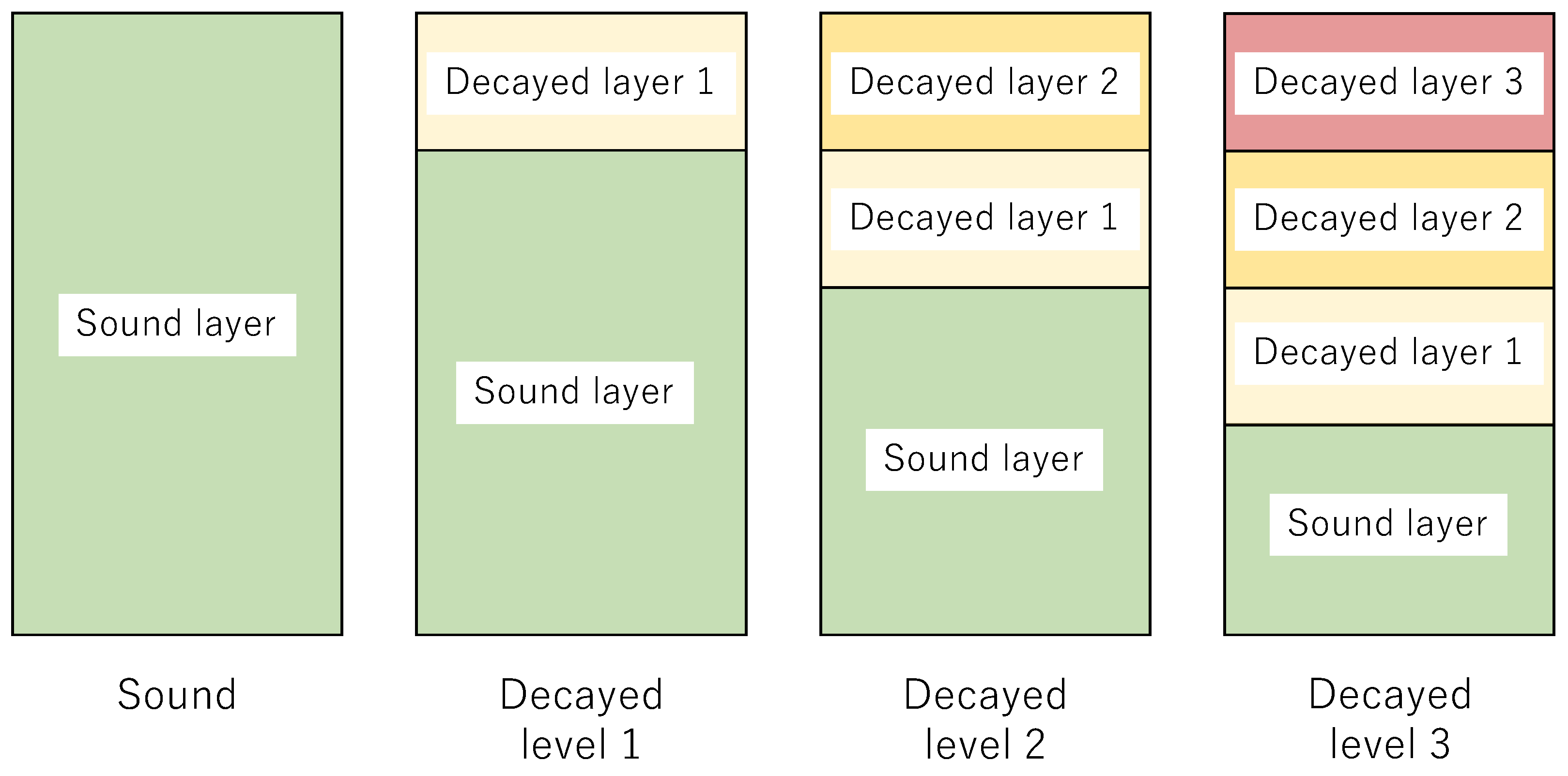
In the single-layer model [22], the bearing strength of a damaged member was uniformly determined based on the driving depth. In the current study, the bearing strength estimated using the driving depth is applied only to the surface layer. Figure 3 illustrates the degradation layer models for each decay level. Each decay layer refers to decay levels 1–3. In the case of decay level 1, the member is modeled as two layers: decay layer 1 and the sound layer. In the case of decay level 2, the member is modeled as three layers: decay layer 2, decay layer 1, and the sound layer at the surface. In the case of decay level 3, the member is modeled as four layers: decay layers 3, 2, and 1 and the sound layer. This division of layers is conscious of the performance evaluation in terms of structural design. In fact, evaluation according to depth is possible.
The thickness of each layer of the degradation layer model is determined by the balance between the energy of the Pilodyn and the energy absorbed by the wood when the pin is driven in. This study assumes that the pin is driving into the wood using potential energy (6 J) released by a spring in the Pilodyn, where the potential energy becomes 0 at the stopping position. Equation (10) depicts the relationship between the bearing strength and energy of sound wood. Here, DP0 is the driving depth of the sound wood, E is the energy possessed by the Pilodyn, and R is the energy absorbed by the wood:
E n   =   F 0   ×   A     ×   D p 0   ×   C
In addition, En is the potential energy of the Pilodyn spring (J), where En = 6.0, F0 is the bearing strength of the sound layer (in N/mm2), A is the sectional area of the driving pin (in mm2), φ   =   2.5   mm ,   A 4.91   mm 2 , Dp0 is the driving depth of the sound layer (in millimeters), and C is the adjustment factor of the energy, being the coefficient of loss due to energy conversion.
The pin is driven from a perpendicular direction to the grain’s direction to measure the penetration depth. In the standard of structural design in Japan [25], if the diameter of the connector is small (e.g., nails), then the shear strength of the joint can be calculated using the same bearing strength regardless of the grain’s direction. In this case, the diameter of the driving pin was small. Thus, we assumed that the bearing strength was the same regardless of the grain’s direction and that there was no friction.
In this study, the energy absorbed by the sound layer and each decay layer per 1 mm of thickness were R0 and Rm (J/mm), respectively. The energy required for the depth of the sound wood (Dp0) is Em (Equation (11)). Moreover, Equation (12) expresses the decayed layer. Furthermore, the values of A and C in the formula are the same, and the Rm of each decay layer is obtained using the F0-to-Fm ratio (Equation (13)):
R 0   =   E n D p 0   =   F 0   ×   A   × C
R m   =   E m D p 0   =   F m   ×   A   × C
R m   =   F m F 0   ×   R 0
Here, R0 is the energy absorption per unit length of sound wood (in J/mm), Em is the energy required when the decay layer m is at Dp0 (J), Rm is the energy absorption per unit length of decayed layer m (in J/mm), and Fm is the bearing strength of decayed layer m (in N/mm2), for which m = 1, 2, and 3.
The subsequent text describes the driving depth and energy used for driving the pin into each decay level.
Equations (14), (16) and (18) indicate that the potential energy of the Pilodyn spring remains constant. In addition, the driving depth is expressed by the sum of the sound layer thickness and each decayed layer’s thickness (Equations (15), (17) and (19)). The thickness of the sound layer and decay layer 1 at the driving depth was determined using the two relationships. To solve the following formula, t1, obtained from decay level 1, is the same value for decay levels 2 and 3, and t2, obtained from decay level 2, is the same value for decay level 3, because it was considered that the same decay level lost the same amount of energy. In addition, t0 was calculated for each decay level.
Decay level 1’s Pilodyn spring potential energy is calculated as follows:
E n   =   ( R 1   ×   t 1 )   +   ( R 0   ×   t 0   )
D p 1   =   t 1 + t 0
That of decay level 2 is expressed as
E n   =   ( R 2   ×   t 2 )   +   ( R 1   ×   t 1 )   +   ( R 0   ×   t 0 )
D p 2   =   t 2 + t 1 + t 0
Finally, the potential energy of the Pilodyn spring in decay level 3 is expressed as
E n   =   ( R 3   ×     t 3 ) + ( R 2   ×   t 2 ) + ( R 1   ×     t 1 ) + ( R 0   ×   t 0 )
D p 3   =   t 3 + t 2 + t 1 + t 0
Here, t0 is the thickness of the sound layer (in millimeters) and tm is the thickness of decay layer m (in millimeters), for which m = 1, 2, and 3.
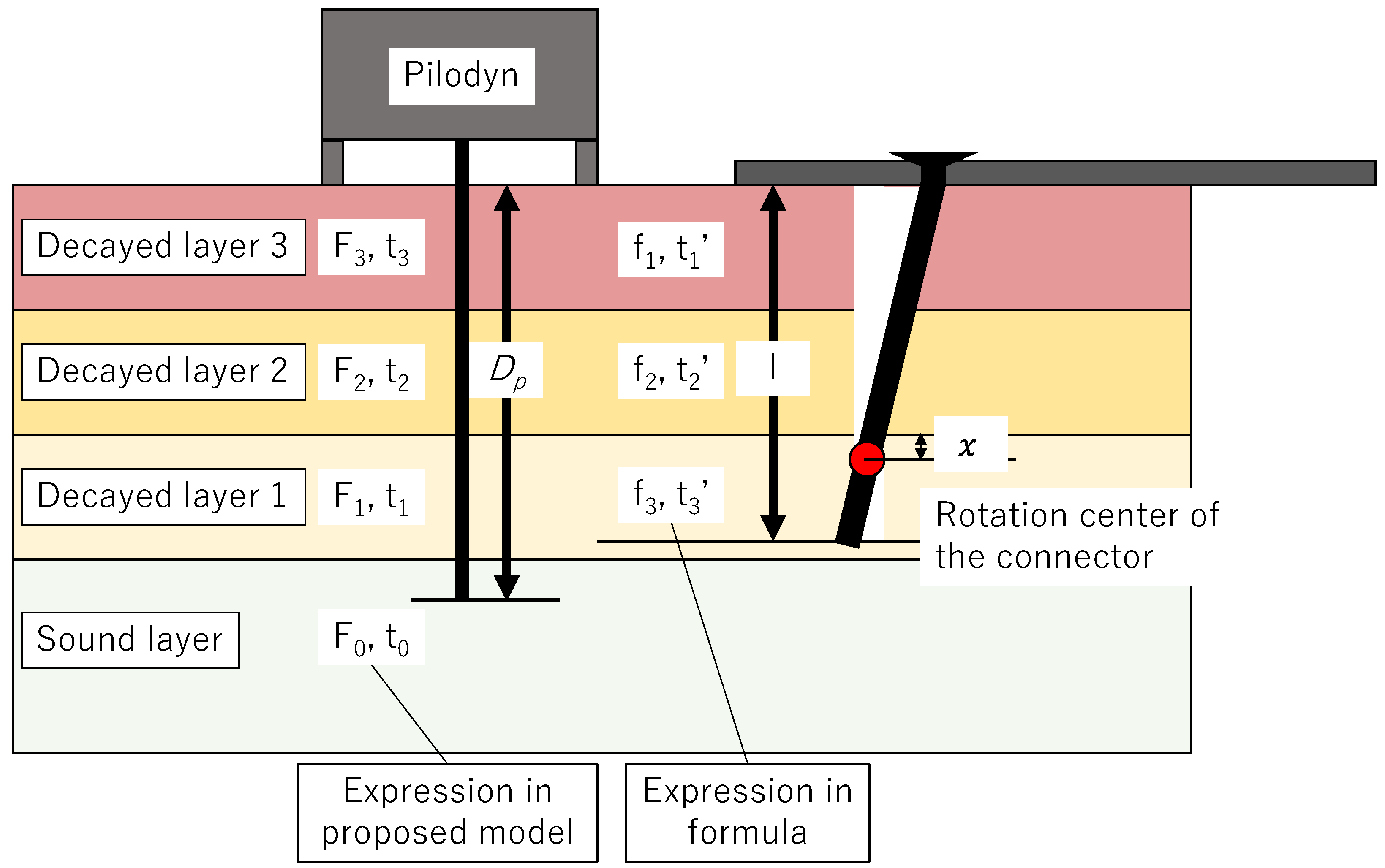
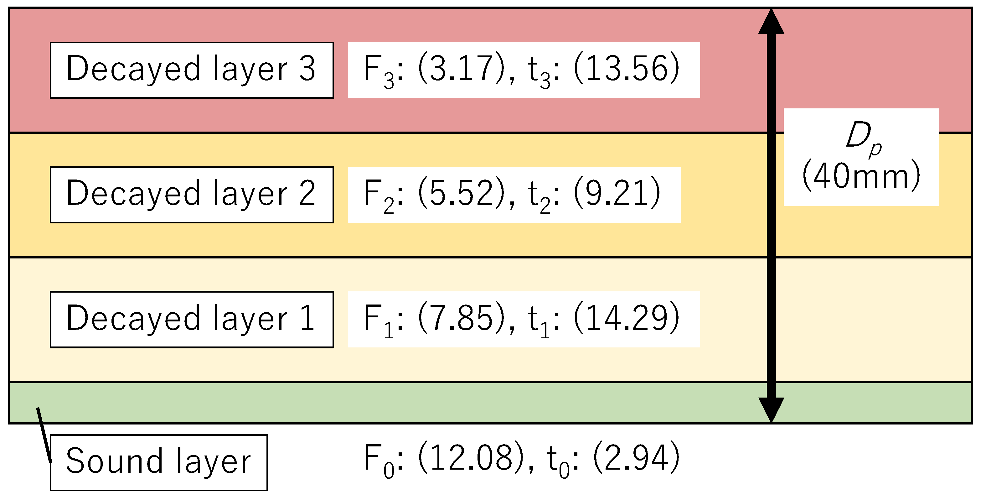
In this model, the number of each layer is counted from the surface. On the other hand, in the formulas for calculating the yield strength (Equations (1)–(9)), the layers are counted from the deepest depth. Therefore, it was necessary to change the reading of the characters when applied to the formulas. Table 1 presents the correspondence between the thickness of the sound layer and each decay layer and the bearing strengths for the number of each layer. Figure 4 depicts the relationship between the yield mode and layer at decay level 3.

2.3. Calculation of Single Shear Yield Strength for Sugi and Todomatu with Decay

The yield strength of screw joints made of decayed Sugi (Cryptomeria japonica) and Todomatsu (Abies sachalinensis) will be compared with the estimated values calculated by the proposed model and the experimental values.

2.3.1. Estimation of Yield Strength for Decayed Todomatsu

The calculated values using the proposed model were compared with the results of single shear tests using decayed Todomatsu [26]. Data derived from 99 decayed specimens and 20 control specimens, which were not affected by rust, were compared with the calculated values. For the decay treatment, a polypropylene container filled with Potato Dextrose Agar medium and topped with a Fomitopsis palustris culture for approximately two weeks was used as the decay source unit. This was placed on the screw joints, wrapped with PVC film to prevent drying and impurities from entering, and sealed with polypropylene tape for curing and forced decay treatment. The duration of the degradation process was a maximum of 140 days. To determine the degree of deterioration of the screw joints, measurements were taken with a Pilodyn, and specimens with decay levels 1–3 were considered decayed specimens. The specifications of the wood screw (CPQ45) were d = 4.07 mm, F = 540 N/mm2, and l = 34 mm.
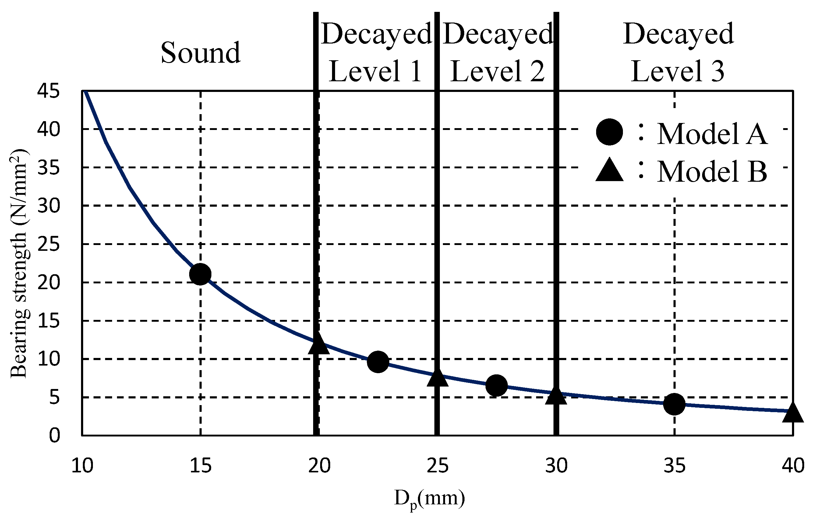
To estimate the yield strength, the relationships between the Pilodyn driving depth and compressive strength or the compressive strength and bearing strength were used. Toda et al. showed the relationship between the residual density and compressive strength parallel to the grain’s direction (parallel compressive strength) in Todomatsu [27]. In addition, Sawada and Yasumura indicated that the ratio between the parallel compressive strength and bearing strength is 0.898 [28]. Based on these relationships, the bearing strength of decayed Todomatsu was calculated using Equation (20). Figure 5 illustrates the relationship between the bearing strength derived using Equation (20) and the Pilodyn value:
F e   =   k   ×   4363   ×   D p 1.93
where k is the factor of proportionality between the parallel compressive strength and bearing strength (0.898), Fe is the bearing strength (in N/mm2), and Dp is the driving depth (in millimeters).
This study describes the case where the bearing strength of the sound layer and each decayed layer used the mean value of each decayed level section (model A (solid circles) in Figure 5) and the case where it used the lowest value of each section of a decayed level (model B (solid triangles)). The average bearing strength of the sound layer became the bearing strength at a driving depth of 15 mm. Table 2 provides the bearing strength of each layer determined with Equation (20). Table 3 indicates the Dp and thicknesses of the sound layer and each decayed layer in models A and B using Equations (10–19). Figure 6 presents an example of the degradation layer model of decay level 3 (model B). In this case, the value C for Models A and B were C A 3.9   ×   10 3 and C B 5.1   ×   10 3 , respectively. In addition, we compared the relationship between the mass loss ratio of the decayed wood and the parallel compressive strength with the experimental values of Toda et al. [27] to confirm whether the thicknesses of the sound layer and each decayed layer were appropriate. The results indicate that each thickness value was generally appropriate, because the calculated values were similar to the experimental values.

2.3.2. Estimation of Yield Strength for Decayed Sugi

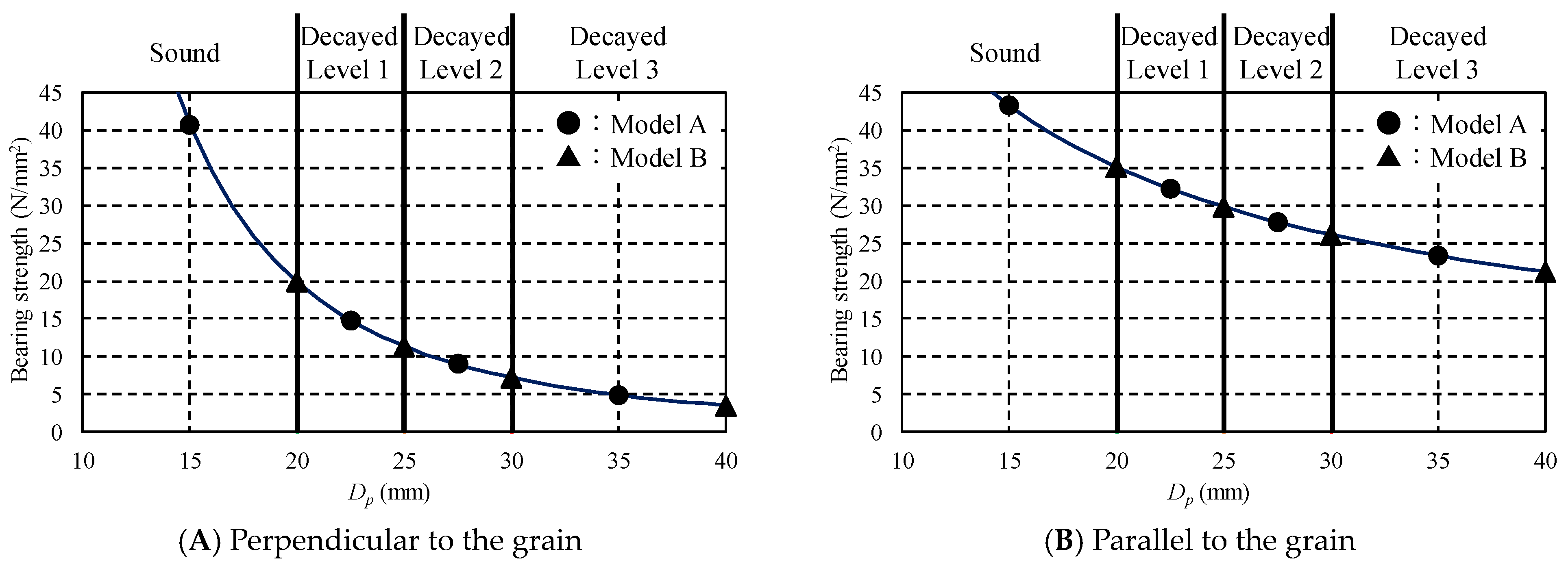
The calculated values using the proposed model were compared with the results of the single shear tests using decayed Sugi [22]. N45 nails (diameter: 2.45 mm) were used for the connector. The experimental results parallel and perpendicular to the grain’s direction were compared to the calculated values. To estimate the yield strength, the relationship between the bearing strength of decayed Sugi and the driving depth reported by Kawano et al. [29] was used. When estimating the thickness of each layer, the relationship between the driving depth and bearing strength perpendicular to the grain’s direction (Equation (21); Figure 7A) was used. In addition, when estimating the single shear strength, the relationship between the driving depth and bearing strength perpendicular to the grain’s direction and parallel to the grain’s direction (Equation (22); Figure 7B) were used. As was the case for the Todomatsu, this study examined model A, which used the mean value of each decayed level (solid circles in Figure 7), and model B, which utilized the lowest value of the degree of deterioration of each section (solid triangles in Figure 7). Table 4 presents the bearing strength of each decayed layer parallel and perpendicular to the grain’s direction, and Table 5 indicates the thickness of each decayed layer calculated using Equations (10–19). The single shear strength was calculated by substituting these values into Equations (1–9):
F   =   34828 × D p 2.493
F   =   307.89 × D p 0.725

3. Results and Discussion

3.1. Estimated Value versus Experimental Value of Decayed Todomatsu

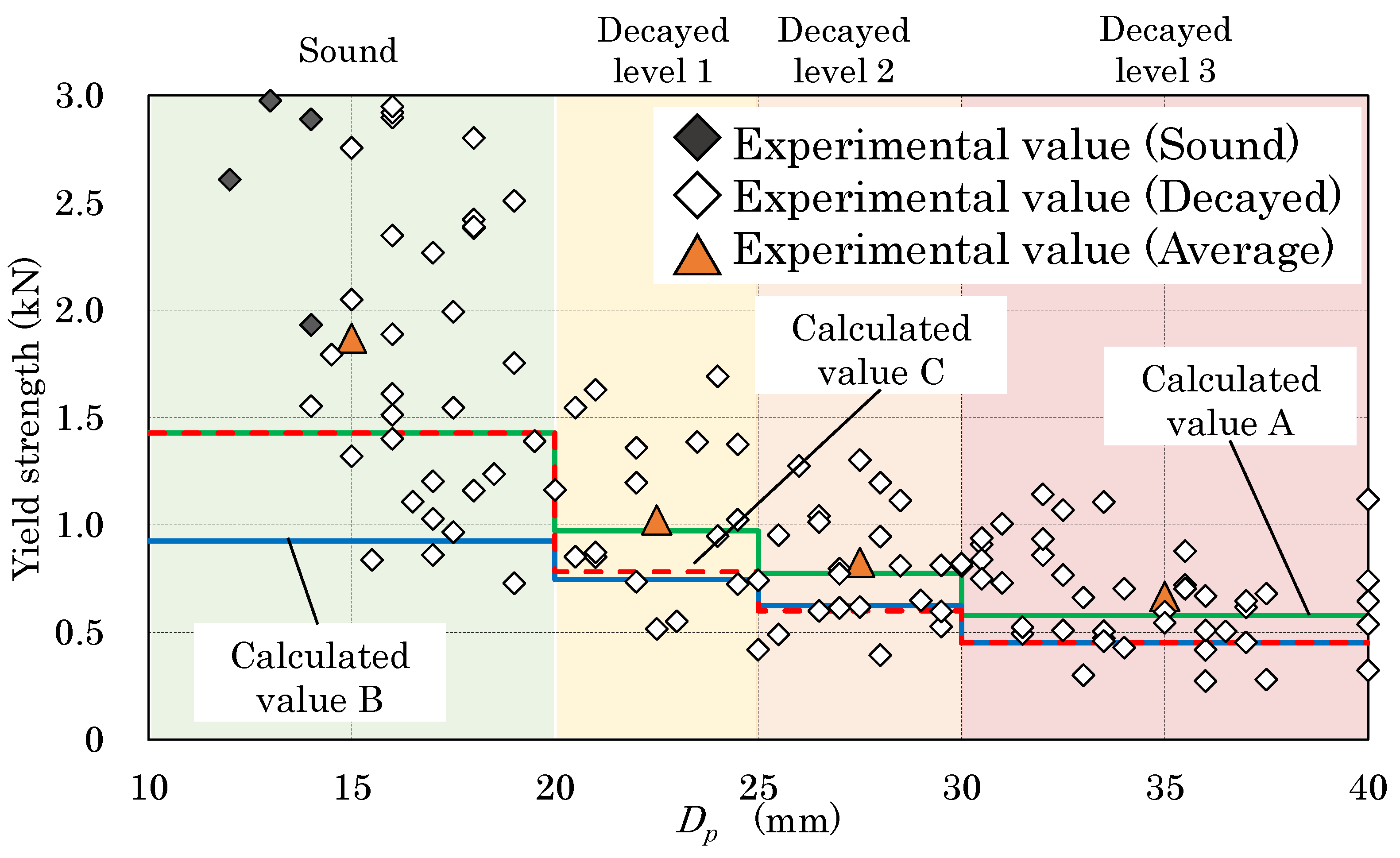
Figure 8 presents a comparison of the experimental value and three calculated values, namely A, B, and C. Specifically, calculated values A and B were based on models A and B using the mean and lowest bearing strength, respectively, whereas calculated value C was based on the single-layer model (existing model). The mean values of the experimental data at each decay level are indicated as triangles in Figure 8.
As a result, calculated values A and B generally indicate the mean and lowest value of the experimental data. When compared across decay levels, calculated value A exhibited a value close to the mean values of the experimental values for decay levels 1 and 2, whereas calculated values B and C generally displayed the lowest values. Based on these results, each calculated value for each calculation range (estimated value corresponding to the bearing strength to be substituted into the formula) was considered a suitable value. In terms of decay levels 1 and 2, calculated value C was approximately 70% of the experimental mean value. However, calculated value A was approximately 95% of the experimental mean value. In this case, model A was considered capable of calculating values that were closer to the mean value. This means that the accuracy of estimating the yield strength of the joints in the early stages of deterioration improved. For decay level 3, the three calculated values were also close, where calculated values B and C produced nearly the same values.
Model B used a degradation layer model but input a lower limit for the bearing strength for each decayed level in each layer for the purpose of estimating the lower limit value. On the other hand, model C assumed that the cross-section uniformly decayed and uniformly reduced the bearing strength, and thus the estimated value was near the lower limit.
Joints in wooden structures were originally characterized by large variations in strength performance. The variation was especially large when decay occurred. In addition, the measurement points of the Pilodyn did not completely correspond to the joint locations. As a result, there were differences between the experimental results and the calculated values.

3.2. Estimated Value versus Experimental Value of Decayed Sugi

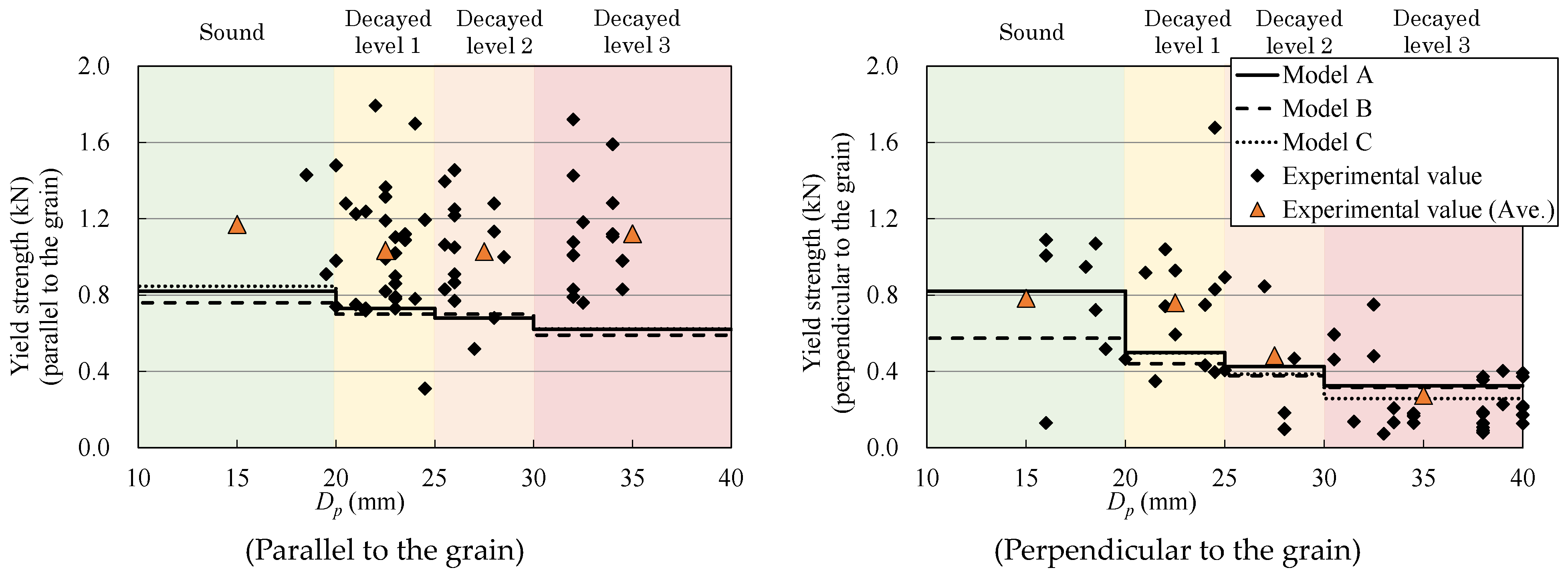
Figure 9 provides a comparison between the estimated and experimental values and presents the specimens parallel and perpendicular to the grain as well as the estimated values of model A using the mean bearing strength value, model B using the lowest value, and model C using the single-layer model (existing model). The mean values of the experimental data at each decayed level are indicated as triangles in Figure 9.
In the direction parallel to the grain, the estimation results of models A, B, and C were approximately at the lower limit of the experimental values, which are considered safe side values. For example, the calculated values using model A were 70%, 66%, and 55% of the experimental average values for decay levels 1, 2, and 3, respectively. In addition, no significant difference was noted in the estimation results among the three models. If the decrease in bearing strength due to the progress of decay (or increase in driving depth) was small, then a difference in the estimated value due to the difference in the modeling method was unlikely to appear.
Regarding the direction perpendicular to the grain, for the specimen with high levels of decay, the estimated value of model A using the mean bearing strength value indicates a rough mean of the experimental values. The calculated values using model A were 66%, 88%, and 118% of the experimental average values for decay levels 1, 2, and 3, respectively. However, model C, which used the existing model, also produced nearly the same values. Model B, which utilized the lowest value, exhibited estimates lower than those of models A and C in the case of sound materials. However, no significant difference was observed among the three models at a driving depth of more than 20 mm. The reason for this result is that when the driving depth was more than 20 mm, no significant difference existed between the bearing strength’s mean value and lowest value in each of the decayed sections, in terms of the relationship between the bearing strength in the current study and the driving depth. When determining the thickness and bearing strength of a layer, if data existed, then the study inferred that the estimation accuracy of the lower limit could be improved by directly using the curve that evaluated the lower limit of the bearing strength.
According to the Standard for Structural Design of Timber Structures [25], when the diameter of the nail is small, no difference in bearing strength is notable perpendicular and parallel to the grain. Moreover, the same value is used. However, in the direction perpendicular to the grain, the effect of additional length was considered lost due to the fiber breakage from the decay’s progress, and thus the experimental value also exhibited a decrease. Therefore, when estimating the single shear strength of decayed wood perpendicular to the grain, the bearing strength must be reduced relative to the parallel direction.

4. Conclusions

To accurately estimate single shear strength performance, this study proposed a new multilayer model that takes into account the gradation of deterioration in a cross-section of decaying wood and divides wood into multiple layers with different strength performance values.
As a result, compared with the existing (single-layer) model, the accuracy of estimating the strength which is considered usable in the early stages of deterioration was improved. The yield strength calculated by inputting the average bearing strength into the proposed model for screw joints in Todomatsu in the early stages of deterioration showed results which were 95% of the experimental average value. On the other hand, it was found that the difference between the proposed model and the existing model was unlikely to appear when the degree of decrease in the bearing strength due to the progress of decay was small.
This study compared experimental results with estimates for specific wood species and screws. Thus, considering the suitability of the model according to wood screw length, shape, and wood species is an interesting avenue for future research.

Author Contributions

Conceptualization, methodology, data curation, and writing—original draft preparation, T.M., R.I. and K.T.; supervision and writing—review and editing, T.M. and K.T. All authors have read and agreed to the published version of the manuscript.

Funding

This work was supported by the JSPS KAKENHI Grant-in-Aid for Scientific Research (B), grant number JP18H01589.

Data Availability Statement

The data that support the findings of this study are available from the corresponding author upon reasonable request.

Conflicts of Interest

The authors declare no conflicts of interest.

References

  1. Akyildiz, H.M. Screw-nail withdrawal and bonding strength of paulownia (Paulownia tomentosa Steud.) wood. J. Wood Sci. 2014, 60, 201–206. [Google Scholar] [CrossRef]
  2. Cappellazzi, J.; Konkler, J.M.; Sinha, A.; Morrell, J.J. Potential for decay in mass timber elements: A review of the risks and identifying possible solutions. Wood Mater. Sci. Eng. 2020, 15, 351–360. [Google Scholar] [CrossRef]
  3. Ota, Y.; Ishiyama, H.; Okamoto, S. Study on the structural performance of plywood bearing wall the rusted nail and decayed wood. Proc. World Conf. Timber Eng. 2023, 2023, 2617–2626. [Google Scholar]
  4. Olaf, S. Indoor wood-decay basidiomycetes: Damage, causal fungi, physiology, identification and characterization, prevention and control. Mycol. Prog. 2007, 6, 261–279. [Google Scholar]
  5. Frederick, G.T.; Terry, L.H. Brown-rot wood decay—Insights gained from a low-decay isolate of Postia placenta. Plant Pathol. 1997, 1, 1–17. [Google Scholar]
  6. Harada, M.; Hayashi, Y.; Hayashi, T.; Karube, M.; Ohgawa, T. Effect of moisture content of members on mechanical properties of timber joints. J. Wood Sci. 2005, 51, 282–285. [Google Scholar] [CrossRef]
  7. Hijikuro, K.; Ono, Y. Field survey into deterioration degradation states for structural member of wooden house. AIJ J. Technol. Des. 1999, 9, 41–44, In Japanese. [Google Scholar] [CrossRef]
  8. Sonoda, S.; Nakatani, H.; Hasegawa, M.; Shiba, K.; Hata, M. Damage to wooden houses by the niigataken Chuetsu-oki Earthquake in 2007. Bull. Toyama Prefectural. Agric. For. Fish. Res. Cent. 2009, 1, 6–17. (In Japanese) [Google Scholar]
  9. Wilcox, W. Review of literature on the effects of early stages of decay on wood strength. Wood Fiber 1978, 9, 252–257. [Google Scholar]
  10. Gilfillana, J.R.; Gilbertb, S.G. Development of a technique to measure the residual strength of woodworm infested timber. Constr. Build. Mater. 2001, 15, 381–388. [Google Scholar] [CrossRef]
  11. Gao, S.; Wang, X.; Wiemann, C.M.; Brashaw, K.B.; Ross, J.R.; Wang, L. A critical analysis of methods for rapid and nondestructive determination of wood density in standing trees. Ann. For. Sci. 2017, 74, 27. [Google Scholar] [CrossRef]
  12. Mäkipää, R.; Linkosalo, T. A non-destructive field method for measuring wood density of decaying logs. Silva Fenn. 2011, 45, 1135–1142. [Google Scholar] [CrossRef]
  13. Thaler, N.; Lesar, B.; Humar, M. Correlation between brown rot decay Pilodyn measurements. Eur. J. Wood Prod. 2012, 70, 893–895. [Google Scholar] [CrossRef]
  14. Takanashi, R.; Sawata, K.; Sasaki, Y.; Koizumi, A. Withdrawal strength of nailed joints with decay degradation of wood nail corrosion. J. Wood Sci. 2017, 63, 192–198. [Google Scholar] [CrossRef]
  15. Sawata, K.; Sasaki, T.; Doi, S.; Iijima, Y. Effect of decay on shear performance of dowel-type timber joints. J. Wood Sci. 2008, 54, 356–361. [Google Scholar] [CrossRef]
  16. Kent, S.; Leichti, R.; Rosowsky, D.; Morrell, J. Effects of wood decay by postia placenta on the lateral capacity of nailed oriented strandboard sheathing and Douglas-fir framing members. Wood Fiber Sci. 2004, 36, 560–572. [Google Scholar]
  17. Kent, S.M.; Leichti, R.J.; Rosowsky, D.V.; Morrell, J.J. Effects of decay on the cyclic properties of nailed connections. J. Mater. Civ. Eng. 2005, 17, 579–585. [Google Scholar] [CrossRef]
  18. Sawata, K.; Sasaki, Y. Lateral strength of nailed timber connections with decay. J. Wood Sci. 2018, 64, 601–611. [Google Scholar] [CrossRef]
  19. Ueda, R.; Sawata, K.; Takanashi, R.; Sasaki, Y.; Sasaki, T. Degradation of shear performance of screwed joint caused by wood decay. J. Wood Sci. 2020, 66, 42. [Google Scholar] [CrossRef]
  20. Nishino, S.; Shibao, M.; Nagami, T.; Taki, Y.; Mori, T.; Tanaka, K. Propose on Database for Evaluation Method of Residual Performance of Wooden Structure with Bio-deterioration. In Summaries of Technical Papers of Annual Meeting of AIJ, Sendai, Japan 2018; Architectural Institute of Japan: Tokyo, Japan, 2018; pp. 609–610. (In Japanese) [Google Scholar]
  21. Mori, T.; Tanaka, K.; Mouri, Y.; Yanase, Y.; Inoue, M.; Isoda, H. Study on survival strength of wood screwed joint after termite attack. J. Struct. Constr. Eng. AIJ 2016, 81, 1113–1120. [Google Scholar] [CrossRef]
  22. Mori, T.; Tanaka, K.; Kawano, K.; Nakahata, T.; Yanase, Y.; Kurisaki, H. Estimation of shear strength of nail driven into decayed wood of Japanese cedar sugi. J. Soc. Mater. Sci. Jpn. 2014, 63, 314–319, In Japanese. [Google Scholar] [CrossRef]
  23. Maeda, K.; Ohta, M.; Momohara, I. Changes of Cross Sectional Area and Density of the Decayed Wood. Wood Ind. 2015, 70, 153–157. (In Japanese) [Google Scholar]
  24. Tomitaka, R.; Toda, M. Application of European Yield Theory to Laminated Timber composed of Lumber with any Thickness and Bearing Strength. Summ. Tech. Pap. Annu. Meet. AIJ 2018, 72, 555–556. (In Japanese) [Google Scholar]
  25. Architectural Institute of Japan. Standard for Structural Design of Timber Structures; Maruzen: Tokyo, Japan, 2006; p. 31. (In Japanese) [Google Scholar]
  26. Mori, T.; Noda, Y.; Azuma, T.; Mori, M.; Toda, M.; Isoda, H. Evaluation of Single Shear Strength Performance of Wood Screw Joint Driving into Compulsive Decayed Wood. J. Struct. Eng. B 2015, 61B, 237–242. (In Japanese) [Google Scholar]
  27. Toda, M.; Mori, M.; Ohashi YMHirai, T. Effects of Wood Decay on the Shear Performance of Nailed Timber Joint. Mokuzai Gakkaishi 2010, 56, 41–47, In Japanese. [Google Scholar] [CrossRef]
  28. Sawata, K.; Yasumura, M. Determination of embedding strength of wood for dowel-type fasteners. J. Wood Sci. 2002, 48, 138–146. [Google Scholar] [CrossRef]
  29. Kawano, K.; Nakahata, T.; Mouri, Y.; Mori, T.; Tanaka, K.; Inoue, M. Surviving Strength Properties of Japanese Softwood with Biodeterioration Part.3 Estimation of shear strength of nail joint into decayed wood of Japanese cedar. In Summaries of Technical Papers of Annual Meeting of AIJ, Kobe, Japan, 2014; Architectural Institute of Japan: Tokyo, Japan, 2014; pp. 387–388. (In Japanese) [Google Scholar]
Figure 1. Model for estimating residual strength of wood with biodeterioration.
Buildings 14 01924 g001
Figure 2. Yield mode of screw joint.
Buildings 14 01924 g002
Figure 3. Degradation layer models for each decayed level (decaying from the top).
Buildings 14 01924 g003
Figure 4. Relationship between the yield mode and the layer at decayed level 3.
Buildings 14 01924 g004
Figure 5. Relationship between the bearing strength and Pilodyn value (Todomatsu).
Buildings 14 01924 g005
Figure 6. Example of the degradation layer model of decayed level 3 (model B).
Buildings 14 01924 g006
Figure 7. Relationship between the bearing strength and Pilodyn value (Sugi).
Buildings 14 01924 g007
Figure 8. Comparison of calculated and experimental values (Todomatsu). (Green: Calculated value A, Blue: Calculated value B, Red: Calculated value C).
Buildings 14 01924 g008
Figure 9. Comparison of calculated and experimental values (Sugi).
Buildings 14 01924 g009
Table 1. Correspondence between the thickness of each layer and bearing strength for each layer’s decayed level.
Character in the formulat1′ (f1)t2′ (f2)t3′ (f3)t4′ (f4)
Character to be assigned to formulasDecayed level 1t1 (F1)t0 (F0)--
Decayed level 2t2 (F2)t1 (F1)t0 (F0)-
Decayed level 3t3 (F3)t2 (F2)t1 (F1)t0 (F0)
Table 2. Bearing strength of each layer (Todomatsu).
Fm (N/mm2)
Model ASound layerF021.05
Level 1 layerF19.62
Level 2 layerF26.53
Level 3 layerF34.10
Model BSound layerF012.08
Level 1 layerF17.85
Level 2 layerF25.52
Level 3 layerF33.17
Table 3. Driving depth and calculated thickness (Todomatsu).
Decayed
Level
Dp
(mm)
Thickness of Sound Layer and Each Decayed Layer (mm)
t 3 t 2 t 1 t 0
Model ASound15.000015.00
Level 122.50013.828.68
Level 227.507.2513.826.43
Level 335.09.327.2513.824.62
Model BSound20.000020.00
Level 125.00014.2910.71
Level 230.009.2114.296.50
Level 340.013.569.2114.292.94
Table 4. Bearing strength of each layer (Sugi).
Fm (N/mm2)
Perpendicular to the GrainParallel to the Grain
Model ASound layer40.7343.22
Level 1 layer14.8232.22
Level 2 layer8.9927.85
Level 3 layer4.9323.39
Model BSound layer19.8835.09
Level 1 layer11.4029.85
Level 2 layer7.2426.15
Level 3 layer3.5321.23
Table 5. Driving depth and calculated thickness (Sugi).
Decayed
Level
Dp
(mm)
Thickness of Sound Layer and Each Decayed Layer (mm)
t 3 t 2 t 1 t 0
Model ASound15.00.000.000.0015.00
Level 122.50.000.0011.7910.71
Level 227.50.006.4211.799.29
Level 335.08.536.4211.798.26
Model BSound20.00.000.000.0020.00
Level 125.00.000.0011.7213.28
Level 230.00.007.8611.7210.42
Level 340.012.167.8611.728.26
Disclaimer/Publisher’s Note: The statements, opinions and data contained in all publications are solely those of the individual author(s) and contributor(s) and not of MDPI and/or the editor(s). MDPI and/or the editor(s) disclaim responsibility for any injury to people or property resulting from any ideas, methods, instructions or products referred to in the content.