Article

Scenarios of Progressive Pancake/Bending Collapse Considering Elastic/Plastic Reinforced Concrete Buildings

by
Enrico Zacchei
1,2,* and
Caio Gorla Nogueira
3
1
Itecons, 3030-289 Coimbra, Portugal
2
University of Coimbra, CERIS, 3004-531 Coimbra, Portugal
3
College of Engineering, São Paulo State University (UNESP), 14-01 Eng. Luís Edmundo Carrijo Coube Avenue, Bauru 17033-360, São Paulo, Brazil
*
Author to whom correspondence should be addressed.
Buildings 2024, 14(7), 1948; https://doi.org/10.3390/buildings14071948
Submission received: 5 October 2023 / Revised: 26 November 2023 / Accepted: 28 November 2023 / Published: 27 June 2024

Abstract

:
Quantitative analyses of structural resistance are useful during the design process to prevent the occurrence of progressive collapse. Buildings subjected to continuous instances of expected/non-expected loadings due to extreme events (e.g., earthquakes, explosions, floods, hurricanes) can collapse. A lack of specific knowledge from the designer and poor maintenance can affect collapse analyses. In this paper, the probability of failure for pancake collapse with respect to bending collapse for reinforced concrete (RC) multi-storey buildings is estimated. New combinations regarding the elastic/plastic behaviour of the material under distributed loadings on beams are proposed. Numerical 2D finite element method (FEM) analyses are carried out to model these buildings. Also, simplified dynamic analyses are carried out. The outputs are plotted in terms of the probability of failure for pancake collapse as a function of column compressive strength and the number of removed columns. The results show that the presence of elastic beams can influence the pancake collapse of columns, and, for buildings composed of several elements, the elimination of few elements has little impact on their stability.

1. Introduction

The collapse of the Ronan Point building in 1968 due to an internal gas explosion is considered a classic example of progressive collapse [1,2]. The collapse of structures can be caused by different events, e.g., earthquakes, impact loadings, explosions, etc. Particular attention to the latter event is necessary since it can be caused by terrorist attacks [3,4,5], as registered in New York (2001), Madrid (2004), Stockholm (2010), Moscow (2011), and Boston (2013).
Studies of these events regarding structural collapse have shown the great vulnerability of these structures and inappropriateness of their design [6]. The concept of robustness, often associated with collapse, is related to a structure’s ability to not suffer excessive damage in a disproportionate way to the causative event. Unless the structure is designed to remain in service after one of its columns is collapsed by an explosion, it is usually strong enough to withstand such an attack without collapsing, adopting specific details.
Several engineers and researchers have focused on this issue and its mechanisms (e.g., bending and pancake, discussed in the present paper [4,7]).
Some codes [8] recommend prescriptive strategies for limiting or even avoiding progressive collapse. These strategies require minimum amounts of ductility, redundancy, and special structural arrangements, e.g., using the (i) high toughness of structural members and their interconnections [9], and (ii) the alternative load path method [10,11], which involves suddenly removing one key element and measuring the extent of the subsequent collapse [12].
These measures do not indicate steps to achieve progressive collapse and they are not always enough to prevent progressive collapse [13,14]. Hence, structures are first designed and subsequently tested against those robustness criteria. This means that progressive collapse is not considered a priori, but mostly at the design phase [4].
Regarding structural redundancy, i.e., the capacity to redistribute the loads when a damage process acts on some parts of a structure, in the literature, the lack of this capacity is considered a main cause for collapse [6,15]. In particular, “passive” redundancy can be a strong mechanism to guarantee the robustness of the structure and avoid collapse. Passive redundancy regards the structural elements as being in a “stand-by” situation but states that they come into operation when any structural element fails.
In anti-seismic codes [16,17], the capacity design requires a hierarchy of the structural elements, ensuring that earthquakes can only provoke ductile collapse of the horizontal beams, whereas the failure of columns and brittle ruptures attributable to shear are inhibited.
Strategies to improve progressive collapse resistance include the following: (i) compartmentalization of the structure (i.e., to decide what are the expendable parts of a building) and (ii) the delocalization of stresses after local damage. The delocalization of stresses can be achieved by improving moment-resisting connections in pile-beam nodes, e.g., for precast concrete structures [12] and steel structures [13,18,19]. Moreover, (iii) catenary effects in the floor slabs can remarkably improve robustness, as discussed in [14].
More recently, these themes have been treated in different ways. In [2], progressive collapse was studied by considering the effects of novel and alternative structural detailing for reinforced concrete (RC). In [3], the influence of the infilled walls in prestressed RC elements on progressive collapse was analyzed. In [5], the potential progressive collapse behaviour of innovative steel fibre-reinforced rubberized concrete was evaluated. In [11], progressive collapse was assessed by considering the torsional effects for monolithic precast concrete. Finally, in [20,21], the authors also highlighted the concept of pounding with neighbouring buildings as a potential factor contributing to the collapse of columns or beam frames within structures.
All these analyses contain several uncertainties which cannot be neglected when more accurate predictions of collapse are needed. In this regard, the assessment of some important parameters, which control (e.g., column removal time [12]) and give information on the status of the collapse process (e.g., external loadings and internal stresses), should be carried out via probabilistic approaches to better predict the durability of RC structures in a more accurate way. Most uncertainties can be modelled as random variables. Reliability analyses estimate the probability of collapse by accounting for several parameters. Therefore, these probabilistic approaches consider the uncertainties and their effects more consistently, providing more detailed information to better make decisions in engineering projects, especially when durability aspects are present.
This paper studies progressive collapse by using probabilistic methods. In particular, the probability of failure for pancake collapse with respect to bending collapse for RC multi-storey buildings is estimated. The considered behaviour of the material is elastic and plastic. The general concept is to understand the 2D structural behaviour of three building types after the removal of some columns. Iterative dynamic analyses are also developed.
This paper represents an extension of [10]; in this sense, the main novelties of this paper consist of developing new combinations for pancake collapse in a global system and proposing a new limit state (LS) function for reliability analyses.

2. Structural Scheme

2.1. Dynamic Equilibrium

The scheme is represented by a 2D hierarchical structure. A structure is called “hierarchical” when it has a primary structure, which is made of some massive structural elements that support a secondary one. The studied structure is formed by reinforced concrete (RC) elements with horizontal beams (floors) and vertical columns fixed on the ground [22]. A 2D framed structure should be enough to reveal different local rupture modes, as already discussed in [10,23].
The structural equilibrium is represented by a simplified dynamic scheme, whereas the behaviour of the material can be elastic or plastic (discussed in Section 2.2). The external actions come from the ground horizontal accelerations, x ¨ e t .
For each degree-of-freedom (DOF), the dynamic equilibrium in the time, t, is expressed by the following [24]:
M   x ¨ t +   x ˙ t + K   x t = M   l   x ¨ e t
where M R n × n and K R n × n are the mass and stiffness matrices, respectively. The former matrix is formed by coefficients mj > 0 (j = 1, 2, …, n), which represent the j-th floor lumped masses where j = 1 refers to the first floor, whereas the latter matrix is formed by kj > 0, which denotes the elastic stiffness coefficients between j-th and (j + 1)-th floor [22]. The damping matrix, R n × n , formed by coefficients, cj, is expressed under the classical Rayleigh damping assumption.
The components of x t = x 1 t ,   x 2 t ,   ,   x n t T R n are the floor displacements which refer to the ground level. Variables x ˙ t and x ¨ t represent the first and second time derivate of x(t), respectively. Matrix l = 1 ,   1 ,   ,   1 T R n accounts for the distribution of the external action x ¨ e t = x e , 1 t ,   x e , 2 t ,   ,   x e , n t T R n .
Figure 1 shows an example of a studied building (columns + beams) and two collapse mechanisms, i.e., bending and pancake collapse (explained in Section 2.2), that can occur in the structure. The formation of the plastic hinges is indicated by red points.
During shaking, the intact structure is equilibrated under gravity loadings. If some elements fail during this initial phase, the structure is incapable of carrying the service loadings, and the dynamic motion stops [14,26].
This scheme is valid only for the elimination of the central columns; thus, the elimination of edge columns is not considered here [13]. Therefore, the scheme allows for elimination up nc − 2 columns, where nc  is the number of columns of the structure [10].

2.2. Collapse Loadings

The columns transmit vertical concentrated forces to other columns at a lower storey and to the beams over the damage area. Concrete buildings with typical structural configurations are subjected to progressive collapse by local failure of a vertical support member [5]. In this sense, it is necessary to evaluate different models to capture the interaction between bending moment and compressive force.
Collapse loadings generate a localized failure of a primary load-bearing element, which affects multiple adjacent portions of the structure [16]. The sudden loss of a column generates two main effects: (i) increase in the beam length supported by the columns and (ii) downward inertial amplification of gravity forces [16,25]. In both situations, the structural elements must redistribute the amplified loadings to the neigh elements to re-achieve equilibrium [16].
Gravity and external aleatory loadings generate the developing of axial, shear, bending moments, and torsional moments in structural members. These forces determine the static equilibrium state of the structure; for this, they are considered during the conventional design stage. However, aleatory events provide the unknown redistribution of these forces in terms of magnitudes and directions.
Knowledge of the redistribution of the stresses in the structural elements produced by column removal is crucial before estimating the progressive collapse assessment. The key is to individuate the positions of the loadings in the damaged structure (i.e., without columns). It is assumed that the sudden application of the gravity load without the columns captures the response of the structure to progressive collapse. In this sense, in the approach used in this paper, the modelling of the internal reaction forces is not required.
In the present analysis, two types of collapse, including loading, have been considered. The first is called “bending collapse”, where beams collapse for flexure and the structure is subjected to being pushed upwards [27]; in this case, columns are stiffer than beams. The second is called “pancake collapse”, where columns are subjected to buckling under compressive forces. In this case, columns exert a push toward the outside. This division is consistent with the classic requirement to find “strong-column-weak-beam”, as discussed in [2].
The loadings are considered to be uniformly distributed, q, on the horizontal beams, which transmit the loadings on the vertical columns.
Figure 2 shows the sequences used to carry out the collapse analysis, from the identification of collapse types to the identification of geometrical systems. The sequences are divided into the following: (i) collapse types as bending, pancake [10], hammering, drag, base cutting [4]; (ii) collapse moments, which refer to the time, i.e., before and after damage; (iii) behaviour of the structural elements, which can be prefect brittleness (henceforth called “elastic”) and ideal plasticity (henceforth called “plastic”); and (iv) systems, which define the geometric references.
Progressive collapse of framed structures after damage consists of an initial triggering and thus a subsequent damage propagation. If the initial damage is small, collapse initiation is generally a local phenomenon only affecting the surroundings of the initially damaged area. Global mechanisms can occur only in thin structures with enough stiffness capacity to avoid the compartmentalization effect produced by ruptures. Nevertheless, if the starting damage is more serious than the removal of a single column, global mechanisms can be expected also for larger and more plastic structures.
The parameters used to define the collapse are the moment yield threshold, By, in the beams neglecting shear and axial forces and the compressive strength, Rc, in the columns. Therefore, when element strength is reached, two possible scenarios, as already mentioned, regarding the behaviour can happen.
In the following Section 2.2.1 and Section 2.2.2, the analytical relations are shown in accordance with the literature [10,23].

2.2.1. Bending Mechanisms

The bending mechanism (superscript “B”) is defined by a simplified static scheme, which is represented by a bi-fixed beam to the columns subjected to distributed loading, q. With these conditions, the elastic (superscript “el”) loading that refers to the intact structure (subscript “i”) before damage can be expressed as follows:
q i B , el = 12   B y L 2
where L is length of the beam (By has been already defined). By considering the triple-hinge plastic mechanism in the beam (two plastic hinges at the ends and one in the middle), the plastic (superscripts “pl”) loading that refers to the intact structure before damage can be expressed as follows:
q i B , pl = 16   B y L 2
After damage, the static scheme changes; in particular, the beam is fixed at one end, and at the other end only the vertical displacement is free. In addition to loading q, there is a concentred external force at the free end (=0.5 q L (nr,c − 1), where nr,c is the number of the removed column). Here, the elastic loading after damage (subscript “d”) can be expressed as follows:
q d B , el = 12   B y L 2 6   n r , c + 1
For several plastic hinges at the ends of the beam, the plastic loading after damage is as follows:
q d B , pl = 4 B y L 2   n r , c
The concentration of the bending moment is the connection between a beam hanging above the damage area, and the first intact column depends on nr,c number.

2.2.2. Pancake Mechanisms

The pancake mechanism (superscript “P”) is here described. The elastic loading before damage is expressed as follows:
q i P , el = R c L   n s
where ns is the number of storeys of the structure (Rc has been already defined). In the after-damage situation, two reference systems have been identified: local (superscript “loc”) and global (superscript “gl”). The elastic loading in the local and global system is defined by, respectively, the following:
q d P , el , loc = R c L   n s 1 1 +   n r , c
q d P , el , gl = R c L   n s 1   f r 1 +   f r
where fr is the fraction of columns removed at one storey, which is defined by the following ratio fr = nr,c/nc < 1. Finally, the plastic loading in the local and global system is defined by, respectively, the following:
q d P , pl , loc = R c L   n s 2 2 +   n r , c
q d P , pl , gl = R c L   n s 1 f r

2.2.3. Activation of Collapse Mechanisms

To individuate the more critical collapse loading (bending or pancake), it is necessary to find the collapse mechanism to be activated in the structure. The activation of the collapse mechanism can be estimated by the mechanism parameter, mp [10]:
m p = R c   L B y   n s
By combining Equations (4) and (5) with Equations (8) and (10), it is possible to obtain four possible combinations for pancake collapse in a global system to define a new parameter mpP:
Combination   1 :     q d P , pl , gl q d B , el < 1 m p < m p P = 12 1   f r ( 6 n r , c + 1 )
Combination   2 :     q d P , pl , gl q d B , pl < 1 m p < m p P = 4 n r , c   1   f r
Combination   3 :   q d P , el , gl q d B , el < 1 m p < m p P = 12   1 +   f r 1   f r ( 6 n r , c + 1 )
Combination   4 :   q d P , el , gl q d B , pl < 1 m p < m p P = 4   1 +   f r n r , c   1   f r
These combinations account for the loadings ratio that provides some types of collapse due to plastic columns with respect to elastic/plastic beams, or elastic columns with respect to elastic/plastic beams.
Note that only combination 1 was used in [10], whereas combinations 2, 3, and 4 represent an extension of [10]; in this sense, they can be considered new combinations and contributions.

3. Material and Methods

3.1. Materials

Data have been collected considering a (i) determinist approach where the values represent the geometry and material characteristics of the building and a (ii) probabilistic approach where both parameters Rc and By represent the internal stresses of the building, which are generated by several random variables (RVs).
Table 1 lists the deterministic parameters and their values for the three structure types.
A continuous element can be cut in ∞ different ways and, therefore, there are ∞e possible fundamental structures, where “e” is the number of elements. In this sense, for three cases, nc and ns are predefined to obtain three equivalent buildings in terms of H and L.
It is important to highlight that cases 1 and 2 could correspond to ideal buildings since H and L reach very high values, whereas case 3 could be considered a real building. More realistic scenarios would involve columns with a small cross-section and highly reinforced tall beams [23]. The general criterium was to construct symmetric buildings with the same total length and height, in a similar way to the literature [10].
Figure 3 shows the model scheme. The logic consists of estimating the effects on the structure’s stability when some columns are removed. The removed parts can be caused by an accidental damage event; however, the characteristics of the possible event were not studied here [7]. After removing the structural elements, the internal stress reorganizes. It is possible to idealize a graph of multi-directional stress associated with each element. The search of the set of rooted trees of a graph coincides with the extraction of the set of all possible paths of loadings where the branches are the beam and columns, and the nodes are the beam–column intersection [6].
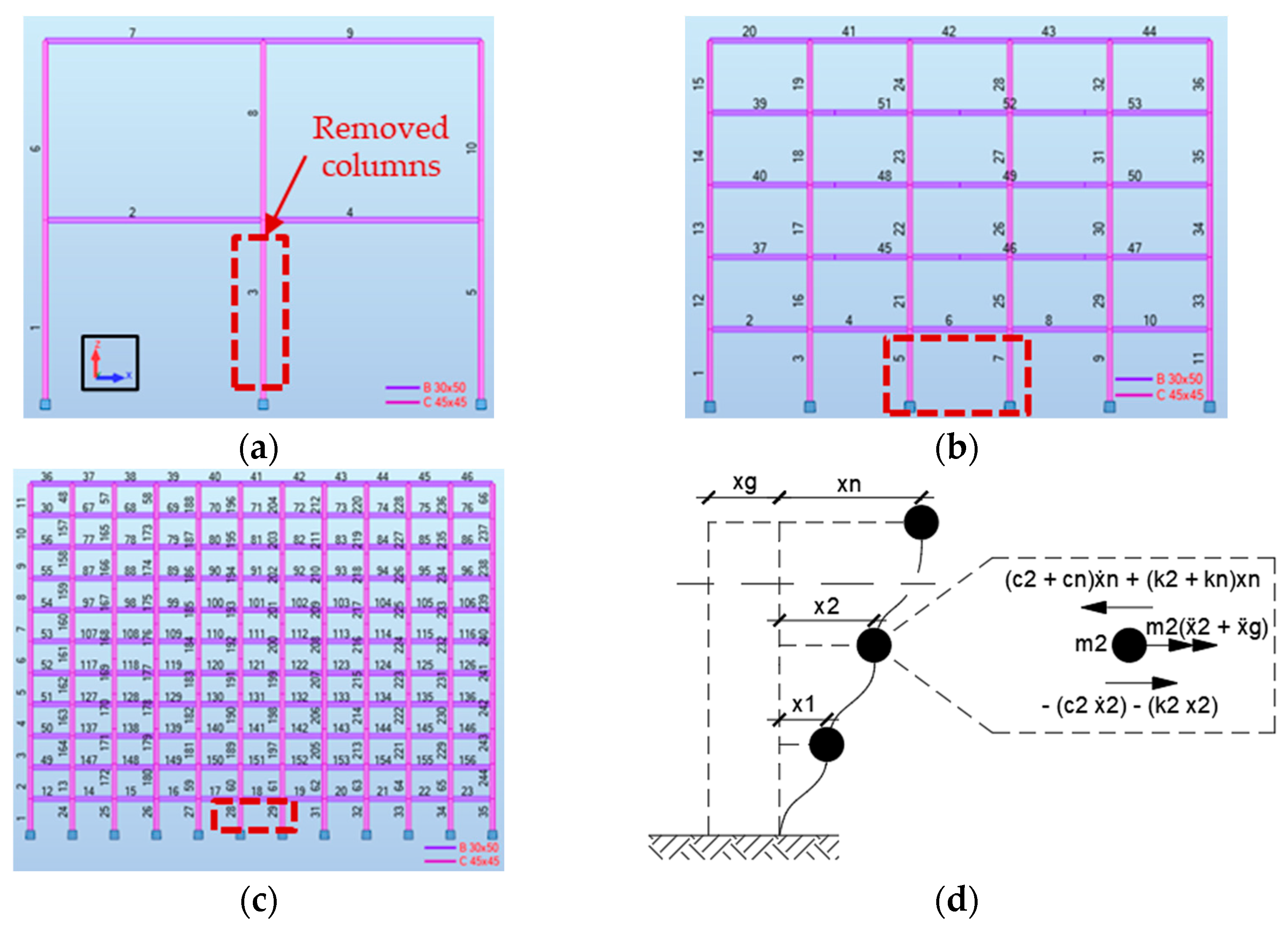
The 2D finite element method (FEM) by software [28] has been used to model the buildings, as shown in Figure 4a–c. Figure 4d shows a structural dynamic scheme already described by Equation (1) (developed in Section 4.2) [29]. The used values are shown in Table 1.
Each element is indicated by a number, and as already mentioned, the nodes at the end of the columns are fixed. The buildings are composed by 9 nodes and 10 elements (case 1), 45 nodes and 52 elements (case 2), and 224 nodes and 243 elements (case 3). The x-axis and z-axis correspond to the horizontal and vertical axis, respectively.
In Figure 4a–c, by a rectangular red area, the removed columns are shown: for case 1, only one column is removed, nr,c = 1.0 (element 3 in the FEM model); for cases 2 and 3, two columns are removed, nr,c = 2.0 (elements 5 and 7 for case 2; elements 28 and 29 for case 3).
Table 2 shows the frequencies, estimated by software [28], and the masses for each case. The frequencies, f (=1/T, where T is the structural period), refer to the predominant modal participating mass ratio (MPMR), which ranges between 81.83 and 94.25%, in x direction.
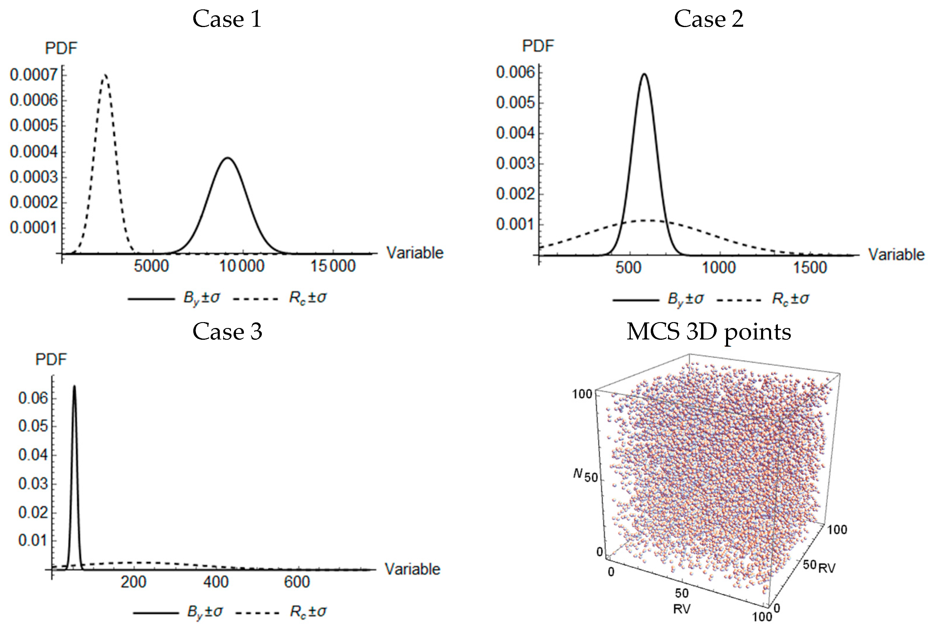
Stochastic analyses have been carried out by using Monte Carlo simulation (MCS), which consists of choosing a probability distribution in the range of RVmin to RVmax up to a list of N random values, i.e., RVmin ≤ μ ≤ RVmax (here, N = 1.0 × 10⁶, and RVmin = RVmax ≈ 0.80 μ). The software Mathematica has been used for this purpose [30]. Table 3 lists the used values, where μ and σ are the mean and standard deviation values, respectively; CV is the coefficient of variation defined by (σ/μ) × 100.
The choice of the μ values for By is similar to that used in [10], whereas the choice of μ values for Rc is due to the fact that the probability of failure for pancake collapse, Pr (Section 3.2.1), must be expressed between 0 and 1.0 for nr,c = 1, 2, …, n. Thus, By values have been estimated a posteriori to evaluate the Pr trends. This leads to carrying out several analyses for all cases and combinations.
Figure 5 shows the probability density functions (PDFs) for the output values (see Table 3) by using Gaussian distributions [31].
In Figure 5, it is possible to note that the PDF curves for Rc move from left to right (from case 1 to case 3). This indicates that for the first structure of 10 elements, By is greater than Rc, whereas for the third structure of 243.0 elements, By is smaller than Rc. This could be consistent with the dynamic behaviour of the structure since, for case 3, the frequency (Table 2) suffers small variations in eliminating a small number of columns.

3.2. Methodology

3.2.1. Probability of Failure for Pancake Collapse

The failure probability of a system with RVs, x n , can be expressed by the following [32,33]:
P f = n I F x f x dx
where IF(x) is the binary indicator function, which is 1.0 if the point x is placed within the failure domain F (F ≤ 0) or limit state (LS), and 0 if F > 0; f(x) is the PDF joint of x.
By assuming x = T(u) to express x in terms of independent standard Gaussian RVs, u, Equation (16) can be written as follows:
P f = n I F T u φ u du
where φ(u) is the multivariate standard Gaussian PDF.
The subset simulation solution of Equation (17) involves the construction of several intermediate failure domains; therefore, the failure domain of interest, F, is expressed by the following:
F = j = 1 M F j
where F1  F2  FM, and F = FM. The failure probability Pf = Pr( u F ) can be written as follows:
P r u F = j = 1 M P r ( u F j | u F j 1 )
where Pr( u F ) = 1. Each Pr( u F j | u F j 1 ) in Equation (19) can be compute by using the following:
P r ( u F j | u F j 1 ) = n I F j u φ ( u | F j 1 ) du
where φ(u|Fj−1) is the truncated φ(u). By using MCS to generate several samples N of φ(u|Fj−1), Equation (20) is approximated as follows:
P r ( u F j | u F j 1 ) 1 N i = 1 N I F j u i = N f N
in which ui is the sample generated from conditional PDF φ(u|Fj−1), and Nf is the number of simulations with IFj(ui) ≤ 0.
The Pr results are considered accurate when the samples N → ∞; in practise, the number of samples N required is 1.0 × 10k, where the choice of k is defined by the convergence analysis (as already mentioned, here k = 6.0) [31,34].

3.2.2. Proposed Limit State Function

In this analysis, the LS function has been written as the difference between mp defined in Equation (11) and the mechanism parameter for pancake mpP (Equations (12)–(15)) as follows: F → G(X) = mp(X) − mpP. To estimate the probability of failure for pancake collapse, Pr, Equation (11) becomes the proposed Equation (22), where mp(X) is expressed in a stochastic way:
m p X = R c X   L B y X   n s
Here, mp(X) is considered to be a semi-probabilistic parameter since the parameters L and ns are a priori defined (see Table 1), whereas By(X) and Rc(X) are calculated in a probabilistic way (see Table 3).
Figure 6 shows three domains defined by the LS function. When G(X) < 0, pancake collapse is verified, whereas when G(X) > 0, pancake collapse is not verified, and bending collapse starts. In this study, only pancake collapse has been quantified.
This division is purely mathematical; in fact, in a physical process, when G(X) > 0, what is difficult is that pancake collapse is not partially activated. Also, in [3], it was shown that, under predefined conditions, flexural collapse happens before compressive collapse.
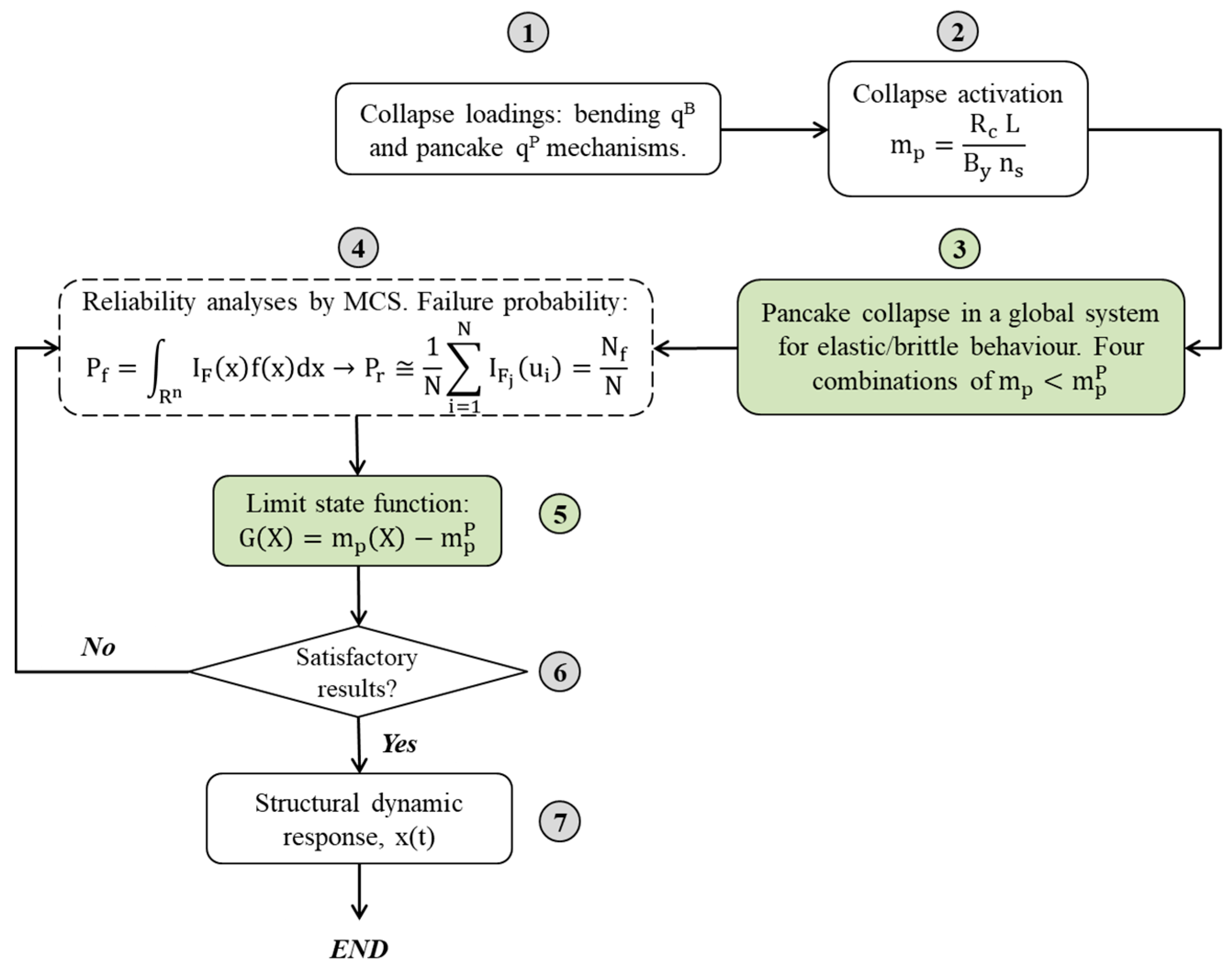
The general methodology is explained by the following steps (see Figure 7): definition of (1) bending and pancake mechanisms and collapse loadings (Equations (2)–(10)); (2) the collapse activation by Equation (11); (3) pancake collapse combinations by Equations (12)–(15).
In step (4), reliability analyses by using MCS (Equation (21)) have been carried out to estimate the probability of failure for pancake collapse.
Then, it is necessary to (5) separate the LS functions to define a 3D region of failure (see Figure 6); (6) calibrate the results (if they are satisfactory, the process finishes; otherwise, other analyses are necessary); and (7) estimate the structural dynamic response of the three buildings in terms of displacements by developing Equation (1).

4. Analyses and Results

4.1. Scenarios for Pancake Collapse

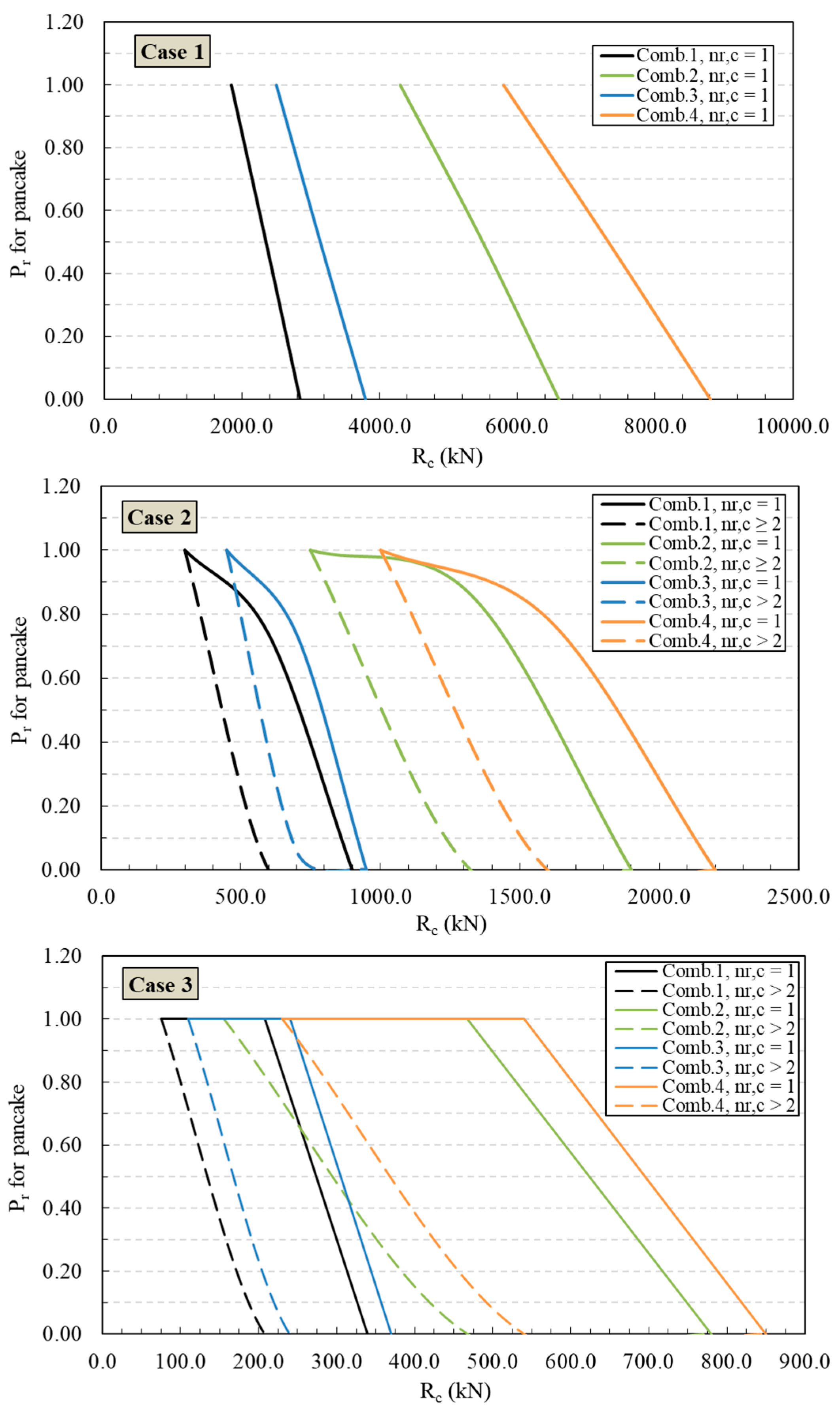
Here, the probability of failure, Pr, for pancake collapse with respect to bending collapse has been estimated for several scenarios, as shown in Figure 8. Three buildings (Figure 4), four combinations (comb. 1–4; see Equations (12)–(15)), and nr,c ≥ 1 have been considered.
In a physical and structural way, the remotion of only one structural column (nr,c = 1) can generate a highly negative impact on the stability of a structure; obviously, for nr,c > 1, the situation could get worse.
As already mentioned, the four combinations consider loadings in the following way: comb. 1 = plastic global pancake vs. elastic bending; comb. 2 = plastic global pancake vs. plastic bending; comb. 3 = elastic global pancake vs. elastic bending; comb. 4 = elastic global pancake vs. plastic bending.
The probability of failure Pr decreases when the strength of the column Rc increases, since Pr is evaluated for pancake collapse, i.e., for the progressive compressive failure of the columns. In this sense, the increase in Rc opposes the instability of the structure, and the probability of bending collapse could increase. In fact, the progressive compressive failure of the columns for pancake collapse occurs when the compressive strength of concrete is set to a small value of fcP = 0.35 MPa, whereas for bending collapse, the value reaches fcB = 35.0 MPa [10,23].
By considering a same Pr value in cases 2–3, Rc for only one removed column (nr,c = 1) is greater than Rc for two or more removed columns (nr,c ≥ 2); in fact, the curve Pr vs. Rc moves to the right. This is because a structure already subject to partial damage should be more vulnerable under further loadings. Thus, a greater Rc could also generate pancake collapse.
Also, the curves that provide a probability of failure for pancake collapse with low Rc correspond to combinations 1 and 3, which refer to the plastic and elastic pancake behaviour, respectively, with respect to elastic bending. This means that the presence of elastic beams can actually influence the pancake collapse of the columns.
In case 3, all curves are closer to a range Rc = 75.0–230.0 kN at Pr ≈ 1.0. This means that Pr values are high for low Rc values independently of the behaviour of the beams and columns.
The curves of combinations 2 and 4 are wider; therefore, Rc must reduce before the structure collapses for nr,c > 2. For theses combinations, the structure could have a large reserve of energy probably due to the plastic behaviour of the beams. In fact, the difference in these combinations only depends on the presence of the plastic columns (comb. 2) and elastic columns (comb. 4).
However, in the name of safety, the Pr results to be used for preliminary structural analyses only refer to nr,c = 1.
It is important to highlight that Equation (21) considers the probability of system failure as a product of individual modes, i.e., the structural system can be defined by a parallel association in active redundancy. This calculated probability corresponds to a lower bound of the system probability; thus, the Pf of the system could be greater than that calculated.
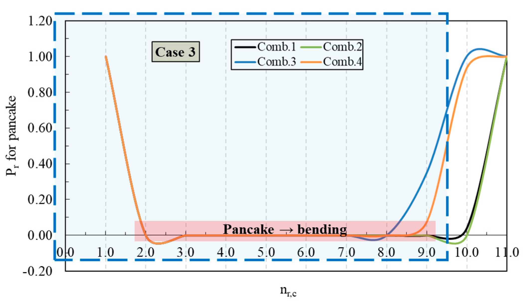
In Figure 9, the Pr is plotted as a function of nr,c for all cases/combinations. It is important to repeat that this model is valid only for the elimination of central columns; therefore, the valid curves are placed in the blue rectangle.
The curves in Figure 9 are consistent with the expected phenomenon up to a certain nr,c, i.e., the decrease in Pr is inversely proportional to nr,c. This is more evident for case 1.
For case 3, it is possible to note that all curves coincide up to nr,c = 7; therefore, the quantity of the columns (thus beams) does not strongly affect this type of structure, probably due to the fact that this structure is formed by several elements; thus, the elimination of a few elements has little impact on its stability. In fact, for nr,c > 7, this effect changes, and the structure behaves like case 2. From a certain nr,c, the Pr curves rapidly increase; thus, the remaining columns must support the loadings until collapse.
The solid red region indicates that pancake collapse does not happen (Pr = 0), and the more predominant phenomenon could be bending collapse. In fact, for a certain value of Rc, mp is higher than mpP, contrary to Equations (12)–(15).
Finally, the first part of the curves (between 1.0 < nr,c < 2.0 for cases 2–3) could represent an initial sign of the instability of the structure; however, for the purpose of Figure 9, it can be neglected.
These considerations are valid since in this model, the “static” plays a more important role that the “mechanics of materials”. In [7,10], it was discussed that after sudden column removals, the plastic capacity of the structural elements decreases collapse loading due to the dissipation of kinetic energy and stress redistributions. If the initial damage brings about the loss of a single column, the structure is considered robust. If the structure undergoes pancake collapse, triggered by the progressive failure of several columns under compression, the damage depends on the fraction of columns that are lost at a storey. Also, the redundancy provided by the beams combined with high levels of stiffness can reduce a mixed vertical–horizontal wide propagation or collapse.

4.2. Dynamic Response of the Buildings

Progressive collapse is a dynamic phenomenon which is correlated with the loss of elements and thus the stiffness of the system [4,35,36]. The failure process proceeds until the stiffness tends to zero (kj → 0 in Section 2.1); thus, the structure collapses.
The stiffness matrix can describe the connections between elements; thus, when the stiffness of the beam–column connection is reliable and there is a mechanism for the transfer of forces between the beam and column, the remaining elements of the structure can withstand and redistribute the external load [18].
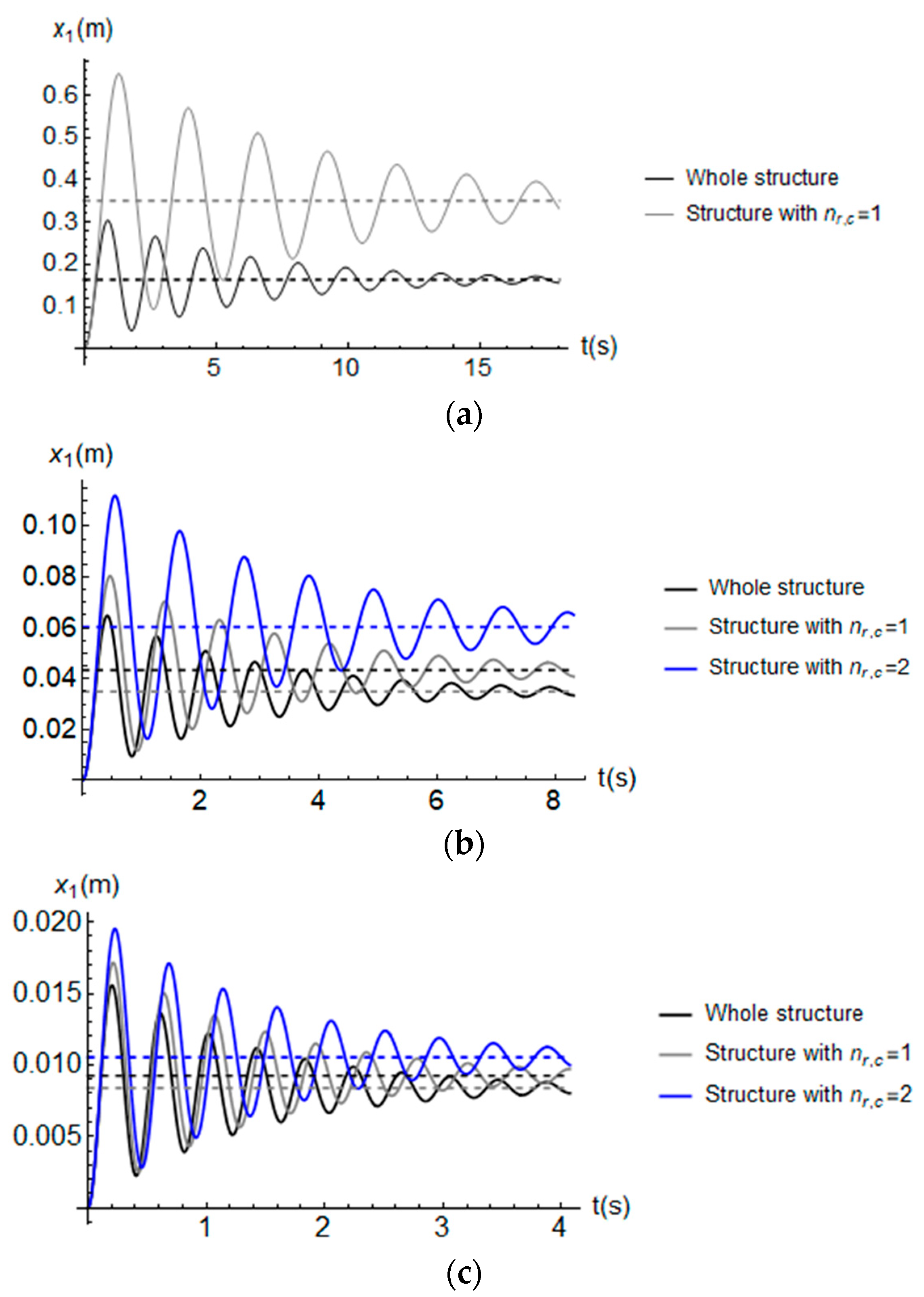
Figure 10 shows the time-history displacements of the first floor of each building, x1(t), where the columns are removed. The analyses have been carried out using Mathematica software [30] by numerically solving Equation (1). The collapse dynamics recorded in these simulations could resemble global pancake collapse [23,35,37].
The values of the buildings are listed in Table 2 (here, proportional values have been used), whereas the adopted acceleration is x ¨ e = 0.20   g and ξ = 5.0%. The global stiffness has been calculated a posteriori by knowing the mass and frequency. The dashed line represents the spectral relative displacement (i.e., x ¨ e /(2 π f)2).
This simple analysis could allow for some aspects to be shown. As expected, the whole structure provides displacements smaller than a structure with one or more columns removed, whereas it is not obvious that for case 2, the response of the whole structure and damaged structure (nr,c = 1) is similar. Also, for case 3, all the responses are similar. In general, the dynamic effects (under collapse) can be ~10.0% greater than the static responses [12].
For case 1, the increase in the displacement in terms of percentage is ~57.0%, whereas for case 3, it ranges between ~11.70% and ~21.0%. This phenomenon shows the impact that removing a few elements has on more simple or articulated buildings.
Finally, it is also possible to quantify the loss of stiffness by considering the initial and damaged stiffness, e.g., in case 1, we obtain a value of ~16.0%, whereas in cases 2 and 3, we have obtained 6.60% and 1.51%, respectively.
In [12], a parameter that indicates the column removal time, Rt, has been proposed. This parameter could correlate the structure collapse with its dynamic behaviour. The general concept was that “the stability of the columns occurs when the column removal tends to zero such that the column removal time has no impact on the response of the structure” [12]. For this, the proposed limit for the critical response is Rt ≤ Tv/100, where Tv is the vertical period of vibration (z-axis) of the structure under the column loss scenario.
Considering the critical interval indicated in [12] (i.e., 0.001 ≤ Rt ≤ 0.02 s), in the present study, we have estimated (with MPMRs in z direction between 67.26 and 89.66%) for case 3, Rt = 0.006 s (for nr,c = 1, 2), and for case 2, Rt = 0.013 s (for nr,c = 2); thus, for both buildings, a “quasi-static” remotion could be dangerous.

5. Conclusions

In this paper, the probability of failure, Pr, for pancake collapse with respect to bending collapse for RC buildings has been estimated. Analytical and numerical analyses have been carried out to study several scenarios. The main conclusions are as follows:
1. Two types of collapse have been considered. The first is called “bending collapse”, where beams collapse for flexure; thus, the columns are stiffer than beams. The second is called “pancake collapse”, where columns are subjected to buckling under compressive forces. The loadings are considered uniformly distributed on the horizontal beams, and the behaviour of the material is elastic or plastic.
This study represents an extension of [10], where only Equation (12) has been carried out in a deterministic way. In this sense, Equations (13)–(15) can be considered new combinations. Also, Equation (22) has been proposed to carry out probabilistic analyses.
2. Probabilistic outputs have been shown in terms of Pr vs. Rc (Figure 8) and Pr vs. nr,c (Figure 9) curves. The probability of failure Pr decreases when the strength of the column Rc increases, since Pr is evaluated for pancake collapse. By considering the same Pr value in cases 2–3, Rc for nr,c = 1 is greater than Rc for nr,c ≥ 2; this is because the structure already subject to partial damage should be more vulnerable under further loadings.
It was noted that the presence of elastic beams can influence the pancake collapse of the columns, and that Pr values are high for low Rc values independently on the behaviour of the beams and columns.
Also, the quantity of the columns does not strongly affect case 3, probably due to the fact that this structure is formed by several elements; thus, the elimination of a few elements has little impact on its stability.
In general, in the name of safety, the Pr results to be used for preliminary structural analyses only refer to nr,c = 1.
3. Dynamic analyses have been carried out. The first floor has been considered where the columns have been removed. For case 1, the increase in the displacement in terms of a percentage is ~57.0%, whereas for case 3, it ranges between ~11.70% and ~21.0%. This phenomenon shows the impact that removing a few elements has on more simple or articulated buildings. Also, a loss of stiffness has been quantified, e.g., in case 1, we obtain a value of ~16.0%, whereas in cases 2 and 3, we have obtained 6.60% and 1.51%, respectively.
The limitations of this study mainly regard the fact that the following has not been considered: (i) the contribution of internal walls or other non-structural elements [2] and (ii) different loading types and their combinations. In this sense, these aspects could represent new challenges for authors.
Finally, this study should provide an incentive to consider progressive collapse during the preliminary and executive design phases of a building. In this way, a structure could comply not only with structural requirements but also with sustainability and safety protocols.

Author Contributions

Conceptualization, E.Z.; methodology, E.Z.; software, E.Z.; validation, C.G.N.; formal analysis, E.Z.; investigation, E.Z. and C.G.N.; writing—original draft preparation, E.Z.; writing—review and editing, E.Z. and C.G.N.; visualization, E.Z. and C.G.N.; supervision, C.G.N.; funding acquisition, C.G.N. All authors have read and agreed to the published version of the manuscript.

Funding

The study was funded by “EDITAL PROPG 69/2023—Auxílio às publicações dos Programas de Pós-graduação da Unesp”, from UNESP-Bauru, Brazil.

Data Availability Statement

All data, models, or code that support the findings of this study are available from the corresponding author upon reasonable request.

Acknowledgments

The first author is grateful for the Foundation for Science and Technology’s support through funding UIDB/04625/2020 from the research unit CERIS (DOI: 10.54499/UIDB/04625/202). The authors also thank the Itecons institute, Portugal, for the Wolfram Mathematica and Robot Structural Analysis licence, and University of Coimbra (UC), Portugal, for paying the rights (when applicable) to completely download all papers outlined in the references.

Conflicts of Interest

The authors declare no conflicts of interest.

References

  1. Pearson, C.; Delatte, N. Roman Point apartment tower collapse and its effect on building codes. J. Perform. Constr. Facil. 2005, 19, 172–177. [Google Scholar] [CrossRef]
  2. Zhang, Q.; Zhao, Y.-G.; Xu, L. Upgrading of reinforced concrete frame using novel detailing technique for progressive collapse prevention. Bull. Earthq. Eng. 2022, 20, 5943–5962. [Google Scholar] [CrossRef]
  3. Chang, D.; Zeng, B.; Huang, L.-J.; Zhou, Z. Investigation on progressive collapse resistance of prestressed concrete frames with infilled walls. Eng. Fail. Anal. 2023, 143, 106866. [Google Scholar] [CrossRef]
  4. Chiaia, B.M.; Masoero, E.; Wittel, F.K.; Herrmann, H.J. DEM simulations of the progressive collapse of framed structures. In Proceedings of the 12th International Conference on Fracture (ICF 2009), Ottawa, ON, Canada, 12–17 July 2009; pp. 1–9. [Google Scholar]
  5. Alshaikh, I.M.; Abu Bakar, B.; Alwesabi, E.A.; Abadel, A.A.; Alghamdi, H.; Altheeb, A.; Tuladhar, R. Progressive collapse behavior of steel fiber-reinforced rubberized concrete frames. J. Build. Eng. 2022, 57, 104920. [Google Scholar] [CrossRef]
  6. De Biagi, V.; Chiaia, B. Complexity and robustness of frame structures. Int. J. Solids Struct. 2013, 50, 3723–3741. [Google Scholar] [CrossRef]
  7. Masoero, E.; Wittel, F.K.; Chiia, B.M.; Herrmann, H.J. Parametric Study of the Progressive Collapse of 2D Framed Structures; 2009; pp. 1–10. [Google Scholar]
  8. EN 1998-4:2006; Eurocode 1: Actions on Structures, Part 1: Basis of Design. European Committee for Standardization (CEN): Brussels, Belgium, 1994.
  9. Carmona, H.A.; Wittel, F.K.; Kun, F.; Herrmann, H.J. Fragmentation processes in impact of spheres. Phys. Rev. E Stat. Nonlinear Soft Matter Phys. 2008, 77, 051302. [Google Scholar] [CrossRef]
  10. Masoero, E.; Darò, P.; Chiaia, B. Progressive collapse of 2D framed structures: An analytical model. Eng. Struct. 2013, 54, 94–102. [Google Scholar] [CrossRef]
  11. Zhang, W.-X.; Li, S.-T.; Wang, X.; Zhang, J.-Y.; Yi, W.-J. Beam torsion effect of monolithic precast concrete beam-column substructures during progressive collapse. Eng. Struct. 2023, 278, 115457. [Google Scholar] [CrossRef]
  12. Stephen, D.; Lam, D.; Forth, J.; Ye, J.; Tsavdaridis, K.D. An evaluation of modelling approaches and column removal time on progressive collapse of building. J. Constr. Steel Res. 2019, 153, 243–253. [Google Scholar] [CrossRef]
  13. Vlassis, A.G.; Izzuddin, B.A.; Elghazouli, A.Y.; Nethercot, D.A. Progressive collapse of multi-storey buildings due to sudden column loss—Part II: Application. Eng. Struct. 2008, 30, 1424–1438. [Google Scholar] [CrossRef]
  14. Masoero, E.; Wittel, F.K.; Herrmann, H.J.; Chiaia, B.M. Progressive Collapse Mechanisms of Brittle and Ductile Framed Structures. J. Eng. Mech. 2010, 136, 987–995. [Google Scholar] [CrossRef]
  15. Levy, M.; Salvatori, M. Perché gli Edifici Cadono; Bombiani: Milan, Italy, 1997; p. 359. [Google Scholar]
  16. Medeot, R. The European Standard on Anti-Seismic Devices, New Zealand Society for Earthquake Engineering (NZSEE). In Proceedings of the 15th World Conference on Seismic Isolation, Energy Dissipation and Active Vibration Control of Structures, Wellington, New Zealand, 27–29 April 2017. [Google Scholar]
  17. Zacchei, E.; Brasil, R. Semi-active tuned mass dampers under combined variable actions of friction forces and external disturbances. Arab. J. Geosci. 2023, 16, 458. [Google Scholar] [CrossRef]
  18. Meng, B.; Zhong, W.; Hao, J.; Song, X.; Tan, Z. Calculation of the resistance of an unequal span steel substructure against progressive collapse based on the component method. Eng. Struct. 2019, 182, 13–28. [Google Scholar] [CrossRef]
  19. Suwondo, R.; Cunningham, L.; Gillie, M.; Bailey, C. Progressive collapse analysis of composite steel frames subject to fire following earthquake. Fire Saf. J. 2019, 103, 49–58. [Google Scholar] [CrossRef]
  20. Rayegani, A.; Nouri, G. Application of Smart Dampers for Prevention of Seismic Pounding in Isolated Structures Subjected to Near-fault Earthquakes. J. Earthq. Eng. 2022, 26, 4069–4084. [Google Scholar] [CrossRef]
  21. Rayegani, A.; Nouri, G. Seismic collapse probability and life cycle cost assessment of isolated structures subjected to pounding with smart hybrid isolation system using a modified fuzzy based controller. Structures 2022, 44, 30–41. [Google Scholar] [CrossRef]
  22. Jiménez-Fabián, R.; Alvarez-Icaza, L. An adaptive observer for a shear building with an energy-dissipation device. Control. Eng. Pract. 2010, 18, 331–338. [Google Scholar] [CrossRef]
  23. Masoero, E.; Wittel, F.K.; Herrmann, H.J.; Chiaia, B.M. Hierarchical Structures for a Robustness-Oriented Capacity Design. J. Eng. Mech. 2012, 138, 1339–1347. [Google Scholar] [CrossRef]
  24. Clough, R.W.; Penzien, J. Dynamics of Structures, 1st ed.; McGraw-Hill: New York, NY, USA, 1976; 3a ed., 2003; p. 752. [Google Scholar]
  25. AutoCAD, version 2010; Autodesk, Inc.: San Francisco, CA, USA, 2010.
  26. Shirinzadeh, M.; Haghollahi, A. Rehabilitation in Simple Steel Connections against Progressive Collapse due to Column Removal. KSCE J. Civ. Eng. 2019, 23, 737–743. [Google Scholar] [CrossRef]
  27. Quiel, S.E.; Naito, C.J.; Fallon, C.T. A non-emulative moment connection for progressive collapse resistance in precast concrete building frames. Eng. Struct. 2019, 179, 174–188. [Google Scholar] [CrossRef]
  28. Robot Structural Analysis, Professional 2020, Software, version 33.0.0.6930 (x64); Autodesk Inc.: San Francisco, CA, USA, 2019.
  29. Zacchei, E.; Lyra, P.H.C. Recalibration of low seismic excitations in Brazil through probabilistic and deterministic analyses: Application for shear buildings structures. Struct. Concr. 2022, 24, 937–955. [Google Scholar] [CrossRef]
  30. Wolfram Mathematica 12; Software Version Number 12.0; Wolfram Research, Inc.: Champaign, IL, USA, 2019.
  31. Zacchei, E.; Nogueira, C.G. 2D/3D Numerical Analyses of Corrosion Initiation in RC Structures Accounting Fluctuations of Chloride Ions by External Actions. KSCE J. Civ. Eng. 2021, 25, 2105–2120. [Google Scholar] [CrossRef]
  32. Wang, Z.; Broccardo, M.; Song, J. Hamiltonian Monte Carlo methods for Subset Simulation in reliability analysis. Struct. Saf. 2019, 76, 51–67. [Google Scholar] [CrossRef]
  33. Nogueira, C.G.; Yoshio, L.; Zacchei, E. Deterministic and probabilistic approaches for corrosion in RC structures: A direct proposed model to total service life predictions. Case Stud. Constr. Mater. 2023, 18, e01913. [Google Scholar] [CrossRef]
  34. Nogueira, C.G.; Leonel, E.D.; Coda, H.B. Probabilistic failure modelling of reinforced concrete structures subjected to chloride penetration. Int. J. Adv. Struct. Eng. 2012, 4, 10. [Google Scholar] [CrossRef]
  35. Lin, S.-C.; Yang, B.; Kang, S.-B.; Xu, S.-Q. A new method for progressive collapse analysis of steel frames. J. Constr. Steel Res. 2019, 153, 71–84. [Google Scholar] [CrossRef]
  36. Luccioni, B.; Ambrosini, R.; Danesi, R. Analysis of building collapse under blast loads. Eng. Struct. 2004, 26, 63–71. [Google Scholar] [CrossRef]
  37. Li, P.; Liang, C. Risk Analysis for Cascade Reservoirs Collapse Based on Bayesian Networks under the Combined Action of Flood and Landslide Surge. Math. Probl. Eng. 2016, 2016, 2903935. [Google Scholar] [CrossRef]
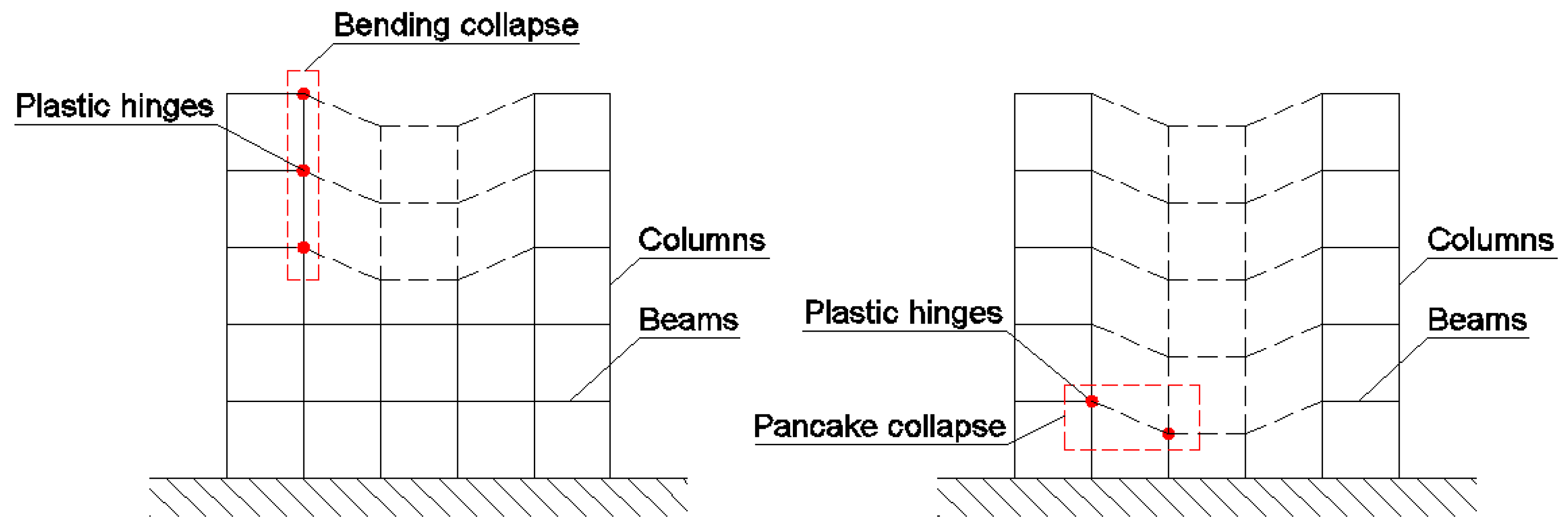
Figure 1. Illustration of the studied collapses for a 2D building [25].
Buildings 14 01948 g001
Figure 2. Sequences of the collapse analysis (the conditions studied in this paper are in blue).
Buildings 14 01948 g002
Figure 3. Scheme of the building and its removed parts [25].
Buildings 14 01948 g003
Figure 4. FEM model for (a) case 1, (b) case 2, (c) case 3 [28]; (d) structural dynamic scheme valid for all cases [25].
Buildings 14 01948 g004
Figure 5. PDF of By ± σ and Rc ± σ for the three cases (see Table 3) and example of 3D MCS (below right).
Buildings 14 01948 g005
Figure 6. Illustration of (a) LS functions (adapted from [34]) and (b) example of 3D PDF.
Buildings 14 01948 g006
Figure 7. General methodology of the analyses (new contributions are in green).
Buildings 14 01948 g007
Figure 8. Probability of collapse for pancake, Pr, in function of Rc values (all cases and combinations).
Buildings 14 01948 g008
Figure 9. Probability of collapse for pancake Pr vs. nr,c (valid curves are placed in the blue rectangle).
Buildings 14 01948 g009aBuildings 14 01948 g009b
Figure 10. Time-history displacements of the first floor for (a) case 1, (b) case 2, (c) case 3.
Buildings 14 01948 g010
Table 1. Deterministic data for the three studied buildings.
ParameterValue for Each Case
Case 1Case 2Case 3
Number of columns, nc (-)3.06.012.0
Number of storeys, ns (-)2.05.011.0
Length of the beam, L (m) a20.09.04.0
Height of the column, H (m) a16.506.503.0
Concrete mass density, γc (kN/m3)25.0
a The beams and columns are dimensions of B 30.0 × 50.0 cm and C 45.0 × 45.0 cm, respectively.
Table 2. Modal analyses by FEM model [28].
CaseStructural Frequency
Whole Structure nr,c = 1.0nr,c = 2.0
Case 10.37 Hz (67.62 × 10³ kg)0.32 Hz (63.44 × 10³ kg)-
Case 20.84 Hz (173.31 × 10³ kg)0.83 Hz (171.67 × 10³ kg)0.79 Hz (170.02 × 10³ kg)
Case 31.79 Hz (373.06 × 10³ kg)1.79 Hz (372.30 × 10³ kg)1.77 Hz (371.54 × 10³ kg)
Note: In brackets, the mass of the building is indicated.
Table 3. Probabilistic results (By values refer to all combinations, whereas Rc values refer only to combination 1).
ParameterCase 1Case 2Case 3
Moment yield threshold of the beam, Byμ (kN × m) a9137.17580.1853.97
±σ (kN × m) 1057.4067.036.20
CV (%)11.5711.5511.48
Compressive strength of the column, Rcμ (kN)2357.91597.46206.34
±σ (kN)568.88346.59154.43
CV (%)24.1358.0174.84
a Values similar to those used in [10].
Disclaimer/Publisher’s Note: The statements, opinions and data contained in all publications are solely those of the individual author(s) and contributor(s) and not of MDPI and/or the editor(s). MDPI and/or the editor(s) disclaim responsibility for any injury to people or property resulting from any ideas, methods, instructions or products referred to in the content.