Article

Investigating the Influence of Oil Shale Ash and Basalt Composite Fibres on the Interfacial Transition Zone in Concrete

by
Iveta Nováková
1,*,
Ashfaque Ahmed Jhatial
1,
Sofija Kekez
1,
Eirik Gjerløw
1,
Volodymyr Gulik
2,3,
Karunamoorthy Rengasamy Kannathasan
4,
Mindaugas Vaišnoras
5 and
Andrejs Krasnikovs
4
1
Department of Building, Energy and Material Technology, Faculty of Engineering and Technology, The Arctic University of Norway, Lodve Langesgate 2, N-8514 Narvik, Norway
2
Institute of Physics, University of Tartu, W. Ostwaldi 1, 50411 Tartu, Estonia
3
Institute for Safety Problems of Nuclear Power Plants, 12 Lysogirska St., 03028 Kyiv, Ukraine
4
Department of Theoretical Mechanics and Strength of Material, Riga Technical University, Ķīpsalas Iela 6a, Centra Rajons, LV-1048 Riga, Latvia
5
Lithuanian Energy Institute, Breslaujos St. 3, LT-44403 Kaunas, Lithuania
*
Author to whom correspondence should be addressed.
Buildings 2024, 14(7), 1952; https://doi.org/10.3390/buildings14071952
Submission received: 19 May 2024 / Revised: 21 June 2024 / Accepted: 23 June 2024 / Published: 27 June 2024

Abstract

:
The interfacial transition zone (ITZ) is the weakest phase in concrete, characterised by higher porosity and being prone to microcrack formation. Additionally, the ITZ is created when dispersed fibre reinforcement is present. Although fibres improve flexural strength, they can negatively impact other properties. This research investigates the ITZ of fibre-reinforced concrete where macro-basalt fibres (BFs) and oil shale ash (OSA), as an SCM, were used with the aim of modifying the properties of concrete, enhancing the ITZ, and reducing its carbon footprint. Six different concrete mixes with OSA doses between 10% and 30% and a constant BF dose of 8.0 kg per 1 m3 of concrete were prepared and tested. The ITZ was analysed with SEM images and verified through its mechanical properties. The results showed that the presence of OSA improved bonding and densified the microstructure of the paste, especially in the ITZ, resulting in a nearly constant flexural strength at up to a 20% replacement and only a 6.7% decrease in compressive strength while reducing the global warming potential by 19.24 kg CO2 equivalent in the mix with 10% OSA replacement. Higher replacement ratios had a negative impact on the mechanical properties, as the OSA had not reacted entirely and served partly as an inert filler.

1. Introduction

Concrete, the most widely used construction material, continually undergoes improvements to enhance its strength, durability, and overall performance [1]. One significant area of focus is the interfacial transition zone (ITZ), which forms between the paste and aggregates [2]. The paste–aggregate ITZ is considered the weakest phase of concrete due to the higher porosity and larger crystalline phases in this zone compared with the bulk paste. It is also the zone where the cracks initiate, further propagating and damaging the concrete when the maximum loading is reached. Therefore, microcracking, which frequently initiates and propagates within the ITZ, leads to the perception that the ITZ is the weakest phase in concrete [3].
Fibres have gained importance as a valuable addition to concrete mixtures since they govern the flexural strength and other mechanical characteristics of the concrete [4]. Fibres enhance bonds by mechanically interlocking the matrix and aggregates, reducing the potential for debonding and improving load transfer across the ITZ [5]. Moreover, fibres act as reinforcement within concrete, mitigating crack propagation and improving the overall durability of the structure [6]. Despite the positive influence of fibres, a fibre–paste ITZ is formed similar to the paste–aggregate ITZ [7]. A study on high-performance fibre-reinforced concrete revealed similar hardness values in the ITZ between the aggregate and the paste as in the ITZ between the steel fibres and the paste [8]. The formation of the ITZ occurs as small binder particles exhibit a lower packing density when they encounter a large surface area, such as that of fibres, creating a “wall effect”. This leads to increased porosity and an increase in the frequency of phases with low moduli, including pores and low-density calcium silicate hydrate (CSH) near the fibres. Furthermore, an elevated content of well-grown crystals of calcium hydroxide (CH) is a distinguishing characteristic of the ITZ. The wall effect can be eliminated through several mixing modifications. These include w/c ratio reduction and the use of a well-graded binder with a combination of cement and microsilica or other SCMs.
The incorporation of supplementary cementitious materials (SCMs) has been widely explored to reduce the CO2 footprint of concrete, address the weakness of the ITZ, and further optimise it. SCMs such as fly ash, slag, silica fume, and metakaolin possess particle sizes and chemical compositions that can enhance packing density and provide additional reactivity delay within the ITZ [9]. By filling voids, providing additional cementitious gel, and optimising the curing conditions, SCMs reduce porosity and enhance the ITZ’s strength and durability.
Fibres are vital for enhancing concrete’s performance, providing benefits such as improved crack control, durability, and structural integrity [10]. They distribute stresses, reducing crack propagation and brittle failure. Fibres enhance tensile strength, toughness, and resistance to impact, cyclic loading, and shrinkage cracking [10]. With their versatility in form and material, fibres offer an effective way of extending service life and ensuring the long-term durability of concrete structures.
This article investigates the synergistic effects of macro-basalt fibres (BFs) and oil shale ash (OSA) on concrete properties, with a focus on the fibre–paste ITZ of the concrete. The targeted use of designed concrete types is carried out in hazardous waste management, in particular, storage packaging for low-level radioactive waste (LRW), where low-strength concrete is utilised for the encapsulation of LRW, which is further placed in larger containers. A thorough understanding of the ITZ is essential for ensuring the radiation shielding performance of the complete packaging. This experimental investigation uses OSA as an SCM with varying percentages of cement replacement, with a constant amount of BFs in the concrete mix, and analyses the microstructure of the mixtures. To this end, the mechanical properties of fresh and hardened concrete mixes containing BFs and OSA are investigated in correlation with the observed SEM images of the samples’ cross-sections. Furthermore, the environmental benefits of the application of OSA in concrete are highlighted via the calculation of the global warming potential.

1.1. Basalt Fibres

BFs have emerged as promising fibrous reinforcement materials for concrete due to their exceptional mechanical properties and resistance to chemical degradation [11].
The manufacturing process for BFs includes melting basalt volcanic rocks at 1400–1450 °C and extrusion through small nozzles to produce continuous filaments with 7–20 μm diameters. The three main manufacturing techniques for BFs are centrifugal blowing, centrifugal multirolling, and die-blowing. Even so, similar to the production of glass fibres, the BF production process is more environmentally friendly, energy-efficient, and cost-effective. This joint impact is created because glass fibre production involves using additives [12], such as boric acid, and causes direct emissions of heavy metals, such as SO2 and NOx [13], which do not happen during BF production. BFs are produced as monofilaments with diameters in the range of 7–20 μm. They can be used as microfibres or further processed into bundles and fabrics. Basalt microfibres used for concrete are produced from bundles of various numbers of filaments and coated in resin, which provides additional protection and improved alkali resistivity. The helical structure of BFs improves their cohesion and helps anchor the fibres in the concrete matrix. BFs are environmentally safe and non-toxic and possess high stability and resistance to low temperatures [14].
A study was conducted by Biradar et al. [15] using various BF proportions (0.1%, 0.3%, and 0.5% of the total concrete volume) in M40-grade concrete, in which it was observed that although the increase in fibre content reduced the workability, the mechanical strength increased significantly. A trend was noticed with the addition of BFs; the ratios of strengths (compressive and bending) compared to the control concrete were significantly higher after 3 days and gradually reduced as the concrete aged. Tests revealed that a 0.3% BF content gave rise to the highest strengths, with values of 48.63 MPa, 4.73 MPa, and 7.32 MPa, resulting in strength ratios of 9.82%, 36.70%, and 18.83% compared to the control sample for the compressive, tensile, and flexural strengths after 28 days, respectively. Arslan [16] conducted a comparative study between BFs and chopped glass fibres, with four fibre contents (0.5, 1, 2, and 3 kg per m3 of concrete). The diameter varied from 13 to 20 µm for the BFs and 10 to 17 µm for the glass fibres, while the length was kept constant at 24 mm for both types of fibres. The results showed that the addition of fibres, regardless of the type, contributed to improvements in mechanical strength compared to the reference concrete. The compressive strength, splitting tensile strength, flexural strength, fracture energy, and modulus of elasticity increased with the inclusion of fibres. It was observed that for the glass fibres, the optimum fibre content was 1 kg per m3, with increases of 4.20%, 9.32%, and 25.92% compared to the control concrete. As for the BFs, the highest compressive strength (7.26% higher than the control concrete) was observed with 3 kg per m3 fibre content, while the splitting tensile and flexural strengths were lower than those observed with the glass fibres. Branston et al. [17] evaluated the mechanical behaviour of basalt fibre-reinforced concrete. Basalt fibres were introduced in the concrete as bundled fibres and as minibars. The study showed that higher fibre dosages (more than 12 kg/m3 of bundles and 40 kg/m3 of minibars) led to difficulties in handling, placing, and consolidating fresh concrete. However, it should be noted that the first-crack strength increased with increasing fibre dosage. In a study by Meyyappan et al. [4], BFs were incorporated into concrete in concentrations of 0.5, 1, 1.5, 2, 2.5, and 3 vol.% and tested for compressive and split tensile strengths. The results indicated that 1 vol.% of BFs showed an optimal enhancement of strength properties, while a further increase in the volume fraction of BFs gave rise to a decreasing trend in a drastic manner. All the listed results lead to the common conclusion that an excess of BFs impacts the overall concrete performance negatively, which can be explained by the significant enlargement of the ITZ in concrete. Individual fibres, regardless of their dimensions or material, introduce an additional ITZ between fibres and paste with similar weaknesses to the ITZ between aggregates and paste. Understanding the properties of the fibre ITZ can lead to better optimisation of fibre dosage and consequent concrete performance towards defined requirements.

1.2. Interfacial Transition Zone (ITZ) of Concrete

In cement-based composites, each aggregate is surrounded by an ITZ varying from 10 µm to 50 µm [18] in thickness, based on its origin. Due to the way it is formed, the ITZ is not a defined zone but a region which can move or vary in thickness [2]. The ITZ is formed around aggregate grains during concrete curing, which implies that the water content in this area dictates ITZ formation. Vibrating fresh concrete moves the aggregate grains and forms areas with a much higher w/c ratio. Furthermore, aggregates express high initial sorption, subsequently releasing absorbed water. Since aggregates have higher levels of water absorption, they can change the conditions in the ITZ, leading to the formation of different hydration products. Also, it must be considered that some cement particles or SCMs may show delayed hydration in the space between large crystals of CH formed in the surplus water.
Compared to bulk paste regions, the ITZ is structurally inferior [19] due to its higher average porosity, CH content, and ettringite content (CAS̅H), along with a lower concentration of cement particles, such as low-density CSH, as shown in Figure 1. The ITZ is often believed to facilitate the ingress of harmful substances such as moisture, chemicals, or aggressive agents into concrete, as its increased porosity suggests higher local transport properties compared to the bulk paste [19]. In concrete types with a high aggregate content, adjacent ITZs can overlap and interconnect, creating a continuous porous pathway that spans the sample and acts as a shortcut for the penetration of harmful agents from the surface into the concrete’s inner section.
While the distinction between the ITZ and bulk paste is evident, the precise mechanism by which the ITZ operates remains elusive since evaluating the ITZ’s mechanical properties within the overall concrete structure proves to be challenging. In-depth analyses conducted by Hashin and Monteiro [21] revealed that the elastic modulus of the ITZ is approximately 50% lower than that of the bulk paste, making it more susceptible to cracking. This formation of cracks leads to a reduction in the overall strength of the concrete. Hence, fibre reinforcement is beneficial, as the main feature of fibres is to prevent crack formations and their further propagation [22,23]. However, another complexity occurs because the inclusion of fibres in the concrete matrix leads to the development of additional ITZs between the fibres and the paste.

1.3. Fibre–Paste Interfacial Transition Zone

The addition of fibres in concrete has been ongoing due to their ability to control cracks and increase the toughness of concrete [10]; however, they introduce additional ITZs and modify the microstructure of concrete. As shown in Figure 2, each fibre is encircled by an ITZ, which exhibits similar microstructure to the paste–aggregate ITZ and is chemically and mechanically distinct from the bulk paste [4]. Initially, a fibre ITZ was observed when concrete was reinforced with macrofibres like steel fibres [24,25]. However, it has been reported that a similar fibre ITZ also exists on microfibres, such as polyethylene fibres [25]. Furthermore, in terms of microstructure, both the paste-aggregate ITZ and the fibre–paste ITZ are quite similar, as both have high porosity with higher proportions of CH [4,26,27]. In a fresh state, local bleeding around the fibres causes the dispersion of cement or SCMs in an abundance of water, thus providing space for the growth of larger crystals of CH, ettringite, and low-density CSH. Bentur and Mindess [28] determined the depth of the ITZ to be between 20 and 50 μm using scanning electron microscope observations, while Li and Stang [29] found the depth to be between 40 and 70 μm.
Numerous studies have been conducted to characterise the microstructure/microstructural gradients of the ITZ in concrete using different tools, such as scanning electron microscopy (SEM) and energy-dispersive X-rays (EDXs) [31]. From the SEM images [16] in Figure 3a, a well-bonded, partially coated ITZ between the BFs and paste is visible, which contributes to increased flexural and splitting tensile strengths. Furthermore, it was observed that the high tensile strength of BFs could be the reason for the fibre rupture restriction. The glass fibres (Figure 3b), on the other hand, exhibited agglomeration tendencies, suggesting the need for careful production to prevent agglomeration in glass fibre-reinforced concrete mixtures. No agglomeration was observed in the BF-reinforced concrete mixtures [16].
Since each fibre has its own ITZ, with an excessive number of fibres or a non-uniform distribution of fibres, the fibre ITZs have the potential to overlap and interconnect, forming a continuous porous pathway that extends across the sample. This pathway could allow for the penetration of aggressive agents into the inner sections (bulk paste) of the concrete, impacting its durability and thus rendering the fibres more harmful to the concrete than beneficial.
The weakness of the fibre ITZs could potentially be addressed by incorporating a suitable SCM. SCMs undergo pozzolanic or latent hydraulic reactions with delays, thus reducing the CH content and promoting the formation of denser hydration products in the ITZs. The fine particle sizes of SCMs improve the packing density, which reduces the porosity. SCMs also contribute to improved delayed curing and hydration, enhancing the bond strength in available spaces (pores, spaces between large crystals or CSH layers), predominantly in the ITZs. These changes are assumed to contribute to creating a more compact and refined ITZ, leading to improved durability and reduced permeability in concrete structures. Oil shale ash is one such SCM which has the potential to induce changes in the microstructure of fibre–paste ITZs.

1.4. Oil Shale Ash (OSA)

Oil shale is a sedimentary rock containing solid organic content that can produce liquid oil-like hydrocarbons when heated. It is found in numerous deposits worldwide, but only a few countries have economically viable deposits. The extraction of shale oil from the oil shale is still under development, with the global supply estimated at 5 trillion barrels. The extraction process generates significant amounts of waste fly ash, which is known as OSA. OSA is reused in various applications, such as in agriculture [32] (it helps increase the yield through the neutralisation of acidic soils and improves arable and grassland soils) and the construction industry [33] (as a cementitious material or admixture for the mass stabilisation of soft soils and for groundwork for roads, railways, and pipelines), as well as being used as a filler in the plastics industry [34]. Furthermore, it has been found [35] that calcium extracted from OSA can form calcium carbonite after CO2 is injected into its solution. This calcium carbonite is then used in the paper and plastics industries [35]. The utilisation of OSA as a cementitious material is currently limited, but it has high potential as it can partially replace cement and thus reduce the carbon footprint of concrete.
Liu et al. [36] conducted an extensive study on calcinated OSA residue used as an SCM in doses varying from 10% to 50% by wt. of cement. The results showed that the OSA residue contained kaolinite, montmorillonite, and illite, which were activated by calcining at 500, 600, and 700 °C to improve pozzolanic reactivity. It was determined that the 10% OSA residue calcined at 600 °C was optimal, as it increased the compressive strength by 8% (3 days) and 11% (28 days). Another study was conducted to explore the feasibility of utilising OSA (0%, 10%, 20%, 30%, and 40%) as an SCM in roller-compacted concrete [37]. The results demonstrated that the mechanical properties of roller-compacted concrete mixes decreased with increasing OSA content but still met the compressive stress requirements according to the American Concrete Institute’s standards. Based on these findings, incorporating OSA at up to a 30% replacement level in roller-compacted concrete production is feasible, providing a potential solution for utilising abundant OSA deposits in Jordan while maintaining acceptable concrete performance. Murad et al. [38] investigated the feasibility of using Jordanian OSA (30%, 50%, and 100%) as a partial or complete replacement for cement. The concrete samples were exposed to a temperature of 720 °C for 2 h to evaluate the impact of heat on the mechanical properties of OSA concrete. The results revealed that OSA can be effectively recycled in low-strength concrete, with the optimal replacement percentage found to be 30% of the cement weight. The addition of 30% OSA as a partial replacement for cement increased the flexural strength by 50% but led to decreases in the compressive and tensile strengths of 33% and 44%, respectively. The mineralogy of OSA can vary based on its origin, for example, the addition of biomass in combustion. Kalpokaitė-Dičkuvienė et al. [39] reported that the addition of biomass during combustion reduces the anhydrite content by more than 50% in comparison to pure OSA combustion. A higher content of anhydrite resulted in a higher formation of ettringite in the test paste. Furthermore, the porosity of OSA is greatly dependent on its origin.
This paper presents a research study that focuses on the use of OSA in fibre concrete. The authors are motivated by the vision of reducing abundant deposits of OSA in Estonia through its utilisation in fibre concrete used in hazardous waste management. This investigation uses the hypothesis that the ITZ can be densified through the delayed formation of additional hydration products formed by pozzolanic reactions between OSA and existing compounds in the ITZ. This study serves as a preparatory work for the utilisation of special basalt boron fibres with enhanced neutron shielding properties. A compact fibre–paste ITZ would ensure the full potential of basalt boron fibres is met.

2. Methodology

For the analyses of the fibre–paste ITZ, concrete mixes were prepared with a constant fibre dose of 8.0 kg per m3 of concrete and a variable dose of OSA, ranging from 10 to 30% by cement weight. The materials used were Portland limestone cement (PLC) CEM II/A-LL 42.5 N from Schwenk cement Latvia, dolomite powder and fine aggregates obtained from Saulkane, Latvia, and OSA obtained from Eesti Power Plant, Estonia, where oil shale is burned without any addition of biomass. The chemical composition of the OSA was determined on Li2B4O7-LiBO2-LiI + sample-fused glasses through X-ray fluorescence spectroscopy (XRF) using a Rigaku Primus II spectrometer and PLC provided by the producer, and it is shown in Table 1. Though OSA has been classified as a pozzolanic material in the literature, the chemical composition of this OSA indicates otherwise, as it is 4% short of pozzolanic oxides to fulfil the requirement to be classed as a class C pozzolan material according to ASTM C618-22 [40]. The average D50 particle size of the OSA was 26.9 μm. This type of OSA has a high content of anhydrite, approx. 14.57 wt%, and approx. 11.61 wt% of amorphous phase [39]. As OSA is waste, its properties, such as mineralogy and particle size distribution, can vary from batch to batch.
The coated–chopped composite BFs from Deutsche Basalt Faser GmbH have a rectangular cross-section with average dimensions of 0.55 mm to 0.36 mm and are composed of filaments with a diameter of 13 ± 1 μm, a length of 24 mm, and a density of 1.9 g/cm3. The properties of the OSA and BFs are presented in Figure 4.
A reference concrete mix (C) without OSA was designed with a target compressive strength of 15 MPa after 28 days. Mixes with OSA in replacement ratios of 10, 15, 20, 25, and 30% by weight of cement were produced in a laboratory mixer. The proportions of all six mixes are given in Table 2, and they were designed in such a manner as to provide enough paste for fibre dispersion and anchoring. Furthermore, the concrete mixes were designed to be used for low-level hazardous waste storage, where they serve as filling and shielding agents. Those concrete types commonly have low strength and workable consistency, so the low-level hazardous waste can be blended and poured into a steel drum.
The proportions of PLC and OSA change in relation to the particle size distribution (PSD) of the individual mixes. The suitable proportion of individual materials can influence the packing density, and therefore, the PSDs of the individual powder materials, except microsilica, were analysed, and the grading curves are provided in Figure 5. Figure 5 shows that with increasing content of OSA, the overall PSD of the individual mixes changes only slightly. Since OSA shows a PSD of a similar order of magnitude as cement, it is expected that it would directly replace cement in terms of particle packing.
The flow of the experimental work is shown in Figure 6. The mixing of concrete was carried out in a tilting drum mixer. The required materials were pre-weighted as per mix proportion and mixed as follows: (1) half of the cement, powders, and aggregates were dry mixed; (2) half of the water was poured into the mixer; (3) the remaining cement, powders, and aggregates were added; (4) the remaining water and SP were then added to reach the targeted workability; and (5) BFs were spread into the rotating mixer so that a uniform distribution of fibres was achieved. The fresh concrete’s consistency was measured by a slump test with a target slump of 220–250 mm. The concrete was cast into moulds and, after 24 h of initial curing under cover, moved to the water storage tank. Compressive and flexural strengths were evaluated on the 28-day-old samples. To understand the fibre–paste ITZ of the concrete, a microstructural analysis was conducted using SEM.

3. Results and Discussion

The obtained results are first discussed on the microscale through a detailed investigation of fibre–paste ITZ via SEM images. An assessment of the mechanical performance of the concrete then follows, showing the results of the slump as well as compression and bending tests. The discussion is concluded with the results of the global warming potential of the concrete mixes with OSA replacement, which shows the additional benefit of using this SCM.

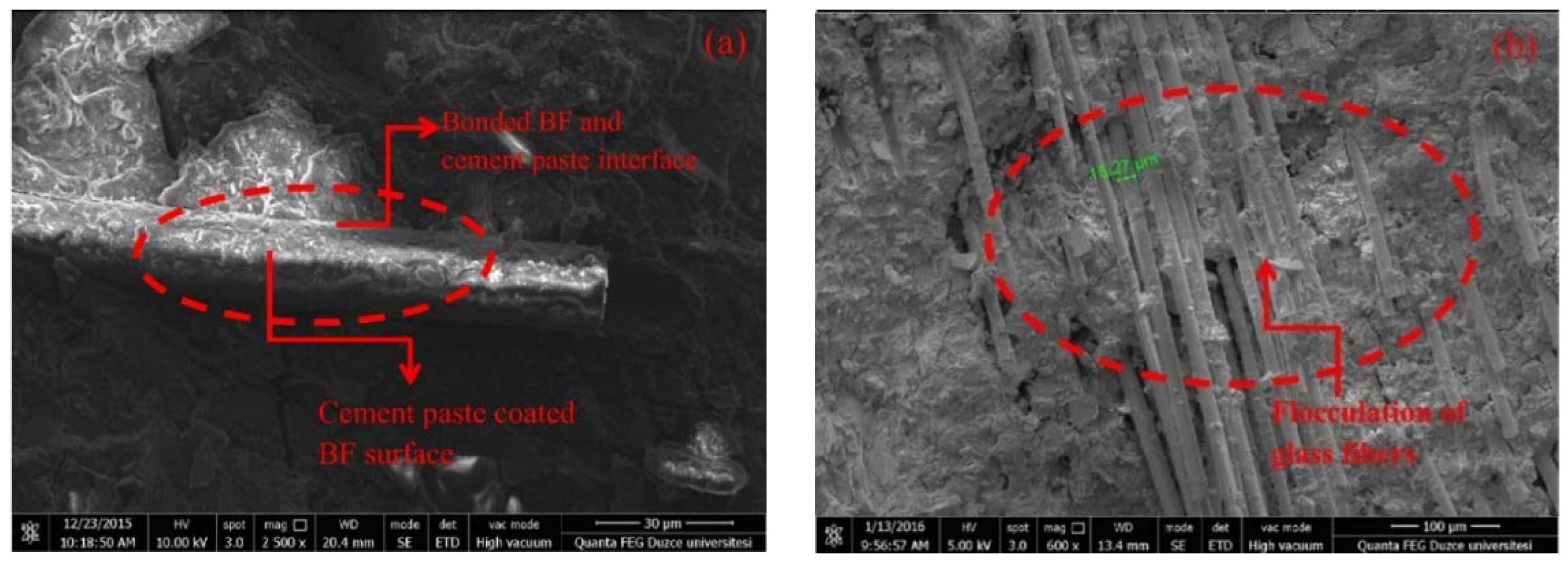
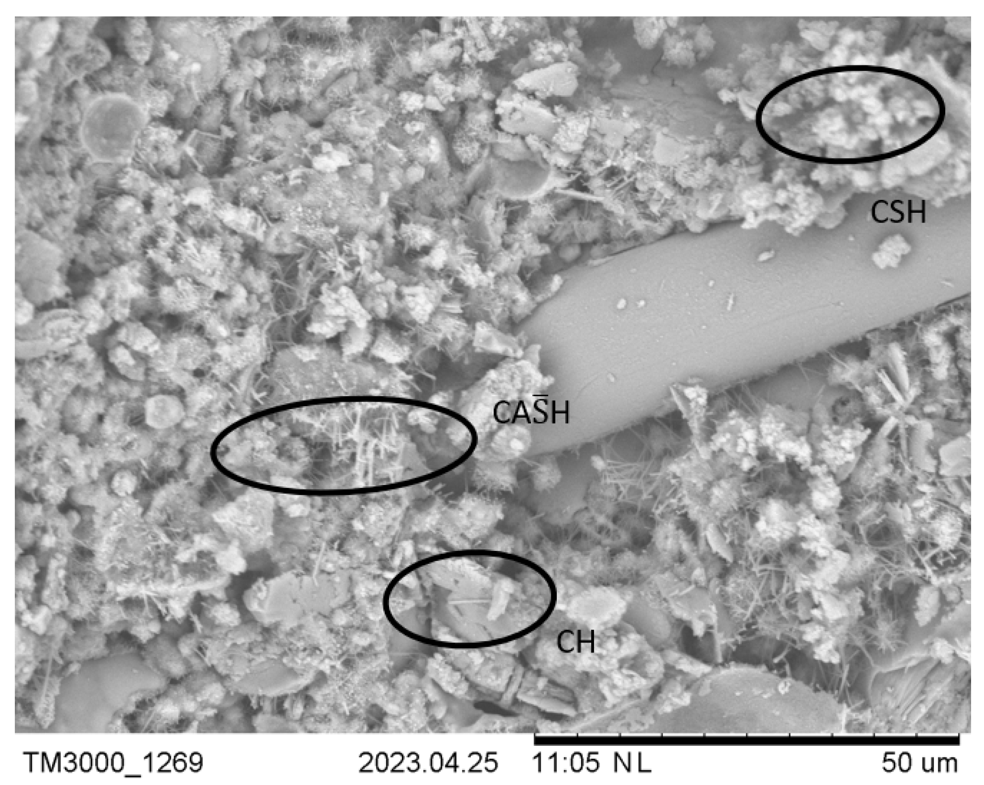
3.1. Analysis of Fibre–Paste ITZ

The SEM images in Figure 7 show that several basalt filaments are embedded in the concrete matrix, and it seems that the resin of the BFs is disrupted. Each individual BF has its own ITZ surrounding it [2,42], with the diameter of each BF’s own ITZ being difficult to determine. Nonetheless, the individual ITZs of the fibres contribute to the overall fibre–paste ITZ network by combining and overlapping with each other. When the destruction of the paste begins due to external loading, the fibres provide strength to the paste to a certain extent. The SEM sample is cut out of a larger sample with the aim of having the BFs visible on the analysed surface. Some fibres can fracture due to the sample preparation, as can be observed in Figure 7. Furthermore, there are visible gaps between fibres where neither the resin nor cementitious paste penetrated and poorly formed binder hydration products between and around the individual basalt filaments.
From Figure 7, it is visible that the resin coating of the individual basalt microfibres is damaged, and the binder of the analysed concrete is directly in contact with the basalt microfibres where the fibre ITZs are formed. Upon closer examination, the main hydration products, CSH, CH, and ettringite, are present in the fibre ITZs, as seen in Figure 7 and Figure 8. The OSA used in this study contains 5.45 wt.% of SO3, as determined by XRF analyses, and XRD showed that it contains 14.5% anhydrite [39], and therefore, more ettringite and formations containing sulphur are formed, especially in the ITZs with greater amounts of water and space available. According to the chemical composition given in Table 1, the weight percentage of SO3 in the OSA is slightly higher than that required for SCMs according to EN 450-1 [43] and ASTM C618-22 [40,44]. Ettringite formation is dependent on the presence of sufficient sulphate ions in the solution. Once gypsum is exhausted, ettringite will continue to react with the remaining C3A, resulting in the formation of monosulphoaluminate hydrate [45]. Due to the excessive presence of sulphur from the OSA, not all ettringite is converted into monosulphoaluminate hydrate; see Figure 8.
High-density CSH is predominantly present in the bulk paste, and low-density CSH with a larger distance between layers filled with water molecules is likely to be present in the ITZs. Additional CSH is formed by the reaction between the alkaline binder and silicates from the BFs that are not sufficiently coated by the macro-BF resin. The BF surface indicates some level of interaction and chemical bonding between the fibres and the paste [46], leading to improved fibre–paste interface properties. It should be noted that the CSH products on the surface of the BFs could be attributed to a phenomenon called secondary deposition or precipitation. Secondary deposition may occur if the silica-rich BFs lose their coating and are directly exposed to the alkaline environment of the cement paste, instigating a reaction which results in the formation of a thin layer of CSH on the fibre surface [47,48,49]. The described phenomena can be observed in the SEM image in Figure 9. However, if the reaction continues, it could completely degrade the BFs and compromise the benefits of BF application [50].

3.2. Mechanical Properties of Concrete Mixtures

A detailed analysis of the concrete paste containing exclusively cement and OSA led to the conclusion to use additional SCMs, particularly microsilica. Furthermore, dolomite powder was used to provide a higher volume of paste to facilitate BFs. As this testing served as a pre-study for the utilisation of BFs, lower-strength concrete mixes were designed and tested. The fresh concrete’s workability and the hardened concrete’s properties, namely compressive and flexural strengths, are given in Table 3.
The workability of the prepared mixes ranged from 180 to 230 mm, with most of the mixes having a slump at 220 mm. All the mixes except OSA20 satisfied the target slump of 220–250 mm. Sufficient workability was ensured by a water/binder ratio of 0.47 and a rather high SP dose of 6.36 kg per m3. The total binder weight was 481.83 kg per m3, which is 20.9% of the total mix weight. The grading of the binder due to the replacement of cement by OSA was not significant and varied mainly for particle sizes between 1.65 μm and 12.7 μm (Figure 5).
The results of the compressive and flexural strength tests are presented in Table 3 and Figure 10. The flexural strength of the tested concretes with a constant BF dose showed stable performance for up to 20% OSA replacement. Higher replacement ratios led to a significant reduction in the flexural strength by 21.6% in the case of OSA30; see Figure 10.
The compressive test results indicate that the addition of OSA to the fibre concrete mixture resulted in a progressive decrease in the compressive strength with the increase in OSA in the mix. Hence, it is considered that OSA contributed as an inert filler rather than as a binder. The impact of OSA on compressive strength is more significant than on flexural strength, where BFs play an important role. A cement replacement of 10% reduced the compressive strength by 6.7%, which might still be relevant for a reduction in global warming potential by 19.24 kg CO2 equivalent per 1 m3 of concrete. Strength tests were performed at 28 days of age, which might be too early to reach the full potential of OSA as an SCM with delayed reaction. The mix with 15% OSA had an 11.2% lower compressive strength than the reference mix but only 4.5% lower compared to OSA10, while the OSA20 mix had a 19.4% lower compressive strength compared to the reference mix. Therefore, the OSA15 mix might still be promising after additional testing with a prolonged curing time.
However, for the mixes containing higher OSA contents, the strength could be hindered due to several reasons. Firstly, it is possible that OSA remained unhydrated in the concrete, thus serving only as a filler. Next, the dilution effect, which delays pozzolanic activity or hydration due to the lack of CH supply, could cause a reduction in the overall amount of hydration products. Finally, there is a possibility that these mixes require better compaction to avoid the formation of voids, which cause lower concrete strength.

3.3. Environmental Benefits of Using OSA

Since OSA is a waste material, its environmental impact is quantified to show its additional benefits. OSA significantly reduced the carbon footprint of the prepared mixes, as shown in Figure 11. The global warming potential (GWP) was calculated for the individual mixes without fibres to prove the positive impact. For the calculation, the Norwegian platform for the Environmental Product Declaration (EPD) calculation provided by LCA.no [51] was used, considering only raw materials (Section A1). It can be observed in Figure 6 how the carbon footprint decreases with the replacement of PLC with OSA in the concrete mix.

4. Conclusions

An experimental programme was conducted to evaluate the microstructure of the concrete mixes, namely fibre–paste ITZs, containing various doses of OSA as a partial replacement for cement and a constant dose of BFs. Moreover, the subsequent effect of the changes in the microstructure on the mechanical properties was evaluated. Based on the results of the strength and SEM observations, the following conclusions can be drawn.
  • Considering the influence of OSA replacement:
    • The presence of OSA reduces the EPD/carbon footprint of concrete composites.
    • OSA replacement increases the presence of ettringite in fibre ITZs.
    • Further testing of strength at higher ages, such as 56 and 90 days, is essential to establish the influence of OSA on concrete’s microstructure.
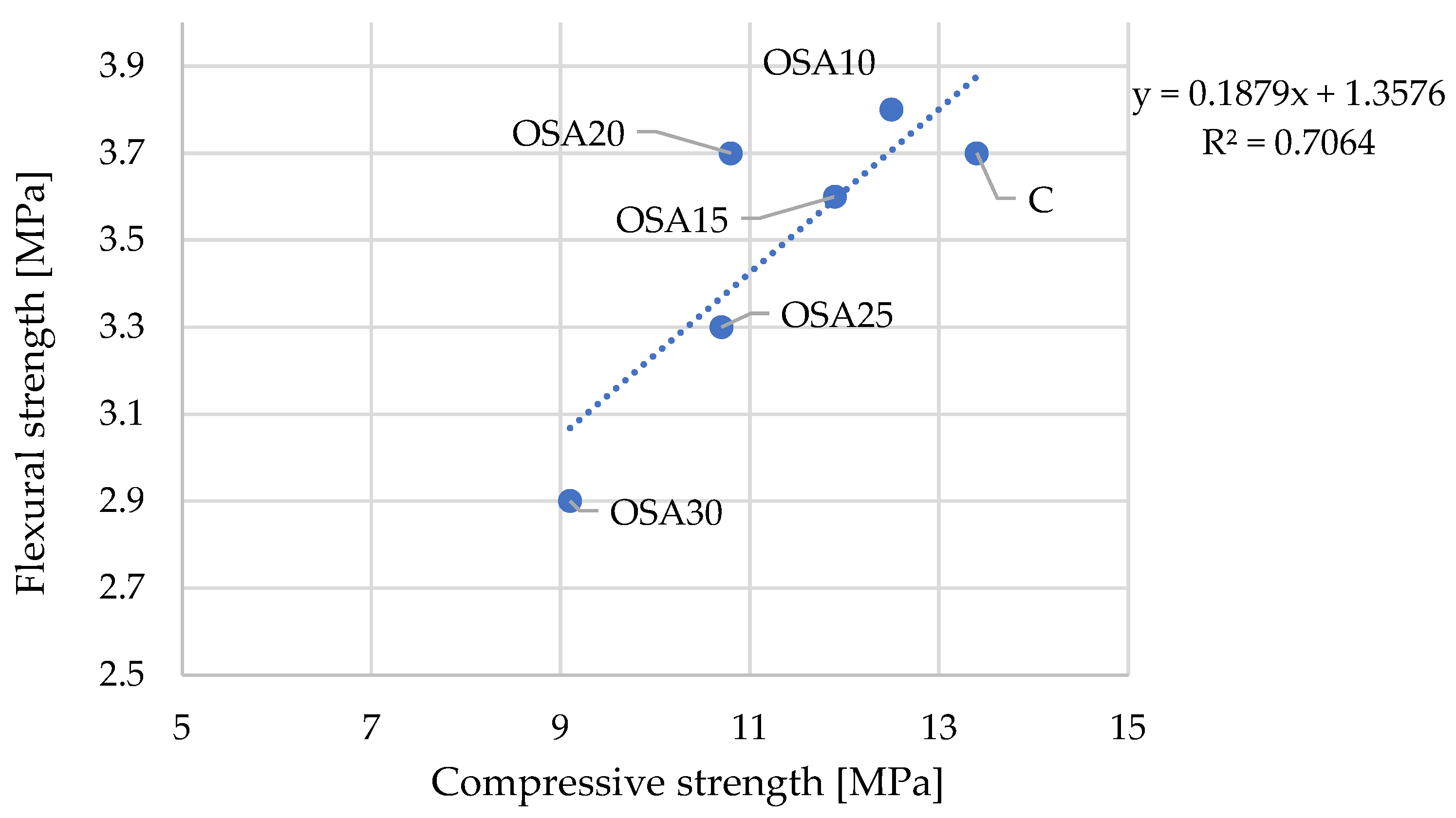
    • Paste ITZs seem adequate for concrete with OSA at a dose of up to 10%. Higher percentages of replacement reduce the compressive strength and provide poor ITZs, with no expectation of additional delayed reactions between hydration products and the OSA.
It may be concluded that replacing cement with OSA by up to 10% provides concrete with acceptable properties, while higher replacement with OSA is relevant for applications where strength is not decisive, such as the encapsulation of low-level radiative waste in steel drums. In such a case, high OSA replacement ratios would be additionally beneficial due to low GWP.
2.
Considering the presence of BFs in the mix:
  • It has been observed that the coating of BFs becomes damaged during the mixing process, and individual basalt microfibres are directly in contact with the concrete matrix.
  • The presence of a thin layer of CSH on the surface of BFs is a result of the alkaline exposure of BFs.
  • Flexural strengths are relatively constant for mixes with up to 20% OSA replacement in the concrete mix.
  • If the compressive strength is the decisive factor for concrete application, 10% OSA replacement in the mix is assessed as sufficient for the utilisation of BFs.

Author Contributions

Conceptualisation, I.N. and E.G.; methodology, I.N. and A.K.; validation, M.V., V.G. and A.K.; formal analysis, K.R.K.; investigation, A.A.J.; resources, A.A.J.; data curation, I.N.; writing—original draft preparation, A.A.J.; writing—review and editing, I.N. and S.K.; visualisation, S.K.; supervision, I.N.; project administration, I.N.; funding acquisition, A.K. All authors have read and agreed to the published version of the manuscript.

Funding

This research was funded by the Baltic Research Programme (Grant No. EEA-RESEARCH-165) “Innovation in concrete design for hazardous waste management applications” under the EEA Grant of Iceland; Liechtenstein and Norway Project (Grant No. EEZ/BPP/VIAA/2021/6).

Data Availability Statement

Data will be made available upon request.

Conflicts of Interest

The authors declare no conflicts of interest. The funders had no role in the design of the study; in the collection, analyses, or interpretation of data; in the writing of the manuscript; or in the decision to publish the results.

References

  1. Jhatial, A.A.; Nováková, I.; Gjerløw, E. A review on emerging cementitious materials, reactivity evaluation and treatment methods. Buildings 2023, 13, 526. [Google Scholar] [CrossRef]
  2. Scrivener, K.L.; Crumbie, A.K.; Laugesen, P. The interfacial transition zone (ITZ) between cement paste and aggregate in concrete. Interface Sci. 2004, 12, 411–421. [Google Scholar] [CrossRef]
  3. Meyyappan, P.L.; Carmichael, M.J. Studies on strength properties of basalt fibre reinforced concrete. Mater. Today Proc. 2021, 43, 2105–2108. [Google Scholar] [CrossRef]
  4. Mujalli, M.A.; Dirar, S.; Mushtaha, E.; Hussien, A.; Maksoud, A. Evaluation of the tensile characteristics and bond behaviour of steel fibre-reinforced concrete: An overview. Fibers 2022, 10, 104. [Google Scholar] [CrossRef]
  5. Deng, Y.; Zhang, Z.; Shi, C.; Wu, Z.; Zhang, C. Steel fiber–matrix interfacial bond in ultra-high performance concrete: A review. Engineering 2023, 22, 215–232. [Google Scholar] [CrossRef]
  6. Jhatial, A.A.; Goh, W.I.; Mastoi, A.K.; Traore, A.F.; Oad, M. Environmental assessment and mechanical properties of Polypropylene fibres reinforced ternary binder foamed concrete. Environ. Sci. Pollut. Res. 2021, 29, 2985–3007. [Google Scholar] [CrossRef]
  7. Al-Kharabsheh, B.N.; Arbili, M.M.; Majdi, A.; Alogla, S.M.; Hakamy, A.; Ahmad, J.; Deifalla, A.F. Basalt fiber reinforced concrete: A compressive review on durability aspects. Materials 2023, 16, 429. [Google Scholar] [CrossRef] [PubMed]
  8. Wang, X.H.; Jacobsen, S.; He, J.Y.; Zhang, Z.L.; Lee, S.F.; Lein, H.L. Application of nanoindentation testing to study of the interfacial transition zone in steel fiber reinforced mortar. Cem. Concr. Res. 2009, 39, 701–715. [Google Scholar] [CrossRef]
  9. Mehdipour, I.; Khayat, K.H. Effect of particle-size distribution and specific surface area of different binder systems on packing density and flow characteristics of cement paste. Cem. Concr. Compos. 2017, 78, 120–131. [Google Scholar] [CrossRef]
  10. Anas, M.; Khan, M.; Bilal, H.; Jadoon, S.; Khan, M.N. Fiber reinforced concrete: A review. Eng. Proc. 2022, 22, 3. [Google Scholar] [CrossRef]
  11. Monaldo, E.; Nerilli, F.; Vairo, G. Basalt-based fiber-reinforced materials and structural applications in civil engineering. Compos. Struct. 2019, 214, 246–263. [Google Scholar] [CrossRef]
  12. Ramesh, B.; Eswari, S. Mechanical behaviour of basalt fibre reinforced concrete: An experimental study. Mater. Today Proc. 2021, 43, 2317–2322. [Google Scholar] [CrossRef]
  13. Katrien, B.; Greet, J.; Saskia, M. Summary Report on the Environmental Potential of Basalt Fibres Versus Glass Fibres; 2017/SMAT/R/1256; Basaltex NV: Wevelgem, Belgium, 2017. [Google Scholar]
  14. Ramakrishnan, V.; Tolmare, N.S.; Brik, V.B. Performance evaluation of 3-D basalt fiber reinforced concrete & basalt rod reinforced concrete. In Final Report for Highway IDEA Project 45; Transportation Research Board: Washington, DC, USA, 1998. [Google Scholar]
  15. Biradar, S.V.; Dileep, M.S.; Vijaya Gowri, D.T. Studies of concrete mechanical properties with basalt fibers. IOP Conf. Ser. Mater. Sci. Eng. 2020, 1006, 012031. [Google Scholar] [CrossRef]
  16. Arslan, M.E. Effects of basalt and glass chopped fibers addition on fracture energy and mechanical properties of ordinary concrete: CMOD measurement. Constr. Build. Mater. 2016, 114, 383–391. [Google Scholar] [CrossRef]
  17. Branston, J.; Das, S.; Kenno, S.Y.; Taylor, C. Mechanical behaviour of basalt fibre reinforced concrete. Constr. Build. Mater. 2016, 124, 878–886. [Google Scholar] [CrossRef]
  18. Szczesniak, M.; Rougelot, T.; Burlion, N.; Shao, J.-F. Compressive strength of cement-based composites: Roles of aggregate diameter and water saturation degree. Cem. Concr. Compos. 2013, 37, 249–258. [Google Scholar] [CrossRef]
  19. Wong, H.S.; Zobel, M.; Buenfeld, N.R.; Zimmerman, R.W. Influence of the interfacial transition zone and microcracking on the diffusivity, permeability and sorptivity of cement-based materials after drying. Mag. Concr. Res. 2009, 61, 571–589. [Google Scholar] [CrossRef]
  20. Hilal, A.A. Microstructure of concrete. In High Performance Concrete Technology and Applications; Yilmaz, S., Ozmen, H.B., Eds.; IntechOpen: Rijeka, Croatia, 2016; Chapter 1. [Google Scholar] [CrossRef]
  21. Hashin, Z.; Monteiro, P.J.M. An inverse method to determine the elastic properties of the interphase between the aggregate and the cement paste. Cem. Concr. Res. 2002, 32, 1291–1300. [Google Scholar] [CrossRef]
  22. Jhatial, A.A.; Goh, W.I.; Mohamad, N.; Rind, T.A.; Sandhu, A.R. Development of thermal insulating lightweight foamed concrete reinforced with polypropylene fibres. Arab. J. Sci. Eng. 2020, 45, 4067–4076. [Google Scholar] [CrossRef]
  23. Voutetaki, M.E.; Naoum, M.C.; Papadopoulos, N.A.; Chalioris, C.E. Cracking diagnosis in fiber-reinforced concrete with synthetic fibers using piezoelectric transducers. Fibers 2022, 10, 5. [Google Scholar] [CrossRef]
  24. Chan, Y.-W.; Chu, S.-H. Effect of silica fume on steel fiber bond characteristics in reactive powder concrete. Cem. Concr. Res. 2004, 34, 1167–1172. [Google Scholar] [CrossRef]
  25. He, S.; Yang, E.-H. Strategic strengthening of the interfacial transition zone (ITZ) between microfiber and cement paste matrix with carbon nanofibers (CNFs). Cem. Concr. Compos. 2021, 119, 104019. [Google Scholar] [CrossRef]
  26. Liu, J.; Farzadnia, N.; Shi, C. Effects of superabsorbent polymer on interfacial transition zone and mechanical properties of ultra-high performance concrete. Constr. Build. Mater. 2020, 231, 117142. [Google Scholar] [CrossRef]
  27. Teixeira, R.S.; Tonoli, G.H.D.; Santos, S.F.; Rayón, E.; Amigó, V.; Savastano, H., Jr.; Rocco Lahr, F.A. Nanoindentation study of the interfacial zone between cellulose fiber and cement matrix in extruded composites. Cem. Concr. Compos. 2018, 85, 1–8. [Google Scholar] [CrossRef]
  28. Bentur, A.; Mindess, S. Fibre Reinforced Cementitious Composites, 2nd ed.; Taylor & Francis Group: London, UK; New York, NY, USA, 2006; ISBN 0-203-08872-7 (ebk). [Google Scholar]
  29. Li, V.C.; Stang, H. Interface property characterization and strengthening mechanisms in fiber reinforced cement based composites. Adv. Cem. Based Mater. 1997, 6, 1–20. [Google Scholar] [CrossRef]
  30. Abdallah, S.; Fan, M.; Rees, D.W.A. Bonding mechanisms and strength of steel fiber–reinforced cementitious composites: Overview. J. Mater. Civ. Eng. 2018, 30, 04018001. [Google Scholar] [CrossRef]
  31. Alanazi, H. Study of the interfacial transition zone characteristics of geopolymer and conventional concretes. Gels 2022, 8, 105. [Google Scholar] [CrossRef] [PubMed]
  32. Adamson, J.; Irha, N.; Adamson, K.; Steinnes, E.; Kirso, U. Effect of oil shale ash application on leaching behavior of arable soils: An experimental study. Oil Shale 2010, 27, 250. [Google Scholar] [CrossRef]
  33. Alaloul, W.S.; Al Salaheen, M.; Malkawi, A.B.; Alzubi, K.; Al-Sabaeei, A.M.; Ali Musarat, M. Utilizing of oil shale ash as a construction material: A systematic review. Constr. Build. Mater. 2021, 299, 123844. [Google Scholar] [CrossRef]
  34. Energia, E. Oil Shale Ash. 2023. Available online: https://www.energia.ee/en/ari/toostuslahendused/tuhk (accessed on 14 July 2023).
  35. Available online: https://www.ragnsells.com/about-us/press-media/articles/oil-shale-ash-in-estonia/ (accessed on 12 June 2024).
  36. Liu, J.; Qiu, J.; Wu, P.; Sun, X.; Zhang, S.; Guo, Z. Calcined oil shale residue as a supplementary cementitious material for ordinary Portland cement. Constr. Build. Mater. 2021, 306, 124849. [Google Scholar] [CrossRef]
  37. Ashteyat, A.M.; Al Rjoub, Y.S.; Obaidat, A.T.; Kirgiz, M.; Abdel-Jaber, M.; Smadi, A. Roller compacted concrete with oil shale ash as a replacement of cement: Mechanical and durability behavior. Int. J. Pavement Res. Technol. 2022, 17, 151–168. [Google Scholar] [CrossRef]
  38. Murad, Y.Z.; Tarawneh, A.; Saleh, E.F.; Musmar, M.; AlMashaqbeh, A.; Alfaouti, Q.T.; Aljaafreh, A.J. Mechanical properties of heat damaged oil shale ash concrete. Innov. Infrastruct. Solut. 2023, 8, 23. [Google Scholar] [CrossRef]
  39. Kalpokaitė-Dičkuvienė, R.; Pitak, I.; Baltušnikas, A.; Čėsnienė, J.; Kriūkienė, R.; Lukošiūtė, S.I. Functional and microstructural alterations in hydrated and freeze-thawed cement-oil shale ash composites. Case Stud. Constr. Mater. 2023, 19, e02302. [Google Scholar] [CrossRef]
  40. ASTM. ASTM C618-22 Standard Specification for Coal Fly Ash and Raw or Calcined Natural Pozzolan for Use in Concrete; ASTM International: West Conshohocken, PA, USA, 2022. [Google Scholar]
  41. Deutsche Basalt Faser. Turbobuild Integral. Available online: https://deutsche-basalt-faser.de/en/products/turbobuild-integral/ (accessed on 14 July 2023).
  42. Medina, C.; Zhu, W.; Howind, T.; Sánchez de Rojas, M.I.; Frías, M. Influence of interfacial transition zone on engineering properties of the concrete manufactured with recycled ceramic aggregate. J. Civil. Eng. Manag. 2014, 21, 83–93. [Google Scholar] [CrossRef]
  43. CEN. EN 450-1 Fly Ash for Concrete—Definition, Specifications and Conformity Criteria; European Committee for Standardization (CEN): Brussels, Belgium, 2012. [Google Scholar]
  44. Suraneni, P.; Burris, L.; Shearer, C.R.; Hooton, R.D. ASTM C618 fly ash specification: Comparison with other specifications, shortcomings, and solutions. ACI Mater. J. 2021, 118, 157–167. [Google Scholar] [CrossRef]
  45. Colombo, A.; Geiker, M.; Justnes, H.; Lauten, R.A.; De Weerdt, K. The effect of calcium lignosulfonate on ettringite formation in cement paste. Cem. Concr. Res. 2018, 107, 188–205. [Google Scholar] [CrossRef]
  46. Lin, C.; Kanstad, T.; Jacobsen, S.; Ji, G. Bonding property between fiber and cementitious matrix: A critical review. Constr. Build. Mater. 2023, 378, 131169. [Google Scholar] [CrossRef]
  47. Khandelwal, S.; Rhee, K.Y. Recent advances in basalt-fiber-reinforced composites: Tailoring the fiber-matrix interface. Compos. B Eng. 2020, 192, 108011. [Google Scholar] [CrossRef]
  48. Mahltig, B. Basalt fibers. In Inorganic and Composite Fibers; Elsevier: Amsterdam, The Netherlands, 2018; pp. 195–217. [Google Scholar] [CrossRef]
  49. Fiore, V.; Scalici, T.; Di Bella, G.; Valenza, A. A review on basalt fibre and its composites. Compos. B Eng. 2015, 74, 74–94. [Google Scholar] [CrossRef]
  50. Wei, C.; Zhou, Q.; Deng, K.; Lin, Y.; Wang, L.; Luo, Y.; Zhang, Y.; Zhou, H. Alkali resistance prediction and degradation mechanism of basalt fiber: Integrated with artificial neural network machine learning model. J. Build. Eng. 2024, 86, 108850. [Google Scholar] [CrossRef]
  51. Available online: www.lca.no (accessed on 16 April 2024).
Figure 1. Microstructure of concrete’s ITZ (CSH = calcium silicate hydrate; CH = calcium hydroxide; and CAS̅H = calcium aluminosulphate hydroxide/ettringite) [20].
Buildings 14 01952 g001
Figure 2. Schematic of the components of the ITZ between the fibre and paste [30].
Buildings 14 01952 g002
Figure 3. SEM images of (a) 24 mm, 2 kg per m3, BF-reinforced concrete and (b) 24 mm, 2 kg per m3, glass fibre-reinforced concrete test specimens [16].
Buildings 14 01952 g003
Figure 4. Samples of (a) OSA [32] and (b) BFs [41] and (c) details of BFs (magnification: 202.7).
Buildings 14 01952 g004
Figure 5. PSDs of binder input materials and individual mixes.
Buildings 14 01952 g005
Figure 6. Flowchart of the experimental work.
Buildings 14 01952 g006
Figure 7. SEM images of the microstructure of the control sample: 100 μm (a) and 500 μm (b).
Buildings 14 01952 g007
Figure 8. SEM image of the sample containing BFs and OSA showing densely formed ITZs.
Buildings 14 01952 g008
Figure 9. SEM images of sample containing BFs and OSA with CSH deposits on fibre surface.
Buildings 14 01952 g009
Figure 10. Compressive and flexural strengths of the concrete mixes.
Buildings 14 01952 g010
Figure 11. GWP of individual mixes.
Buildings 14 01952 g011
Table 1. Chemical compositions of the OSA and PLC (wt.%).
OxidesSiO2Al2O3Fe2O3TiO2CaOMgONa2OK2OMnOSO3P2O5LOI *
OSA33.208.094.440.5337.063.070.263.840.055.450.163.85
PLC19.114.792.850.3361.693.170.081.990.122.020.512.61
* LOI—loss on ignition.
Table 2. Mix designs.
MixPLC
(kg)
OSA
(kg)
DP
(kg)
MS
(kg)
Aggregates (kg)Water
(kg)
SP
(kg)
Fibre
(kg)
0–1.0 mm0.3–2.5 mm4–8 mm
C250.00.0218.213.6572.7954.654.6227.36.368.0
OSA10225.025.0218.213.6572.7954.654.6227.36.368.0
OSA15212.537.5218.213.6572.7954.654.6227.36.368.0
OSA20200.050.0218.213.6572.7954.654.6227.36.368.0
OSA25187.562.5218.213.6572.7954.654.6227.36.368.0
OSA30175.075.0218.213.6572.7954.654.6227.36.368.0
PLC = Portland limestone cement; OSA = Oil shale ash; DP = dolomite powder; MS = microsilica; and SP = superplasticiser.
Table 3. Properties of fresh and hardened concrete mixtures.
Mix Slump (mm)Compressive Strength (MPa)Flexural Strength (MPa)
C22513.43.7
OSA1023012.53.8
OSA1522011.93.6
OSA2018010.83.7
OSA2522010.73.3
OSA302309.12.9
Disclaimer/Publisher’s Note: The statements, opinions and data contained in all publications are solely those of the individual author(s) and contributor(s) and not of MDPI and/or the editor(s). MDPI and/or the editor(s) disclaim responsibility for any injury to people or property resulting from any ideas, methods, instructions or products referred to in the content.

