Article

A Real-Time Study on the Cracking Characteristics of Polyvinyl Alcohol Fiber-Reinforced Geopolymer Composites under Splitting Tensile Load Based on High-Speed Digital Image Correlations

The Key Laboratory of Urban Security and Disaster Engineering of Ministry of Education, Beijing University of Technology, Beijing 100124, China
*
Author to whom correspondence should be addressed.
Buildings 2024, 14(7), 1986; https://doi.org/10.3390/buildings14071986
Submission received: 3 June 2024 / Revised: 20 June 2024 / Accepted: 28 June 2024 / Published: 1 July 2024
(This article belongs to the Section Building Materials, and Repair & Renovation)

Abstract

:
The cracking of geopolymer caused by its brittleness characteristics could reduce the stability and durability of the building structure. Studying the cracking behavior of fiber-reinforced geopolymer composites (FRGCs) is important to evaluate the toughness strengthening of geopolymer. This paper presents a real-time study on the cracking characteristics of FRGCs under splitting tensile load based on high-speed digital image correlation (HDIC) technology. The splitting tensile test was conducted on the FRGC with different fiber content. The real-time variation of strain and displacement field during the splitting process was analyzed. The influence of fiber content on the mechanical properties and crack behavior of FRGCs was discussed. Considering the splitting strength and crack width, the optimal fiber content for FRGCs that satisfied the crack resistance requirement was proposed. The results show that the incorporation of fiber can delay the cracking time and reduce strain change during the splitting process. The splitting tensile strength and the deformation increase as fiber content increases, while the crack width decreases as fiber content increases. The FRGC with 2.0% fiber content can maintain a crack width smaller than 0.1 mm, which satisfies the crack resistance requirements of practical engineering for economic consideration.

1. Introduction

Geopolymer is a new construction material with lower energy consumption, lower pollution, and higher compressive strength, which has been widely used in the construction industry [1,2,3]. However, the brittleness behavior of the geopolymer makes it easy to generate cracks with a large width in the practical application of construction engineering [4]. Cracks reduce the strength and rigidity of the structures, which further influences the safety and stability of the building structure [5]. Cracks also accelerate the invasion of aggressive substances into the geopolymer, such as Cl and SO42−, which reduces the durability of the geopolymer structure. Therefore, it is of great significance to study the crack resistance of geopolymer materials.
The brittleness of geopolymer can be improved by adding fiber to prepare fiber-reinforced geopolymer composites. Many scholars have investigated the strengthening effect of polyvinyl alcohol (PVA) FRGCs under static and dynamic compressive loads [6]. The impact resistance and strength of geopolymer increase as PVA fiber content increases and the addition of fiber can change the failure mode of geopolymer from brittle failure to ductile failure [7]. The effect of PVA fibers on the tensile properties of geopolymer was further investigated and found that the tensile strength and tensile strain of geopolymer increased as PVA fiber content increased [8]. Research was also conducted to study the influence of PVA fiber content on the number and width of cracks after a tensile failure of the geopolymer [9,10]. In previous studies, the deformation and cracking characteristics of geopolymer were mainly measured by displacement gauges or dial indicators [11]. The crack width was mainly calculated by the ratio of the displacement change to the number of cracks after unloading [12]. However, due to the suddenness of geopolymer cracking, the crack initiation and crack propagation behavior of geopolymer are important indexes to evaluate the fiber toughening effect. Therefore, understanding the cracking behavior of fiber-reinforced geopolymer composite is crucial for improving its practical application and needs to be further investigated.
Traditional displacement and strain measurement methods, such as displacement gauges, dial indicators, strain gauges, etc., cannot measure the real-time variation of the full-field displacement and full-field strain of specimens, which makes it difficult to obtain crack propagation characteristics [13,14,15]. Digital image correlation (DIC) technology is an image analysis method to measure the full-field displacement or deformation by analyzing the light intensity probability and statistical data of the particles randomly distributed on the surface of the specimen before and after the deformation [16,17]. Compared with the traditional measurement methods, DIC technology can intuitively, clearly, and accurately describe the variation of the full-field displacement and full-field strain during the deformation of the specimens, which has been widely used in the field of construction engineering [18,19,20,21]. However, the suddenness of cracking in brittle materials makes it difficult for the DIC technology to capture the crack initiation and the crack tip extension. It is urgent to propose a new measurement method. High-speed digital image correlation (HDIC) is a new non-contact measurement technology that combines DIC and high-speed photography [22]. High-speed photography can accurately capture the image of the moment of crack initiation at a higher frame rate. HDIC technology has been used to monitor the crack evolution and failure behavior of brittle materials such as rocks in fracture and impact tests [23,24,25]. What is more, the failure mode of geopolymer changes from brittle failure to ductile failure as fiber content increases, which leads to the change in the cracking behavior of geopolymer [26,27]. Therefore, the cracking behavior of geopolymer composites based on HDIC technology needs further quantitative investigation.
This study experimentally investigated the splitting tensile performance of PVA-FRGC and its cracking behavior. The PVA-FRGC specimens with different fiber contents were prepared and further tested for their mechanical properties under a splitting tensile load. The effect of PVA fiber content on the splitting tensile strength and deformation of geopolymer materials was studied. The displacement field and strain field were analyzed during the splitting process based on HDIC technology. The influence of PVA fiber content on the crack width and strain of FRGC specimens was discussed.

2. Experimental and Methods

2.1. Materials

The main components of PVA-reinforced MK-based geopolymer included metakaolin, alkali activator, and PVA fiber. The kaolin used in this study is from Jiaozuo city in Henan Province, China. After full grinding, high-temperature calcination at 800 °C for 4.0 h, and 1250 mesh sieve sieving, the kaolin was finally made into metakaolin with a particle size of less than 13.0 μm. Its chemical composition is shown in Table 1. The alkali activator was mainly composed of high-modulus (3.24) sodium silicate solution and sodium hydroxide solution. First, the solid mass of sodium hydroxide required to configure the 1.3-modulus sodium silicate solution was calculated using the ratio of Na2O to SiO2. Then, industrial caustic soda with a purity of 99.0% was mixed with water to prepare an 8.0 mol/L sodium hydroxide solution. Finally, the high-modulus sodium silicate solution was slowly poured into the sodium hydroxide aqueous solution to prepare the alkali stimulant. The physical parameters of PVA fiber are shown in Table 2.

2.2. Methods

2.2.1. Preparation of Geopolymer Specimens

In order to study the effect of fiber content on the splitting strength of MK-based geopolymer and the behavior of tensile crack propagation, 5 sets of MK-based geopolymer specimens with different PVA fiber volume proportions (0.0%, 0.5%, 1.0%, 1.5%, and 2.0%) were prepared. Each set had 5 specimens, with a total of 25 specimens. The size of the specimens referred to the standard GB/T50081-2019 [28]. In this study, the geopolymer specimens were prepared using a JJ-5 planetary mixer (Dahong Experimental Instrument Co., Ltd., Cangzhou, China). First, a 1.3-modulus alkali activator solution was prepared by mixing a sodium hydroxide solution and a high-modulus sodium silicate solution [29]. The alkali activator solution was slowly poured into a mixer filled with metakaolin and stirred at a low speed for 5.0 min. Then, the PVA fiber was added to the mixer. The mixer stirred at 164 r/min for 2.0 min to disperse the fibers evenly and then at 360 r/min for 1.0 min to optimize the fluidity of the geopolymer slurry. Finally, the slurry was poured into a triple mold to obtain geopolymer specimens with a size of 100 mm × 100 mm × 100 mm. The specimens were placed into a constant temperature constant humidity curing box (Shenglei Experimental Instrument Co., Ltd., Cangzhou, China) for 1 day with a curing temperature of 20 ± 2 °C and a relative humidity of 95.0%. After 1 day, the specimens were demolded and continued curing for 7 days. Figure 1 shows the MK-based geopolymer specimens prepared in this experiment. It can be seen from the figure that the appearance of the MK-based geopolymer is brick red and does not change significantly with the increase in the PVA fiber content.

2.2.2. Splitting Tensile Test

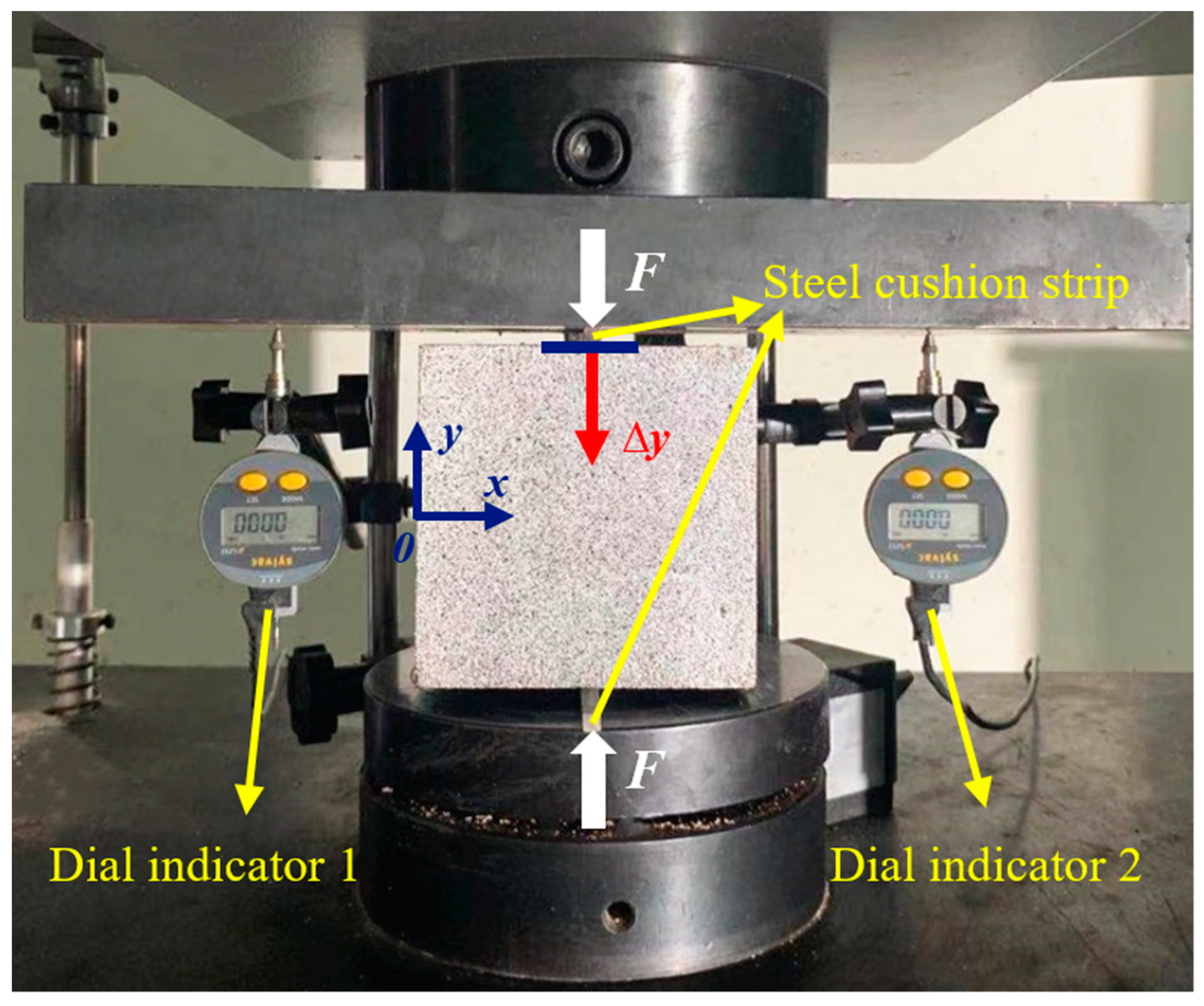
Figure 2 is the splitting tensile test used in this study. As shown in Figure 2, a rectangular mat with a cross-sectional size of 5.0 mm × 5.0 mm was used in the splitting tensile test. The SHT-4605 servo testing machine was used to load the geopolymer specimens at a loading rate of 0.5 kN/s and record the vertical load F. The two dial indicators were set up on both sides of the specimen, and the average of their indicated numbers was used as the compression deformation ∆y of the specimen during the splitting process.

2.2.3. High-Speed Digital Image Correlation (HDIC)

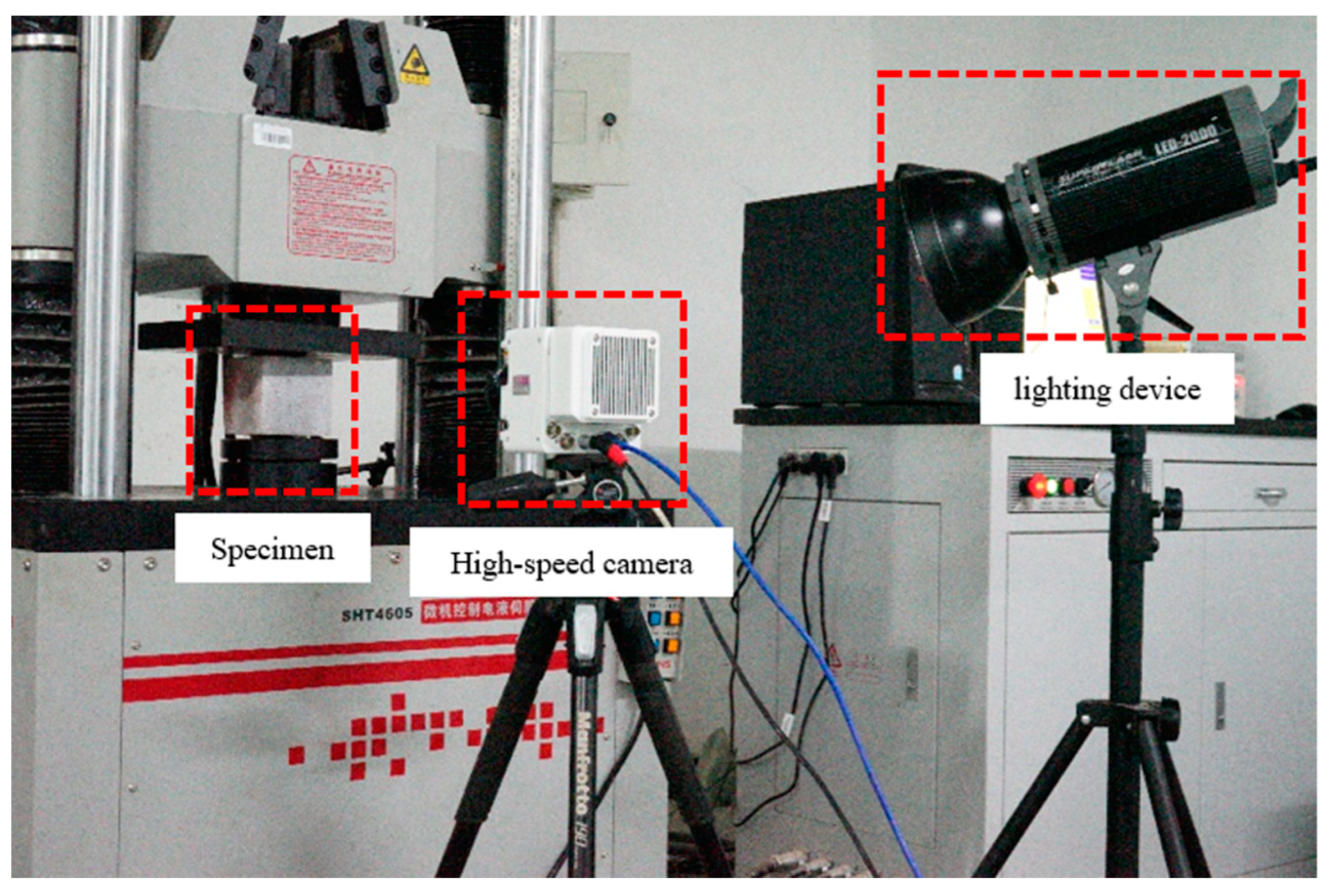
HDIC was applied to analyze the changes in the strain field, the displacement field of the specimen, and the behavior of crack propagation. At first, a sander was used to polish the test surfaces of the specimens. Then, white paint was applied to the study area (ROI) of the specimen. Finally, after the white paint was dried, randomly distributed black paint was sprayed. Figure 3 shows the experimental equipment including high-speed cameras, lighting equipment, and loading devices. As shown in Figure 3, a high-speed camera (Phantom VEO-710L, Wayne, NJ, USA) was used to record the splitting process of the specimens. It was set to take 5000 images per second with a resolution of 1280 × 800 pixels. The image resolution was 0.159 mm per pixel. The analysis area was the same as the surface to be measured, which was 100 mm². The DIC technology was performed with GOM-Correlate-2018 software to obtain the strain distribution images.

3. Results and Discussion

3.1. Splitting Tensile Strength

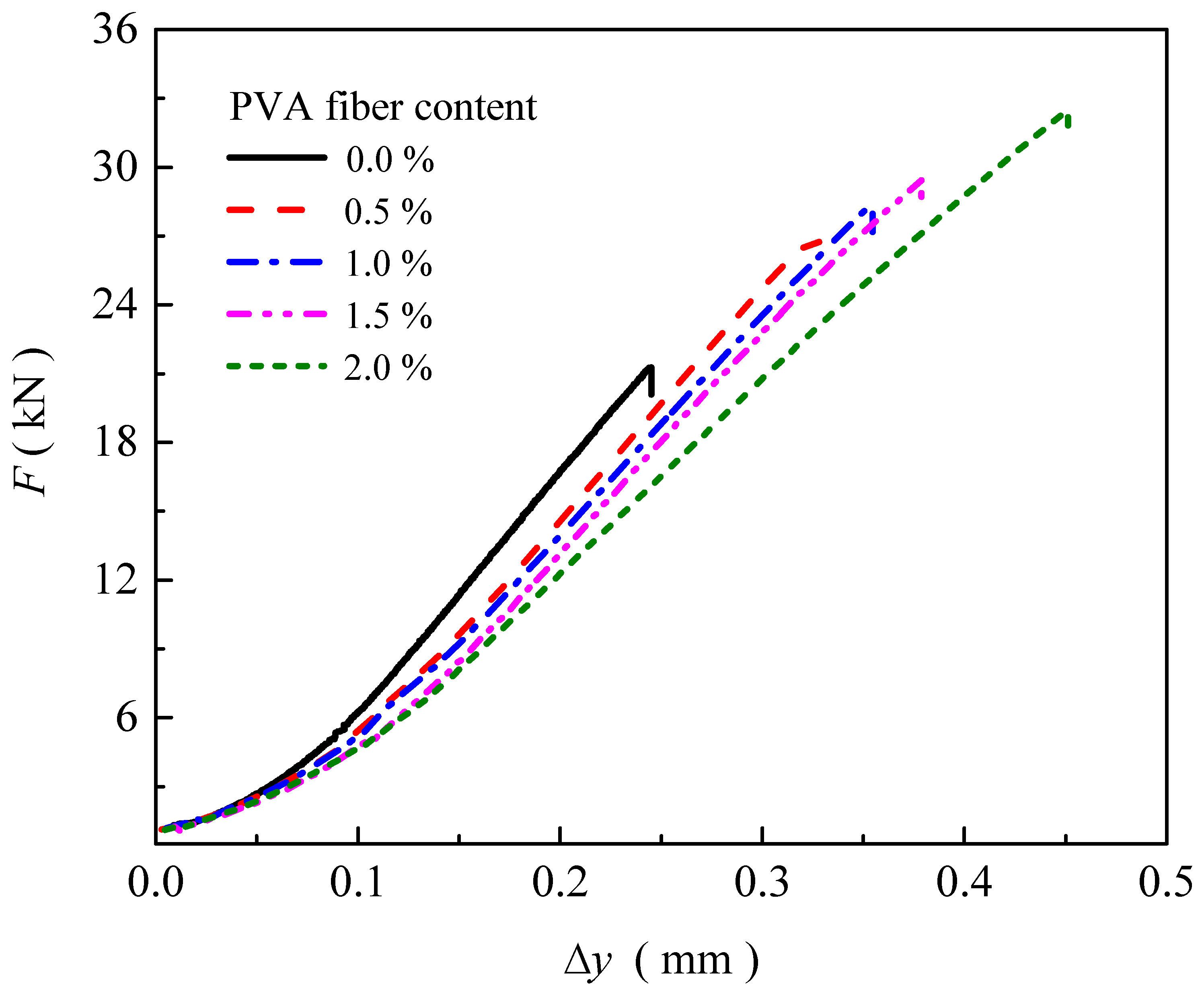
Figure 4 shows the relationship between the load (F) and compression deformation (∆y) of geopolymer specimens with different PVA fiber contents. As shown in Figure 4, the load F increases slowly with ∆y and then increases linearly and sharply. With the increase in PVA fiber content, the slope of the F-∆y curve becomes smaller. When the specimen reaches its ultimate bearing capacity and fails, the specimen no longer continues to be loaded. According to the standard of GBT50081-2019 [28], the splitting tensile strength of the specimens can be calculated by the failure load of the specimen.
Figure 5 shows the relationship between the splitting tensile strength and ultimate compression deformation with the fiber content. It can be seen from Figure 5 that, with the increase in fiber content, the splitting tensile strength and ultimate compressive deformation both show a trend of nonlinear growth, and the characteristic of change is similar. By adding a small amount of PVA fiber, the splitting tensile strength (ultimate compression deformation) increases sharply. When increasing the content of the PVA fiber, the splitting tensile strength (ultimate compression deformation) continues to increase, but the increase is smaller. When the PVA fiber content increases to 2.0%, the splitting tensile strength (ultimate compression deformation) increases significantly. The splitting tensile strength of the MK-based geopolymer without PVA fiber is 1.22 MPa, and the ultimate compression deformation is 0.245 mm. When the fiber content is 0.5%, 1.0%, 1.5%, and 2.0%, the splitting tensile strength increases by 26.9%, 33.1%, 38.8%, and 52.9%, and the ultimate compression deformation increases by 33.9%, 44.5%, 54.6%, and 84.2%, respectively. Research shows that the splitting tensile strength of C30 ordinary concrete without fiber reinforcement is generally about 1.2 MPa, and the ultimate compression deformation is about 0.1 mm [30]. Comparatively, the MK-based geopolymer without fiber exhibits similar performance. Meanwhile, adding fibers to ordinary concrete can moderately increase its splitting tensile strength and deformation resistance. Studies have shown that the inclusion of fibers in concrete typically leads to an improvement in splitting tensile strength by approximately 10% to 40% over plain concrete without fibers [31,32], but the improvements are not as significant as those observed in MK-based geopolymers with 2% PVA fiber content.

3.2. Geopolymer Specimen Failure Modes

Figure 6 shows the geopolymer specimens with different PVA fiber contents after splitting failure. As shown in Figure 6, when the fiber content is 0.0%, a through crack is generated at the centerline of the specimen. Because there is no fiber, the specimen is split into two unconnected parts. A small area of peeling occurs at the upper and lower ends of the crack. When the fiber content is 0.5%, the crack is obvious. The width at the middle of the crack is larger, and the width at both ends of the crack is smaller. Due to the effect of the fiber, the left and right parts of the specimen are still in a connected state. When the fiber content is larger than 1.0%, the width of the crack is small, and it is difficult to observe the crack propagation behavior.

3.3. The Variation of Full-Field Displacement and Strain

HDIC was used to analyze the evolution process of the displacement field and the strain field in the process of specimen splitting failure. The split moment was defined as t = 0.0 ms, and three time nodes (t = 0.2 ms, t = 2.2 ms, and t = 9.2 ms) were selected for the strain field and displacement field analysis to capture the initial crack process, crack progression process, and the final failure process, respectively.
Figure 7 shows the real-time variation of the strain field during the splitting failure of specimens. As shown in Figure 7, the middle strain is large, and the strain at both ends is small. With the same PVA fiber content, the strain gradually increases as loading time increases. At the same time, the strain gradually decreases with the increase in the PVA fiber content. The specimen initially cracks in the center. Then, the crack gradually expands to the upper and lower ends until a through crack is formed.
Figure 8 shows the real-time variation of the displacement field during the splitting failure of specimens. As shown in Figure 8, the position of the vertical centerline of the specimen has displacement field changes. Due to the splitting failure, the specimen cracks from the center line position and separates to the left and right sides. The displacement of the center position changes greatly, and the displacement of the upper and lower ends is smaller. The change characteristics of the displacement field on the upper and lower sides of the specimen are the same, which indicates that the specimen is not distorted during the splitting process. With the same PVA fiber content, the displacement gradually increases as loading time increases. At the same time, the displacement gradually decreases with the increase in the PVA fiber content.

3.4. Analysis of Cracking Propagation Behavior

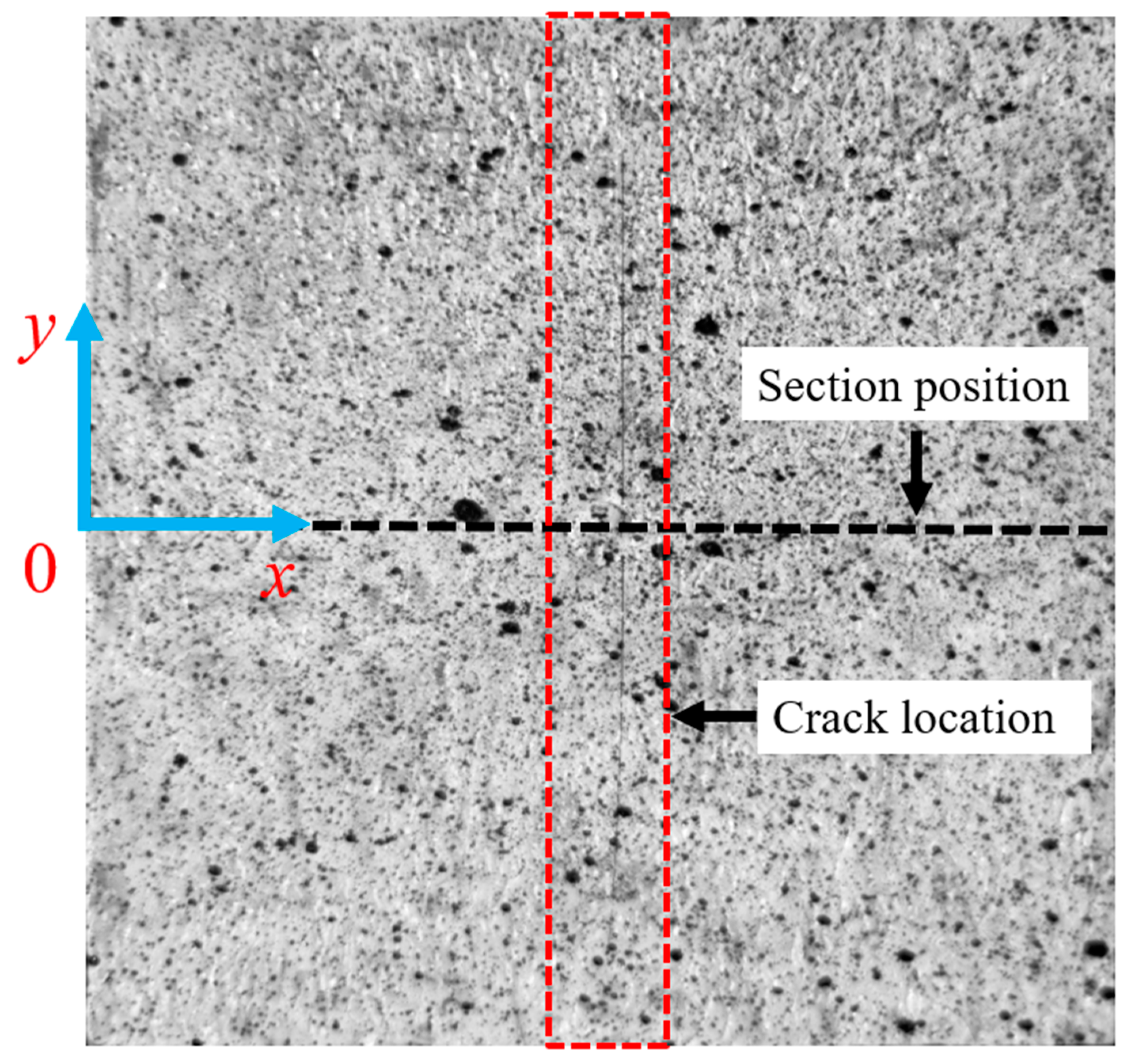
It can be seen from the strain and displacement contours that the width of the crack is not uniform. The crack width in the middle position is larger, and the crack width at the upper and lower ends is smaller. Figure 9 is the schematic diagram of the DIC analysis method. In order to analyze the influence of PVA fiber content on the maximum width of the crack, the x-y coordinate system was set in the analysis area and the y = 0 cross-sectional was taken as the analysis object [33,34]. The change characteristics of the strain and displacement of the y = 0 cross-sectional with time were obtained.
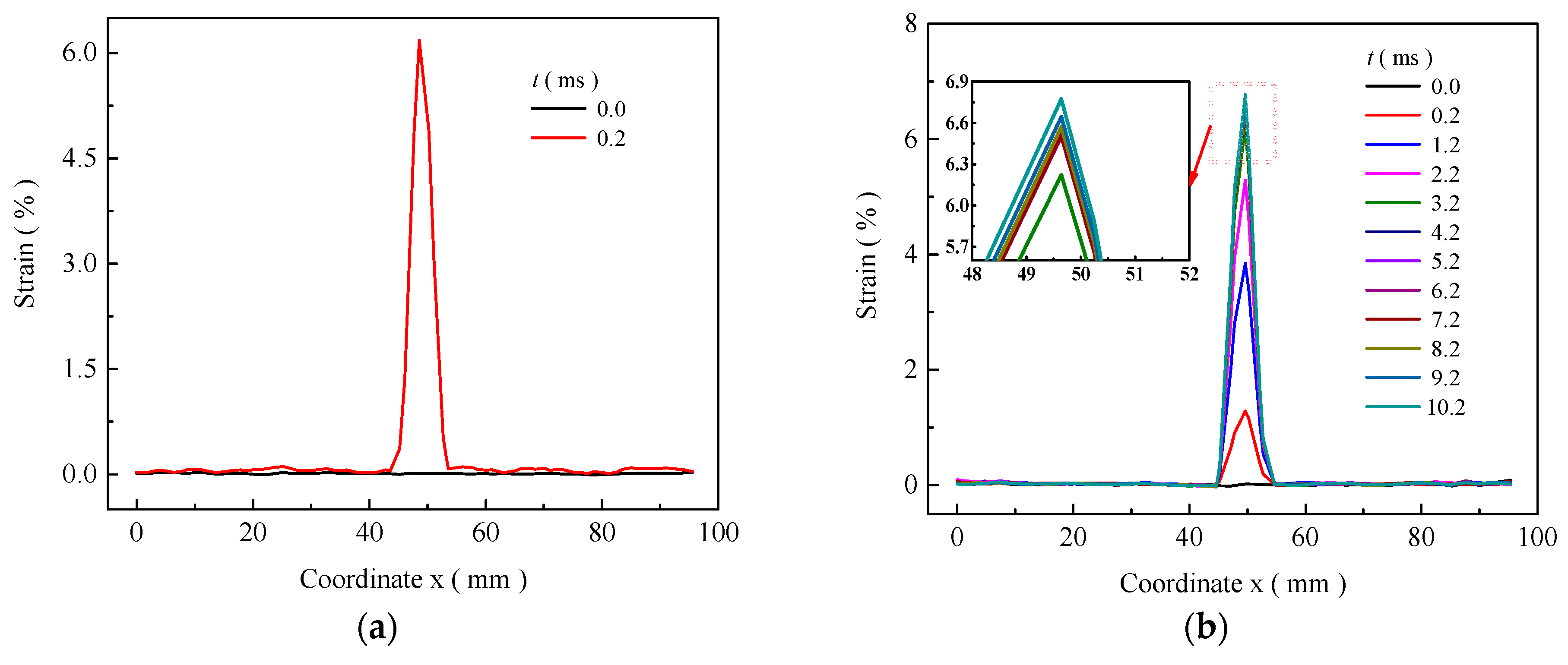
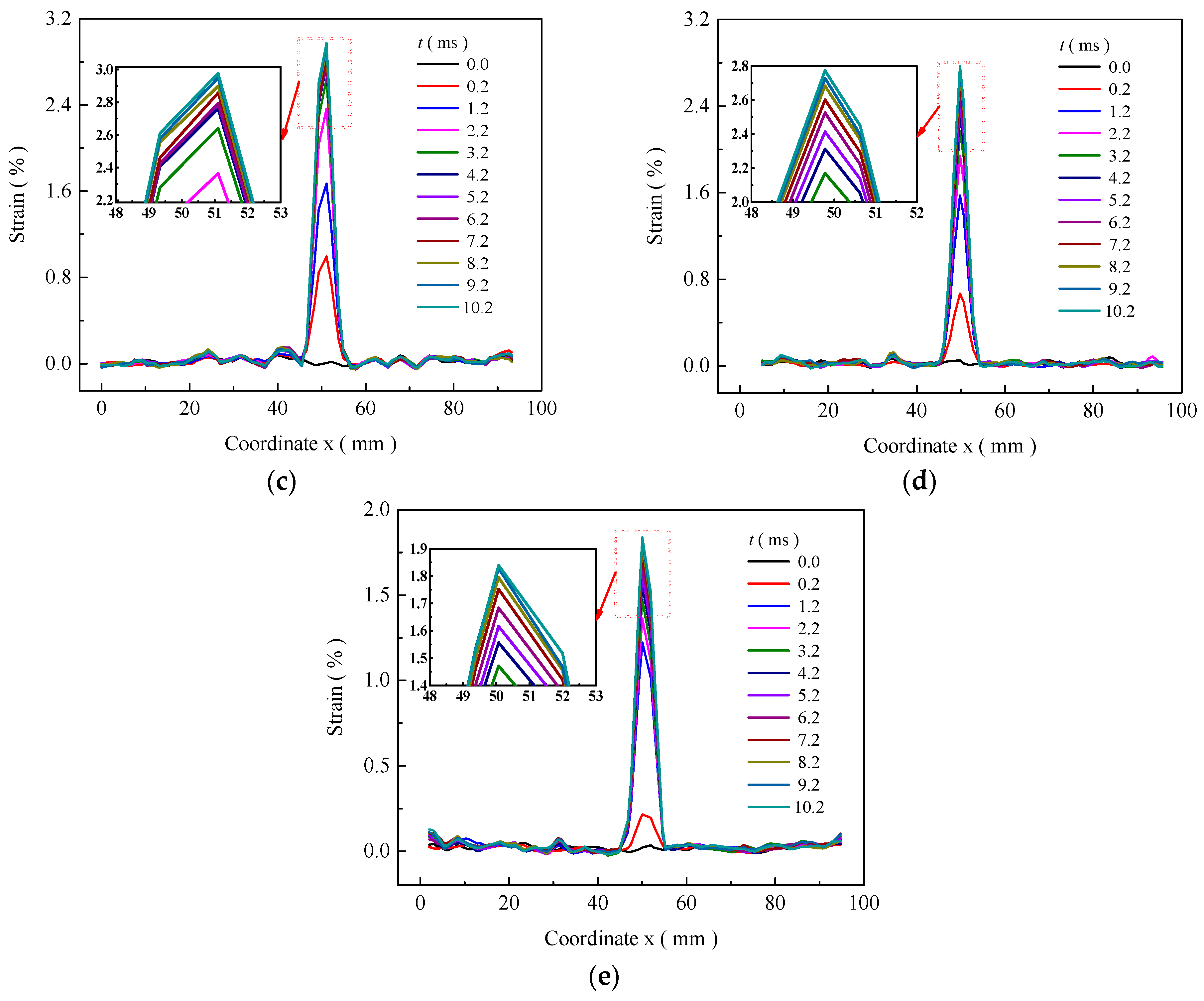
Figure 10 shows the relationship between the y = 0 cross-sectional strain and time with different PVA fiber contents. It can be seen from Figure 10 that the change characteristics of the curves are similar. At t = 0 ms, the strain is stable and close to 0.0%. After t = 0.2 ms, the strain curve remains stable before x = 45.0 mm and after x = 65.0 mm, and a sudden change occurs between x = 45.0 mm and x = 65.0 mm. The strain first increases sharply, then decreases sharply, and finally returns to x = 65.0 mm. All the specimens show the characteristics of a single vertical crack after splitting failure. The vertical coordinate of the crack is between x = 45.0 mm and x = 65.0 mm. When the fiber content is 0.0%, the specimen has a strain of more than 6.0% in 0.2 ms after the splitting failure. When the fiber content is larger than 0.5%, the peak strain has the same changing characteristics with time, initially increasing sharply and then becoming stable.
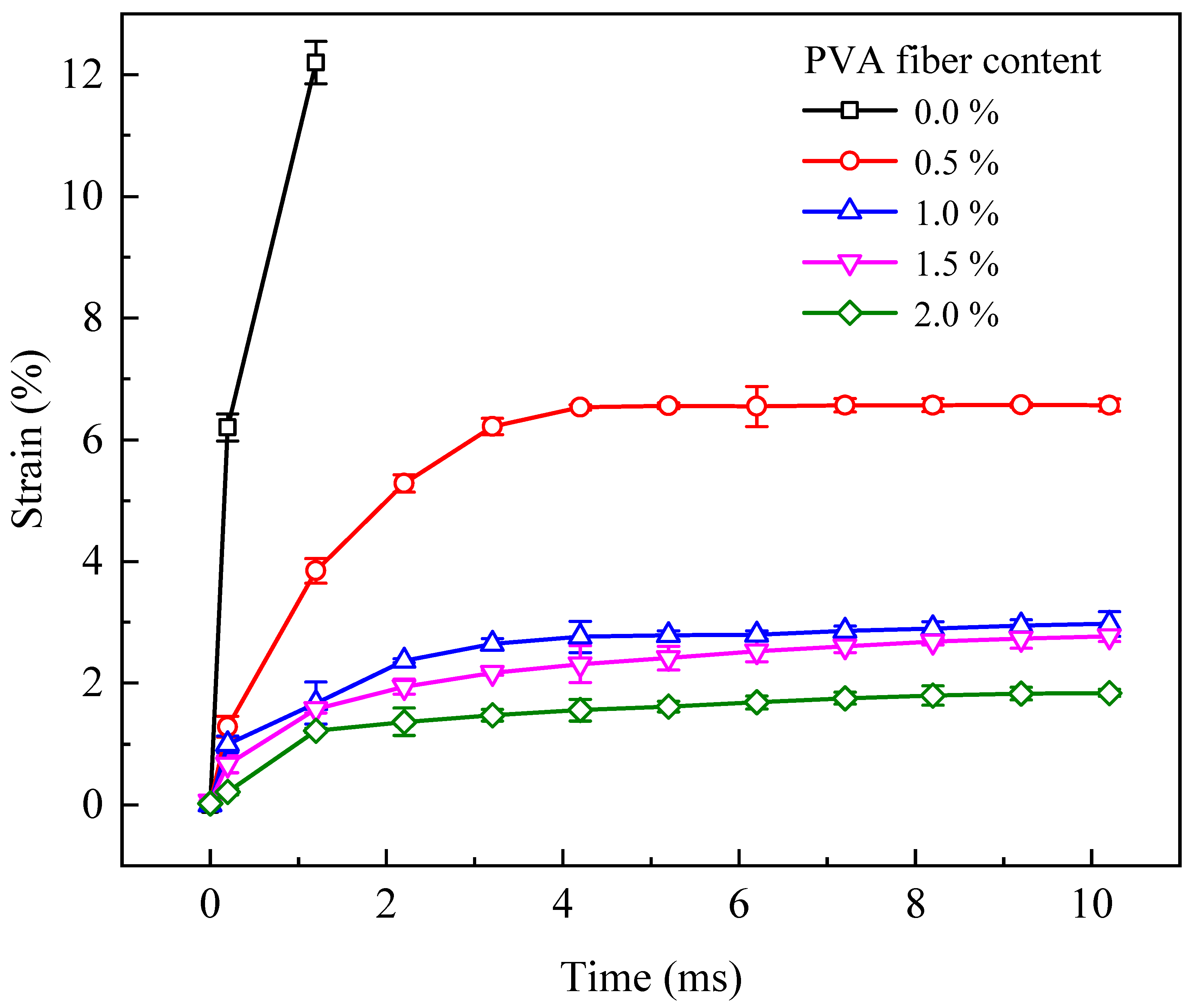
The peak strain under different PVA fiber contents is analyzed. Figure 11 shows the change in the peak strain of the y = 0 section with time under different PVA fiber contents. As shown in Figure 11, when the fiber content is 0.0%, the strain larger than 6.0% occurs at the moment of splitting failure of the specimen and then increases linearly with time. When the fiber content is larger than 0.5%, the peak strain gradually increases with time and then tends to be stable. The rate of strain changes gradually decreases with time, and the stable peak strain gradually decreases with the increase in fiber parameters. The strain of the specimen with 0.5% PVA fiber content after splitting failure is 6.57%. When the PVA fiber content of the specimen is increased to 1.0%, 1.5% and 2.0%, the maximum peak strain decreases by 54.8%, 57.8%, and 72.0%, respectively.
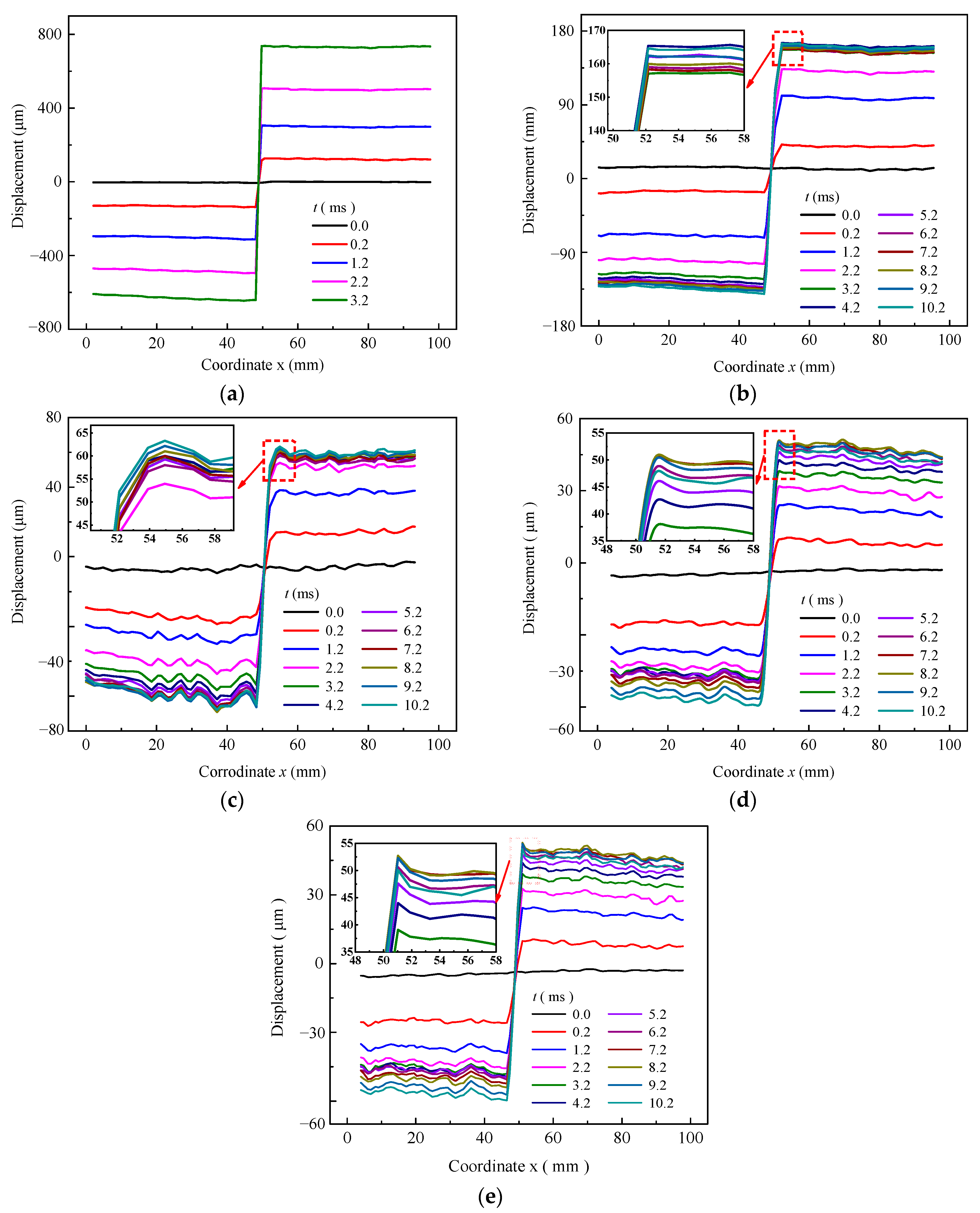
Figure 12 shows the relationship between the y = 0 cross-sectional displacement and time under different fiber contents. The difference between the positive and negative displacement before and after the sudden change in displacement at the x = 50 coordinate is defined as the width of the cross-sectional crack. As shown in Figure 12, the change characteristics of the y = 0 section displacement curve with time under different PVA fiber contents are similar. At t = 0 ms, the displacement on the section is stable and close to 0.0 μm. After t = 0.2 ms, the displacements within the x = 0.0 and x = 50.0 coordinates first gradually decrease with time and then become stable. The displacements within the x = 50.0 and x = 100.0 coordinates first gradually increase with time and then become stable. It shows that a crack with a certain width is formed in the specimen after t = 0.2 ms. When the PVA fiber content is 0.0%, the crack width increases indefinitely with time. After adding PVA fiber, the crack width gradually increased with time and then stabilized.
Figure 13 shows the relationship between the crack width of the y = 0 cross-section and time. As shown in Figure 13, the crack width under different PVA fiber content has a similar changing tendency over time, at first gradually increasing, and then tending to be stable, except that the PVA fiber content is 0.0%. When the PVA fiber content is 0.0%, the crack with a width of 0.26 mm was generated at the instant of splitting failure of the specimen, and the width of the crack increased linearly with time. With the increase in PVA fiber content, the maximum crack width and crack propagation speed gradually decrease. When the PVA fiber content is 0.5%, the maximum crack width is 0.3 mm. When the PVA fiber content increases to 1.0%, 1.5%, and 2.0%, the crack width decreases by 53.0%, 66.4%, and 70.9%, respectively. According to the standard of GB50010-2010 [35], the maximum allowable crack width for concrete is 0.3 mm. This shows that the crack width of geopolymer concrete with 1.0%, 1.5%, and 2.0% PVA fiber content all meet the specification requirements. When the PVA fiber content is 2.0%, the crack width is only 0.087 mm, less than 0.1 mm.

4. Conclusions

The influence of PVA fiber content on the splitting tensile properties of MK-based geopolymer was studied. Based on the HDIC, the strain field and the displacement field in the splitting tensile test were analyzed. The influence of fiber content on the splitting tensile strength and the crack width of the geopolymer was discussed. The following conclusions are drawn:
(1)
The PVA fiber can enhance the splitting mechanical properties of geopolymer. The splitting tensile strength and ultimate deformation increase as PVA fiber content increases, while the strain and displacement decrease as PVA fiber content increases. The splitting tensile strength of the geopolymer without PVA fiber is 1.22 MPa, and the ultimate compression deformation is 0.245 mm. When the fiber content was increased to 2.0%, the split tensile strength increased by 52.9%, and the ultimate compression deflection increased by 84.2%.
(2)
The incorporation of fiber can delay the cracking time and reduce strain change during the splitting process. When the fiber content is larger than 0.5%, the peak strain gradually increases with time and then tends to be stable. The maximum peak strain of the geopolymer decreases by 72.0% as the fiber content increases from 0.0% to 2.0%.
(3)
With the increase in PVA fiber content, the crack width gradually decreases, and the crack propagation speed gradually slows down. The maximum crack width was 0.3 mm at 0.5% PVA fiber content, while it decreased by 53.0%, 66.4%, and 70.9% as the PVA fiber content increased to 1.0%, 1.5%, and 2.0%, respectively.
(4)
Geopolymers with 1.0%, 1.5%, and 2.0% PVA fiber all meet the standard of GB50010-2010 for concrete structures, which requires crack widths to be less than 0.3 mm. The geopolymer with 2.0% fiber content shows the best anti-cracking performance, and the crack width is only 0.087 mm, less than 0.1 mm, which meets the crack resistance requirements of the actual project for economic consideration.

Author Contributions

Methodology, Y.Z.; Investigation, W.Z. and L.F.; Writing—original draft, Y.S. and W.Z.; Writing—review & editing, Y.Z. and W.Z. All authors have read and agreed to the published version of the manuscript.

Funding

This research was funded by the project (23073005) and the project (22035011).

Data Availability Statement

Data are contained within the article.

Conflicts of Interest

The authors declare no conflict of interest.

References

  1. Davidovits, J. Geopolymers: Inorganic Polymeric New Materials. J. Therm. Anal. Calorim. 1991, 37, 1633–1656. [Google Scholar] [CrossRef]
  2. Roy, D.M. New strong cement materials: Chemically bonded ceramics. Science 1987, 235, 651–658. [Google Scholar] [CrossRef] [PubMed]
  3. Duxson, P.; Mallicoat, S.W.; Lukey, G.C.; Kriven, W.M.; van Deventer, J.S.J. The effect of alkali and Si/Al ratio on the development of mechanical properties of metakaolin-based geopolymers. Colloid Surf. A-Physicochem. Eng. Asp. 2007, 292, 8–20. [Google Scholar] [CrossRef]
  4. Ferone, C.; Roviello, G.; Colangelo, F.; Cioffi, R.; Tarallo, O. Novel hybrid organic-geopolymer materials. Appl. Clay Sci. 2013, 73, 42–50. [Google Scholar] [CrossRef]
  5. Pan, Z.; Sanjayan, J.G.; Rangan, B.V. Fracture properties of geopolymer paste and concrete. Mag. Conc. Res. 2011, 63, 763–771. [Google Scholar] [CrossRef]
  6. Zhang, Y.S.; Sun, W.; Li, Z.J.; Zhou, X.M.; Eddie; Chau, C.K. Impact properties of geopolymer based extrudates incorporated with fly ash and PVA short fiber. Constr. Build. Mater. 2006, 22, 370–383. [Google Scholar]
  7. Zhang, Y.S.; Sun, W.; Li, Z.J. Impact behavior and microstructural characteristics of PVA fiber reinforced fly ash-geopolymer boards prepared by extrusion technique. J. Mater. Sci. 2006, 41, 2787–2794. [Google Scholar]
  8. Nematollahi, B.; Sanjayan, J.; Shaikh, F.U.A. Tensile strain hardening behavior of PVA Fiber-reinforced engineered geopolymer composite. J. Mater. Civil Eng. 2015, 27, 04015001. [Google Scholar] [CrossRef]
  9. Guo, X.L.; Yang, J.Y. Intrinsic properties and micro-crack characteristics of ultra-high toughness fly ash/steel slag based geopolymer. Constr. Build. Mater. 2020, 230, 116965. [Google Scholar] [CrossRef]
  10. Kan, L.L.; Zhang, L.; Zhao, Y.J.; Wu, M. Properties of polyvinyl alcohol fiber reinforced fly ash based Engineered Geopolymer Composites with zeolite replacement. Constr. Build. Mater. 2019, 231, 117161. [Google Scholar] [CrossRef]
  11. Kan, L.L.; Lv, J.W.; Duan, B.B.; Wu, M. Self-healing of Engineered Geopolymer Composites prepared by fly ash and metakaolin. Cem. Concr. Res. 2019, 125, 105895. [Google Scholar] [CrossRef]
  12. Nematollahi, B.; Sanjayan, J.; Shaikh, F.U.A. Matrix design of strain hardening fiber reinforced engineered geopolymer composite. Compos. Part B Eng. 2016, 89, 253–265. [Google Scholar] [CrossRef]
  13. Odimegwu, T.C.; Kaish, A.B.M.A.; Jamil, M.; Zain, M.F.M.; Turlanbekov, A.; Al Zand, A.W. Mechanical characterization of geopolymer paste and mortar fabricated from alum sludge and fly ash. Buildings 2023, 13, 2118. [Google Scholar] [CrossRef]
  14. Zuaiter, M.; El-Hassan, H.; El-Maaddawy, T.; El-Ariss, B. Properties of slag-fly ash blended geopolymer concrete reinforced with hybrid glass fibers. Buildings 2022, 12, 1114. [Google Scholar] [CrossRef]
  15. Ramesh, V.A.; Jarghouyeh, E.N.; Alraeeini, A.S.; Al-Fakih, A.; Li, C.G. Optimisation investigation and bond-slip behaviour of high strength PVA-engineered geopolymer composites (EGC) cured in ambient temperatures. Buildings 2023, 13, 3020. [Google Scholar] [CrossRef]
  16. Michaud, K.; Hoult, N.; Lotfy, A.; Lum, P. Performance in shear of reinforced concrete slabs containing recycled concrete aggregate. Mater. Struct. 2016, 49, 4425–4438. [Google Scholar] [CrossRef]
  17. El Ghadioui, R.; Proske, T.; Tran, N.L.; Graubner, C.A. Structural behaviour of CFRP reinforced concrete members under bending and shear loads. Mater. Struct. 2020, 53, 63. [Google Scholar] [CrossRef]
  18. Wu, B.; Jin, H.M. Compressive fatigue behavior of compound concrete containing demolished concrete lumps. Constr. Build. Mater. 2019, 210, 140–156. [Google Scholar] [CrossRef]
  19. Lai, D.D.; Demartino, C.; Db, Y.X. High-strain rate tension behavior of fiber-reinforced rubberized concrete. Cem. Concr. Compos. 2022, 131, 104554. [Google Scholar] [CrossRef]
  20. Roziere, E.; Cortas, R.; Loukili, A. Tensile behaviour of early age concrete: New methods of investigation. Cem. Concr. Compos. 2015, 55, 153–161. [Google Scholar] [CrossRef]
  21. Lee, I.W.; Park, J.; Kim, D.J.; Pyo, S. Effects of abraded fine particle content on strength of quick-hardening concrete. Cem. Concr. Compos. 2019, 96, 225–237. [Google Scholar] [CrossRef]
  22. Zhang, D.B.; Zhao, J. Determination of mechanical properties and full-field strain measurements of rock material under dynamic loads. Int. J. Rock Mech. Min. Sci. 2013, 60, 423–439. [Google Scholar] [CrossRef]
  23. Fan, L.F.; Yang, Q.H.; Du, X.L. Spalling characteristics of high-temperature treated granitic rock at different strain rates. J. Rock Mech. Geotech. Eng. 2024, 16, 1280–1288. [Google Scholar] [CrossRef]
  24. Yang, Q.H.; Fan, L.F.; Du, X.L. Determination of wave propagation coefficients of the granite by high-speed digital image correlation (HDIC). Rock Mech. Rock Eng. 2022, 55, 4497–4505. [Google Scholar] [CrossRef]
  25. Flores, M.; Mollenhauer, D.; Runatunga, V.; Beberniss, T.; Rapking, D.; Pankow, M. High-speed 3D digital image correlation of low-velocity impacts on composite plates. Compos. Part B-Eng. 2017, 131, 153–164. [Google Scholar] [CrossRef]
  26. Ranjbar, N.; Zhang, M.Z. Fiber-reinforced geopolymer composites: A review. Cem. Concr. Compos. 2020, 107, 103498. [Google Scholar] [CrossRef]
  27. Abbas, A.G.N.; Aziz, F.N.A.A.; Abdan, K.; Nasir, N.A.M.; Huseien, G.F. A state-of-the art review on fibre-reinforced geopolymer composites. Constr. Build. Mater. 2022, 330, 127187. [Google Scholar] [CrossRef]
  28. GB/T50081-2019; Standard for Test Methods of Concrete Physical and Mechanical Properties. Ministry of Housing and Urban Rural Development of the People’s Republic of China: Beijing, China, 2019.
  29. Palomoa, A.; Grutzeck, M.W.; Blancoa, M.T. Alkali-activated fly ashes: A cement for the future. Cem. Concr. Res. 1999, 29, 1323–1329. [Google Scholar] [CrossRef]
  30. Jiang, W.; Xie, Y.; Li, W.; Wu, J.; Long, G. Prediction of the Splitting Tensile Strength of the Bonding Interface by Combining the Support Vector Machine with the Particle Swarm Optimization Algorithm. Eng. Struct. 2021, 230, 111696. [Google Scholar] [CrossRef]
  31. Zhang, P.; Wang, J.; Li, Q.; Wan, J.; Ling, Y. Mechanical and Fracture Properties of Steel Fiber-Reinforced Geopolymer Concrete. Sci. Eng. Compos. Mater. 2021, 28, 299–313. [Google Scholar] [CrossRef]
  32. Mahmood, A.; Noman, M.T.; Pechočiaková, M.; Amor, N.; Petrů, M.; Abdelkader, M.; Militký, J.; Sozcu, S.; Hassan, S.Z.U. Geopolymers and Fiber-Reinforced Concrete Composites in Civil Engineering. Polymers 2021, 13, 2099. [Google Scholar] [CrossRef] [PubMed]
  33. Zhong, W.L.; Zhang, Y.H.; Fan, L.F. High-ductile engineered geopolymer composites (EGC) prepared by calcined natural clay. J. Build. Eng. 2023, 63, 105456. [Google Scholar] [CrossRef]
  34. Zhong, W.L.; Sun, Y.H.; Zhao, X.; Fan, L.F. Study on synthesis and water stability of geopolymer pavement base material using waste sludge. J. Clean. Prod. 2024, 445, 141331. [Google Scholar] [CrossRef]
  35. GB 50010-2010; Code for Design of Concrete Structures. Ministry of Housing and Urban Rural Development of the People’s Republic of China: Beijing, China, 2010.
Figure 1. Geopolymer specimens with different fiber contents and specimen dimensions.
Buildings 14 01986 g001
Figure 2. Splitting tensile test used in this study.
Buildings 14 01986 g002
Figure 3. High-speed digital image correlation (HDIC) technology.
Buildings 14 01986 g003
Figure 4. The relationship between the load and compression deformation of FRGCs under different PVA fiber contents.
Buildings 14 01986 g004
Figure 5. The effect of PVA fiber content on splitting tensile strength and ultimate compression deformation of FRGCs.
Buildings 14 01986 g005
Figure 6. The failure modes of FRGCs with different fiber content after the splitting tensile test.
Buildings 14 01986 g006
Figure 7. The variation of the full-field strain of FRGCs with different fiber content with time.
Buildings 14 01986 g007
Figure 8. The variation of the full-field displacement of FRGCs with different fiber content with time.
Buildings 14 01986 g008
Figure 9. Schematic diagram of DIC analysis method proposed in this study.
Buildings 14 01986 g009
Figure 10. The relationship between the cross-sectional strain of y = 0 and the coordinate in the x direction at different moments. (a) 0.0%; (b) 0.5%; (c) 1.0%; (d) 1.5%; (e) 2.0%.
Buildings 14 01986 g010aBuildings 14 01986 g010b
Figure 11. The relationship between the peak strain of the y = 0 cross-section and time under different PVA fiber contents.
Buildings 14 01986 g011
Figure 12. The relationship between the cross-sectional displacement of y = 0 and the coordinate in the x direction at different moments. (a) 0.0%; (b) 0.5%; (c) 1.0%; (d) 1.5%; (e) 2.0%.
Buildings 14 01986 g012
Figure 13. The relationship between the crack width of the y = 0 section and time under different PVA fiber contents.
Buildings 14 01986 g013
Table 1. Chemical composition of metakaolin used in this study.
CompositionAl2O3SiO2Na2O/K2OOthers
Content43.20%49.10%0.57%7.13%
Table 2. Physical parameters of PVA fiber.
Density
(g/cm3)
Tensile Strength
(MPa)
Elastic Modulus
(GPa)
Diameter
(mm)
Length
(mm)
1.3162042.80.03912
Disclaimer/Publisher’s Note: The statements, opinions and data contained in all publications are solely those of the individual author(s) and contributor(s) and not of MDPI and/or the editor(s). MDPI and/or the editor(s) disclaim responsibility for any injury to people or property resulting from any ideas, methods, instructions or products referred to in the content.