
Simplified Formula for Nominal Force at Critical Welds in the Lower Chord Node of a Novel Bracket-Crane Truss Structure
 ,
,
Abstract
:1. Introduction
2. Aim of this Study
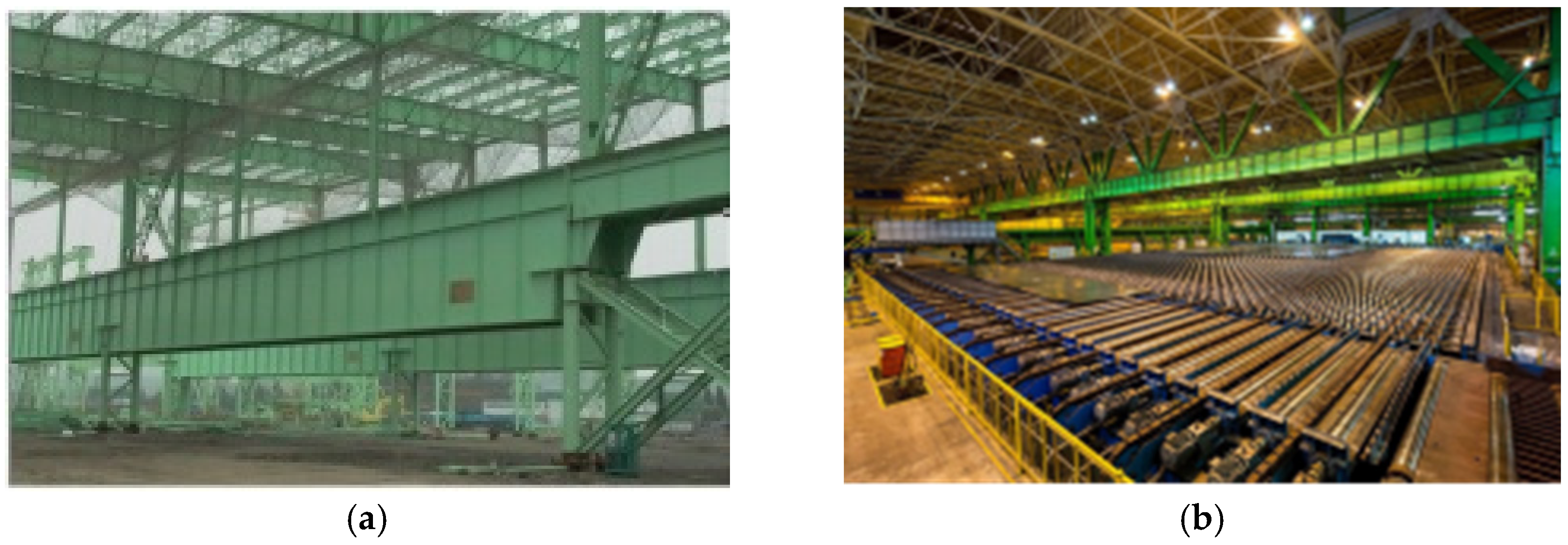
3. Engineering Background
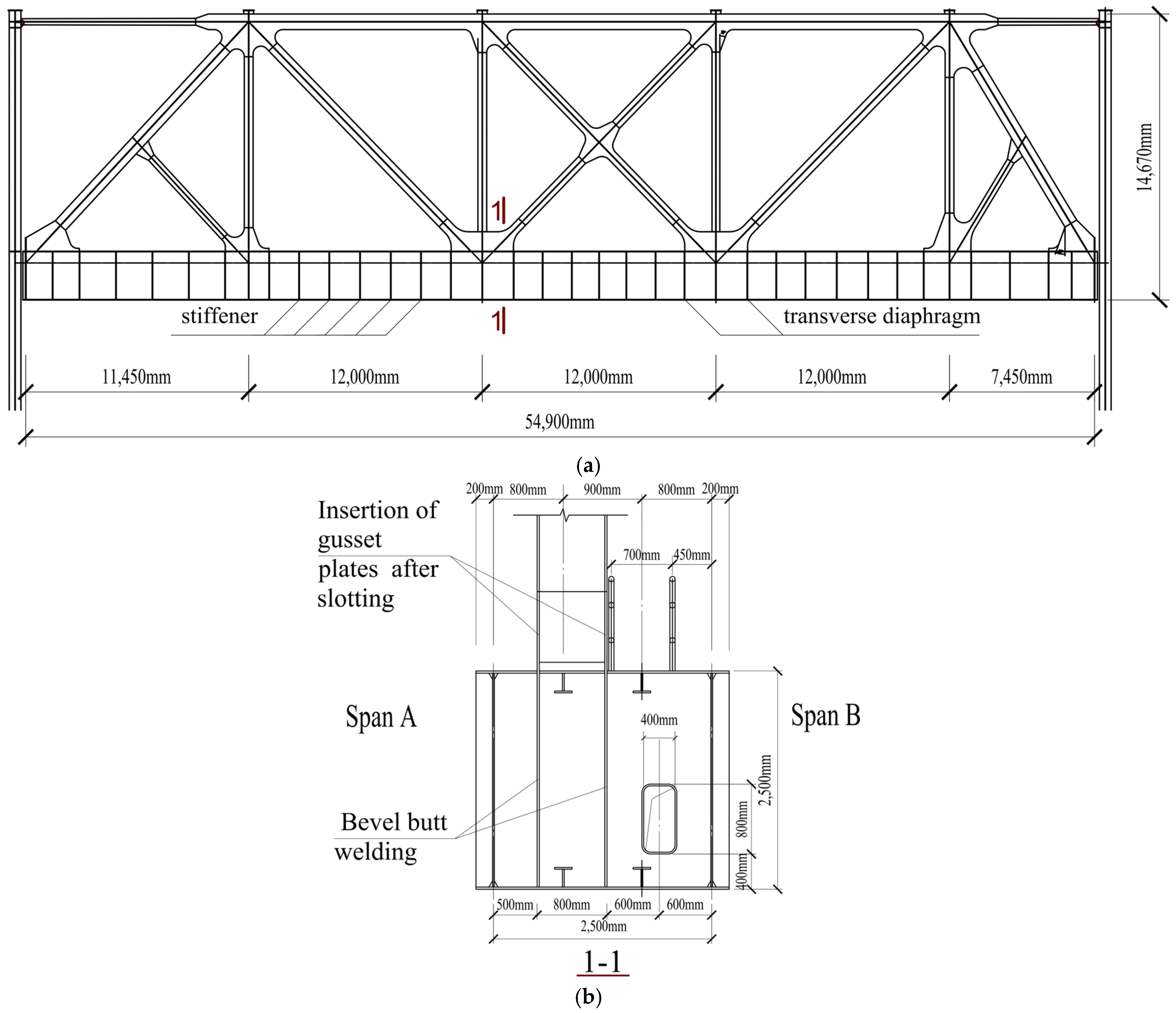
3.1. Structural Arrangement
3.2. Sectional Information
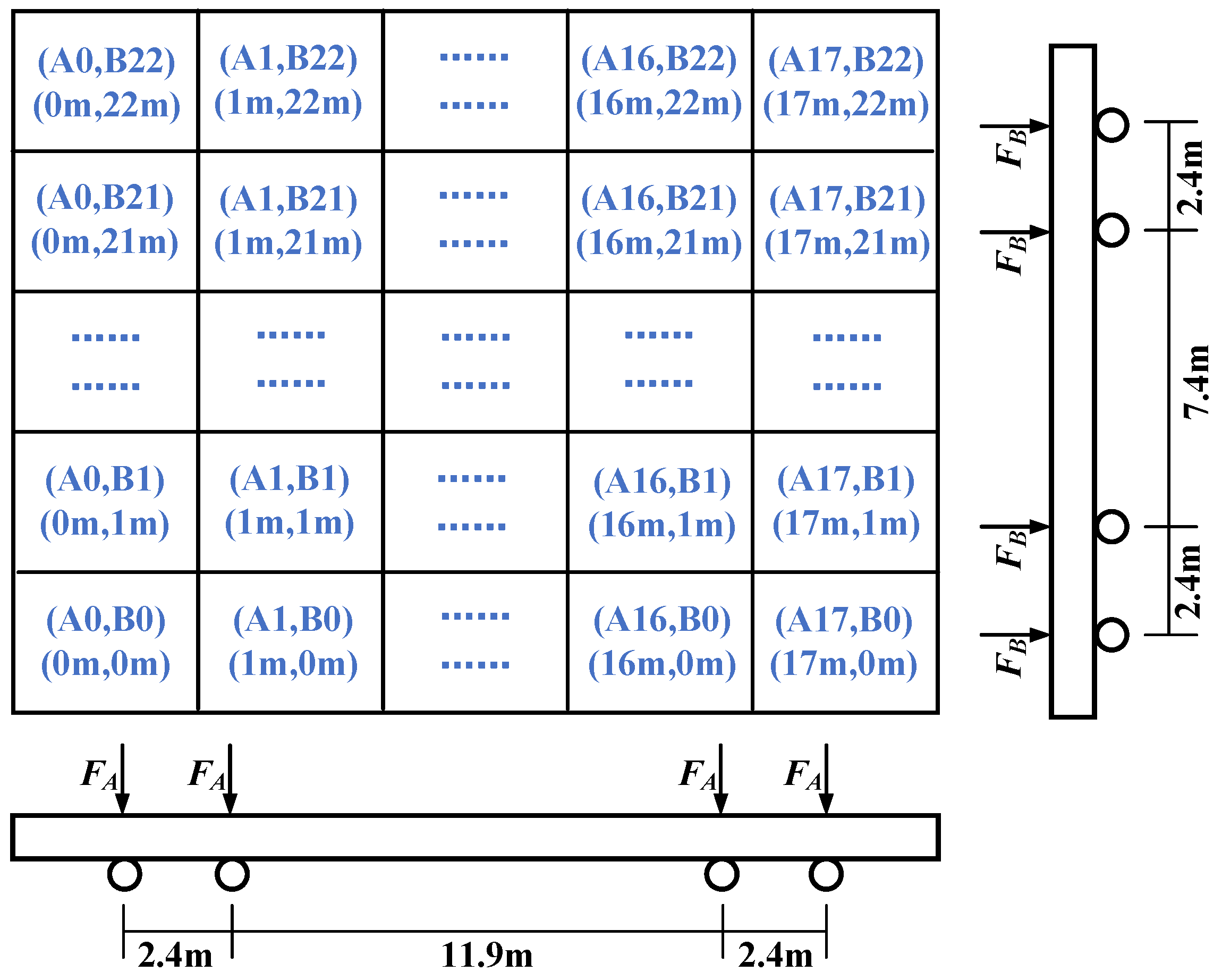
- The wheel load starts from the leftmost position and moves from left to right.
- Different load conditions are denoted as A0 to A22, each separated by 1 m intervals.
- The wheel load starts from the leftmost position and moves from left to right.
- Different load conditions are denoted as B0 to B17, each separated by 1 m intervals.
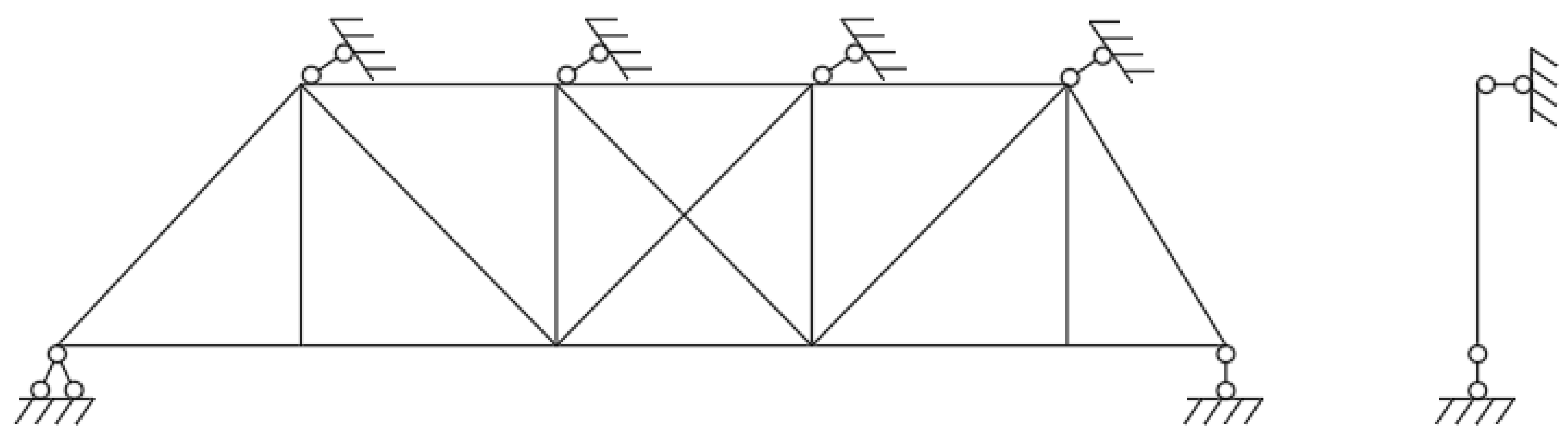
3.3. Boundary Conditions
4. Methodology
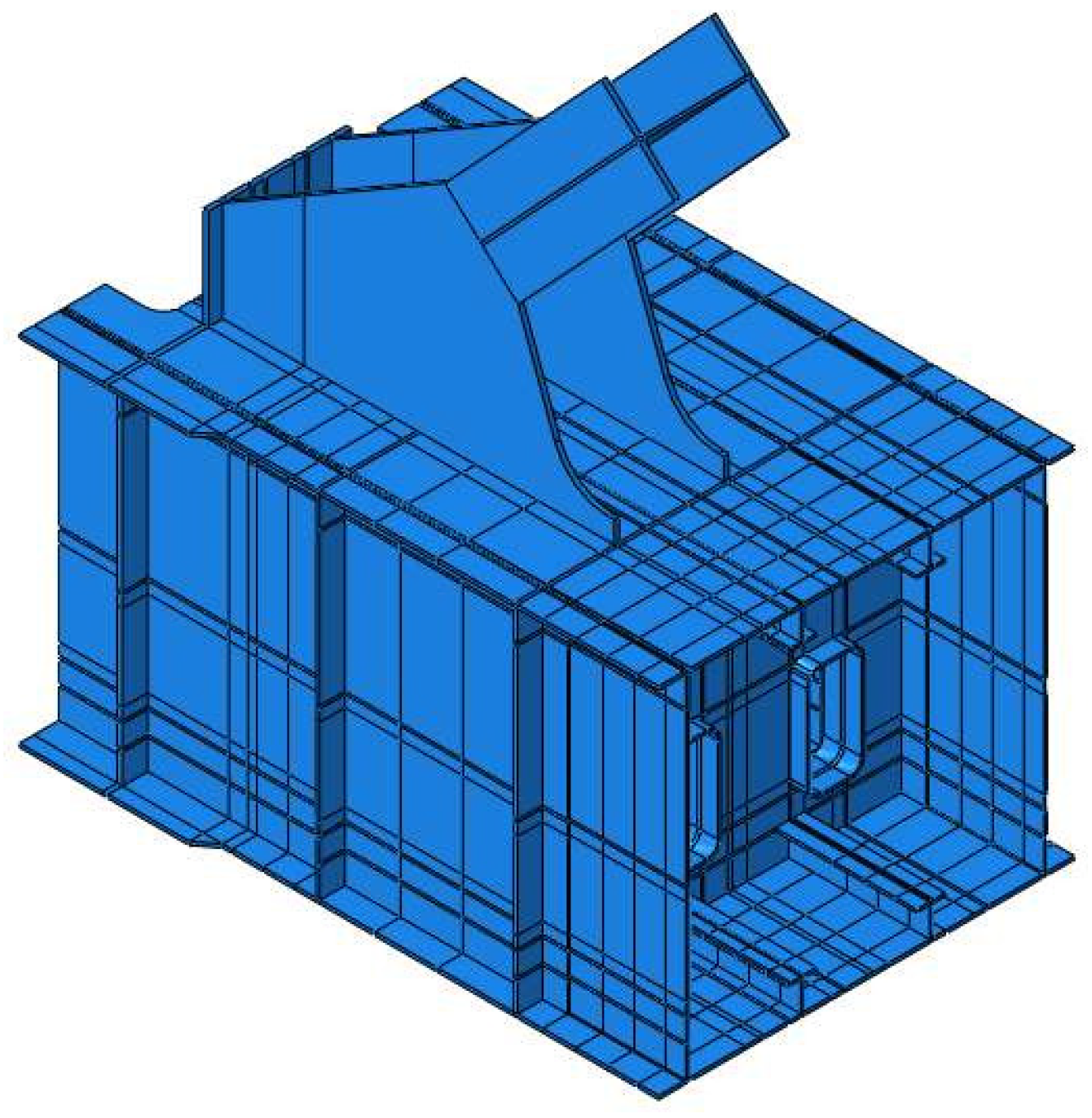
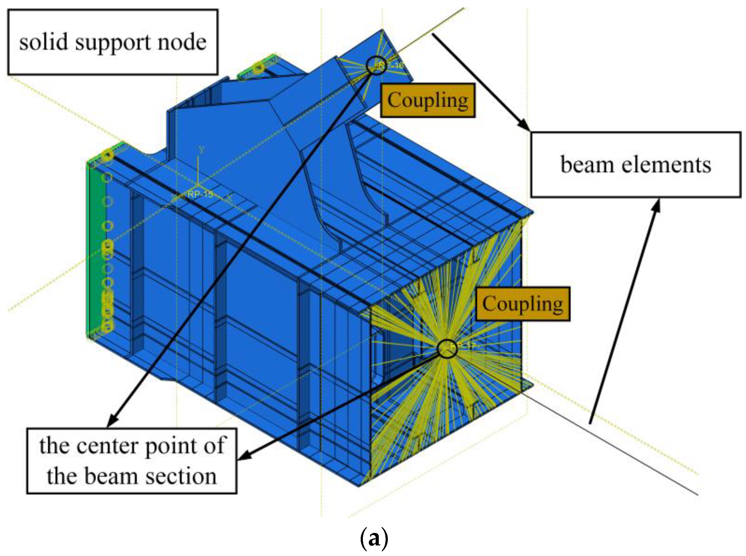
4.1. Multiscale ABAQUS Model
4.1.1. Establishing the ABAQUS Multiscale Model
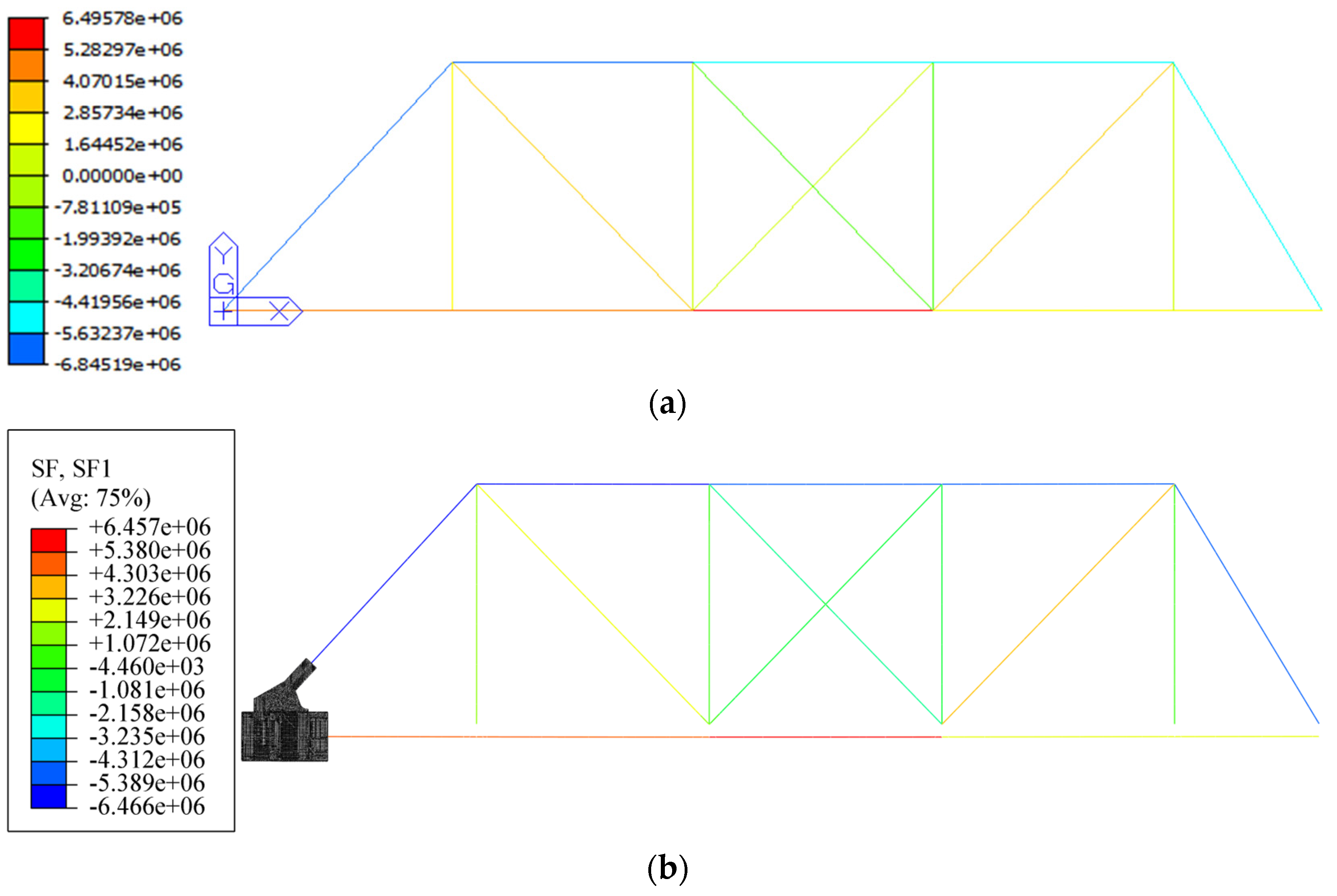
4.1.2. Comparison with the Frame Model Results
4.2. Analysis of the Load Transfer Mechanism at Lower Chord Nodes
4.2.1. Node Construction
4.2.2. Basic Assumptions
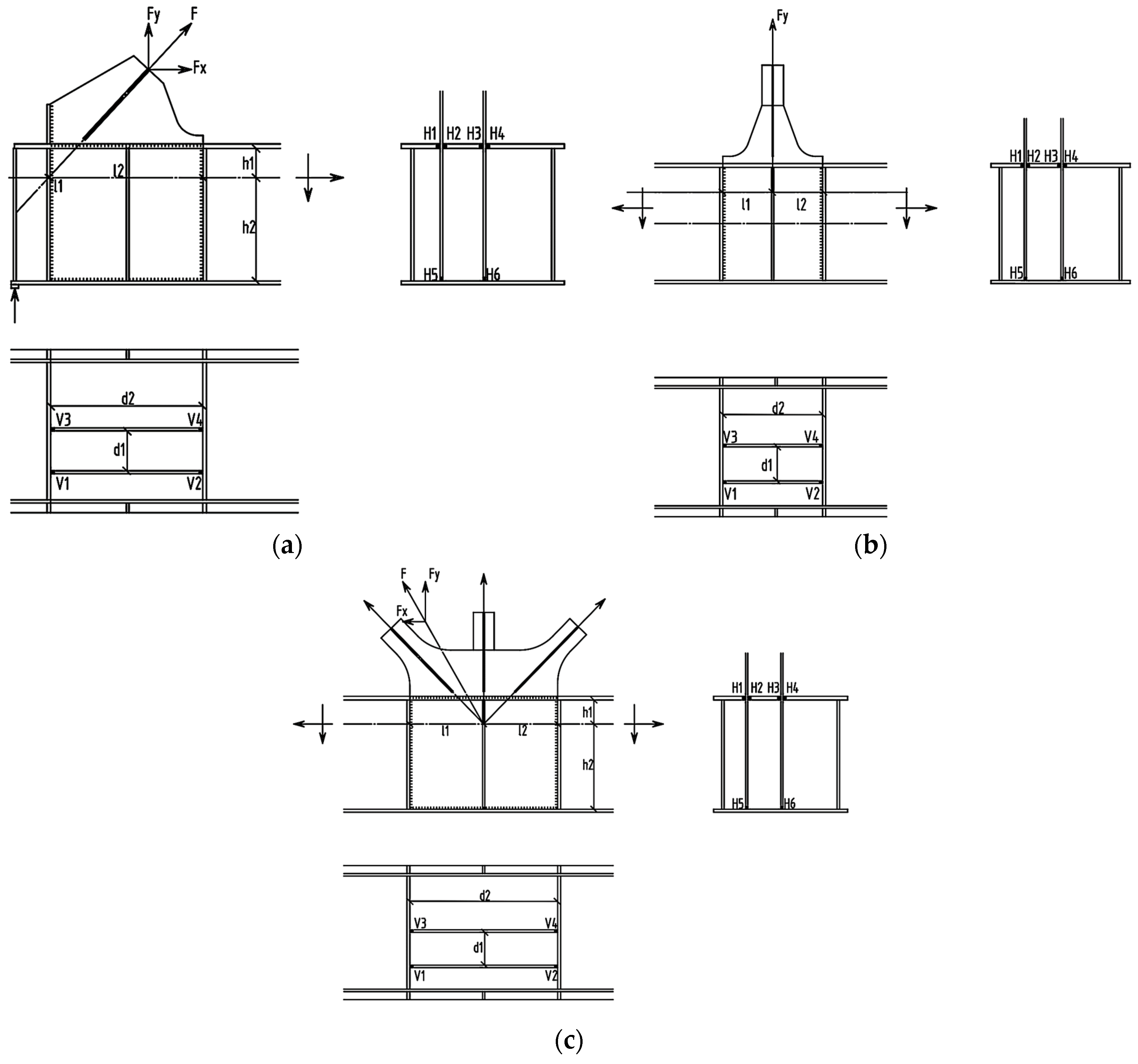
4.2.3. Calculation Formulas for Weld Force Transfer in Nodes
- (1)
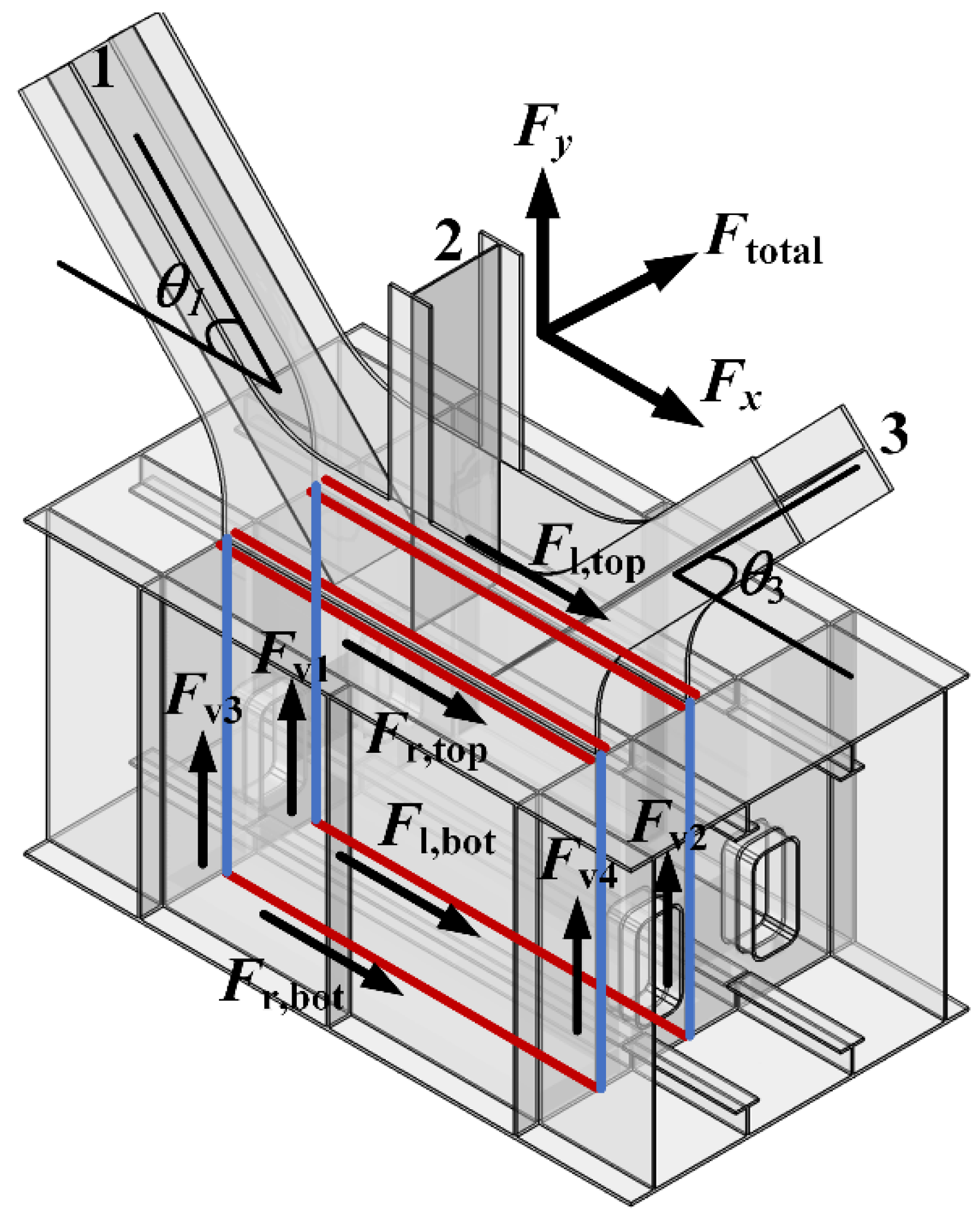
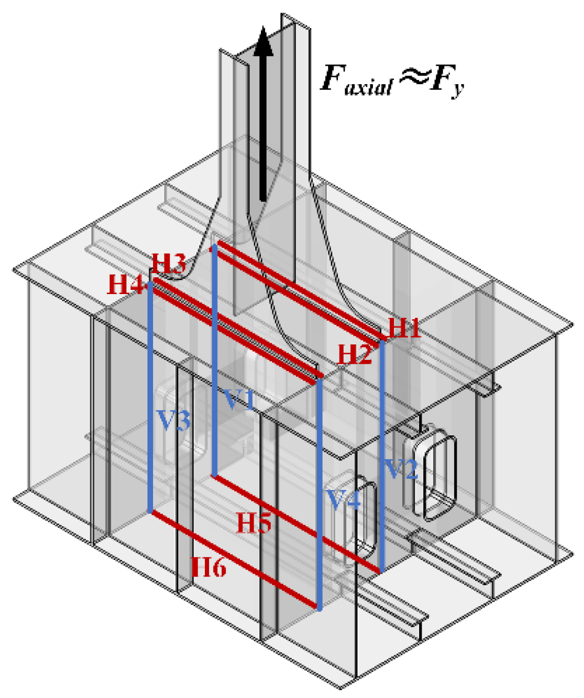
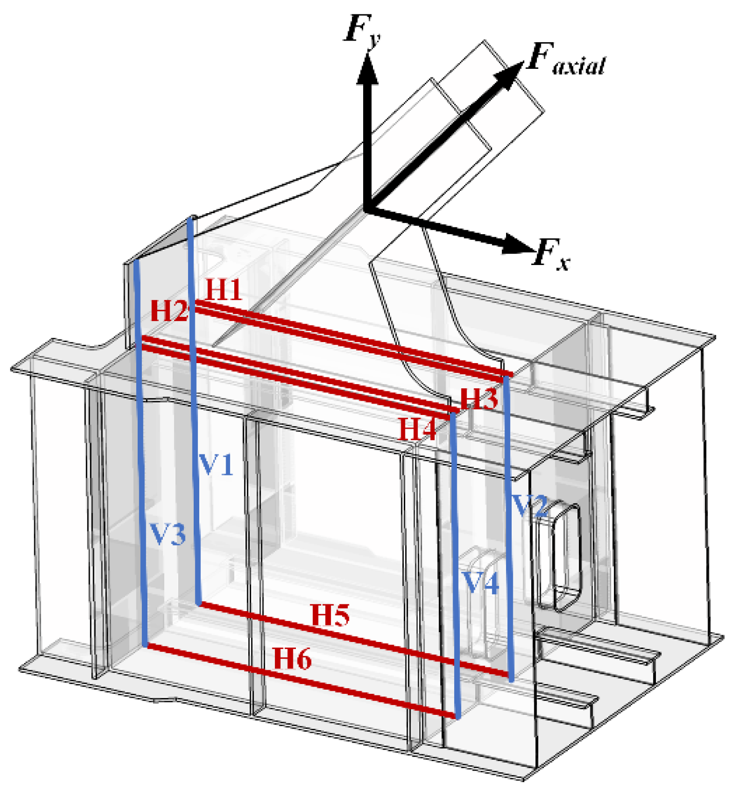
- Node with multiweb members: Figure 12 illustrates the force transmission paths of the transverse welds and vertical welds connecting the gusset plate at the node with multiweb members.
- (2)
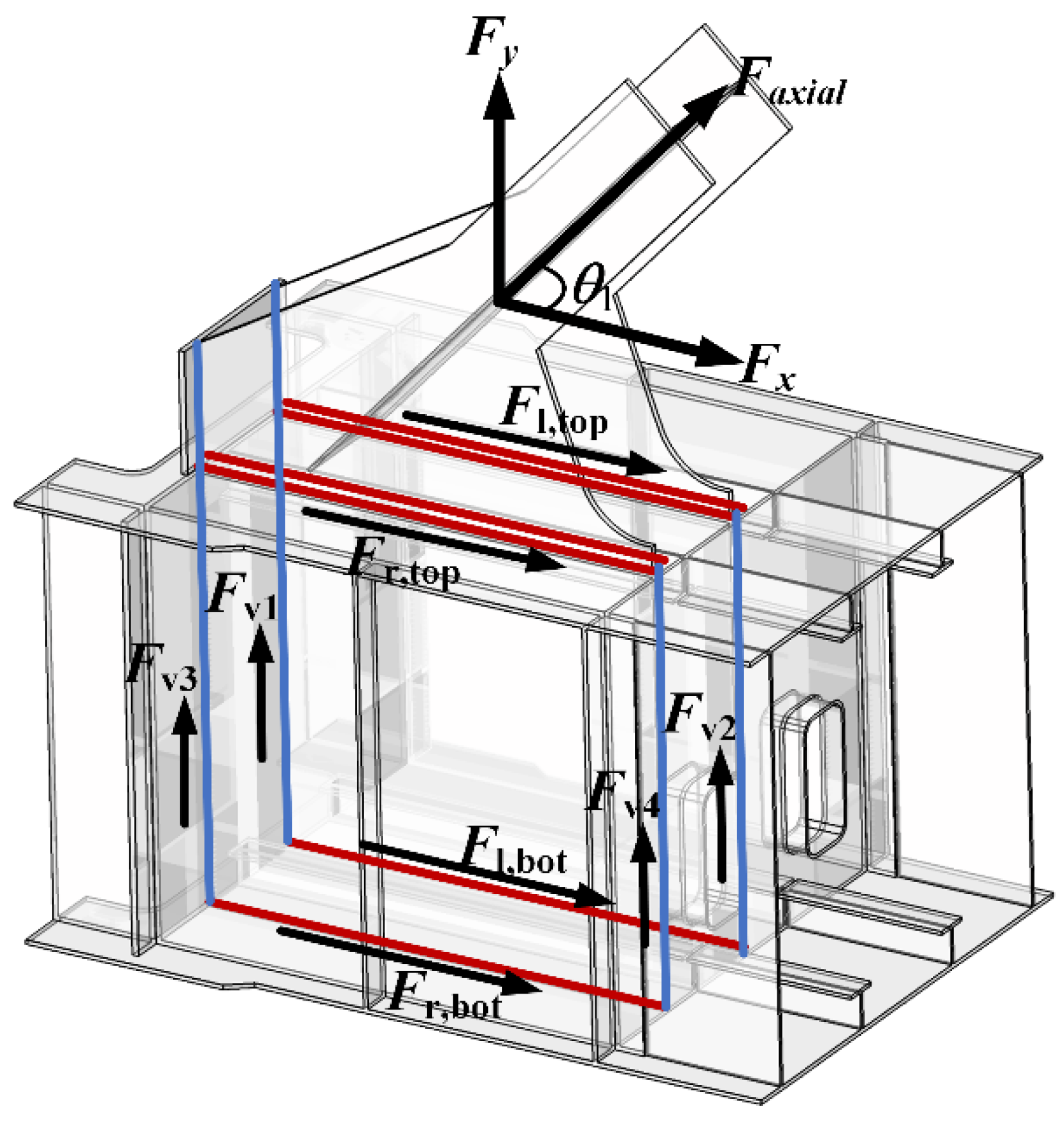
- Node with only one vertical web member: Figure 13 illustrates the force transmission paths of the node with only one vertical web member.
- (3)
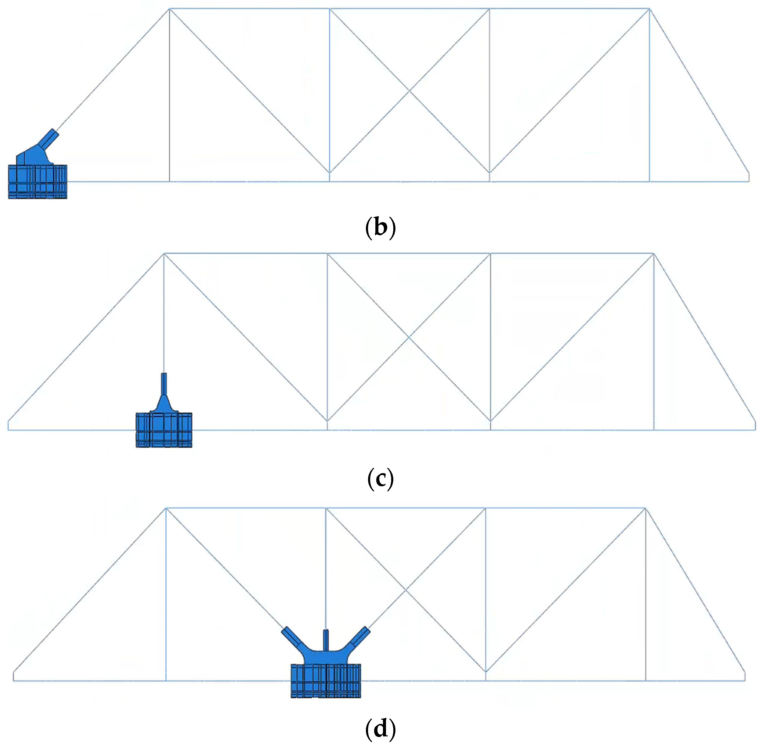
- Lower chord support nodes: Figure 14 illustrates the force transmission paths of the lower chord support nodes:
5. Discussion
5.1. Validation of Force Transmission Paths
- 1.
- Node with multiweb members
- 2.
- Node with only one web member
- 3.
- Left Support Node
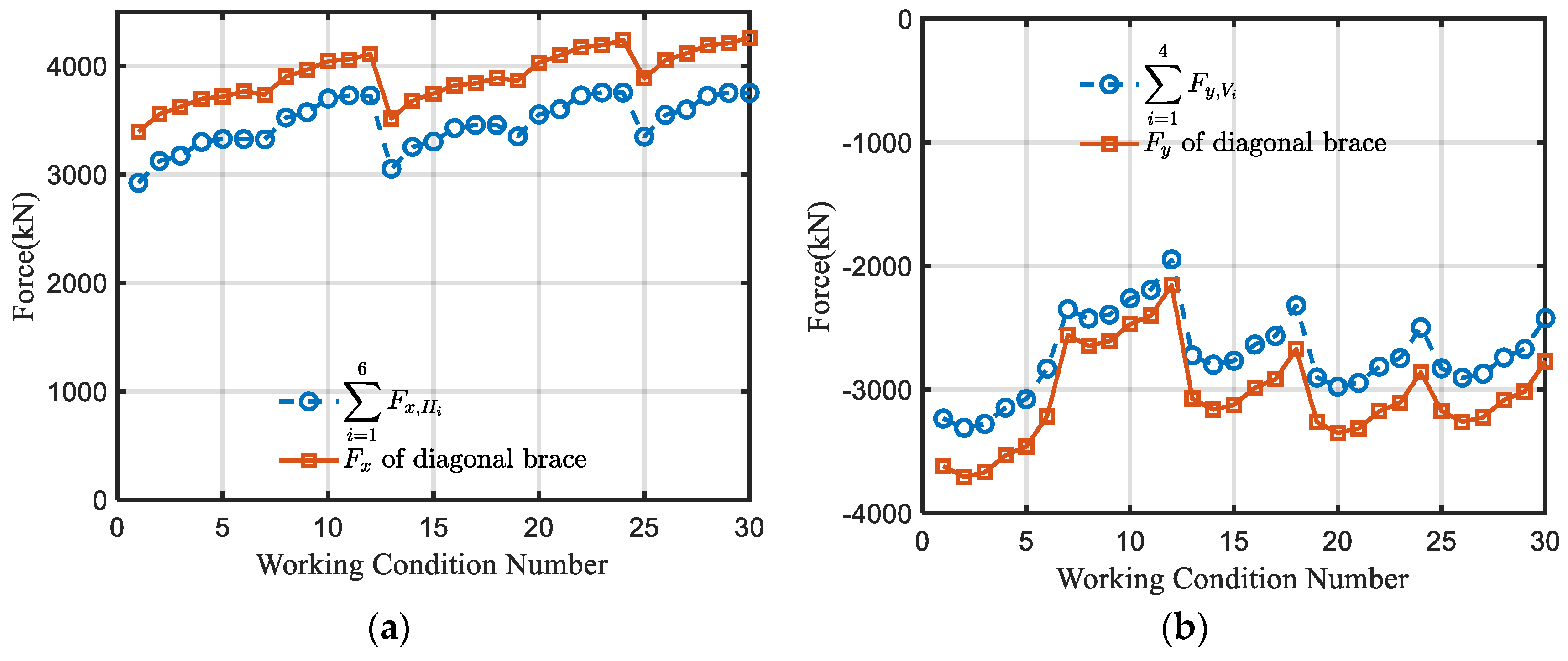
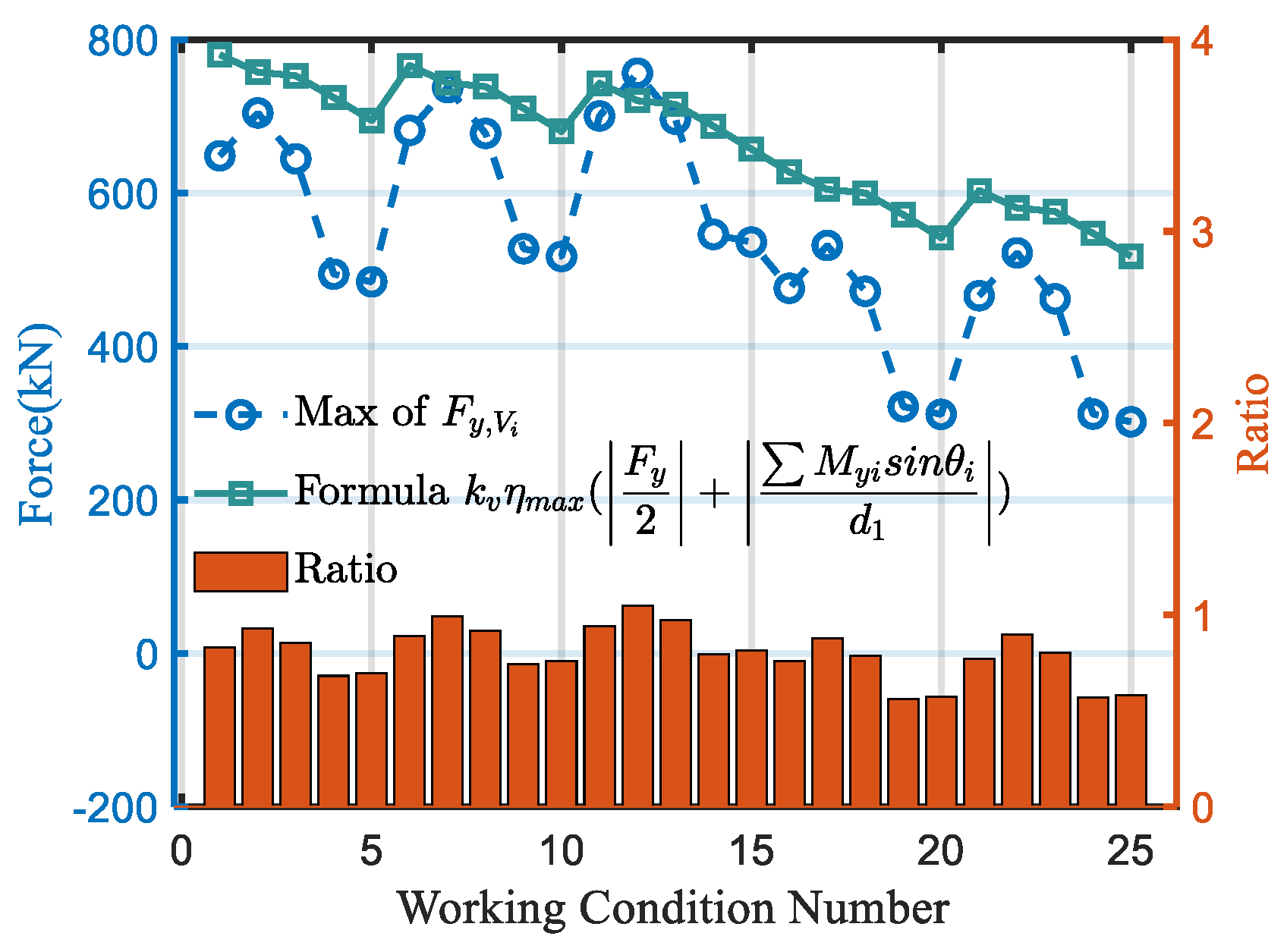
5.2. Verification of Simplified Transmission Calculation Formulas
6. Future Work
7. Conclusions
- (1)
- The study establishes a frame model and ABAQUS multiscale models, utilizing engineering project drawings and data, verifying the similarities between the two simulation methods, providing a theoretical basis for designing using a frame model.
- (2)
- The derivation of force transmission formulas for various welds in the lower chord nodes of the bracket-crane truss, from a structural mechanics standpoint based on appropriate assumptions, establishes a connection between the internal forces of interconnected chord members and the force transmission values of the welds.
- (3)
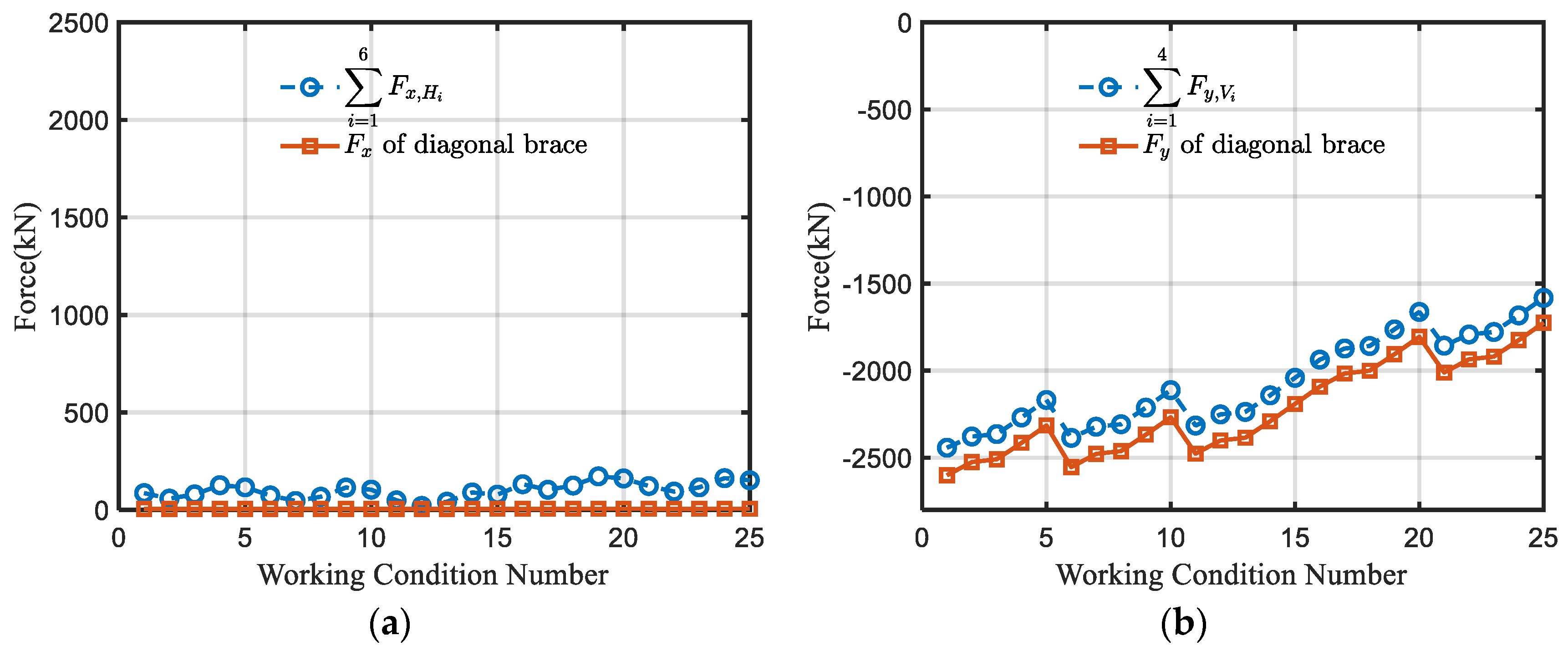
- The investigation of three types of lower chord nodes in the bracket-crane truss, using a multiscale finite element model under diverse conditions, affirms the force transmission patterns in the lower chord nodes. Specifically, horizontal welds transmit horizontal forces, while vertical welds transmit the entire vertical force.
- (4)
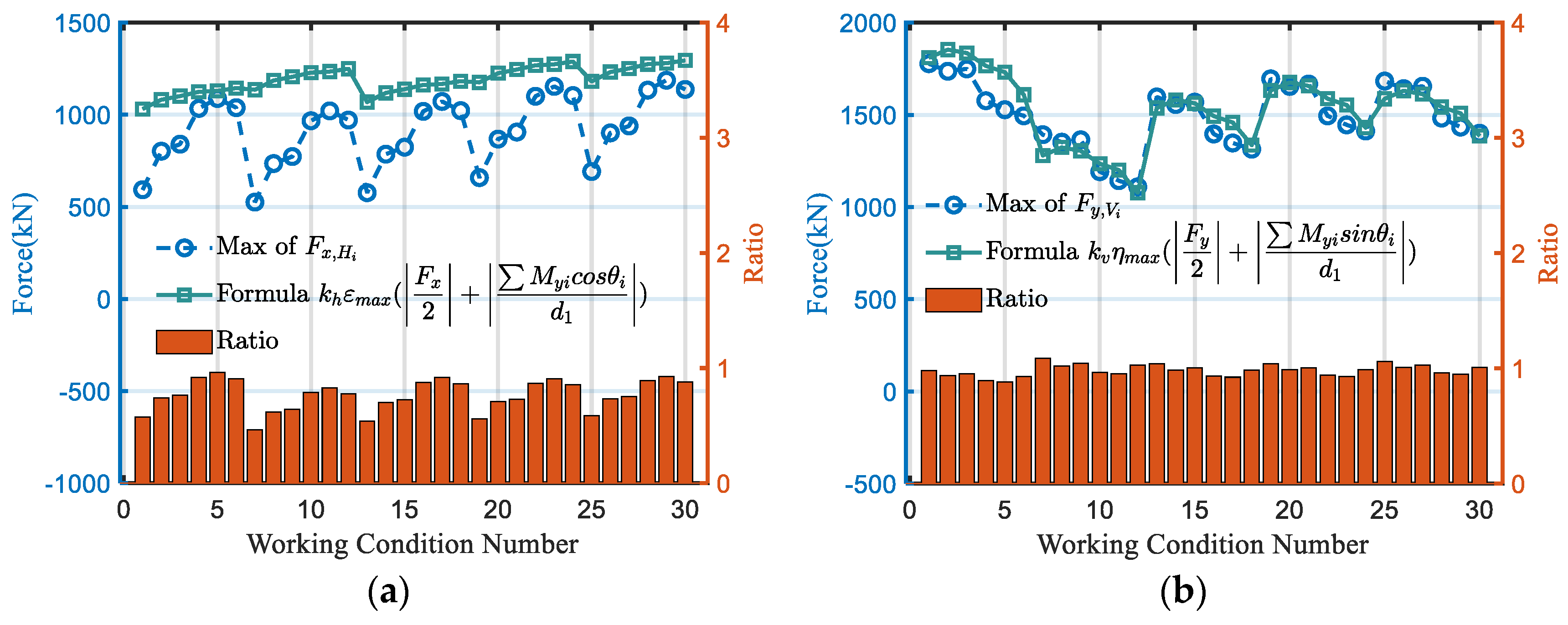
- Validation of the derived formulas for weld force transmission under various load conditions was conducted through a comparative analysis between the multiscale ABAQUS model and the simplified formula results. It is proved that the accuracy of the proposed formula can be applied in engineering.
Author Contributions
Funding
Data Availability Statement
Conflicts of Interest
Nomenclature
| the distribution ratio of the horizontal force transmitted by the upper flange | |
| the distribution ratio of the horizontal force transmitted by the lower flange | |
| the distance from the horizontal axis to the upper flange | |
| the distance from the horizontal axis to the lower flange | |
| the sum of the forces transmitted by H1 and H2 as annotated in Figure 12 | |
| the force transmitted by H5 as annotated in Figure 12 | |
| the force transmitted by H6 as annotated in Figure 12 | |
| the horizontal component of the resultant force as annotated in Figure 12 | |
| , | the angle between the web member and the horizontal line as annotated in Figure 12. |
| the in-plane bending moment of web member 1 | |
| the in-plane bending moment of web member 3 | |
| d1 | the distance between two gusset plates as shown in Figure 11 |
| the safety factor for the horizontal weld force transmission | |
| the maximum value of the horizontal weld force transmission | |
| the larger value between the distribution coefficients and . | |
| the distribution ratio of the vertical force transmitted by the left vertical weld | |
| the distribution ratio of the vertical force transmitted by the right vertical weld | |
| the distance from the left transverse plate to the vertical axis as annotated in Figure 12 | |
| the distance from the right transverse plate to the vertical axis as annotated in Figure 12 | |
| the vertical component of the force in the weld Vi as annotated in Figure 12 | |
| the vertical component of the resultant force as annotated in Figure 12. | |
| the nonuniformity coefficient of internal forces | |
| maximum value of the force transmission for the vertical weld | |
| the larger value between the distribution coefficients and . |
References
- Eremin, K.I.; Shulga, S.N. Modelirovanie razvitiya ustalostnykh povrezhdeniy v podkranovo-podstropil’nykh fermakh. Proc. Mosc. State Univ. Civ. Eng. 2014, 2, 30–38. (In Russian) [Google Scholar]
- Nikitina, E.A.; Khazov, P.A.; Brickel, D.M. Determination of residual life of crane truss taking into account damage accumulation in real operating conditions. Volga Reg. Sci. J. 2018, 1, 9–14. (In Russian) [Google Scholar]
- Tusnina, O.A. Finite element analysis of crane secondary truss. Mag. Civ. Eng. 2018, 1, 68–89. [Google Scholar]
- Euler, M.; Taylor, C. Fatigue action on crane runway beams. J. Constr. Steel Res. 2021, 181, 106476. [Google Scholar] [CrossRef]
- Euler, M.; Kuhlmann, U. Crane runways—Fatigue evaluation of crane rail welds using local concepts. Int. J. Fatigue 2011, 33, 1118–1126. [Google Scholar] [CrossRef]
- Zai, J.; Cao, J.; Bell, A.J. The fatigue strength of box girders in overhead travelling cranes. Int. J. Fatigue 1996, 72, 401–405. [Google Scholar] [CrossRef]
- Shulga, S.N. Residual Resource of Crane Trusses with an Uncut Bottom Girdle at the Stage of Fatigue Crack Growth. Ph.D. Thesis, National Research Moscow State Construction University, Moscow, Russia, 2015. [Google Scholar]
- Rettenmeier, P.; Roos, E.; Weihe, S. Fatigue analysis of multiaxially loaded crane runway structures including welding residual stress effects. Int. J. Fatigue 2016, 82, 179–187. [Google Scholar] [CrossRef]
- Wu, B.; Tang, Y.; Li, Z.; Tang, K. Fatigue damage accumulation modelling of critical components subjected to moving crane loads in reinforced-concrete industrial buildings. Eng. Fail. Anal. 2021, 119, 104951. [Google Scholar] [CrossRef]
- Tan, H.; Hu, X.; Wu, X.; Zeng, Y.; Tu, X.; Xu, X.; Qian, J. Initial crack propagation of integral joint in steel truss arch bridges and its fatigue life accession. Eng. Fail. Anal. 2021, 130, 105777. [Google Scholar] [CrossRef]
- Vičan, J.; Gocál, J.; Odrobiňák, J.; Koteš, P. Analysis of existing steel railway bridges. Procedia Eng. 2016, 156, 507–514. [Google Scholar] [CrossRef]
- Ye, X.W.; Su, Y.H.; Han, J.P. A state-of-the-art review on fatigue life assessment of steel bridges. Math. Probl. Eng. 2014, 2014, 956473. [Google Scholar] [CrossRef]
- Lehner, P.; Krejsa, M.; Pařenica, P.; Křivý, V.; Brožovský, J. Fatigue damage analysis of a riveted steel overhead crane support truss. Int. J. Fatigue 2019, 128, 105190. [Google Scholar] [CrossRef]
- Wöhler, A. Ueber die Festigkeits-Versuche mit Eisen und Stahl. 1870. Retrieved from the Digital Public Library of America. Available online: http://catalog.hathitrust.org/Record/011617584 (accessed on 11 May 2024).
- Basquin, O.H. The exponential law of endurance tests. Proc. Am. Soc. Test Mater. 1910, 10, 625–630. [Google Scholar]
- Miner, M.A. Cumulative damage in fatigue. J. Appl. Mech. 1945, 12, A159–A164. [Google Scholar] [CrossRef]
- Fisher, J.W.; Frank, K.H.; Hirt, M.A.; McNamee, B.M. Effect of Weldments on the Fatigue Strength of Steel Beams; Final Report; Lehigh University: Bethlehem, PA, USA, 1969. [Google Scholar]
- Susmel, L. Nominal stresses to assess damage in notched additively manufactured steel subjected to constant and variable amplitude multiaxial fatigue loading. Procedia Struct. Integr. 2021, 34, 178–183. [Google Scholar] [CrossRef]
- Savaidis, G.; Vormwald, M. Hot-spot stress evaluation of fatigue in welded structural connections supported by finite element analysis. Int. J. Fatigue 2000, 22, 85–91. [Google Scholar] [CrossRef]
- Han, S.-J.; Shin, B.-C. The use of hot spot stress for estimating the fatigue strength of welded components. Steel Res. 2000, 71, 466–473. [Google Scholar] [CrossRef]
- Sonsino, C.M. Comparison of different local design concepts for the structural durability assessment of welded offshore k-nodes. Int. J. Fatigue 2012, 34, 27–34. [Google Scholar] [CrossRef]
- Alencar, G.S.; Ferreira, G.; de Jesus, A.M.; Calçada, R. Fatigue assessment of a high-speed railway composite steel-concrete bridge by the hot-spot stress method. Int. J. Struct. Integr. 2018, 9, 337–354. [Google Scholar] [CrossRef]
- Tong, L.; Chen, K.; Xu, G.; Zhao, X. Formulae for hot-spot stress concentration factors of concrete-filled chs t-joints based on experiments and fe analysis. Thin-Walled Struct. 2019, 136, 113–128. [Google Scholar] [CrossRef]
- Zhu, Q.; Lu, P.; Xiang, Q. Fatigue life evaluation of web butt welding structure on boom of excavator by hot spot stress approach. Eng. Fail. Anal. 2020, 113, 104547. [Google Scholar] [CrossRef]
- Zhou, F.; Chen, Y.; Wang, W.; Xie, W.; Ying, T.; Yue, G. Investigation of hot spot stress for welded tubular k-joints with stiffeners. J. Constr. Steel Res. 2022, 197, 107452. [Google Scholar] [CrossRef]
- Sonsino, C.; Fricke, W.; de Bruyne, F.; Hoppe, A.; Ahmadi, A.; Zhang, G. Notch stress concepts for the fatigue assessment of welded joints—Background and applications. Int. J. Fatigue 2012, 34, 2–16. [Google Scholar] [CrossRef]
- Neuber, H. Theory of stress concentration for shear-strained prismatical bodies with arbitrary nonlinear stress-strain law. J. Appl. Mech. 1961, 28, 544–550. [Google Scholar] [CrossRef]
- Berto, F.; Lazzarin, P. Fictitious notch rounding approach of pointed v-notch under in-plane shear. Theor. Appl. Fract. Mech. 2010, 53, 127–135. [Google Scholar] [CrossRef]
- Alencar, G.; Hong, J.K.; de Jesus, A.; da Silva, J.G.S.; Calçada, R. The master s-n curve approach for fatigue assessment of welded bridge structural details. Int. J. Fatigue 2021, 152, 106432. [Google Scholar] [CrossRef]
- Dong, P. A structural stress definition and numerical implementation for fatigue analysis of welded joints. Int. J. Fatigue 2001, 23, 865–876. [Google Scholar] [CrossRef]
- Hong, J.K.; Forte, T.P. Fatigue evaluation procedures for bi-axial loaded plate joints using the battelle structural stress method. Procedia Eng. 2015, 133, 410–419. [Google Scholar] [CrossRef]
- Jia, D.; Zhang, Q.; Xiong, L.; Li, J.; Bu, Y.; Bao, Y. A unified evaluation method for fatigue resistance of riveted joints based on structural stress approach. Int. J. Fatigue 2022, 160, 106871. [Google Scholar] [CrossRef]
- Citarella, R.; Perrella, M. Multiple surface crack propagation: Numerical simulations and experimental tests. Fatigue Fract. Eng. Mater. Struct. 2005, 28, 135–148. [Google Scholar] [CrossRef]
- Smith, I.; Smith, R. Fatigue crack growth in a fillet welded joint. Eng. Fract. Mech. 1983, 18, 861–869. [Google Scholar] [CrossRef]
- Schott, G.; Donat, B.; Schaper, M. THE consecutive wöhler curve approach to damage accumulation. Fatigue Fract. Eng. Mater. Struct. 1996, 19, 373–385. [Google Scholar] [CrossRef]
- Susmel, L. On the use of the modified wöhler curve method to estimate notch fatigue limits*. Mater. Test. 2006, 48, 27–35. [Google Scholar] [CrossRef]
- Mashayekhi, M.; Santini-Bell, E. Three-dimensional multiscale finite element models for in-service performance assessment of bridges. Comput.-Aided Civ. Infrastruct. Eng. 2019, 34, 385–401. [Google Scholar] [CrossRef]
- Mashayekhi, M.; Santini-Bell, E. Fatigue assessment of a complex welded steel bridge connection utilizing a three-dimensional multi-scale finite element model and hotspot stress method. Eng. Struct. 2020, 214, 110624. [Google Scholar] [CrossRef]
- Luo, P.; Zhang, Q.; Bao, Y.; Bu, Y. Fatigue performance of welded joint between thickened-edge u-rib and deck in orthotropic steel deck. Eng. Struct. 2019, 181, 699–710. [Google Scholar] [CrossRef]


| Structural Components | Cross-Sectional Profiles | Material | Elastic Modulus | Poisson’s Ratio |
|---|---|---|---|---|
| Diagonal bracing at the edge | H800 × 700 × 20 × 35 | Q355C | 210,000 MPa | 0.3 |
| Diagonal bracing | H800 × 600 × 16 × 30 | |||
| Vertical bracing | H800 × 350 × 16 × 25 | |||
| Upper chord box beam | H800 × 800 × 20 × 25 |
| Load Types | Standard Value | Partial Load Factors | |
|---|---|---|---|
| Strength and Stability | Fatigue | ||
| Self-weight | 9.8 × Mass | 1.3 | - |
| Roof Dead Load (Applied as Nodal Forces) | 300 kN | 1.3 | - |
| Roof Live Load (Applied as Nodal Forces) | 250 kN | 1.5 | - |
| Crane Load on Span A | 1568 kN for one crane | 1.5 (two cranes adjacent) | - |
| Crane Load on Span B | 1548 kN for one crane | 1.5 (two cranes adjacent) | 1.3 (one crane) |
Disclaimer/Publisher’s Note: The statements, opinions and data contained in all publications are solely those of the individual author(s) and contributor(s) and not of MDPI and/or the editor(s). MDPI and/or the editor(s) disclaim responsibility for any injury to people or property resulting from any ideas, methods, instructions or products referred to in the content. |
© 2024 by the authors. Licensee MDPI, Basel, Switzerland. This article is an open access article distributed under the terms and conditions of the Creative Commons Attribution (CC BY) license (https://creativecommons.org/licenses/by/4.0/).
Share and Cite
Zhao, H.; Li, S.; Guo, Z.; Dong, C.; Fan, J.; Tao, L.; Zhang, W. Simplified Formula for Nominal Force at Critical Welds in the Lower Chord Node of a Novel Bracket-Crane Truss Structure. Buildings 2024, 14, 1994. https://doi.org/10.3390/buildings14071994
Zhao H, Li S, Guo Z, Dong C, Fan J, Tao L, Zhang W. Simplified Formula for Nominal Force at Critical Welds in the Lower Chord Node of a Novel Bracket-Crane Truss Structure. Buildings. 2024; 14(7):1994. https://doi.org/10.3390/buildings14071994
Chicago/Turabian StyleZhao, He, Shuaiyu Li, Zhongyan Guo, Chao Dong, Jiangtao Fan, Lipeng Tao, and Wenyuan Zhang. 2024. "Simplified Formula for Nominal Force at Critical Welds in the Lower Chord Node of a Novel Bracket-Crane Truss Structure" Buildings 14, no. 7: 1994. https://doi.org/10.3390/buildings14071994