Article

Simplified Formula for Nominal Force at Critical Welds in the Lower Chord Node of a Novel Bracket-Crane Truss Structure

1
Capital Engineering & Research Incorporation Limited, Beijing 100176, China
2
Key Lab of Structures Dynamic Behavior and Control of the Ministry of Education, Harbin Institute of Technology, Harbin 150090, China
3
Key Lab of Smart Prevention and Mitigation of Civil Engineering Disasters of the Ministry of Industry and Information Technology, Harbin Institute of Technology, Harbin 150090, China
*
Authors to whom correspondence should be addressed.
Buildings 2024, 14(7), 1994; https://doi.org/10.3390/buildings14071994
Submission received: 11 May 2024 / Revised: 18 June 2024 / Accepted: 28 June 2024 / Published: 1 July 2024
(This article belongs to the Section Building Structures)

Abstract

:
In the realm of practical engineering, engineers commonly employ rod system models for modeling and analysis, which consequently precludes them from calculating the nominal forces exerted on welds at intricate nodes. This paper addresses the design challenges of the innovative bracket-crane truss structure by proposing a simplified nominal force calculation formula for critical welds of the integrated node. This study commences with the establishment of the frame model and ABAQUS multiscale models, utilizing engineering project drawings and data, followed by a verification of the similarities between the two simulation methods. This similarity of outcomes provides a foundation for directly using the computational results from the frame model in future calculations of the forces at the weld locations. From a mechanical standpoint, this paper derives nominal force calculation formulas for horizontal and vertical welds at critical locations for three node types. Additionally, a formula for calculating nominal shear forces in vertical welds at the end plate of support nodes is introduced. The applicability of these derived formulas is subsequently validated, ensuring their efficacy in accurately capturing relevant forces at critical locations. The presented nominal force calculation formula serves as a valuable tool for optimizing the design and guaranteeing the structural integrity of the integrated node within this distinctive engineering context.

1. Introduction

Large-scale workshops, such as those in the iron and steel metallurgical industry, often require vast open spaces devoid of obstructive beams or columns to facilitate production processes. This necessitates expansive architectural floor plans and ample clear heights to accommodate complex machinery and workflows. Specifically, the medium-thick plate rolling process demands a column-free span of 57.5 m or greater in the cold bed area to satisfy production needs. To address this requirement for large spans, domestic design entities traditionally employ solid-web crane beams, which, with a sectional height often exceeding 6 m, present significant challenges in terms of transportation and on-site assembly. The use of such beams in the cold bed area not only compromises the net height of the space but also impacts visibility. Furthermore, the need for thermal insulation beneath these beams encroaches upon the valuable bottom clear space, exacerbating the issue. Factories of this nature, characterized by large spans and extensive column spacing, also require robust support structures to bear the weight of roof trusses and the roofing material itself, in addition to the load of crane beams with substantial spans. In a steel rolling heavy plate factory, for instance, the standard column spacing in the cold bed area is typically 12 m, occasionally interspersed with 15 m spacings. This configuration is chosen to align with the process equipment layout and to optimize steel usage, as it is most economical at this spacing. In the cold bed equipment zone, it may be necessary to remove several columns to achieve a span of 48 to 60 m, aligning with the equipment’s layout requirements and accommodating crane passage. Large-span crane beams designed to handle heavy loads often necessitate a substantial sectional height, as depicted in Figure 1a. This can reduce the effective clear space beneath the beams. Alternatively, to maintain this clear space, the elevation of the crane beam may need to be raised, which in turn increases the overall factory height and construction costs. For example, in 1988, at the Bao-steel Up-steel No. 3 Plant’s heavy plate workshop cold bed area, the space below the crane rail had to be occupied. When the crane truss span is large, it severely affects the usable space in the workshop.
Therefore, it is feasible to consider integrating the support structure and the crane truss, enabling it to serve as a support for both the intermediate roof trusses and the crane rails, forming what is known as a bracket-crane truss structure. Employing this structure can significantly enhance the economic efficiency of the factory’s structural design. In heavy plate rolling mills, the span of crane beams in the cooling bed area can reach 57.5 m or more. Under such spans, the preliminary calculation for the steel quantity required by the bracket-crane truss structure is approximately 235 tons, while the solid-web crane beam structure would be about 282 tons. Considering the example of an 8-set ultra-large span crane beam in a heavy plate workshop, adopting a bracket-crane truss structure can save approximately 370 tons of steel. Typically, the spacing of the upper chord nodes of this type of truss should be equal to the spacing of the intermediate roof trusses, with the upper chord nodes serving as supports for the roof trusses to bear the roof load. Meanwhile, the lower chord’s upper surface is fitted with crane rails to bear the load of the crane. This form of structure has been used in reality, as shown in Figure 1b. This type of bracket-crane truss structure not only has a large span but also simultaneously bears the roof load and the crane load, resulting in a complex stress state for the members and spatial stress effects at the node details. When designing, it is necessary to consider the structure’s static strength, stability, and fatigue strength simultaneously.
The current research on the novel bracket-crane truss structure is predominantly concentrated in Russia, as indicated by references [1,2,3]. In 2014, Eremin et al. [1] predicted the fatigue life and structural viability of bracket-crane truss structures. They accomplished this by calculating the stress-strain state of these structures in the oxygen converter shop of the Magnitogorsk Metallurgical Plant, utilizing finite element simulations based on damage statistics. In 2018, Nikitina et al. [2] proposed a theoretical method for determining the remaining life of bracket-crane truss structures. This method is grounded in existing test data and employs a damage accumulation model. The analysis was performed on bracket-crane truss structures within the production building of a metallurgical enterprise’s foundry, where the method’s feasibility was confirmed. In the same year, Tusnina [3] critically examined the limitations of using beam finite elements in modeling bracket-crane truss structures. Through finite element analysis, they identified the reasons for inaccurate results and proposed the use of shell finite elements to estimate the trusses’ load-carrying capacity, taking into account the actual condition of the structure and the specific location of defects.
Cranes are indispensable in industrial settings for material handling [4]. These machines are designed to lift, lower, and move loads horizontally along rails secured to the main structure, particularly in light- and medium-duty applications [5]. The incessant motion of cranes, along with the routine lifting and lowering of loads, leads to fluctuating internal stresses within the crane beams. Even when the steel conforms to the strength specifications for diverse loads, the potential for fatigue failure remains considerable [6].
In 2015, Shulga [7] proposed a method for estimating the remaining life of bracket-crane trusses during the fatigue crack growth stage. The study delved into the fatigue development patterns of bracket-crane trusses, offering insights and recommendations for inspection and maintenance during the fatigue crack accumulation stage. Additionally, Rettenmeier [8] in 2016 outlined a fatigue assessment procedure, evaluating the impact of multiaxial stress induced by traveling crane wheel loads and welding residual stresses on the lifespan of crane runway girders. In 2021, Wu [9] conducted a study on reinforced concrete (RC) beams exposed to crane-moving loads, contributing a numerical framework for predicting damage and safety assessment in structures that have endured diverse loading conditions over extended periods. Concurrently, Tan H. [10] explored the fatigue crack failure mode of welded monolithic nodes in steel truss bridges using finite element and linear elastic fracture mechanics methods. The research analyzed initial crack extension, evaluated fatigue life, and investigated the influence of different parameters on the stress intensity factor.
While there have been fewer studies on bracket-crane trusses, it is noteworthy that steel bridges face similar challenges to truss structures in industrial facilities [11,12,13]. Scholars have employed diverse methods to investigate high-cycle fatigue issues in these structures and proposed corresponding models, establishing theoretical foundations for the adoption of bracket-crane trusses.
Wöhler’s [14] foundational work established the stress range as the primary determinant of fatigue life, with stress level a secondary factor. This insight paved the way for the correlation between cycle count and stress magnitude, essential for fatigue damage prevention. Basquin [15] later formulated the linear relationship evident in the S-N curve, a cornerstone in fatigue analysis. Miner’s [16] linear cumulative damage criterion, introduced in 1945, simplified engineering calculations. Fisher [17] and colleagues, in 1970, highlighted stress amplitude Δσ as a key parameter for steel bridge fatigue performance, leading to its adoption in engineering standards. The most fundamental method for fatigue assessment in civil engineering structures is currently the nominal stress method [18]. For simple connection configurations, the structure’s fatigue life is predicted by calculating the nominal stress, employing the rainflow counting method, and applying Miner’s linear damage criterion. Through testing, the constants of the S-N curve for the entire node connection are determined, and subsequently, the fatigue life of the entire node is assessed. Given the complexity of geometries, particularly in intricate structures, and with the continuous advancement of finite element software, various stress theories have been introduced. These include the hot spot stress method [19,20,21,22,23,24,25], the notched stress method [26,27,28], the structural stress method [29,30,31,32], and the linear elastic fracture mechanics method [33,34], all aimed at analyzing the overall fatigue life of welded structures.
In summary, numerous theories and methods have been proposed for the study of high-cycle fatigue performance in the nodes and structures of bridges, trusses, and other constructions. While these offer valuable references for promoting bracket-crane trusses, civil engineering designers often face challenges in applying these methods to project design [13]. Most methods proposed are based on the local stress state, and these methods require the combination of refined finite element models, which greatly limits their use by engineers. For engineering practitioners, the simplest methods are still the nominal stress method and the hot spot stress method, which is prescribed by the related code. Given the widespread use of commercial static analysis software in the practice of steel structure design, it naturally leads to the idea of utilizing these software to establish frame models, determine the nominal stress range of corresponding components, and then combine this with the traditional concept of the Wöhler curve [35,36] for structural verification. Hence, there is a pressing need for a simplified method to calculate nominal stresses at potentially dangerous weld locations in integral weld joints, providing guidance for engineering design.

2. Aim of this Study

This paper primarily performs a stress analysis utilizing the ABAQUS multiscale model and presents a nominal force calculation formula for critical welds in the integral welded nodes of the bracket-crane truss structure. This study is structured into five parts. The second section provides an overview of the engineering background of the innovative bracket-crane truss structure. In the third part, both a frame model and a multiscale ABAQUS solid model are established, and the consistency of their outcomes is verified. The fourth part scrutinizes force transmission at the critical welds of three welded integral nodes, suggests a simplified calculation formula for weld forces, and compares the results with simulations. In the fifth part, force transmission in the vertical weld of the end plate of the support node is investigated, and a simplified calculation formula for weld shear force is proposed and validated. The proposed simplified formulas for weld force transmission provide a fundamental reference for designing bracket-crane truss structures using a frame model.

3. Engineering Background

3.1. Structural Arrangement

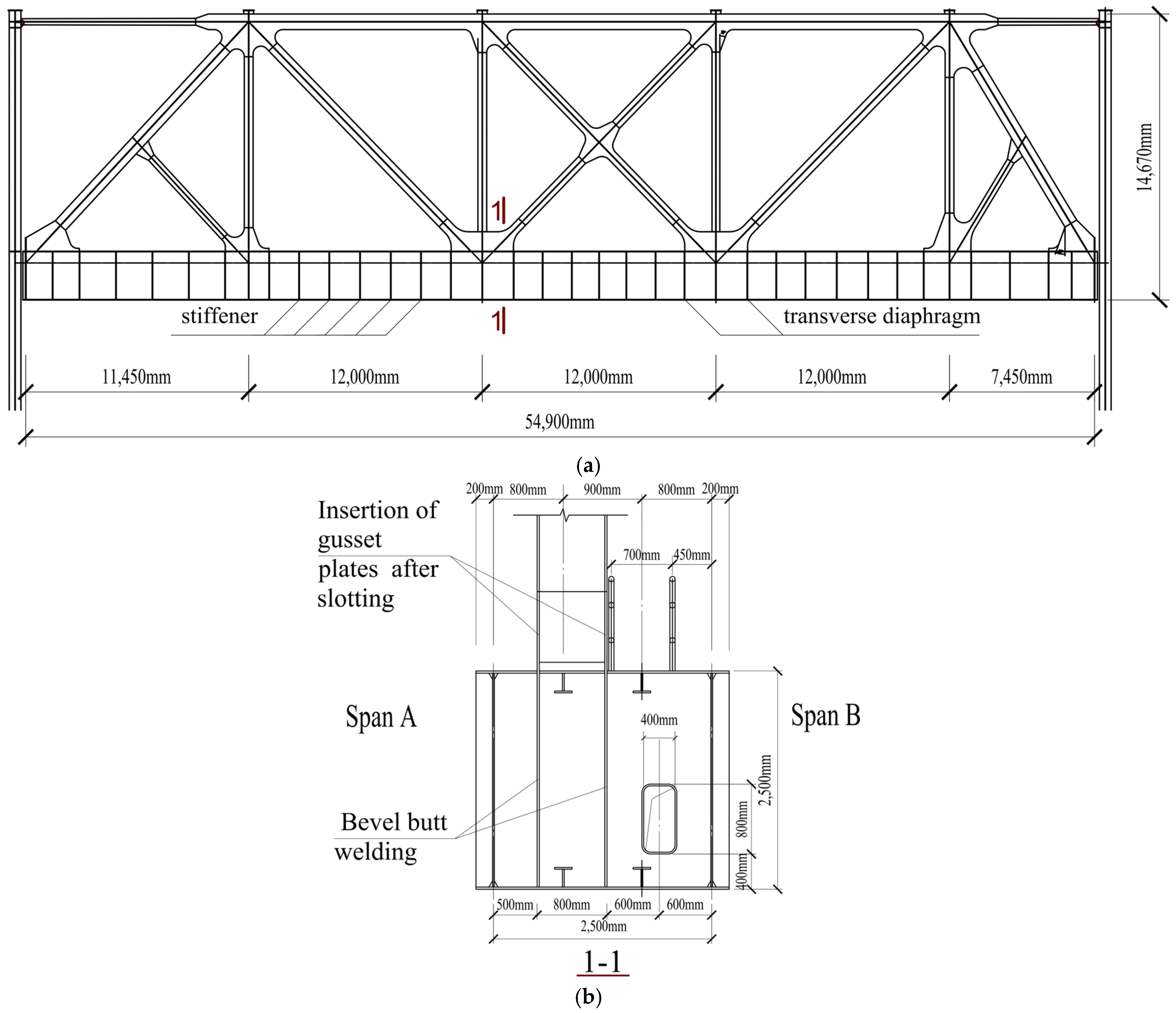
Capital Engineering & Research Incorporation Limited is proposing the implementation of an innovative bracket-crane truss structure for its Thick Plate Steel Factory. The specific dimensions are chosen for two main reasons. On one hand, it is because this is an actual engineering project that has already been constructed. Subsequent research on the issues arising from this project will be carried out, so using these specific dimensions in this study will ensure consistency with the future research. On the other hand, the goal of this research is to demonstrate the applicability of the research methods proposed. Although this particular case has been chosen, it does not hinder the use of the proposed methods. The approach remains universally applicable. The overall layout of the bracket-crane truss structure is displayed in Figure 2a. The span of this structure is 54,900 mm (11,450 + 12,000 + 12,000 + 12,000 + 7450 mm), with cranes performing reciprocating motions along the lower chord members of the truss. The overall height of the bracket-crane truss is 14,670 mm, and its lower chord members are equipped with stiffeners and transverse diaphragms. The lower chord of the bracket-crane truss is designed with a box section, while the web members and upper chord adopt an I-beam section. Figure 2b provides a detailed section view along cut line 1-1, and Figure 3 provide a detailed local enlargement of the multiweb member connected integral node. The lower chord nodes of the bracket-crane truss utilize factory-welded integral nodes, where gusset plates are inserted into slots cut in the upper flange of the box section. The gusset plates are welded to the upper flange using a combination of butt and fillet welds, and to the lower flange solely by butt welds. Transverse bulkheads are installed on both sides of the gusset plates, and vertical butt welds are used to connect the gusset plates to these bulkheads. T-shaped stiffeners are installed on both the upper and lower flanges of the box section of the lower chord members. There is an eccentricity in the design of the box section of the lower chord members, with offsets in two directions measuring 0.35 m and 0.65 m, respectively.

3.2. Sectional Information

The cross-sectional profiles and material specifications for the upper chord box beam and I-shaped bracing are consolidated in Table 1. The lower chord box beam adopts a box-shaped profile with a width of 2.9 m, a height of 2.5 m, upper and lower flange thicknesses of 25 mm, and a web thickness of 20 mm.
The load cases and load combinations for the entire bracket-crane truss are outlined in Table 2. When conducting static force analysis, it is necessary to include the self-weight of the structure, the standard value of the roof load (which has been converted into concentrated forces at the upper chord nodes), as well as the standard wheel pressure load values from the cranes on both sides. The standard value for the permanent roof load is 300 kN, and the standard value for the live roof load is 250 kN, both applied as concentrated forces at the upper chord nodes. The effect of the crane on span A is borne by four crane wheels, with each wheel having a standard load value of 392 kN. Similarly, the effect of the crane on span B is borne by four crane wheels, with each wheel having a standard load value of 387 kN.
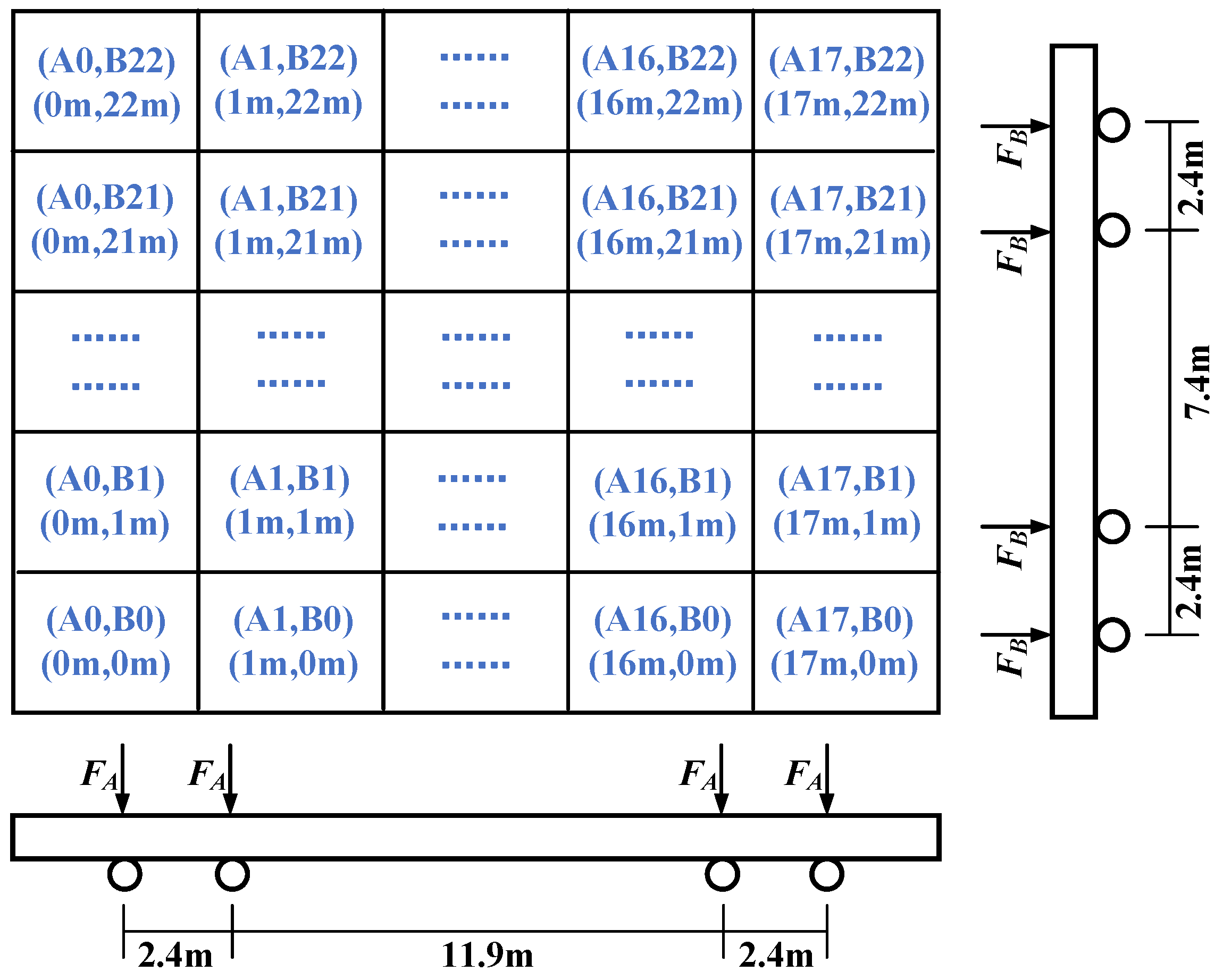
As illustrated in Figure 4, rails are installed on both sides of the box-shaped section flanges at corresponding positions to support crane loads, with eccentricities of 1.6 m and 0.9 m on the two flanges, respectively. The crane loads on the two spans are referred to as span A and span B. The A crane, which operates on span A, is equipped with four wheels spaced at intervals of 2.4 m, 11.9 m, and 2.4 m. Similarly, the B crane, operating on span B, features four wheels with a wheel spacing of 2.4 m, 7.4 m, and 2.4 m.
Due to the random movement of the cranes on both sides of the overall bracket-crane truss, making their specific positions uncertain, a comprehensive approach is adopted to account for the cranes’ different positions, as shown in Figure 5. The methodology involves
Span A:
  • The wheel load starts from the leftmost position and moves from left to right.
  • Different load conditions are denoted as A0 to A22, each separated by 1 m intervals.
Span B:
  • The wheel load starts from the leftmost position and moves from left to right.
  • Different load conditions are denoted as B0 to B17, each separated by 1 m intervals.
These load conditions are then combined into load case combinations, such as A0B0 to A17B22, resulting in a total of 374 different load conditions. This comprehensive approach is considered sufficient for approximating the effect of the crane loads at any arbitrary position on the lower chord of the bracket-crane truss under static conditions.

3.3. Boundary Conditions

Concerning boundary conditions, the lower chord nodes at both ends of the bracket-crane truss are supported on the shoulders of the lower parts of the stepped columns. This design allows the support nodes on both sides to rotate within a plane but does not allow for translational movement. Support conditions are applied at one end as a fixed hinge and at the other end as a sliding hinge. The roof truss is connected to the upper chord nodes of the bracket-crane truss or in the vicinity of the nodes. Considering the significant horizontal stiffness of the roof bracing systems, it is assumed that the roof truss can provide out-of-plane support points for the upper chord nodes of the crane truss, constraining the out-of-plane displacement of the upper chord nodes. The boundary conditions are illustrated in Figure 6.

4. Methodology

4.1. Multiscale ABAQUS Model

In structural design, conducting complex finite element analysis can be challenging. It is often practical to establish simplified models for analysis. The objective of this study is to perform detailed calculations based on finite element results from ABAQUS [9,37,38,39], correlate them with frame model analysis outcomes, and establish design guidelines for the bracket-crane truss using a simplified frame model. To achieve this goal, the first step is to develop a beam-column model for the support-crane structure using a frame model and validate the obtained results against those from ABAQUS.

4.1.1. Establishing the ABAQUS Multiscale Model

For the lower chord integral nodes, solid elements model the integral nodes, while beam elements are used for the remaining members, enabling a multiscale modeling approach to enhance computational efficiency [37]. Among the six lower chord nodes of the bracket-crane truss (corresponding to nodes 1 through 6 from left to right), the symmetric nodes share similar force transmission mechanisms. Therefore, this study focuses on establishing a model for the bracket-crane truss with the leftmost three nodes.
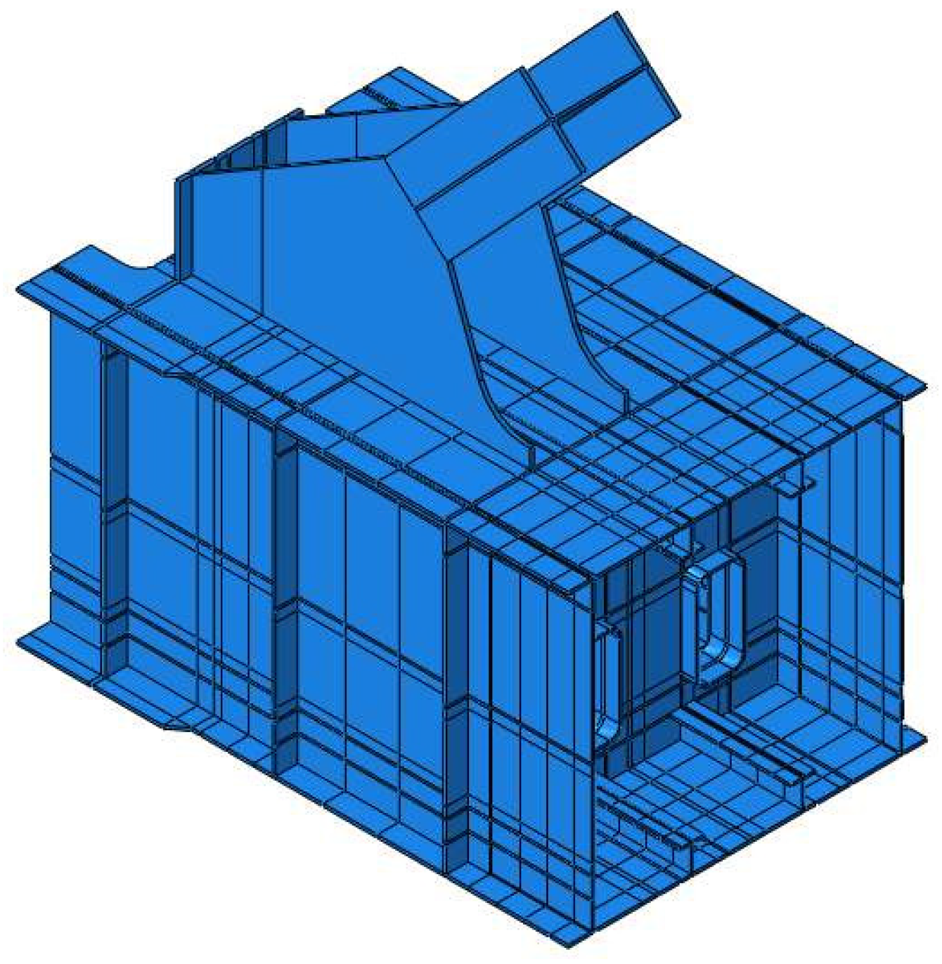
Taking the multiscale model of the support node as an example, the first step is to establish a solid element model for the support node. The geometric elements, such as the dimensions and thickness of the gusset plate, the size of transverse partitions, the openings in the transverse partitions, the longitudinal stiffening ribs on the node, and the T-shaped stiffening ribs on the upper and lower flanges of the gusset plate, are precisely modeled according to the design drawings. The accurate finite element model is illustrated in Figure 7.
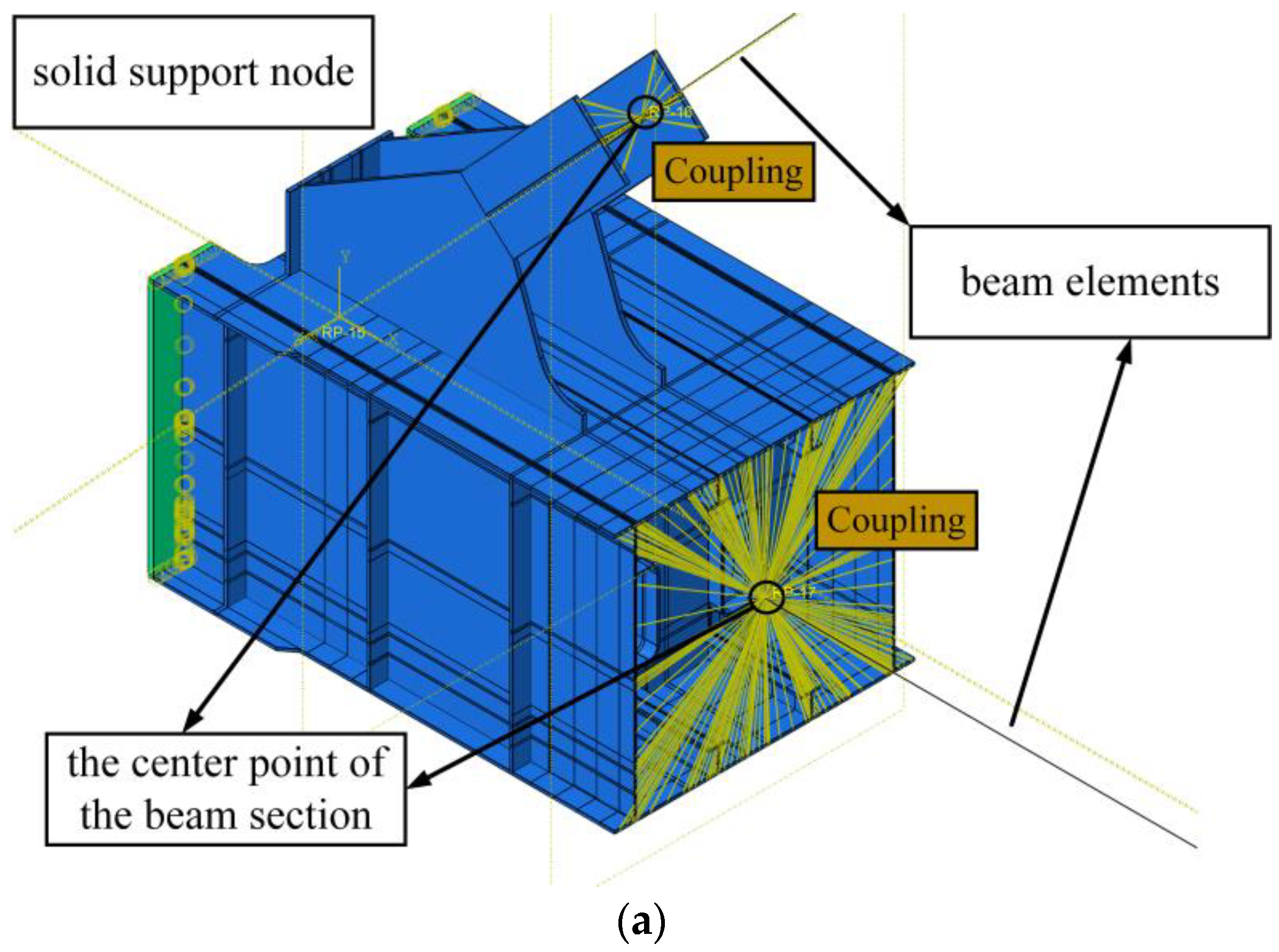
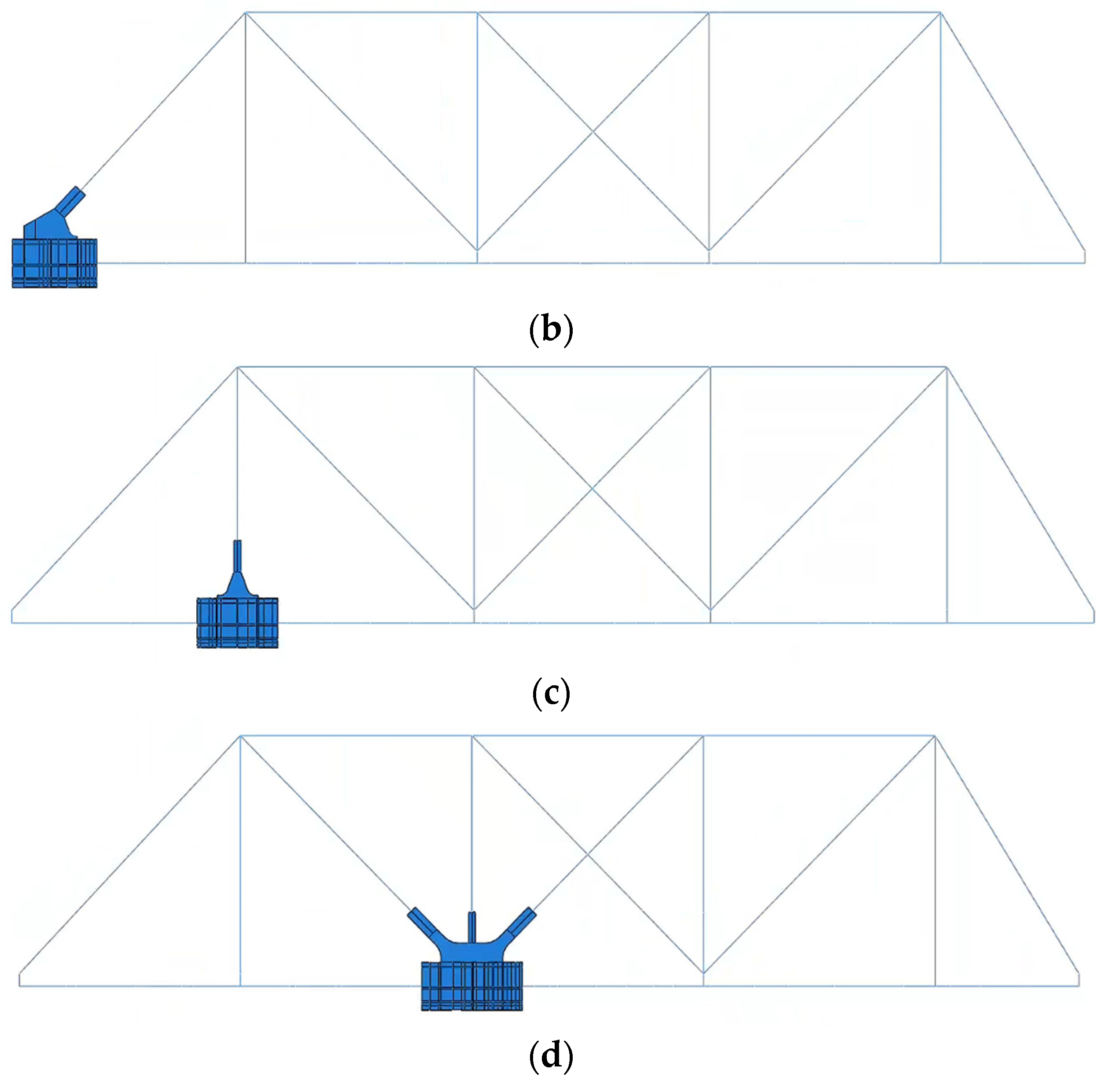
In actual engineering projects, the building structural material used is Q355C steel from China. For material properties, the density is set to 7850 kg/m3, the elastic modulus to 2.06 × 10¹¹ Pa, and the Poisson’s ratio to 0.3. The chosen element for the support node is the C3D8R solid element. For the overall bracket-crane truss, beam elements are used for modeling, except for the support nodes. The dimensions of the beam elements for different members will align with the settings in the frame model. To consider the eccentricity in the lower chord elements, rigid beams are introduced at the locations corresponding to the nodes of the lower chord beam elements, simulating the eccentricity of the lower chord’s box-shaped section. In the multiscale modeling procedure, it is crucial to appropriately couple elements of different dimensions at the interface point, in order to provide a uniform stress distribution and continuous displacement in the structural members. The applied dimensions of elements in the model must be appropriately coupled at the interface locations. Therefore, the coupling function in the interaction part of ABAQUS is introduced. The six degrees of freedom U1, U2, U3, UR1, UR2, and UR3 are constrained. At the connection points between nodes and beam elements, the cross-section of the solid support node is coupled to the center point of the beam section. Subsequently, the center point is coupled to the points connected to the beam element, establishing a multiscale model that includes both solid and beam elements, as shown in Figure 8a. The ABAQUS multiscale finite element model for the left support node of the bracket-crane truss is established, as illustrated in Figure 8b. The multiscale finite element models for the adjacent two nodes can be established in a similar manner, as shown in Figure 8c,d.

4.1.2. Comparison with the Frame Model Results

In structural design, performing complex finite element analyses is often impractical. Instead, simplified frame models are typically used for analysis. This paper aims to study the force transfer at critical weld locations of the lower chord node based on finite element results and to correlate these with the results from a frame model, thereby forming a design guide for the novel bracket-crane truss structure based on a simple frame model. Therefore, it is necessary to model the bracket-crane structure using a frame model and to compare the computational results of this frame model with those of the ABAQUS model.
The steel is treated as an elastic material with an elastic modulus of 206 GPa, Poisson’s ratio of 0.3, and a density of 7850 kg/m3. Beam elements are utilized to model various members of the bracket-crane truss.
The cross-sectional shapes of end web members, vertical braces, and upper chord members follow the information provided in Table 1. However, for the lower chord’s box-shaped section, adjustments are necessary due to the presence of T-shaped stiffening ribs on both upper and lower flanges. When using beam elements to model this section, the principle of the equivalent moment of inertia is applied. Specifically, Iz (the equivalent moment of inertia after adjustment) is calculated as the sum of I0 (the original moment of inertia before adjustment) and IT (the moment of inertia of the two T-shaped stiffening ribs). To facilitate this, the T-shaped ribs are converted to an equivalent 4 mm flange thickness. As a result, the beam element’s flange thickness for the box-shaped section in the frame model becomes 29 mm, while other dimensions remain consistent with the provided cross-sectional information. In the finite element modeling and analysis of the bracket-crane truss, despite employing different modeling methods, calculations are conducted on the same structure. The objective is to ensure minimal discrepancies in the results, thereby validating the chosen modeling methods. In this section, a comparative analysis is performed by applying identical load conditions to both the frame model structural model and the multiscale model of the left support node. Specifically, the load case with the maximum axial compression in the left end web member is focused on. The corresponding loads are then applied to each model, and the results from both the frame model and the multiscale finite element model are compared. This comparison demonstrates a high level of agreement between the results obtained using different modeling approaches.
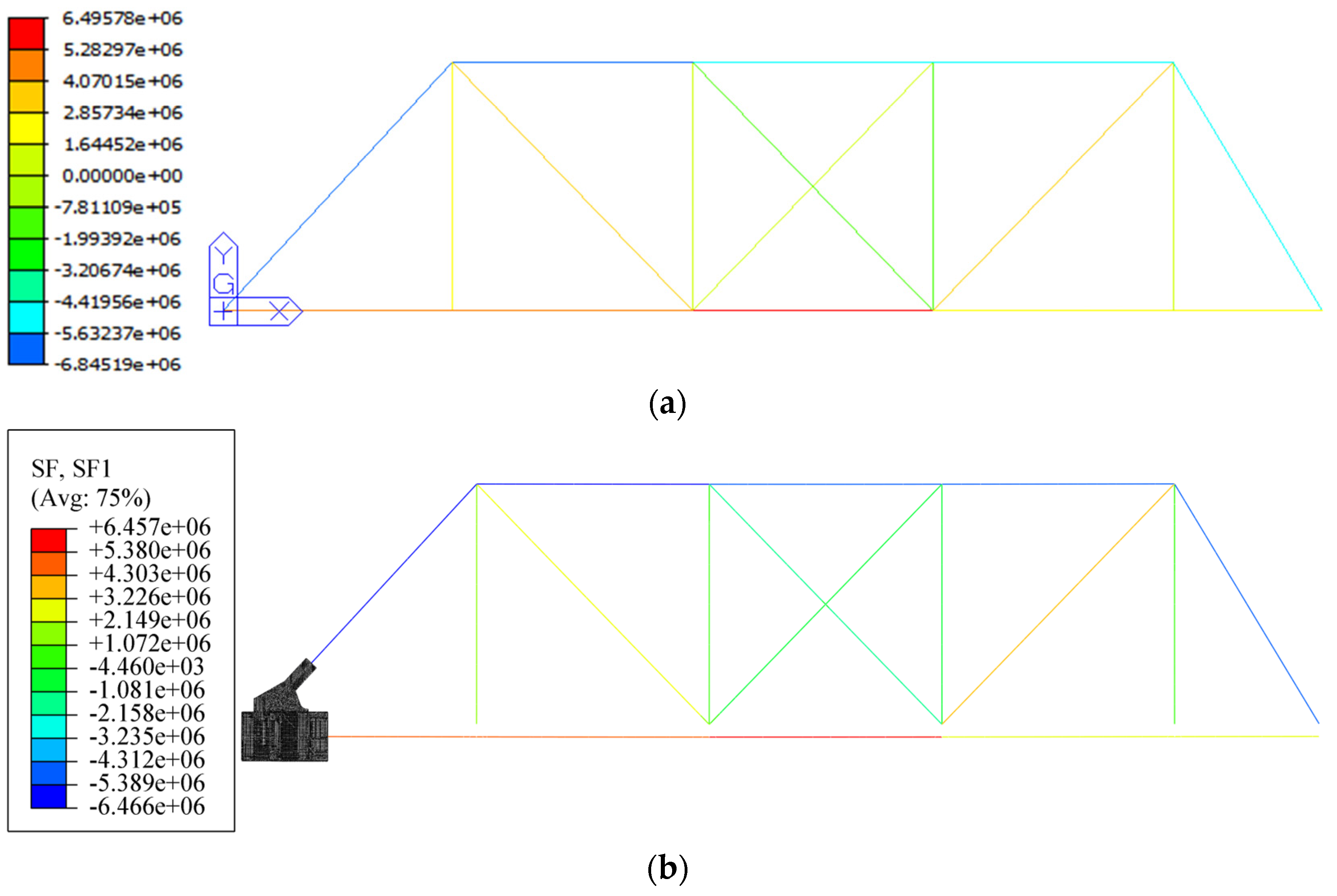
Under the same load condition, the axial force and displacement calculation results for the frame model are presented in Figure 9a and Figure 10a, respectively, while the corresponding results for the ABAQUS multiscale model are illustrated in Figure 9b and Figure 10b. The comparison reveals that, under identical load conditions, the axial force values for each member in both the frame model and the ABAQUS multiscale model exhibit close agreement. The axial force errors for each member indicate a high degree of consistency. Regarding displacement, the frame model predicts a maximum displacement of 37.6 mm for the bracket-crane truss structure, while the ABAQUS multiscale model indicates a maximum displacement of 34.7 mm. The displacement results from both models closely aligning. In summary, the axial force and displacement calculations from both models demonstrate strong agreement.

4.2. Analysis of the Load Transfer Mechanism at Lower Chord Nodes

For the welded integral node at the lower chord of the bracket-crane truss, it is essential to study the force transmission mechanism of the weld when subjected to loads. Since the frame model uses beam elements, the force transmission mechanism of the integral node weld seams cannot be directly analyzed from the frame model results. Therefore, it is necessary to propose the force transmission mechanism of the weld seams based on structural mechanics analysis. The proposed force transmission mechanism is then validated by incorporating finite element analysis results.

4.2.1. Node Construction

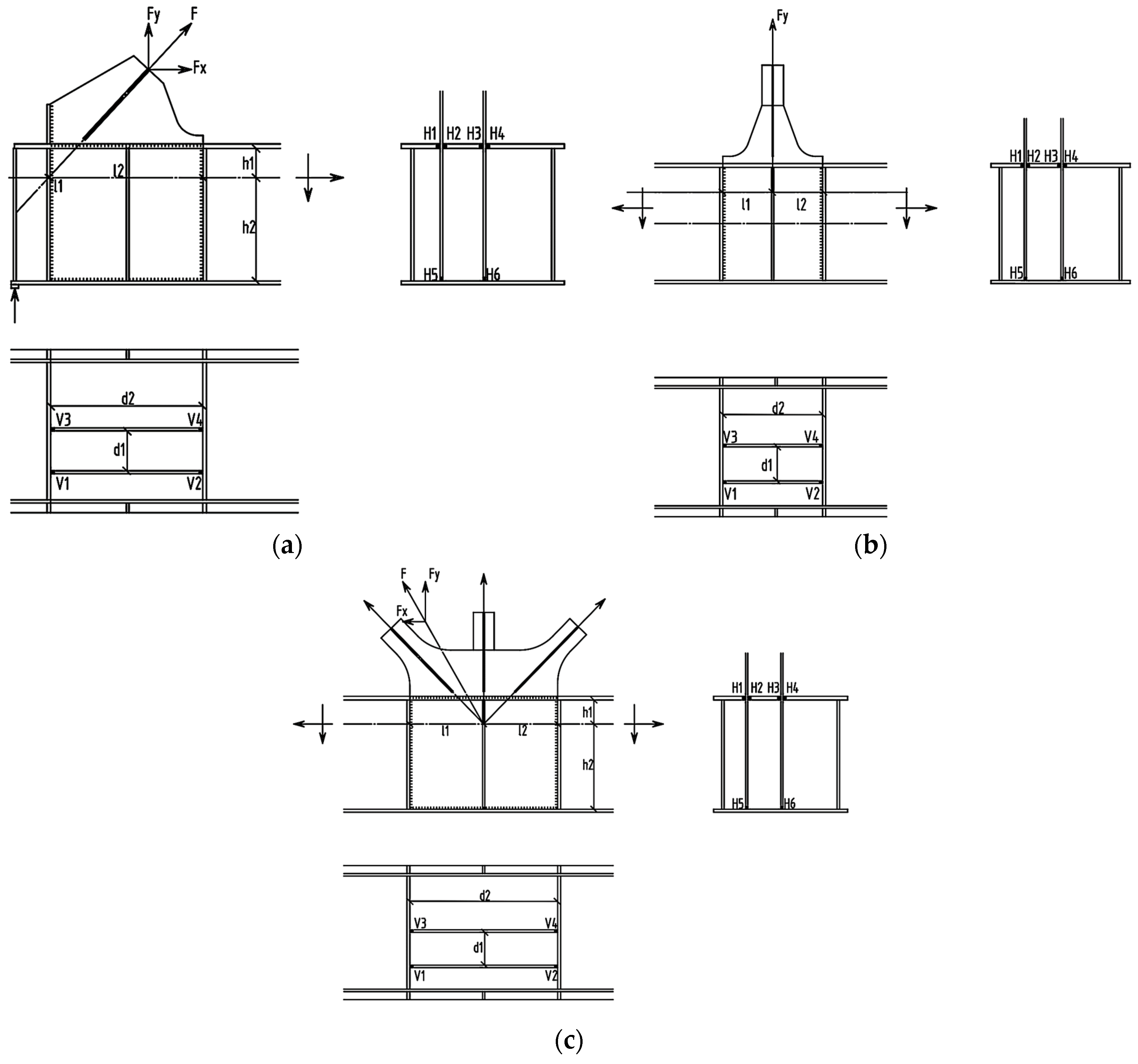
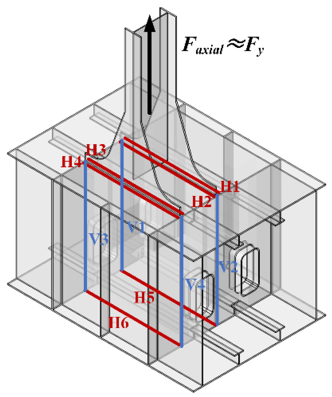
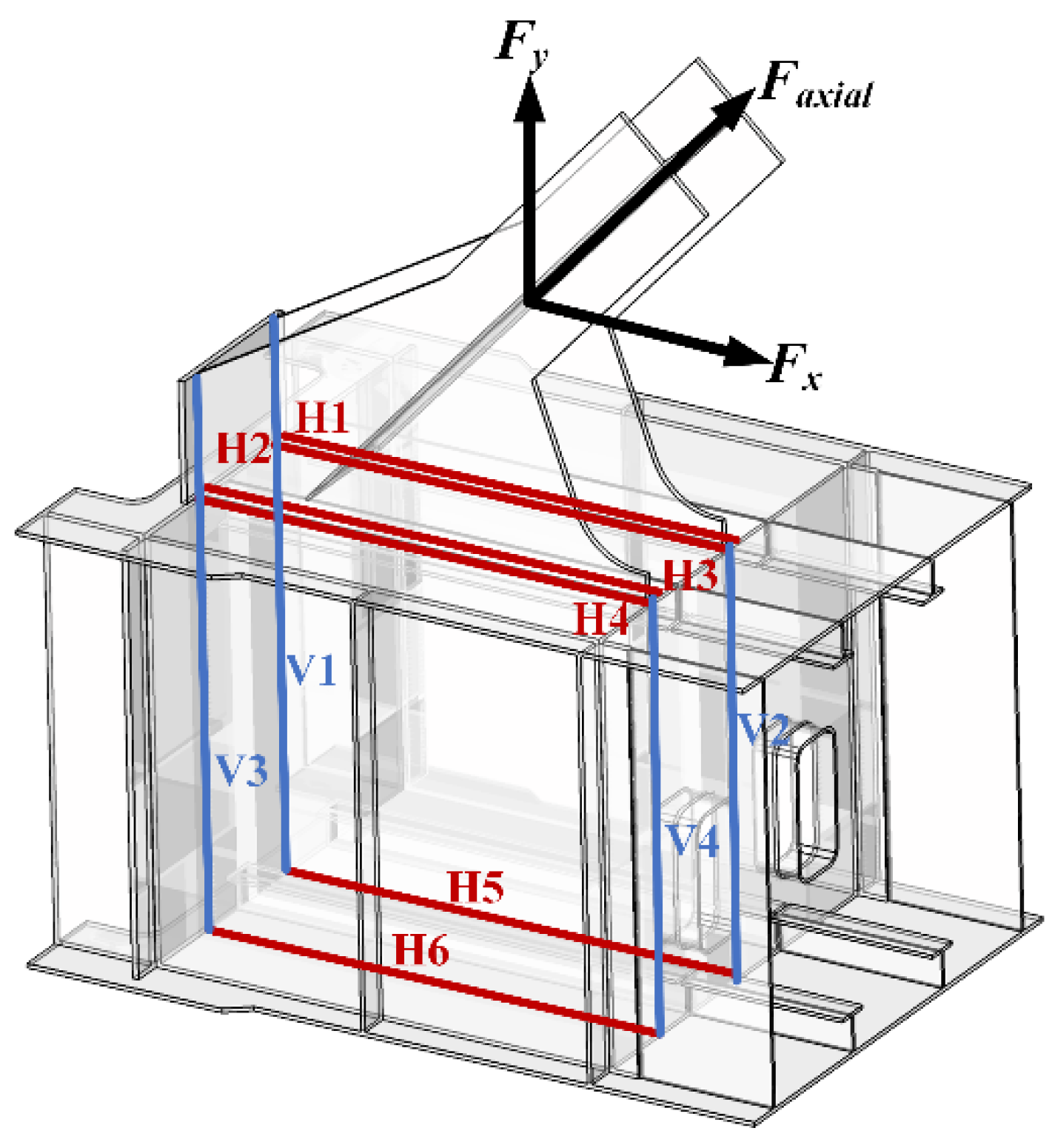
For the lower chord node, the upper flange of the lower chord member in the bracket-crane truss is slotted, and a gusset plate is inserted. The gusset plate is welded to the upper flange using a T-shaped weld, which is a combination of a butt weld and fillet weld. The connections between the lower flange and the lateral transverse diaphragm are welded using butt welds. Figure 11a–c annotates the positions of the connection welds between the gusset plate and the upper and lower flanges of the lower chord member, as well as the transverse diaphragm for the left support node, the node with only one web member, and the node with multiple web members in the bracket-crane truss.

4.2.2. Basic Assumptions

When the forces in the web member of the bracket-crane truss are transmitted to the lower chord node under the action of crane loads and roof loads, they are first transmitted through the gusset plate, then through the connection welds between the gusset plate and the upper and lower flanges, and the transverse diaphragm of the lower chord member. Finally, the forces are transmitted to the lower chord nodes and further to the supports on both sides of the bracket-crane truss. If the numerical values of the force transmission through the connection welds can be calculated using simplified formulas, it is possible to perform strength and fatigue checks on the welded joints using the formulas of materials mechanics. In the calculation of the force transmission formula, three basic assumptions are made:
Assumption 1.
The horizontal and vertical force components at the end of the web member follow specific paths of transmission: the horizontal force is transmitted through specific horizontal welds (H1, H2, H3, H4, H5, and H6), while the vertical force is transmitted through vertical welds (V1, V2, V3, and V4) within the lower chord box section. This takes into account the fact that the weld is mainly stressed in the length direction, and the stresses in the thickness direction are negligible.
Assumption 2.
The magnitude of the force transmitted by the welds is discussed concerning their distance from the center of the node. This emphasizes that the closer the welds are to the center of the node, the more force they share. According to the principle of torque equilibrium, the shorter the lever arm, the smaller the torque produced by the force on the structure. Therefore, the welding points closer to the center of the node have a shorter lever arm, which can more effectively resist torque.
Assumption 3.
Shear force, out-of-plane bending moments, and torsion at the end of the web member are neglected in the analysis. According to the frame model results, these influences are considered negligible for the force transmission through the connection welds of the integral node. When conducting structural analysis, to simplify calculations, the effects of some minor forces may be neglected. If the impact of these forces on the overall structural performance is negligible, they can be disregarded during the structural analysis phase.

4.2.3. Calculation Formulas for Weld Force Transfer in Nodes

For the bracket-crane truss, there are multiple members connected at the mid-span node of the lower chord. The derivation of the formulas will be introduced starting from the node with multiweb members of the lower chord.
(1)
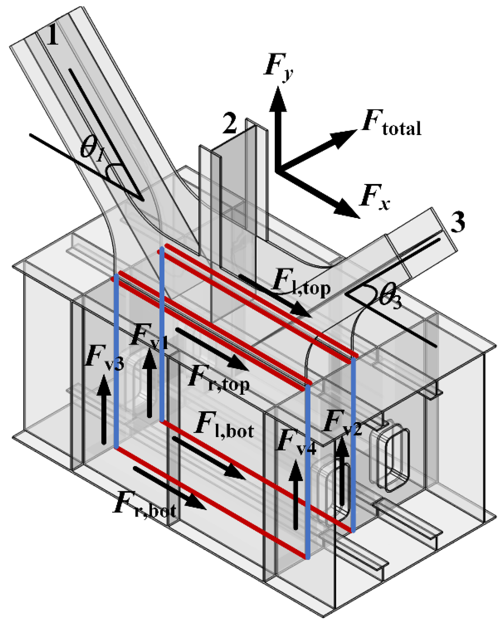
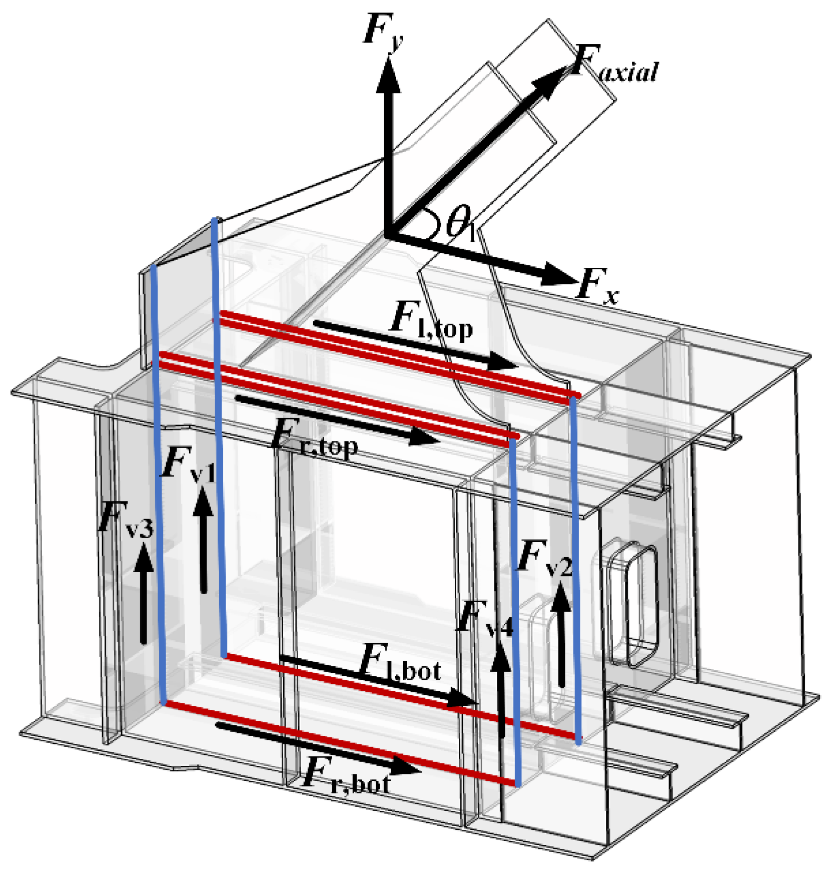
Node with multiweb members: Figure 12 illustrates the force transmission paths of the transverse welds and vertical welds connecting the gusset plate at the node with multiweb members.
For the horizontal welds, the distribution coefficients for the upper and lower sides are
ε t = h 2 h 1 + h 2
ε b = h 1 h 1 + h 2
where ε t is the distribution ratio of the horizontal force transmitted by the upper flange, ε b is the distribution ratio of the horizontal force transmitted by the lower flange, h 1 is the distance from the horizontal axis to the upper flange as annotated in Figure 12, and h 2 is the distance from the horizontal axis to the lower flange as annotated in Figure 12.
The horizontal component of the axial force of the web member transmitted through the weld is
F l , top = F r , top = ε t ( F n 1 cos θ 1 + F n 3 cos θ 3 2 ) = ε t F x 2
F l , bot = F r , bot = ε b ( F n 1 cos θ 1 + F n 3 cos θ 3 2 ) = ε b F x 2
where F l , top is the sum of the forces transmitted by H1 and H2 as annotated in Figure 12, F r , top is the sum of the forces transmitted by H3 and H4 as annotated in Figure 12, F l , bot is the force transmitted by H5 as annotated in Figure 12, F r , bot is the force transmitted by H6 as annotated in Figure 12, F x is the horizontal component of the resultant force as annotated in Figure 12, and θ 1 and θ 3 is the angle between the web member and the horizontal line as annotated in Figure 12.
The force transmitted by the weld due to the in-plane bending moment at the end face of the web member is
F l , top = ε t ( M y 1 cos θ 1 + M y 3 cos θ 3 d 1 )
F l , bot = ε b ( M y 1 cos θ 1 + M y 3 cos θ 3 d 1 )
F r , top = ε t ( M y 1 cos θ 1 + M y 3 cos θ 3 d 1 )
F r , bot = ε b ( M y 1 cos θ 1 + M y 3 cos θ 3 d 1 )
where M y 1 is the in-plane bending moment of web member 1, M y 3 is the in-plane bending moment of web member 3, and d1 is the distance between two gusset plates as shown in Figure 11.
By summing up the values and considering safety factors k h , the formula for the force transmitted by the weld is obtained:
F l , top = k h ε t ( F x 2 + M y 1 cos θ 1 + M y 3 cos θ 3 d 1 )
F l , bot = k h ε b ( F x 2 + M y 1 cos θ 1 + M y 3 cos θ 3 d 1 )
F r , top = k h ε t ( F x 2 M y 1 cos θ 1 + M y 3 cos θ 3 d 1 )
F r , bot = k h ε b ( F x 2 M y 1 cos θ 1 + M y 3 cos θ 3 d 1 )
where k h is the safety factor for the horizontal weld force transmission.
Considering the most unfavorable situation, i.e., the horizontal weld with the maximum transmitted force, the numerical value of the transmitted force is
F h , max = k h ε max ( | F x 2 | + | M y 1 cos θ 1 + M y 3 cos θ 3 d 1 | )
where F h , max is the maximum value of the horizontal weld force transmission, and ε max is the larger value between the distribution coefficients ε t and ε b .
For the vertical welds: the distribution coefficients for the left and right vertical welds are
η 1 = l 2 l 1 + l 2
η r = l 1 l 1 + l 2
where η 1 is the distribution ratio of the vertical force transmitted by the left vertical weld, η r is the distribution ratio of the vertical force transmitted by the right vertical weld, l 1 is the distance from the left transverse plate to the vertical axis as annotated in Figure 12, and l 2 is the distance from the right transverse plate to the vertical axis as annotated in Figure 12.
The force transmitted through the weld by the vertical component is
F v 1 = F v 2 = η 1 ( F n 1 sin θ 1 + F n 2 + F n 3 sin θ 3 2 ) = η 1 F y 2
F v 3 = F v 4 = η r ( F n 1 sin θ 1 + F n 2 + F n 3 sin θ 3 2 ) = η r F y 2
where F vi is the vertical component of the force in the weld Vi as annotated in Figure 12, and F y is the vertical component of the resultant force as annotated in Figure 12.
The force transmitted by the weld due to the in-plane bending moment at the end face of the web member is
F v 1 = η 1 ( M y 1 sin θ 1 + M y 2 + M y 3 sin θ 3 d 1 )
F v 2 = η 1 ( M y 1 sin θ 1 + M y 2 + M y 3 sin θ 3 d 1 )
F v 3 = η r ( M y 1 sin θ 1 + M y 2 + M y 3 sin θ 3 d 1 )
F v 4 = η r ( M y 1 sin θ 1 + M y 2 + M y 3 sin θ 3 d 1 )
By summing up the values and considering the nonuniformity coefficient of internal forces k v , the formula for the force transmission of the vertical weld is derived:
F v 1 = k v η 1 ( F y 2 + M y 1 sin θ 1 + M y 2 + M y 3 sin θ 3 d 1 )
F v 2 = k v η 1 ( F y 2 M y 1 sin θ 1 + M y 2 + M y 3 sin θ 3 d 1 )
F v 3 = k v η r ( F y 2 + M y 1 sin θ 1 + M y 2 + M y 3 sin θ 3 d 1 )
F v 4 = k v η r ( F y 2 M y 1 sin θ 1 + M y 2 + M y 3 sin θ 3 d 1 )
where k v is the nonuniformity coefficient for the force transmission of the vertical weld.
Considering the most unfavorable situation, i.e., the vertical weld with the maximum transmitted force, the numerical value of the transmitted force is
F v , max = k v η max ( | F y 2 | + | M y 1 sin θ 1 + M y 2 + M y 3 sin θ 3 d 1 | )
where F v , m is the maximum value of the force transmission for the vertical weld, and η max is the larger value between the distribution coefficients η r and η 1 .
(2)
Node with only one vertical web member: Figure 13 illustrates the force transmission paths of the node with only one vertical web member.
The nodes adjacent to the support are only connected to a vertical brace, making the node structure simpler. Based on the same assumptions, the shear force at the end of the web member connected to the node is negligible, resulting in a small numerical value for the horizontal weld force and high safety. Therefore, the horizontal weld force transmission for the nodes adjacent to the lower chord support is not considered. The formula for vertical weld force can be derived:
F v 1 = k v η 1 ( F y 2 + M y 1 d 1 )
F v 2 = k v η 1 ( F y 2 M y 1 d 1 )
F v 3 = k v η r ( F y 2 + M y 1 d 1 )
F v 4 = k v η r ( F y 2 M y 1 d 1 )
Considering the most unfavorable situation, i.e., the vertical weld with the maximum transmitted force, the numerical value of the transmitted force is
F v , m = k v η m ( | F y 2 | + | M y 1 d 1 | )
(3)
Lower chord support nodes: Figure 14 illustrates the force transmission paths of the lower chord support nodes:
The support node is connected to a web member, and the axial force in the web member can be decomposed into two components: horizontal and vertical. Therefore, similar to the mid-span nodes, both the force transmitted through the horizontal weld and the force transmitted through the vertical weld need to be considered. Using a similar derivation approach as before, the formula for force transmission through the horizontal weld is derived:
F l , top = k h ε t ( F x 2 + M y 1 cos θ 1 d 1 )
F l , bot = k h ε b ( F x 2 + M y 1 cos θ 1 d 1 )
F r , top = k h ε t ( F x 2 M y 1 cos θ 1 d 1 )
F r , bot = k h ε b ( F x 2 M y 1 cos θ 1 d 1 )
Considering the most unfavorable situation, i.e., the horizontal weld with the maximum transmitted force, the numerical value of the transmitted force is
F h , m = k h ε m ( | F x 2 | + | M y 1 cos θ 1 d 1 | )
The formula for force transmission through the vertical weld is
F v 1 = k v η 1 ( F y 2 + M y 1 sin θ 1 d 1 )
F v 2 = k v η 1 ( F y 2 M y 1 sin θ 1 d 1 )
F v 3 = k v η r ( F y 2 + M y 1 sin θ 1 d 1 )
F v 4 = k v η r ( F y 2 M y 1 sin θ 1 d 1 )
Considering the most unfavorable situation, i.e., the vertical weld with the maximum transmitted force, the numerical value of the transmitted force is
F v , max = k v η max ( | F y 2 | + | M y 1 sin θ 1 d 1 | )
In summary, for the three types of node constructions, when the inclined strut is connected to the lower chord node of the bracket-crane truss, the maximum value of the lateral force transmitted through the transverse weld is. For the support node, the uneven distribution coefficient is larger, set to 1.6; for other nodes, it is set to 1.
F h , max = k h ε max ( | F x 2 | + | M y i cos θ i d 1 | )
The maximum value of the vertical force transmitted by the vertical fillet weld is obtained, as expressed in Formula (43). For support nodes, take it as 1; for other nodes, take it as 1.3.
F v , max = k v η max ( | F y 2 | + | M y i sin θ i d 1 | )

5. Discussion

To validate the rationality of the force transmission formula for the bracket-crane truss, static load conditions outlined in Section 4.1.1 are selected for verification. These conditions involve the presence of two cranes on both sides, considering factors such as self-weight, roof dead load, roof live load, and crane wheel loads. As the cranes assume different positions, the force distribution within the bracket-crane truss experiences variations. Ensuring the broad applicability and safety of the proposed formulas necessitates validation under diverse loading conditions. Therefore, representative load cases, covering different positions of crane loading from left to right, are chosen.
To account for the impact of crane loads at various positions on the overall bracket-crane truss, specific load cases are selected for different nodes. For the lower chord support node, 5 load cases (R2, R3, R6, R13, and R20) are considered for the right span and 5 load cases (L2, L3, L6, L13, and L17) for the left span, resulting in a total of 25 load cases for formula verification. The node near the lower chord support has 5 load cases (R1, R7, R10, R14, and R15) for the right span and 5 load cases (L4, L10, L11, L14, and L16) for the left span, totaling 25 load cases. The mid-span node is represented by 5 load cases (R10, R14, R17, R19, R20) for the right span and 5 load cases (L1, L5, L10, L11, L15) for the left span, resulting in a total of 25 load cases for formula verification.

5.1. Validation of Force Transmission Paths

To validate Assumption 1 made during the theoretical derivation, the horizontal component (Fx) and vertical component (Fy) of the resultant force in the web member are assessed, assuming that these forces are carried by the horizontal and vertical welds, respectively. In this validation process, the horizontal forces were extracted from the element sets corresponding to the different load cases of the horizontal welds, and the vertical forces were extracted from the element sets corresponding to the different load cases of the vertical welds. Subsequently, a detailed comparison was conducted between these forces and the horizontal and vertical components of the resultant force in the web member.
1.
Node with multiweb members
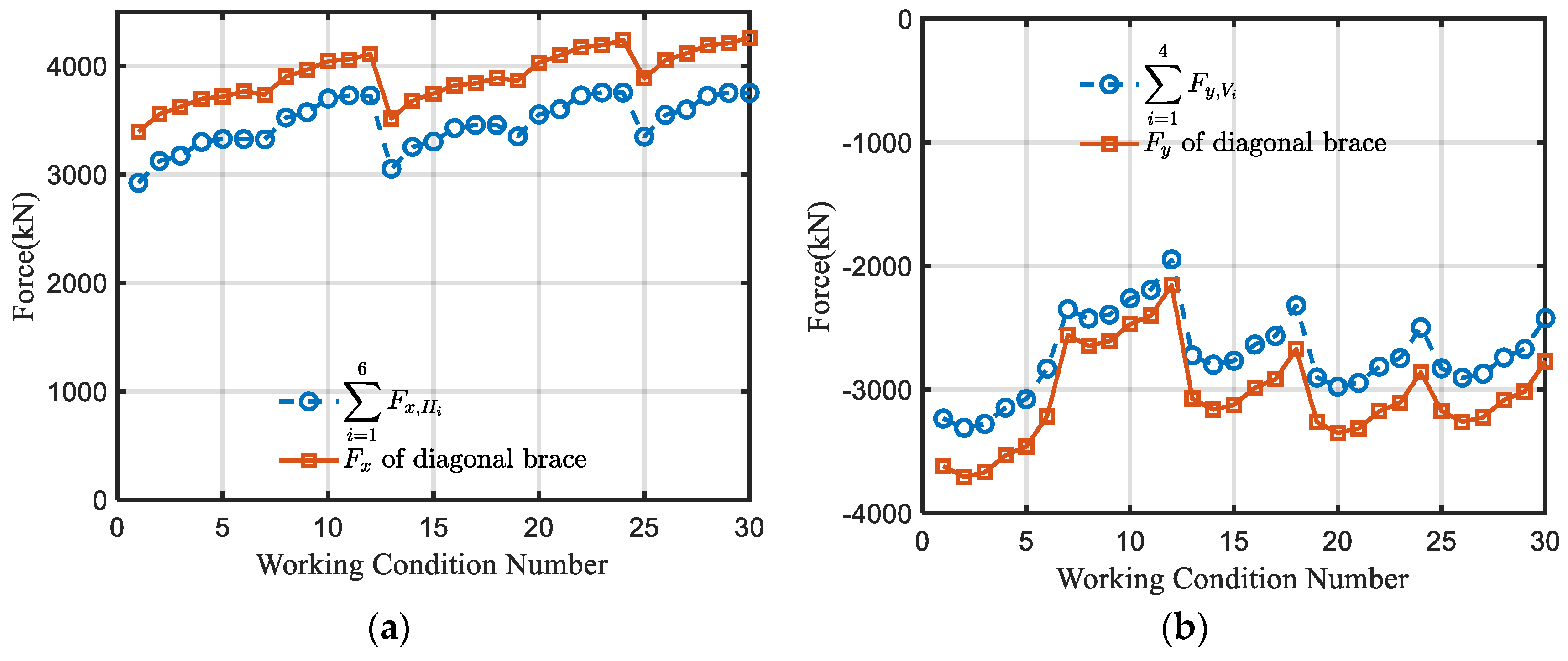
For the node with multiweb members and the 25 load cases mentioned above, the sum of the horizontal forces of the welds (consisting of H1 to H6) and the sum of the vertical forces of the welds (consisting of V1 to V4) was calculated. These two sums were then compared with the horizontal component (Fx) and the vertical component (Fy) of the axial force in the web member, as illustrated in Figure 15.
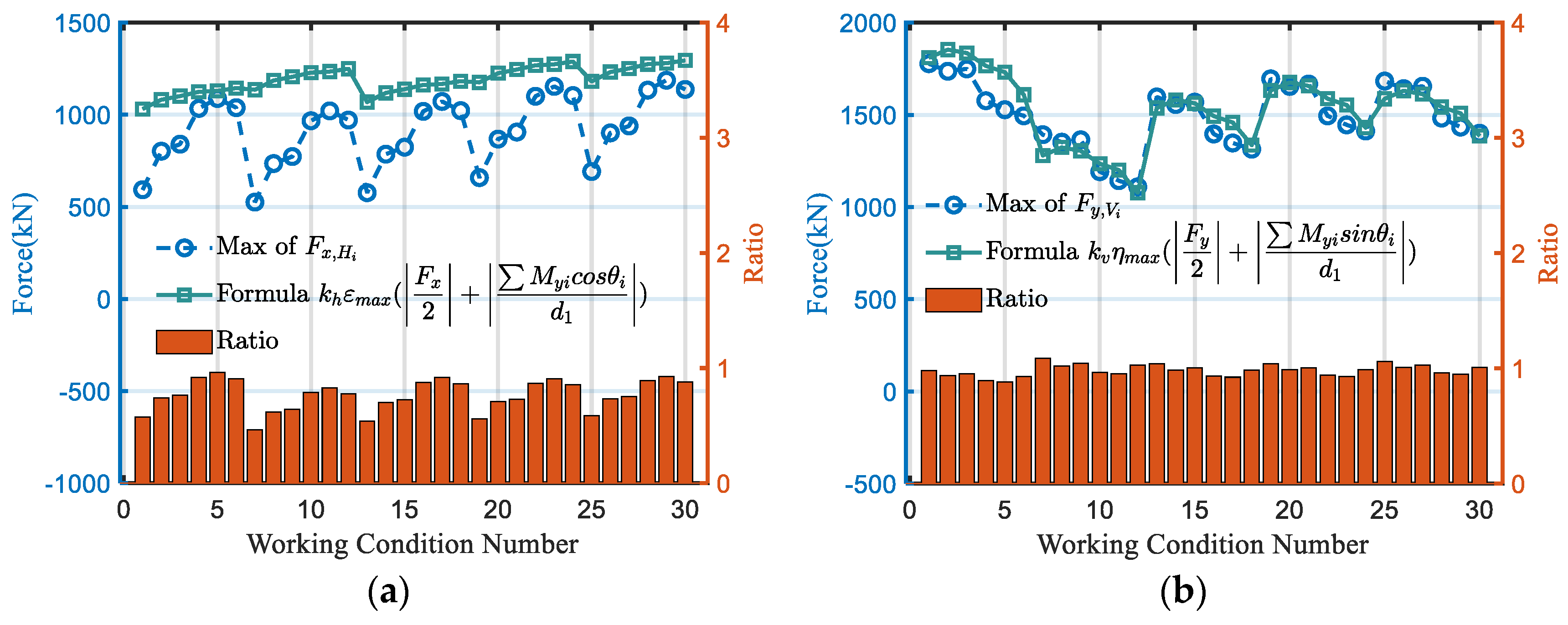
The data comparison results for horizontal and vertical weld force transmissions are depicted in Figure 16. The findings affirm the validity of the previously hypothesized Assumption 1. Specifically, the horizontal welds effectively transmit the horizontal component of the web member, and the vertical weld reliably transmits the vertical component of the web member. This confirmation underscores the accuracy of Assumption 1. Additionally, it is noteworthy that the magnitude of the resultant force of the weld is observed to be less than the magnitude of the corresponding component force of the web rod. Consequently, adopting a conservative approach by equating the resultant force of the weld with the component force of the web rod is deemed acceptable for the project.
2.
Node with only one web member
For the node with only one web member and the 25 load cases mentioned previously, the sum of the horizontal forces of welds (consisting of H1 to H6) and the sum of the vertical forces of welds (consisting of V1 to V4) was calculated. These two sums were then compared with the horizontal component (Fx) and the vertical component (Fy) of the axial force in the web member, as illustrated in Figure 17.
The data comparison results for horizontal and vertical weld force transmissions are illustrated in Figure 18. Both horizontal and vertical force transmissions align well with the previously hypothesized Assumption 1. As stated in Assumption 3, shear force is neglected for the web member, and since it only has vertical brace members, the horizontal force transmission through the weld at this location is negligible and can be disregarded. Therefore, the force transmission at this type of node is solely considered for the vertical force. The vertical weld reliably transmits the vertical component of the web member, confirming the accuracy of Assumption 1.
3.
Left Support Node
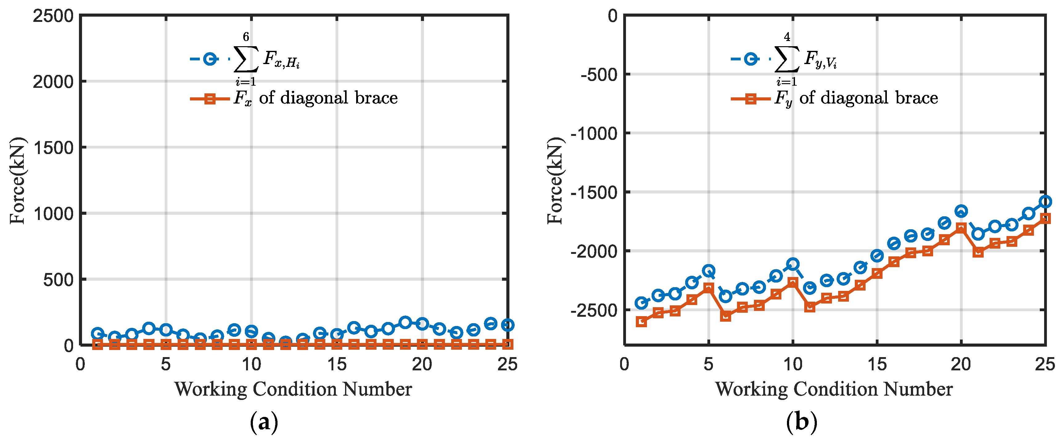
For the left support node and the 25 load cases previously mentioned, the sum of the horizontal forces of welds (consisting of H1 to H6) and the sum of the vertical forces of welds (consisting of V1 to V4) was calculated. These two sums were then compared with the horizontal component (Fx) and the vertical component (Fy) of the axial force in the end web member, as illustrated in Figure 19.
The data comparison results for horizontal and vertical weld force transmissions are presented in Figure 20. It is evident that both horizontal and vertical force transmissions align well with the previously hypothesized Assumption 1. The horizontal welds effectively transmit the horizontal component of the web member, while the vertical welds reliably transmit the vertical component of the web member, confirming the accuracy of Assumption 1.

5.2. Verification of Simplified Transmission Calculation Formulas

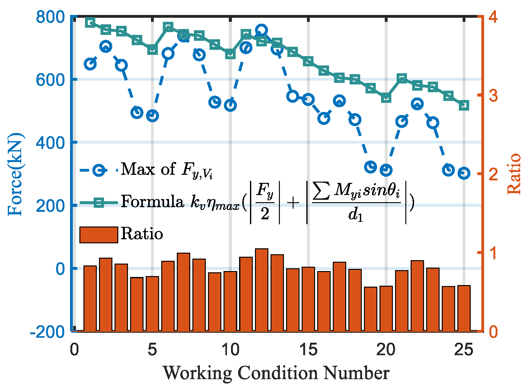
Figure 21, Figure 22 and Figure 23 present not only the maximum value of the nominal force extracted from ABAQUS 2022 software and the corresponding formula result but also provide the ratio of the formula result and the extracted result. Figure 21 and Figure 22 offer a comparison of both horizontal and vertical forces, while Figure 23 focuses solely on the vertical force, given that the horizontal force of the node with only one web member can be considered negligible. A close examination of these figures reveals that the calculated results from the proposed simplified formula align closely with the finite element results. Moreover, the formula effectively captures the changing trend of stress on the weld, demonstrating its ability to provide useful estimations.
For the node with only one web member, it is evident that the error is relatively larger. However, this discrepancy is attributed to the smaller magnitude of the vertical weld force in the node with only one web member when compared with the vertical welds of other nodes. The force transmission of the vertical welds in the node with only one web member is below 1000 kN, while the vertical welds of other nodes exceed 1000 kN, reaching up to 3000 kN. Therefore, despite the larger error, the calculated results from the formula consistently exceed the extracted results of the weld force. This conservative approach is deemed acceptable for the project.
The comparison of the horizontal force transmission between the left support node and the node with multiweb members reveals a gradual increase in error as the considered node moves away from the support. This behavior can be attributed to the fixed end of the support node, resulting in a clearer force distribution. In contrast, the mid-span node, situated in space, experiences more complex forces influenced by the length of the crane itself. At the same time, nodes with fewer bars are subject to more straightforward forces, such as the support node and nodes with only one vertical web member, where the calculation formulas tend to be relatively accurate with smaller errors. However, in nodes with more web members, there is an interplay of internal forces between the members, with complex mechanisms of cancellation or superposition, which can lead to a certain degree of reduced accuracy in the calculation formulas. Consequently, accurately describing their force transmission mode with a simple formula becomes challenging, necessitating a comprehensive consideration of multiple factors. Despite these complexities, the current simplified formula yields calculation results larger than the extracted results, highlighting the conservative approach is suitable for assisting in structural design.
When verifying the crane truss structure, it is necessary to conduct verifications in three aspects: strength, stability, and fatigue. For steel structures that bear dynamic loads over the long term, particular attention must be paid to the fatigue issues of the welded joints, as these can greatly affect the long-term service life of the structure. Current codes use the nominal stress at the weld location and the S-N curve of the construction details for comparison to predict the fatigue life of the structure. For welds in complex geometric positions, the nominal force they bear needs to be obtained through the establishment of a solid model, which poses a certain degree of difficulty for engineers. The method proposed in this paper only uses the simulation results of the frame model (which can be calculated by a large number of commercial software) combined with the force transmission method and the simplified formulas proposed in this paper to calculate the nominal force of the welds at critical positions. The calculation results are conservative, which greatly reduces the difficulty of the verification of the bracket-crane truss structure and has strong operability in engineering.

6. Future Work

In the realm of engineering project design, addressing the intricacies of crane truss structures and enhancing the application of fatigue analysis methods can be achieved through the following strategic approaches.
Nominal Force at the Weld Location: By theoretical analysis and derivation, a calculation method from the internal forces of the members to the nominal force at the weld location is established, laying the foundation for the practical application of structural fatigue analysis. Developing a simplified method to accurately calculate the nominal stress at potential hazardous welding locations in fully welded joints for structural verification involves several key issues that need to be addressed. The welding areas are often regions of stress concentration, which are common causes of structural failure. Accurately predicting the stress concentration factors in these areas is a challenge. Understanding how loads are transferred through the welded joints is crucial. Simplified methods must accurately represent the load paths and how they are affected by the welding geometry. Any simplified method requires verification and validation through experimental data or more complex numerical simulations to ensure its accuracy and reliability.
Structural Decomposition and Classification: Breaking down complex structural forms to classify construction details at critical junctures. By comparing these classifications with established S-N curves, it becomes feasible to forecast the fatigue life of the structure.
Innovative Detail Analysis: During the decomposition process, one may encounter construction details that are not encompassed by existing specifications. For these novel details, conducting dedicated fatigue tests will help accumulate essential data, thereby offering empirical and theoretical backing for future standards development. The fatigue life of structures with complex geometries poses multifaceted problems. On one hand, due to the complex geometries, existing specifications often do not cover the corresponding classifications, making it difficult to predict fatigue life through current standards. On the other hand, complex geometries can also subject critical locations to multiaxial stress states, significantly reducing the structure’s fatigue life. Starting from these two points, to address the life prediction issue for structures with complex geometries, one should combine finite element simulation technology to focus on developing solution methods for local stress states, finding a balanced scale between macroscopic stress states and local stress states that can to some extent free itself from the influence of external geometric dimensions. On the other hand, predictive methods for fatigue life under multiaxial stress states should be developed to refine the prediction of structural fatigue life.
Advanced Simulation and Theoretical Prediction: Harnessing finite element simulation technology to precisely model the stress distribution at weld locations. Employing sophisticated theories can facilitate the prediction of the fatigue life for complex nodes, potentially eliminating the need for physical testing. The continuous progress of finite element software plays a vital role in advancing new stress analysis techniques for welded structures, which can be attributed to several aspects. It can accurately obtain the stress distribution at locations such as weld toes or other areas of stress concentration. Utilizing these local stress states for fatigue analysis can eliminate the influence of macroscopic shapes. Modern finite element software is capable of analyzing the coupling of multiple physical fields (e.g., thermo–mechanical coupling, fluid–structure interaction), which is particularly important for understanding the heat-affected zone and residual stresses during the welding process. Utilizing virtual testing technology, based on established theories, the fatigue life of new construction details can be predicted, reducing the sole dependence on experimental methods.
Multiaxial Fatigue Life Prediction: Given that structures are subjected to spatial forces in actual service, the development of multiaxial fatigue life prediction methodologies will enable a more precise estimation of the structure’s fatigue life under real-world conditions.
At present, only numerical simulation methods have been employed, with refined modeling of the overall nodes, to analyze the force characteristics and transmission paths of this new type of bracket-crane truss structure and to provide a calculation method for the nominal forces of welds at critical positions. However, simulations alone cannot determine the credibility of the results. Therefore, subsequent work will involve collecting on-site data through the use of strain gauges on an actual bracket-crane truss structure to verify the accuracy of the model and to establish a load spectrum generated by crane loads using experimental data. At the same time, corresponding experimental studies will be conducted on the prominent issues faced by the bracket-crane truss structure—fatigue issues. For instance, scaled tests on welded overall nodes and high-cycle fatigue tests on critical construction details that are not covered by current codes, which appear in this new type of structure, will be carried out. Additionally, since the bracket-crane truss structure is under spatial force conditions, a uniaxial fatigue verification is not sufficiently safe and scientific. Multiaxial fatigue tests and research on related theoretical methods will be conducted to provide solutions for fatigue issues in bracket-crane truss structures and similar steel building structures.

7. Conclusions

This paper addresses the design challenges of the innovative bracket-crane truss structure by proposing a simplified nominal force calculation formula for critical weld locations of the integrated node. Based on the simulation studies and formula deduction, the main conclusions drawn are as follows:
(1)
The study establishes a frame model and ABAQUS multiscale models, utilizing engineering project drawings and data, verifying the similarities between the two simulation methods, providing a theoretical basis for designing using a frame model.
(2)
The derivation of force transmission formulas for various welds in the lower chord nodes of the bracket-crane truss, from a structural mechanics standpoint based on appropriate assumptions, establishes a connection between the internal forces of interconnected chord members and the force transmission values of the welds.
(3)
The investigation of three types of lower chord nodes in the bracket-crane truss, using a multiscale finite element model under diverse conditions, affirms the force transmission patterns in the lower chord nodes. Specifically, horizontal welds transmit horizontal forces, while vertical welds transmit the entire vertical force.
(4)
Validation of the derived formulas for weld force transmission under various load conditions was conducted through a comparative analysis between the multiscale ABAQUS model and the simplified formula results. It is proved that the accuracy of the proposed formula can be applied in engineering.

Author Contributions

Conceptualization, H.Z. and W.Z.; methodology, S.L.; software, S.L.; validation, S.L., L.T. and J.F.; formal analysis, S.L.; investigation, S.L.; resources, H.Z., C.D. and Z.G.; data curation, S.L.; writing—original draft preparation, S.L.; writing—review and editing, S.L., W.Z. and L.T.; visualization, S.L. and L.T.; supervision, W.Z.; project administration, H.Z. and W.Z.; funding acquisition, H.Z., Z.G. and C.D. All authors have read and agreed to the published version of the manuscript.

Funding

This research was funded by [the National Natural Science Foundation of China] grant number [51978206] and by [Capital Engineering & Research Incorporation Limited] grant number [KB22022-A-016-204351-0]. The APC was funded by [the National Natural Science Foundation of China] grant number [51978206].

Data Availability Statement

The raw data supporting the conclusions of this article will be made available by the authors on request.

Conflicts of Interest

Authors He Zhao, Zhongyan Guo, Chao Dong and Jiangtao Fan are employed by the Capital Engineering & Research Incorporation Limited. The remaining authors declare that the research was conducted in the absence of any commercial or financial relationships that could be construed as a potential conflict of interest.

Nomenclature

ε t the distribution ratio of the horizontal force transmitted by the upper flange
ε b the distribution ratio of the horizontal force transmitted by the lower flange
h 1 the distance from the horizontal axis to the upper flange
h 2 the distance from the horizontal axis to the lower flange
F l , top the sum of the forces transmitted by H1 and H2 as annotated in Figure 12
F l , bot the force transmitted by H5 as annotated in Figure 12
F r , bot the force transmitted by H6 as annotated in Figure 12
F x the horizontal component of the resultant force as annotated in Figure 12
θ 1 , θ 3 the angle between the web member and the horizontal line as annotated in Figure 12.
M y 1 the in-plane bending moment of web member 1
M y 3 the in-plane bending moment of web member 3
d1the distance between two gusset plates as shown in Figure 11
k h the safety factor for the horizontal weld force transmission
F h , max the maximum value of the horizontal weld force transmission
ε max the larger value between the distribution coefficients ε t and ε b .
η 1 the distribution ratio of the vertical force transmitted by the left vertical weld
η r the distribution ratio of the vertical force transmitted by the right vertical weld
l 1 the distance from the left transverse plate to the vertical axis as annotated in Figure 12
l 2 the distance from the right transverse plate to the vertical axis as annotated in Figure 12
F vi the vertical component of the force in the weld Vi as annotated in Figure 12
F y the vertical component of the resultant force as annotated in Figure 12.
k v the nonuniformity coefficient of internal forces
F v , m maximum value of the force transmission for the vertical weld
η max the larger value between the distribution coefficients η r and η 1 .

References

  1. Eremin, K.I.; Shulga, S.N. Modelirovanie razvitiya ustalostnykh povrezhdeniy v podkranovo-podstropil’nykh fermakh. Proc. Mosc. State Univ. Civ. Eng. 2014, 2, 30–38. (In Russian) [Google Scholar]
  2. Nikitina, E.A.; Khazov, P.A.; Brickel, D.M. Determination of residual life of crane truss taking into account damage accumulation in real operating conditions. Volga Reg. Sci. J. 2018, 1, 9–14. (In Russian) [Google Scholar]
  3. Tusnina, O.A. Finite element analysis of crane secondary truss. Mag. Civ. Eng. 2018, 1, 68–89. [Google Scholar]
  4. Euler, M.; Taylor, C. Fatigue action on crane runway beams. J. Constr. Steel Res. 2021, 181, 106476. [Google Scholar] [CrossRef]
  5. Euler, M.; Kuhlmann, U. Crane runways—Fatigue evaluation of crane rail welds using local concepts. Int. J. Fatigue 2011, 33, 1118–1126. [Google Scholar] [CrossRef]
  6. Zai, J.; Cao, J.; Bell, A.J. The fatigue strength of box girders in overhead travelling cranes. Int. J. Fatigue 1996, 72, 401–405. [Google Scholar] [CrossRef]
  7. Shulga, S.N. Residual Resource of Crane Trusses with an Uncut Bottom Girdle at the Stage of Fatigue Crack Growth. Ph.D. Thesis, National Research Moscow State Construction University, Moscow, Russia, 2015. [Google Scholar]
  8. Rettenmeier, P.; Roos, E.; Weihe, S. Fatigue analysis of multiaxially loaded crane runway structures including welding residual stress effects. Int. J. Fatigue 2016, 82, 179–187. [Google Scholar] [CrossRef]
  9. Wu, B.; Tang, Y.; Li, Z.; Tang, K. Fatigue damage accumulation modelling of critical components subjected to moving crane loads in reinforced-concrete industrial buildings. Eng. Fail. Anal. 2021, 119, 104951. [Google Scholar] [CrossRef]
  10. Tan, H.; Hu, X.; Wu, X.; Zeng, Y.; Tu, X.; Xu, X.; Qian, J. Initial crack propagation of integral joint in steel truss arch bridges and its fatigue life accession. Eng. Fail. Anal. 2021, 130, 105777. [Google Scholar] [CrossRef]
  11. Vičan, J.; Gocál, J.; Odrobiňák, J.; Koteš, P. Analysis of existing steel railway bridges. Procedia Eng. 2016, 156, 507–514. [Google Scholar] [CrossRef]
  12. Ye, X.W.; Su, Y.H.; Han, J.P. A state-of-the-art review on fatigue life assessment of steel bridges. Math. Probl. Eng. 2014, 2014, 956473. [Google Scholar] [CrossRef]
  13. Lehner, P.; Krejsa, M.; Pařenica, P.; Křivý, V.; Brožovský, J. Fatigue damage analysis of a riveted steel overhead crane support truss. Int. J. Fatigue 2019, 128, 105190. [Google Scholar] [CrossRef]
  14. Wöhler, A. Ueber die Festigkeits-Versuche mit Eisen und Stahl. 1870. Retrieved from the Digital Public Library of America. Available online: http://catalog.hathitrust.org/Record/011617584 (accessed on 11 May 2024).
  15. Basquin, O.H. The exponential law of endurance tests. Proc. Am. Soc. Test Mater. 1910, 10, 625–630. [Google Scholar]
  16. Miner, M.A. Cumulative damage in fatigue. J. Appl. Mech. 1945, 12, A159–A164. [Google Scholar] [CrossRef]
  17. Fisher, J.W.; Frank, K.H.; Hirt, M.A.; McNamee, B.M. Effect of Weldments on the Fatigue Strength of Steel Beams; Final Report; Lehigh University: Bethlehem, PA, USA, 1969. [Google Scholar]
  18. Susmel, L. Nominal stresses to assess damage in notched additively manufactured steel subjected to constant and variable amplitude multiaxial fatigue loading. Procedia Struct. Integr. 2021, 34, 178–183. [Google Scholar] [CrossRef]
  19. Savaidis, G.; Vormwald, M. Hot-spot stress evaluation of fatigue in welded structural connections supported by finite element analysis. Int. J. Fatigue 2000, 22, 85–91. [Google Scholar] [CrossRef]
  20. Han, S.-J.; Shin, B.-C. The use of hot spot stress for estimating the fatigue strength of welded components. Steel Res. 2000, 71, 466–473. [Google Scholar] [CrossRef]
  21. Sonsino, C.M. Comparison of different local design concepts for the structural durability assessment of welded offshore k-nodes. Int. J. Fatigue 2012, 34, 27–34. [Google Scholar] [CrossRef]
  22. Alencar, G.S.; Ferreira, G.; de Jesus, A.M.; Calçada, R. Fatigue assessment of a high-speed railway composite steel-concrete bridge by the hot-spot stress method. Int. J. Struct. Integr. 2018, 9, 337–354. [Google Scholar] [CrossRef]
  23. Tong, L.; Chen, K.; Xu, G.; Zhao, X. Formulae for hot-spot stress concentration factors of concrete-filled chs t-joints based on experiments and fe analysis. Thin-Walled Struct. 2019, 136, 113–128. [Google Scholar] [CrossRef]
  24. Zhu, Q.; Lu, P.; Xiang, Q. Fatigue life evaluation of web butt welding structure on boom of excavator by hot spot stress approach. Eng. Fail. Anal. 2020, 113, 104547. [Google Scholar] [CrossRef]
  25. Zhou, F.; Chen, Y.; Wang, W.; Xie, W.; Ying, T.; Yue, G. Investigation of hot spot stress for welded tubular k-joints with stiffeners. J. Constr. Steel Res. 2022, 197, 107452. [Google Scholar] [CrossRef]
  26. Sonsino, C.; Fricke, W.; de Bruyne, F.; Hoppe, A.; Ahmadi, A.; Zhang, G. Notch stress concepts for the fatigue assessment of welded joints—Background and applications. Int. J. Fatigue 2012, 34, 2–16. [Google Scholar] [CrossRef]
  27. Neuber, H. Theory of stress concentration for shear-strained prismatical bodies with arbitrary nonlinear stress-strain law. J. Appl. Mech. 1961, 28, 544–550. [Google Scholar] [CrossRef]
  28. Berto, F.; Lazzarin, P. Fictitious notch rounding approach of pointed v-notch under in-plane shear. Theor. Appl. Fract. Mech. 2010, 53, 127–135. [Google Scholar] [CrossRef]
  29. Alencar, G.; Hong, J.K.; de Jesus, A.; da Silva, J.G.S.; Calçada, R. The master s-n curve approach for fatigue assessment of welded bridge structural details. Int. J. Fatigue 2021, 152, 106432. [Google Scholar] [CrossRef]
  30. Dong, P. A structural stress definition and numerical implementation for fatigue analysis of welded joints. Int. J. Fatigue 2001, 23, 865–876. [Google Scholar] [CrossRef]
  31. Hong, J.K.; Forte, T.P. Fatigue evaluation procedures for bi-axial loaded plate joints using the battelle structural stress method. Procedia Eng. 2015, 133, 410–419. [Google Scholar] [CrossRef]
  32. Jia, D.; Zhang, Q.; Xiong, L.; Li, J.; Bu, Y.; Bao, Y. A unified evaluation method for fatigue resistance of riveted joints based on structural stress approach. Int. J. Fatigue 2022, 160, 106871. [Google Scholar] [CrossRef]
  33. Citarella, R.; Perrella, M. Multiple surface crack propagation: Numerical simulations and experimental tests. Fatigue Fract. Eng. Mater. Struct. 2005, 28, 135–148. [Google Scholar] [CrossRef]
  34. Smith, I.; Smith, R. Fatigue crack growth in a fillet welded joint. Eng. Fract. Mech. 1983, 18, 861–869. [Google Scholar] [CrossRef]
  35. Schott, G.; Donat, B.; Schaper, M. THE consecutive wöhler curve approach to damage accumulation. Fatigue Fract. Eng. Mater. Struct. 1996, 19, 373–385. [Google Scholar] [CrossRef]
  36. Susmel, L. On the use of the modified wöhler curve method to estimate notch fatigue limits*. Mater. Test. 2006, 48, 27–35. [Google Scholar] [CrossRef]
  37. Mashayekhi, M.; Santini-Bell, E. Three-dimensional multiscale finite element models for in-service performance assessment of bridges. Comput.-Aided Civ. Infrastruct. Eng. 2019, 34, 385–401. [Google Scholar] [CrossRef]
  38. Mashayekhi, M.; Santini-Bell, E. Fatigue assessment of a complex welded steel bridge connection utilizing a three-dimensional multi-scale finite element model and hotspot stress method. Eng. Struct. 2020, 214, 110624. [Google Scholar] [CrossRef]
  39. Luo, P.; Zhang, Q.; Bao, Y.; Bu, Y. Fatigue performance of welded joint between thickened-edge u-rib and deck in orthotropic steel deck. Eng. Struct. 2019, 181, 699–710. [Google Scholar] [CrossRef]
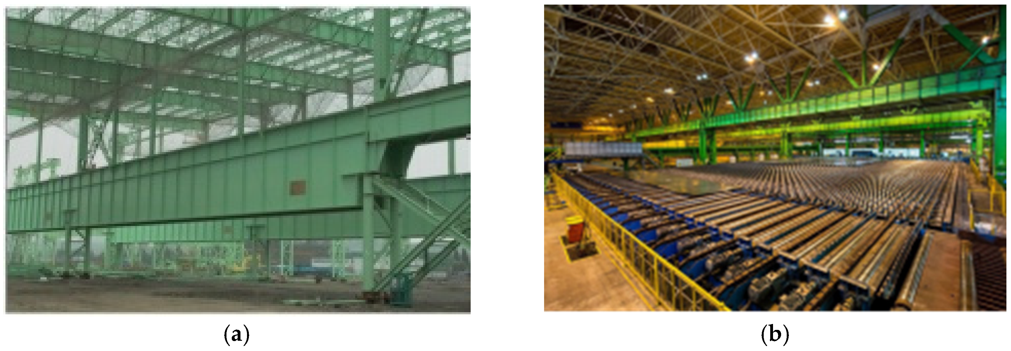
Figure 1. The comparison between the solid-web crane beam and bracket-crane truss structure: (a) solid-web crane beam; (b) bracket-crane truss structure.
Buildings 14 01994 g001
Figure 2. The dimensions of the bracket-crane truss: (a) the overall structural layout of the bracket-crane truss; (b) detailed section view of the multi-web member connected integral node along section 1-1.
Buildings 14 01994 g002
Figure 3. Local enlarged view of the multiweb member connected integral node.
Buildings 14 01994 g003
Figure 4. Illustration of crane wheel loads.
Buildings 14 01994 g004
Figure 5. Illustration of load conditions.
Buildings 14 01994 g005
Figure 6. Illustration of boundary conditions.
Buildings 14 01994 g006
Figure 7. Solid model of the support node.
Buildings 14 01994 g007
Figure 8. The multiscale finite element model for the three nodes: (a) coupling between beam element and a solid node; (b) left support node; (c) node with only one web member; (d) node with multiple web members.
Buildings 14 01994 g008aBuildings 14 01994 g008b
Figure 9. Axial force comparison: (a) frame model axial force calculation results (in N); (b) multiscale finite element model axial force calculation results (in N).
Buildings 14 01994 g009
Figure 10. Displacement comparison: (a) frame model displacement calculation results (in meters); (b) multiscale finite element model displacement calculation results (in meters).
Buildings 14 01994 g010aBuildings 14 01994 g010b
Figure 11. Annotation of the weld positions in integral nodes: (a) annotation of the support node; (b) annotation of the node with only one web member; (c) annotation of the node with multiple web members.
Buildings 14 01994 g011
Figure 12. Force transmission paths at the node with multiweb members.
Buildings 14 01994 g012
Figure 13. Force transmission paths of the node with only one vertical web member.
Buildings 14 01994 g013
Figure 14. Force transmission paths of the left support node.
Buildings 14 01994 g014
Figure 15. Component comparison of the node with multiweb members.
Buildings 14 01994 g015
Figure 16. Force transmission path verification of the node with multiweb members: (a) horizontal weld force transmissions; (b) vertical weld force transmissions.
Buildings 14 01994 g016
Figure 17. Component comparison of the node with only one web member.
Buildings 14 01994 g017
Figure 18. Force transmission path verification of the node with only one web member: (a) horizontal weld force transmissions; (b) vertical weld force transmissions.
Buildings 14 01994 g018
Figure 19. Component comparison of the left support node.
Buildings 14 01994 g019
Figure 20. Force transmission path verification of the support node: (a) horizontal weld force transmissions; (b) vertical weld force transmissions.
Buildings 14 01994 g020
Figure 21. Weld force formula verification of the node with multiweb members: (a) horizontal weld force transmissions; (b) vertical weld force transmissions.
Buildings 14 01994 g021
Figure 22. Weld force formula verification of the node with only one web member.
Buildings 14 01994 g022
Figure 23. Weld force formula verification of the support nodes: (a) horizontal weld force transmissions; (b) vertical weld force transmissions.
Buildings 14 01994 g023
Table 1. Table of cross-section information.
Structural ComponentsCross-Sectional ProfilesMaterialElastic ModulusPoisson’s Ratio
Diagonal bracing at the edgeH800 × 700 × 20 × 35Q355C210,000 MPa0.3
Diagonal bracingH800 × 600 × 16 × 30
Vertical bracingH800 × 350 × 16 × 25
Upper chord box beamH800 × 800 × 20 × 25
Table 2. Load cases and load combinations of the bracket-crane truss.
Load TypesStandard ValuePartial Load Factors
Strength and StabilityFatigue
Self-weight9.8 × Mass1.3-
Roof Dead Load
(Applied as Nodal Forces)
300 kN1.3-
Roof Live Load
(Applied as Nodal Forces)
250 kN1.5-
Crane Load on Span A1568 kN for one crane1.5 (two cranes adjacent)-
Crane Load on Span B1548 kN for one crane1.5 (two cranes adjacent)1.3 (one crane)
Disclaimer/Publisher’s Note: The statements, opinions and data contained in all publications are solely those of the individual author(s) and contributor(s) and not of MDPI and/or the editor(s). MDPI and/or the editor(s) disclaim responsibility for any injury to people or property resulting from any ideas, methods, instructions or products referred to in the content.