
Seismic Performance of Drop-In Anchors in Concrete under Shear and Tension


Abstract
1. Introduction
2. Research Significance
3. Prediction Models of Anchor Capacity in Tension and Shear
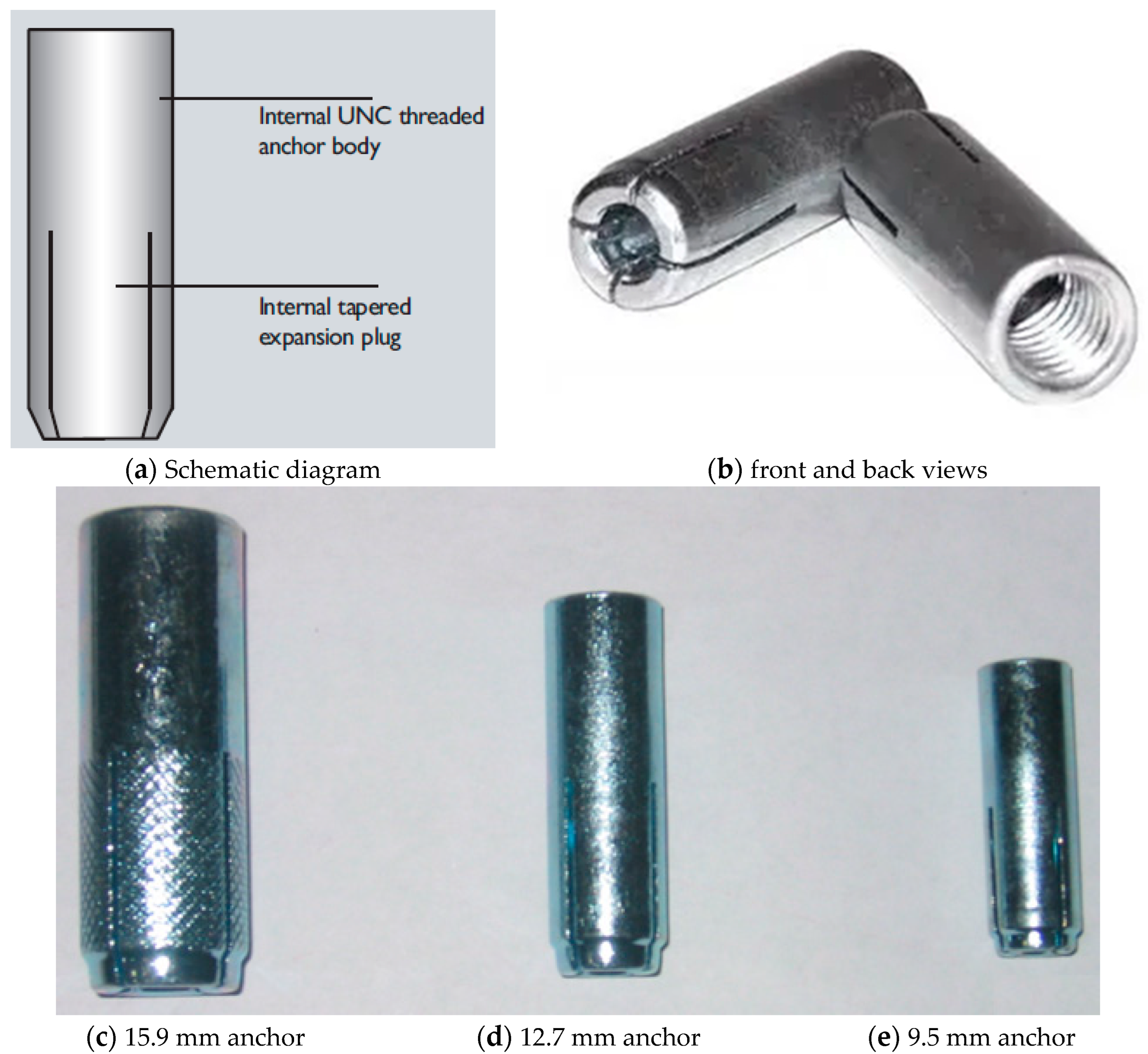
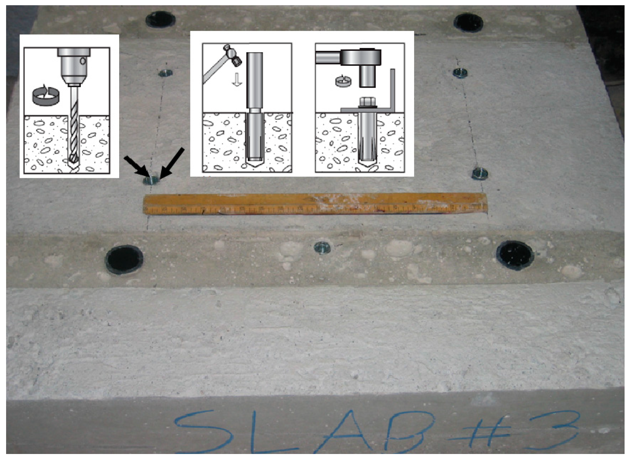
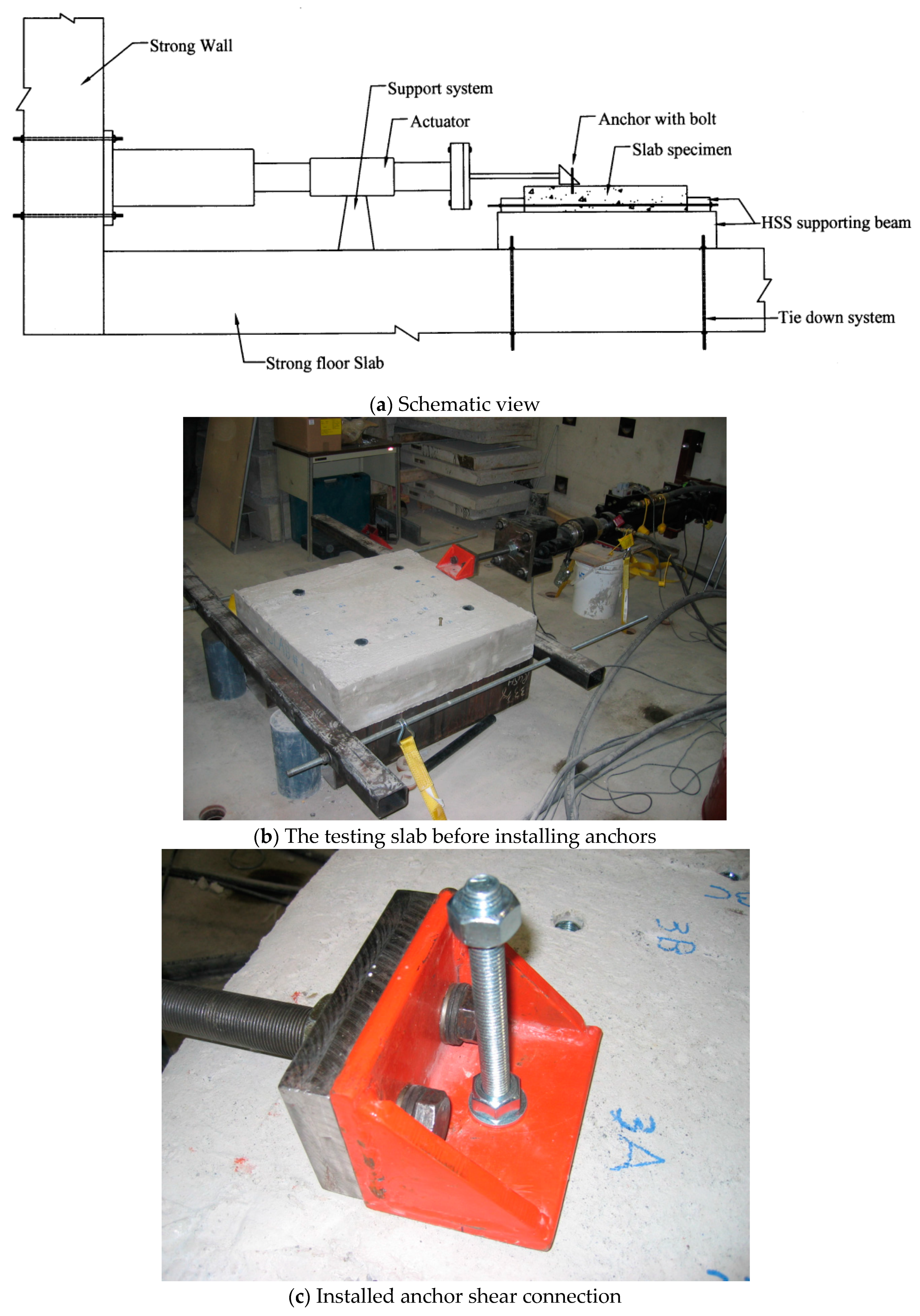
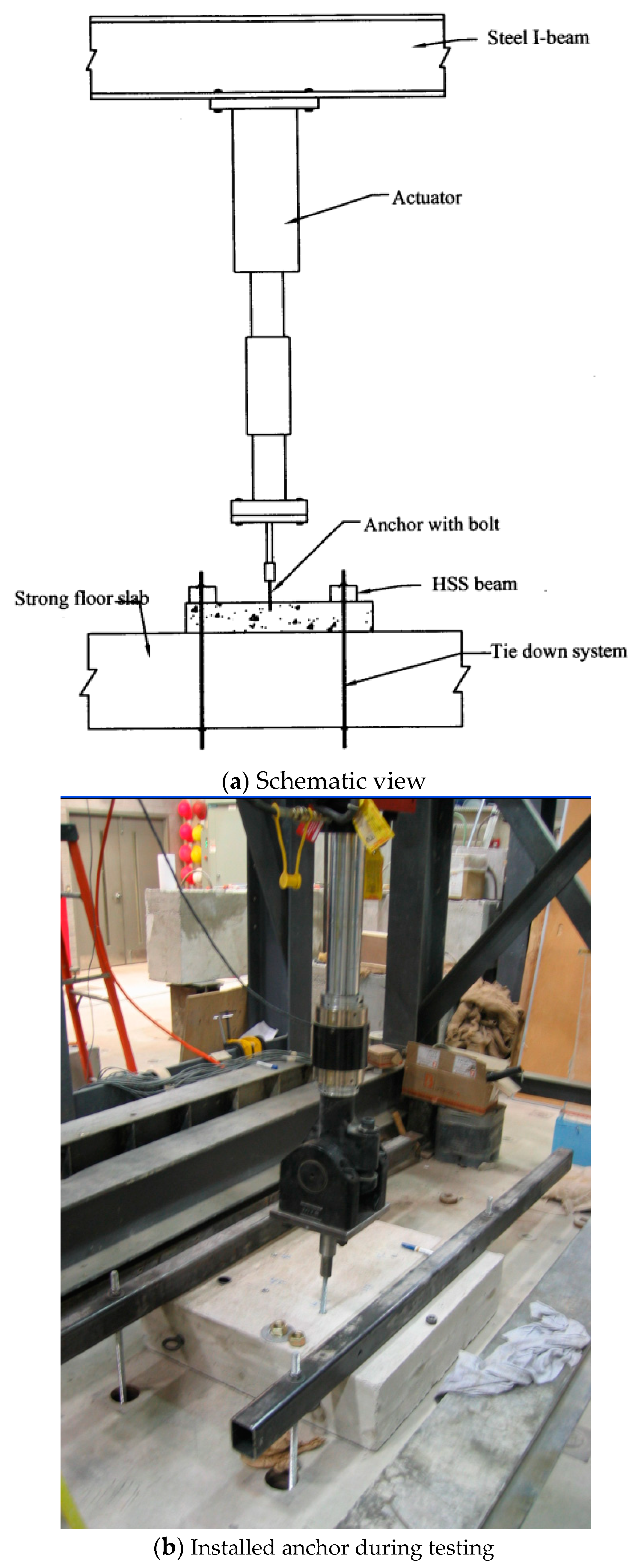
4. Experimental Program
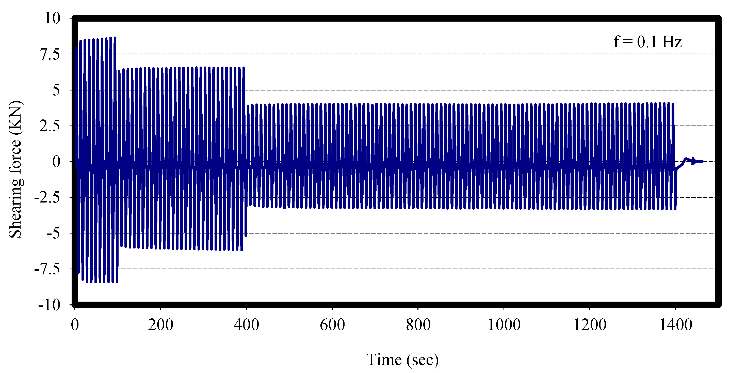
- The loading frequency is to be in the range of 0.1 to 2.0 Hz.
- Each seismic cycle test must consist of at least 5 identical anchors.
- A reference ultimate static load for shear and tension is to be established to determine the loading amplitude for cyclic tests.
- After the seismic cycles are completed, each anchor is loaded in tension and shear, as applicable, to its ultimate capacity.
5. Experimental Results
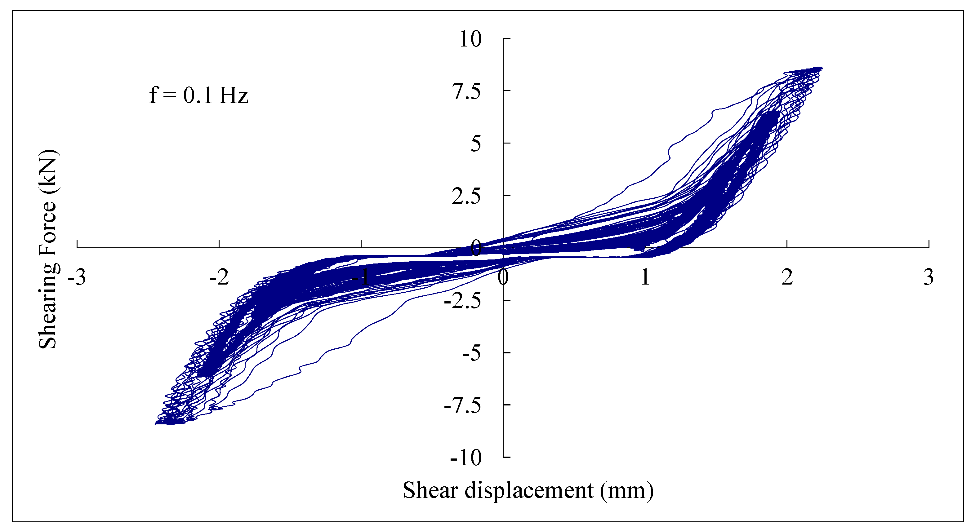
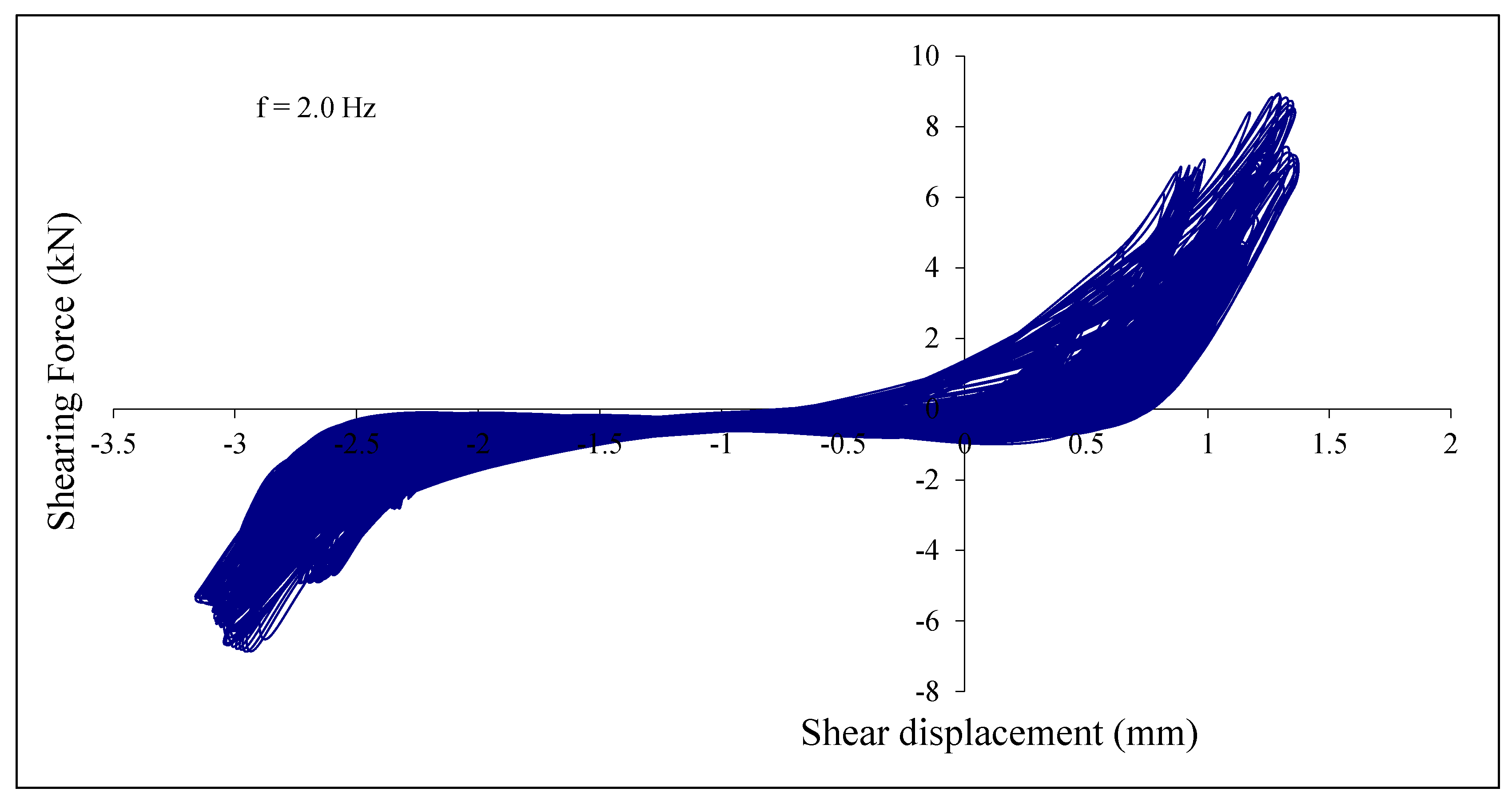
5.1. Cyclic Shear Load Test Results
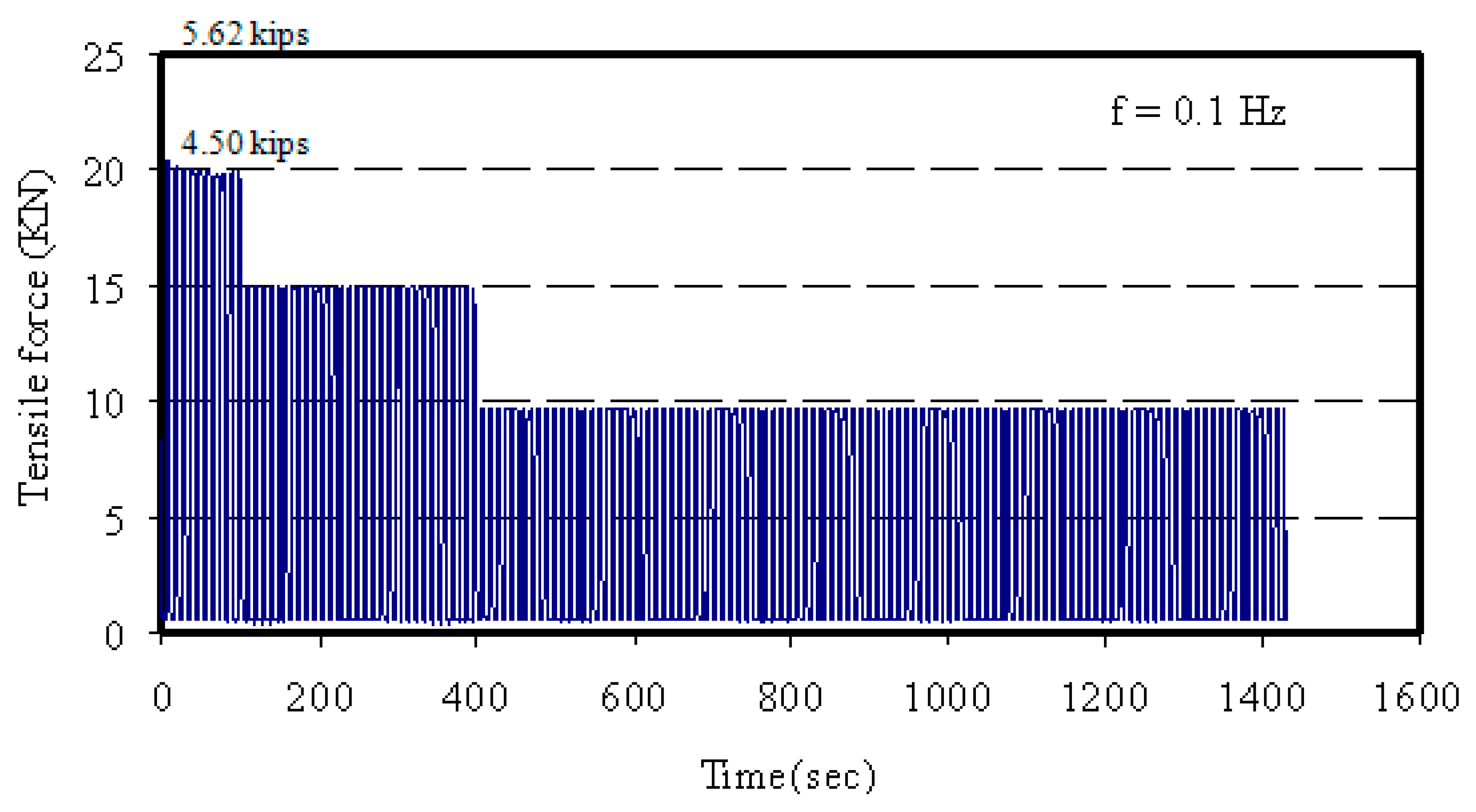
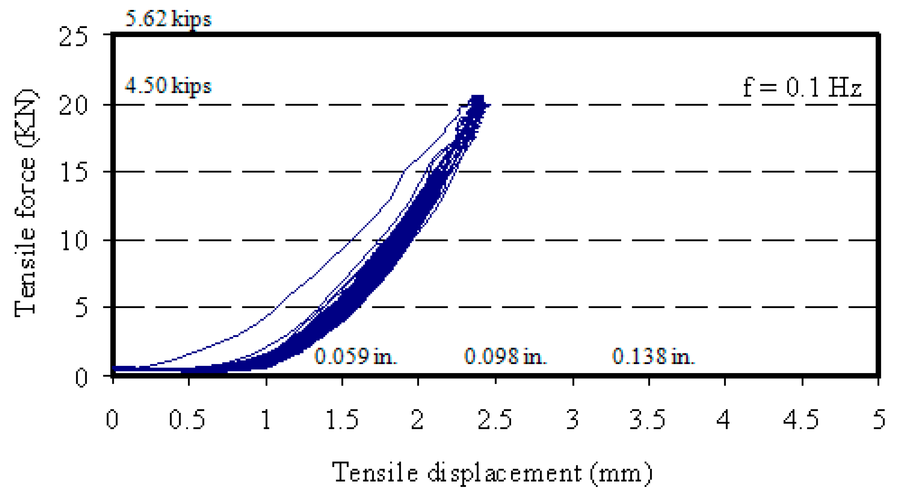
5.2. Cyclic Tension Test Results
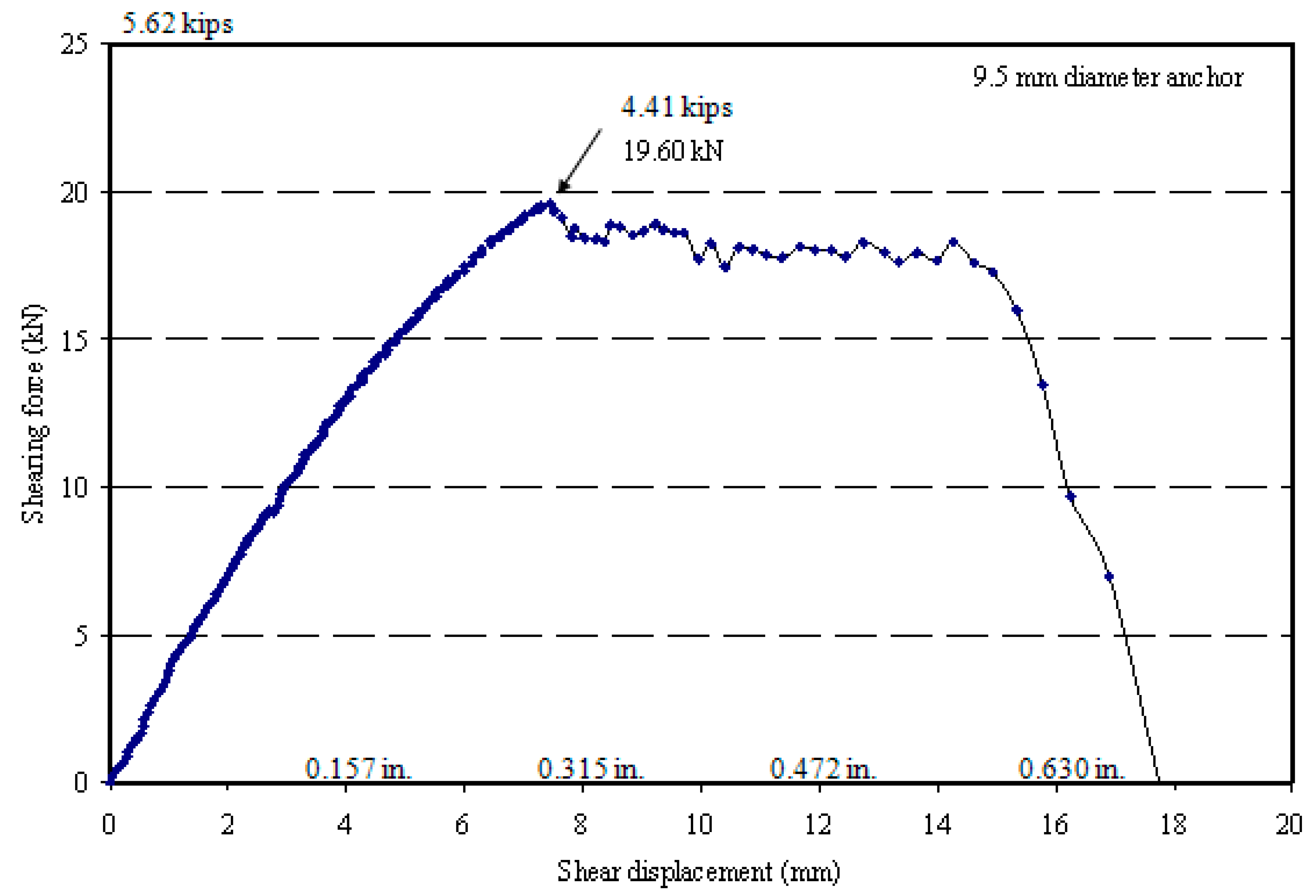
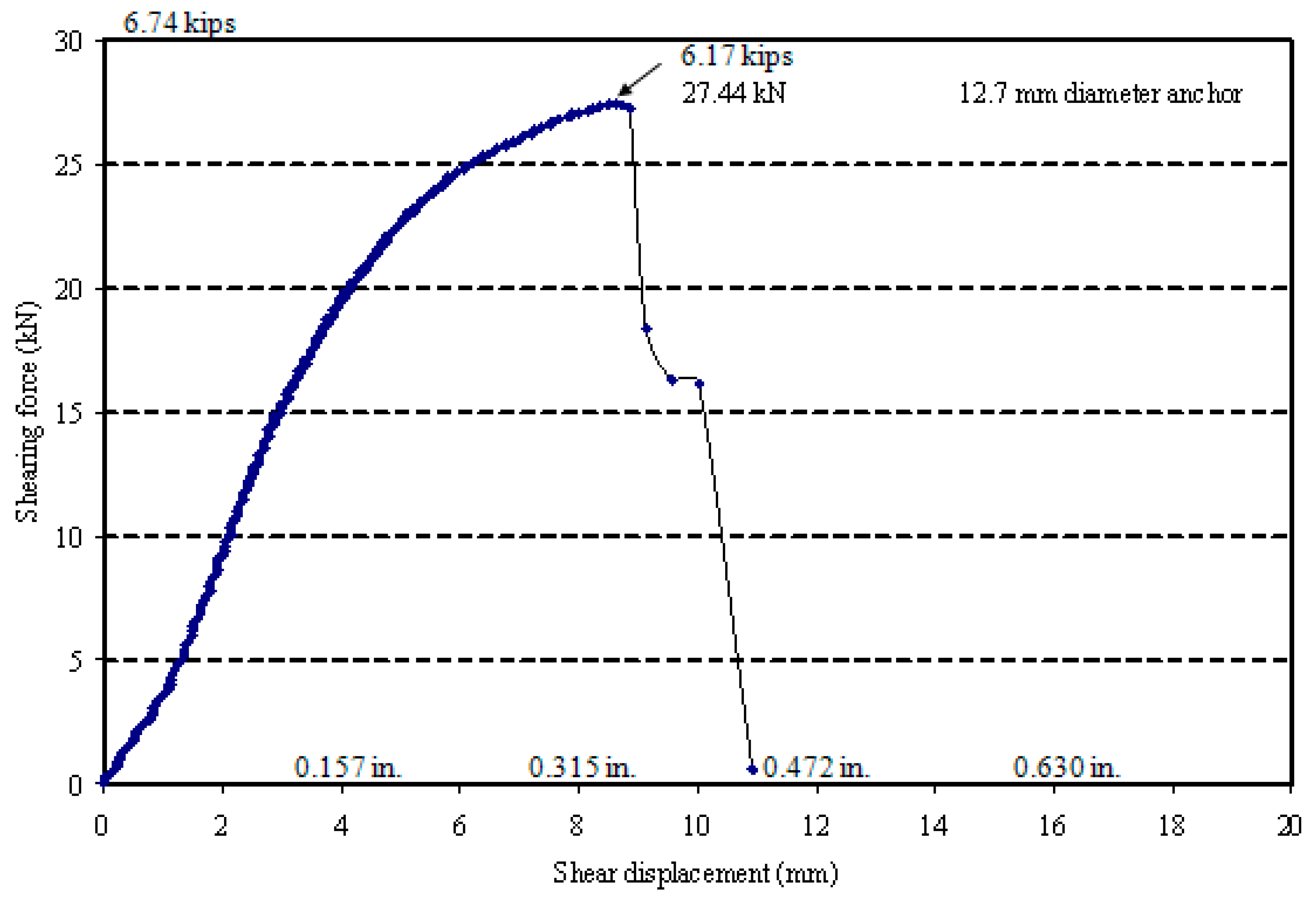
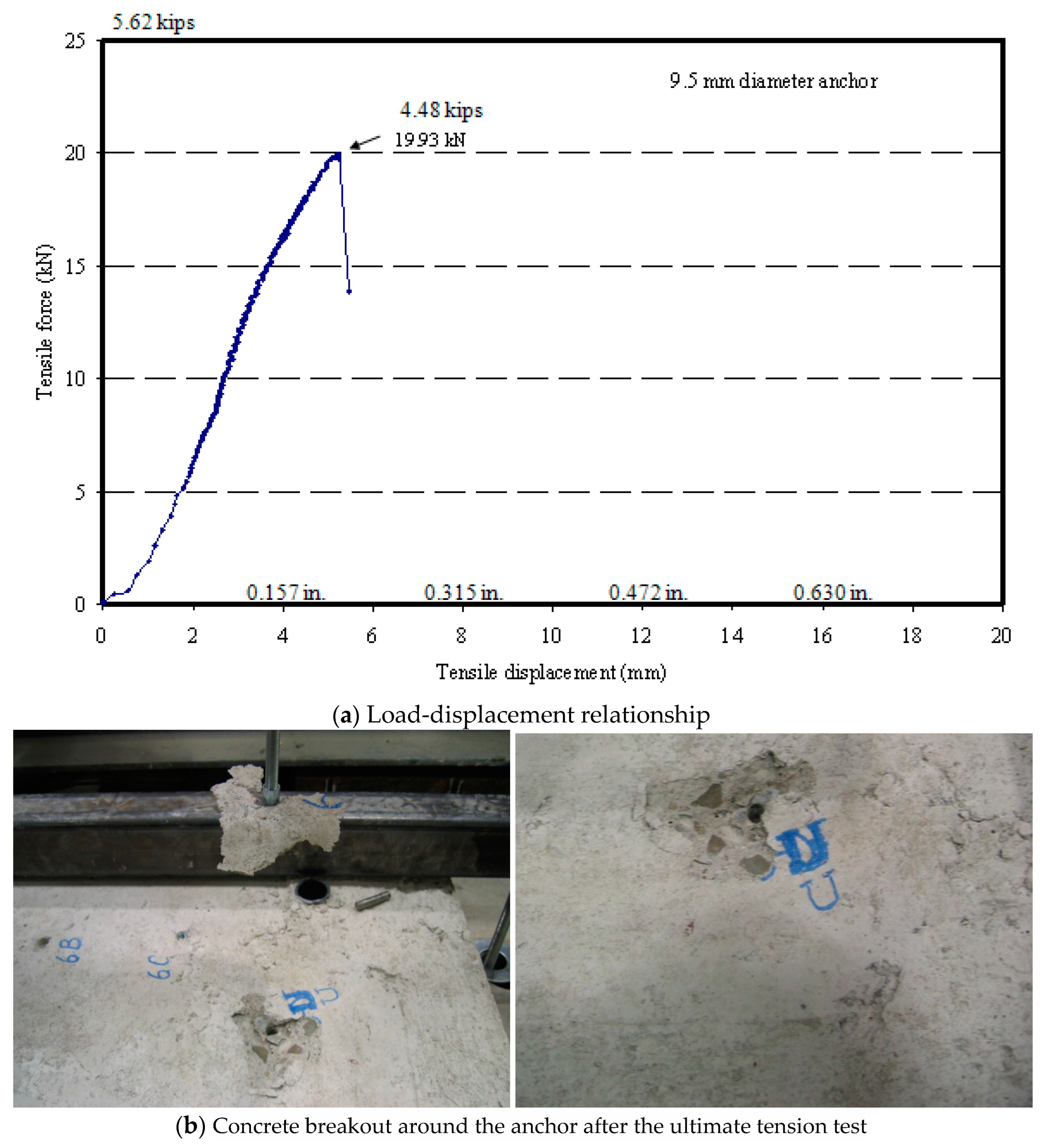
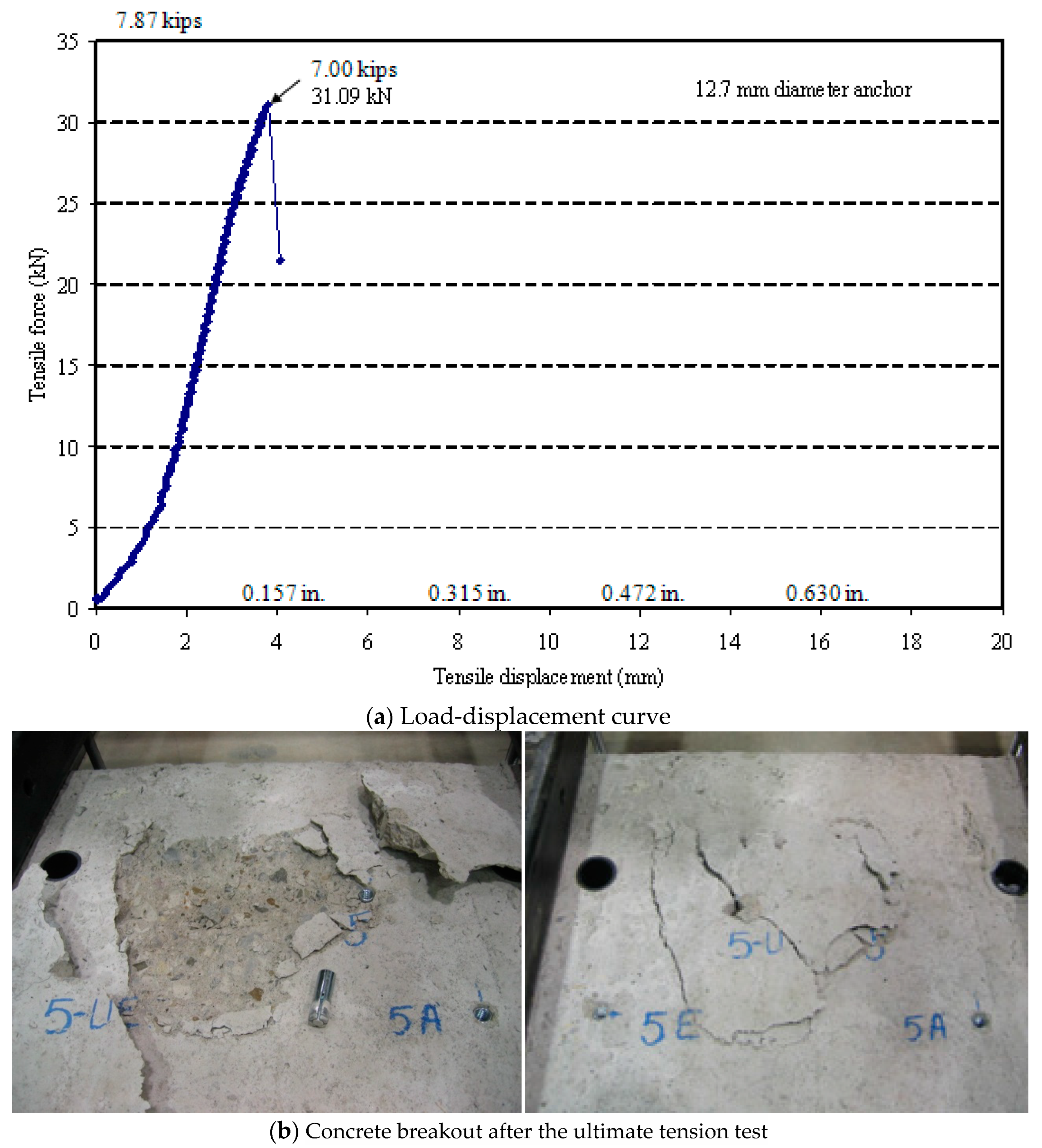
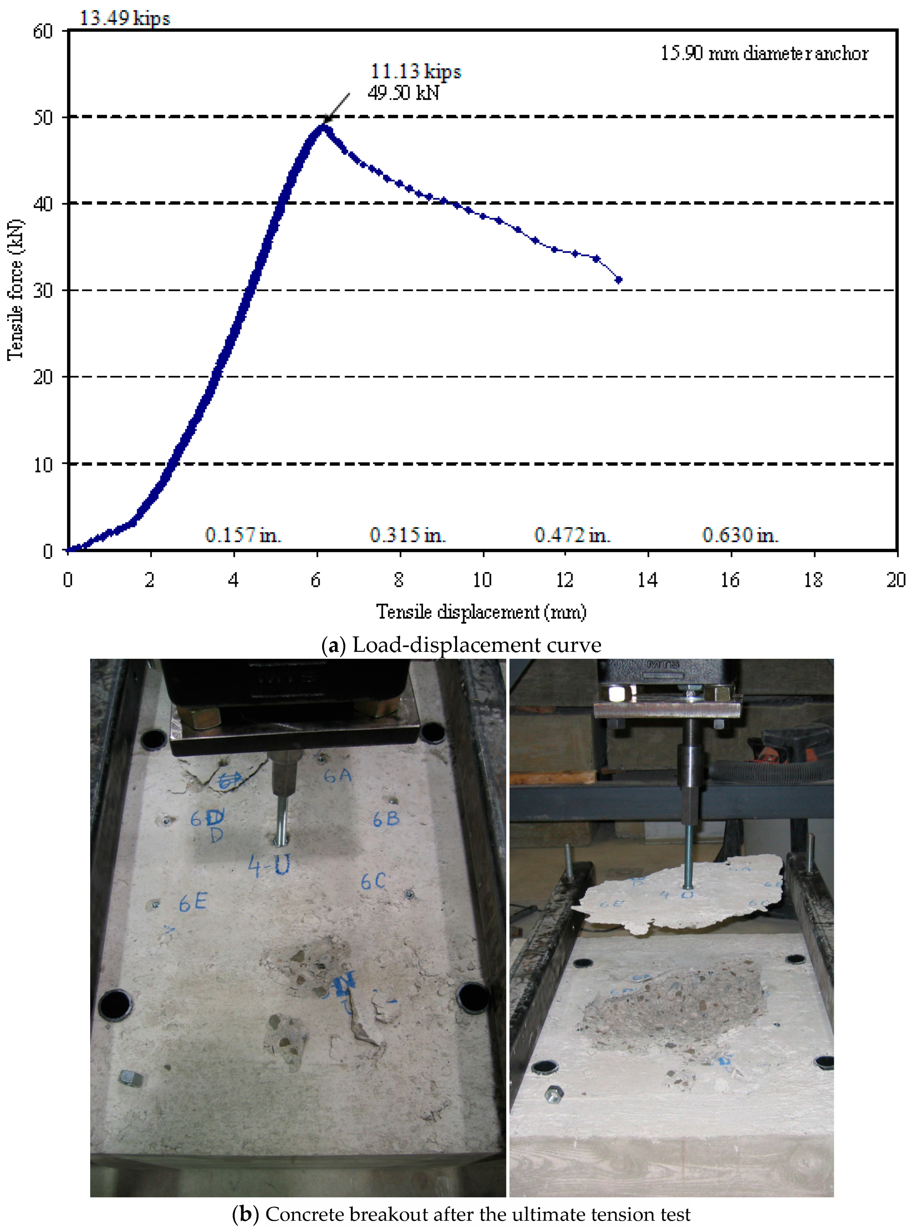
5.3. Ultimate Load Test Results
6. Accuracies of Various Empirical Formulas in Predicting the Anchor Capacity in Shear and Tension
7. Conclusions
- No tension failure occurred at the end of the cyclic load tests for all the tested anchors. The anchors sustained the cyclic tension loading with minimal residual inelastic axial displacement.
- The drop-in anchors resisted seismic tension and shear loading with frequency ranges between 0.1 and 2.0 Hz.
- Inconsistency in cyclic shear test results was observed in the case of the greater anchor sizes due to a fracture in the connecting threaded bar to the actuator’s fixture.
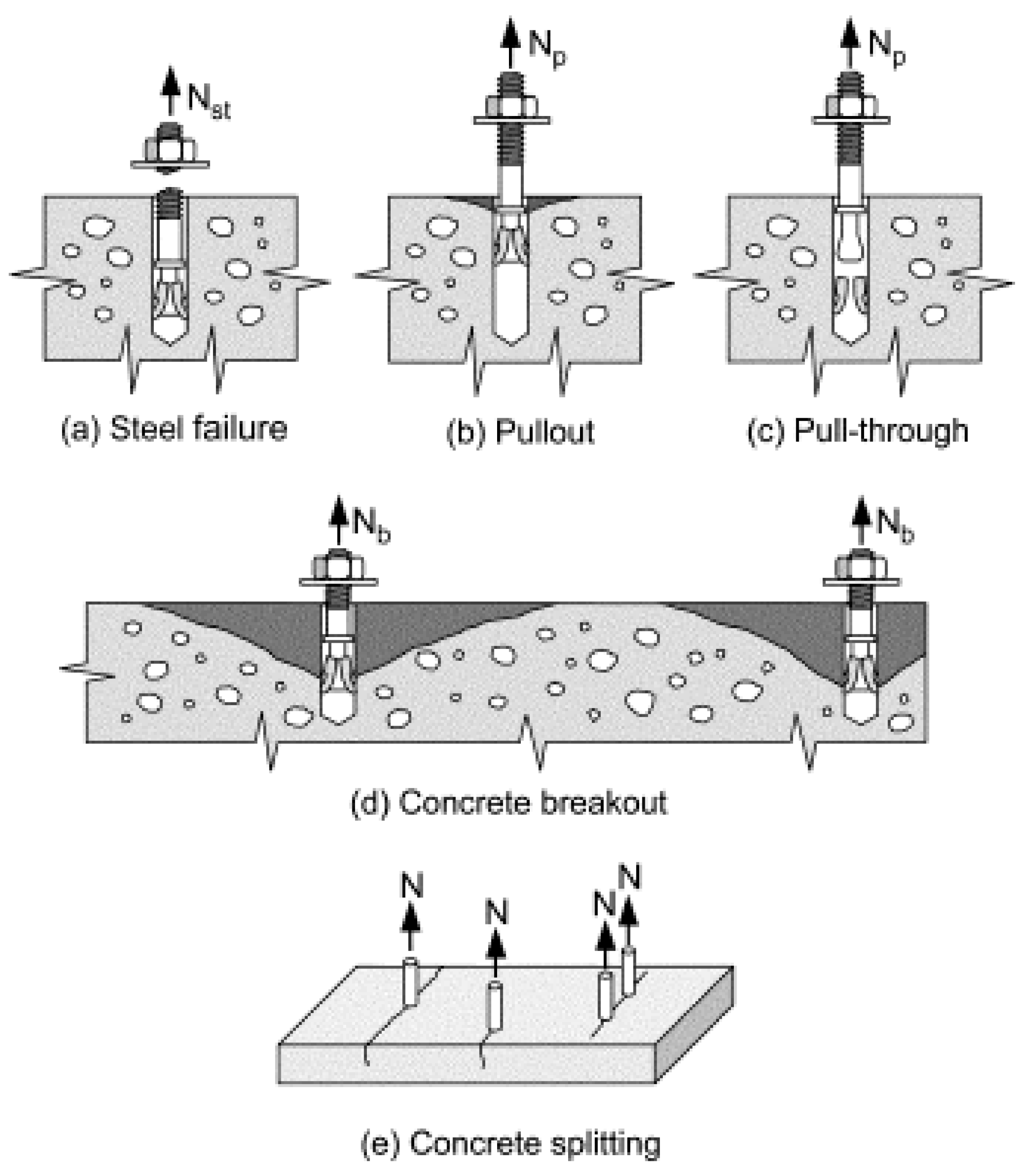
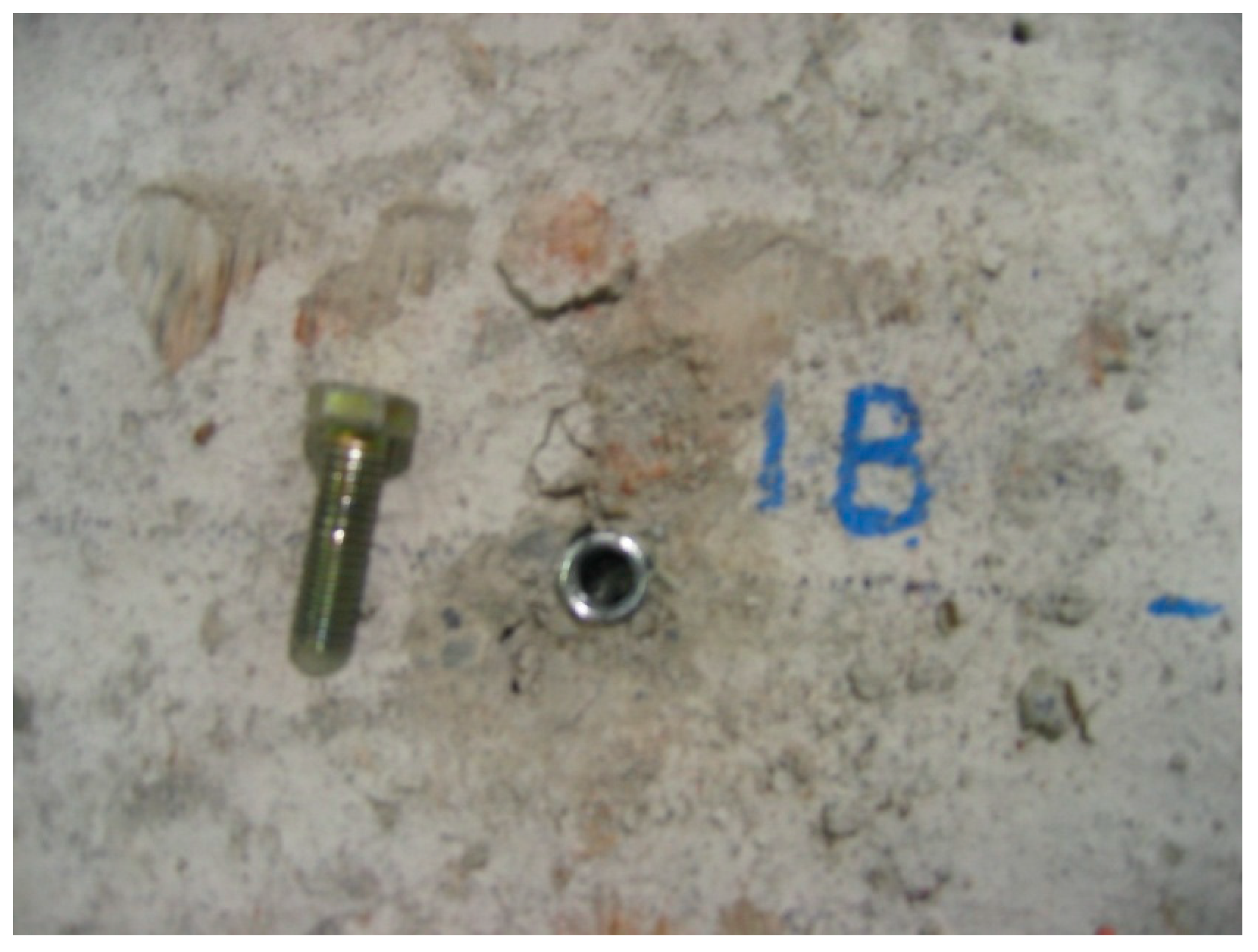
- The anchors subjected to increasing shear forces failed in shear fracture proceeded by concrete spall. In contrast, those subjected to increasing tension forces failed due to concrete breakout failure.
- The experimental ultimate loads obtained from static shear and tension tests were generally greater than those specified in the manufacturer’s technical manual.
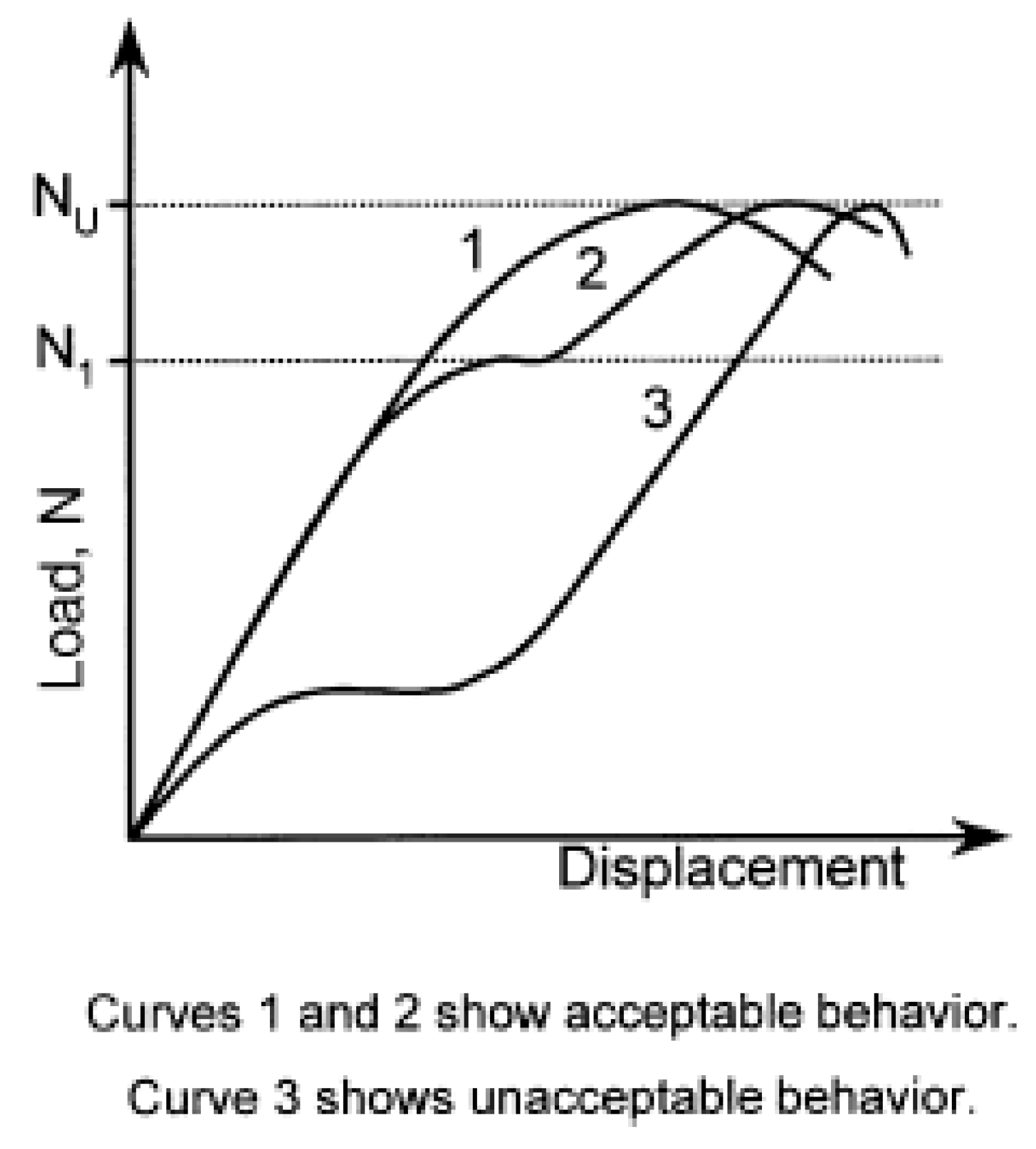
- The corresponding failure modes were consistent with the typical ones predicted by the standard ACI 355.2-04. The tensile load–displacement behaviors of all the tested anchors satisfied the standard requirements for an acceptable tested anchor behavior as per the standard ACI 355.2-04.
- The theoretical models to predict the concrete breakout of anchors in tension were all found to predict a lower capacity than experimental ultimate loads, which are conservative in design. The model recommended by Eligehausen et al. [51] predicted the closest results to the experimental values.
- It was found that the factor kcp equal to 1 was significantly conservative in predicting the pry-out shear resistance of anchors recommended by ACI 318-19. A value of kcp equal to 2 or slightly smaller than 2 is likely to predict a better pry-out capacity with the experimental results. On the other hand, the steel shear resistance theoretical model prescribed by ACI 318-19 could closely predict the resistance of the anchors that failed under steel shear proceeded by concrete spall.
Author Contributions
Funding
Data Availability Statement
Acknowledgments
Conflicts of Interest
Abbreviations
| ANc | Failure area of concrete with a single/group of anchors; for the calculation of concrete breakout strength subjected to tension |
| ANco | Failure area of concrete with a single anchor; for the calculation of concrete breakout strength subjected to tension when not limited by spacing or edge distance |
| AVc | Actual projected area (base) of the concrete fracture-cone-adjacent side of the concrete member |
| AVco | Idealized projected area (base) of the concrete fracture cone as a half pyramid that equals 3c1 times 1.5c1 |
| Ase | Cross-sectional area of the anchor |
| c1 | Edge distance in the loading direction (equals the greater of c2/1.5 and h/1.5 for anchors in concrete members with c2 < 1.5c1 and h < 1.5c1) |
| c2 | Edge distance perpendicular to the loading direction |
| da | Anchor diameter |
| fc′ | Concrete compressive strength |
| f’cc | Concrete cube compressive strength = |
| fut | Tensile strength of anchor steel |
| h | Thickness of the concrete member |
| hef | Anchor effective embedment depth |
| kc | Coefficient for basic concrete breakout strength subjected to tension |
| kcp | Coefficient for pry-out strength |
| le | Activated bearing length of anchor ≤ 8da (le equals anchor effective embedment for anchors with constant overall stiffness, and 2da is for expansion anchors with separated spacing and expansion sleeves) |
| Nb | Basic concrete breakout strength of single anchor subjected to tension |
| Ncb | Concrete breakout strength of anchors in tension |
| Neq | The maximum seismic tension test load, equal to 50% of the mean tension capacity in cracked concrete from reference tests |
| Ni | Equals (Neq + Nm)/2 |
| Nm | One-quarter of the mean tension capacity in cracked concrete |
| Vb1, Vb2 | Basic concrete breakout strength of single anchor subjected to shear |
| Vcb | Concrete breakout strength of anchors subjected to shear |
| Vcp | Concrete pry-out strength of a single anchor |
| Veq | Maximum seismic shear load calculated as one-half of the mean capacity in cracked concrete from calculated shear capacity or shear tests |
| Vi | Equals (Veq + Vm)/2 |
| Vm | One-quarter of the mean shear capacity in cracked concrete calculated from steel capacity or from test results |
| Vsa | Shear strength of a single anchor |
| λa | Modification factor for the type of concrete used |
| ψc | Modification factor accounting for the presence or absence of concrete cracks |
| ψcp | Modification factor of the tensile strength of post-installed anchors |
| ψed | Modification factor accounting for the effect of proximity to edges of concrete member |
| ψh | Modification factor for the shear strength of anchors located in concrete members with h < 1.5ca1 |
References
- ACI 355.1R-91; State-of-the-Art Report on Anchorage to Concrete. American Concrete Institute: Detroit, MI, USA, 1997.
- ACI 355.2-04; Qualification of Post-Installed Mechanical Anchors in Concrete. American Concrete Institute: Detroit, MI, USA, 2004.
- He, J.; Yao, L. Experimental Study on Mechanical Properties of Reinforced Soil and Frame Beam Anchor Combination System. Buildings 2024, 14, 1372. [Google Scholar] [CrossRef]
- Hosseini, S.; Astaraki, F.; Imam, S.M.R.; Chalabii, J.; Movahedi Rad, M. Investigation of Shear Strength Reduction Method in Slope Stability of Reinforced Slopes by Anchor and Nail. Buildings 2024, 14, 432. [Google Scholar] [CrossRef]
- Matsunaga, K.; Takase, Y.; Abe, T. Modeling of dowel action for cast-in and post-installed anchors considering bond property. Eng. Struct. 2021, 245, 112773. [Google Scholar] [CrossRef]
- UCAN. Drop-in Anchor Technical Manual; UNCAN Fastening Products Inc.: Toronto, ON, Canada, 2005. [Google Scholar]
- Wei, J.; Ying, H.; Yang, Y.; Zhang, W.; Yuan, H.; Zhou, J. Seismic performance of concrete-filled steel tubular composite columns with ultra high performance concrete plates. Eng. Struct. 2023, 278, 115500. [Google Scholar] [CrossRef]
- Huang, H.; Guo, M.; Zhang, W.; Huang, M. Seismic behavior of strengthened RC columns under combined loadings. J. Bridge Eng. 2022, 27, 05022005. [Google Scholar] [CrossRef]
- Yao, Y.; Huang, H.; Zhang, W.; Ye, Y.; Xin, L.; Liu, Y. Seismic performance of steel-PEC spliced frame beam. J. Constr. Steel Res. 2022, 197, 107456. [Google Scholar] [CrossRef]
- Zhang, X.; Liu, X.; Zhang, S.; Wang, J.; Fu, L.; Yang, J.; Huang, Y. Analysis on displacement-based seismic design method of recycled aggregate concrete-filled square steel tube frame structures. Struct. Concr. 2023, 24, 3461–3475. [Google Scholar] [CrossRef]
- Yang, L.; Ye, M.; Huang, Y.; Dong, J. Study on mechanical properties of displacement-amplified mild steel bar joint damper. Iran. J. Sci. Technol. Trans. Civ. Eng. 2023, 48, 2177–2190. [Google Scholar] [CrossRef]
- Huang, H.; Li, M.; Zhang, W.; Yuan, Y. Seismic behavior of a friction-type artificial plastic hinge for the precast beam–column connection. Arch. Civ. Mech. Eng. 2022, 22, 201. [Google Scholar] [CrossRef]
- Huang, H.; Li, M.; Yuan, Y.; Bai, H. Experimental research on the seismic performance of precast concrete frame with replaceable artificial controllable plastic hinges. J. Struct. Eng. 2023, 149, 04022222. [Google Scholar] [CrossRef]
- Zhang, J.; Zhang, C. Using viscoelastic materials to mitigate earthquake-induced pounding between adjacent frames with unequal height considering soil-structure interactions. Soil Dyn. Earthq. Eng. 2023, 172, 107988. [Google Scholar] [CrossRef]
- Klingner, R.; Mendonca, J.; Malik, J. Effect of reinforcing details on the shear resistance of anchor bolts under reversed cyclic loading. J. Proc. 1982, 79, 3–12. [Google Scholar]
- Tang, J.H.K.; Deans, J.J. Test criteria and method for seismic qualification of concrete expansion anchors. In Proceedings of the Fourth Canadian Conference on Earthquake Engineering, Vancouver, BC, Canada, 15–17 June 1983; pp. 58–69. [Google Scholar]
- Collins, D.M.; Klingner, R.E.; Polyzois, D. Load-Deflection Behavior of Cast-in-Place and Retrofit Concrete Anchors Subjected to Static, Fatigue, and Impact Tensile Loads; CTR 1126-1; Center for Transportation Research, University of Texas at Austin: Austin, TX, USA, 1989. [Google Scholar]
- Klingner, R.E.; Graves, H.L. Anchor Bolt Behavior and Strength During Earthquakes; US Nuclear Regulatory Commission (NRC): Washington, DC, USA, 1994. [Google Scholar]
- Ahmed, L.T.; Braimah, A. Behaviour of undercut anchors subjected to high strain rate loading. Procedia Eng. 2017, 210, 326–333. [Google Scholar] [CrossRef]
- Chen, Z.; Nassiri, S.; Lamanna, A.; Cofer, W. Investigation of pull-through and pullout failure modes of torque-controlled expansion anchors. ACI Struct. J. 2020, 117, 17–27. [Google Scholar] [CrossRef]
- Gallo, P.Q.; Moghaddasi, M.; Pampanin, S.; Bergmeister, K. Shake table tests of post-installed anchors with supplemental damping. ACI Struct. J. 2018, 115, 595–606. [Google Scholar] [CrossRef]
- Ghobarah, A.; Aziz, T. Seismic qualification of expansion anchors to Canadian nuclear standards. Nucl. Eng. Des. 2004, 228, 377–392. [Google Scholar] [CrossRef]
- Hoehler, M.S.; Mahrenholtz, P.; Eligehausen, R. Behavior of Anchors in Concrete at Seismic-Relevant Loading Rates. ACI Struct. J. 2011, 108, 238–247. [Google Scholar]
- Lotze, D.; Klingner, R.E.; Graves, H.L., III. Static behavior of anchors under combinations of tension and shear loading. In Proceedings of the International Symposium on Connections between Steel and Concrete, Stuttgart, Germany, 10–12 September 2001; pp. 118–128. [Google Scholar]
- Tarawneh, A.N.; Ross, B.E.; Cousins, T.E. Tensile behavior and design of adhesive anchors embedded in thin concrete members. PCI J. 2020, 65, 51–64. [Google Scholar] [CrossRef]
- Tarawneh, A.N.; Ross, B.E.; Cousins, T.E. Tensile Behavior and Design of Screw Anchors in Thin Concrete Members. ACI Struct. J. 2020, 117, 91–102. [Google Scholar] [CrossRef]
- Tarawneh, A.N.; Saleh, E.; Dwairi, H.M.; Majdalaweyh, S.A. Design and strength reduction factors calibration of adhesive anchors embedded in thin concrete members. Structures 2022, 40, 213–222. [Google Scholar] [CrossRef]
- Bang, J.S.; Kwon, Y.; Ahn, J.-H.; Yim, H.J. Pull-out behavior evaluation of torque-controlled expansion anchors under various installation conditions of concrete. Case Stud. Constr. Mater. 2022, 16, e00796. [Google Scholar] [CrossRef]
- Bokor, B.; Sharma, A. Numerical investigations on non-rectangular anchor groups under shear loads applied perpendicular or parallel to an edge. CivilEng 2021, 2, 692–711. [Google Scholar] [CrossRef]
- Nilforoush, R.; Nilsson, M.; Elfgren, L.; Ožbolt, J.; Hofmann, J.; Eligehausen, R. Tensile capacity of anchor bolts in uncracked concrete: Influence of member thickness and anchor’s head size. ACI Struct. J. 2017, 114, 1519–1530. [Google Scholar] [CrossRef]
- Obayes, O.; Gad, E.; Lee, J.; Pokharel, T.; Abdouka, K. Assessment of the tensile behaviour of cast-in headed anchors with void formers in early age concrete. Constr. Build. Mater. 2022, 317, 125851. [Google Scholar] [CrossRef]
- Cannon, R.W. Expansion anchor performance in cracked concrete. ACI Struct. J. 1981, 78, 471–479. [Google Scholar]
- Copley, J.D.; Burdette, E.G. Behavior of steel-to-concrete anchorages in high moment regions. J. Proc. 1985, 82, 180–187. [Google Scholar]
- Eligehausen, R.; Fuchs, W.; Mayer, B. Load bearing behavior of anchor fastenings in tension. Betonw. Fert. 1987, 12, 826–832. [Google Scholar]
- Eligehausen, R.; Balogh, T. Behavior of fasteners loaded in tension in cracked reinforced concrete. ACI Struct. J. 1995, 92, 365–379. [Google Scholar]
- Rodriguez, M. Behavior of anchors in uncracked concrete under static and dynamic tensile loading. Master’s Thesis, University of Texas at Austin, Austin, TX, USA, 1995. [Google Scholar]
- Rodriguez, M.; Lotze, D.; Gross, J.H.; Zhang, Y.-G.; Klingner, R.; Graves, H. Dynamic behavior of tensile anchors to concrete. Struct. J. 2001, 98, 511–524. [Google Scholar]
- Hashimoto, J.; Takiguchi, K. Experimental study on pullout strength of anchor bolt with an embedment depth of 30 mm in concrete under high temperature. Nucl. Eng. Des. 2004, 229, 151–163. [Google Scholar] [CrossRef]
- Muratli, H.; Klingner, R.E.; Graves, H.L., III. Breakout capacity of anchors in concrete—Part 2: Shear. Struct. J. 2004, 101, 821–829. [Google Scholar]
- Shirvani, M.; Klingner, R.E.; Graves, H.L., III. Breakout capacity of anchors in concrete part 1: Tension. Struct. J. 2004, 101, 812–820. [Google Scholar]
- Abdul-Hamid, A.; Braimah, A.; Tai, F. Impact load effects on screw anchors in concrete. Eng. Struct. 2022, 251, 113491. [Google Scholar] [CrossRef]
- Neupane, C.C.; Lee, J.; Pokharel, T.; Tsang, H.-H.; Gad, E. Development and challenges in finite element modelling of post-installed anchors in concrete. Struct. Infrastruct. Eng. 2023, 1–22. [Google Scholar] [CrossRef]
- Mahrenholtz, P.; Wood, R.L. European Seismic Performance Categories C1 and C2 for Post-Installed Anchors. ACI Struct. J. 2020, 117, 31. [Google Scholar]
- Liu, H.; Zhao, J.; Davis, T. Novel adhesive anchoring system through engineered adhesive-concrete interface. Structures 2021, 33, 947–956. [Google Scholar] [CrossRef]
- AC01–Acceptance Criteria for Expansion Anchors in Concrete and Masonry Elements; ICC Evaluation Service Inc.: Whittier, CA, USA, 2010.
- ASTM E 488-96; Standard Test Methods for Strength of Anchors in Concrete and Masonry Elements. American Society for Testing and Materials (ASTM): West Conshohocken, PA, USA, 1996.
- ACI 318-19; Building Code Requirements for Structural Concrete and Commentary. ACI: Farmington Hills, MI, USA, 2019.
- Eligehausen, R.; Mallée, R.; Silva, J.F. Anchorage in Concrete Construction; John Wiley & Sons: Berlin, Germany, 2006. [Google Scholar]
- Eligehausen, R.; Pusill-Wachtsmuth, P. State-of-the-Art: Fixing Technology for Reinforced Concrete; IVBH Report S-19/82; IABSE: Berlin, Germany, 1982. (In German) [Google Scholar]
- Pusill-Wachtsmuth, P. Load-Bearing Behaviour of Metal Expansion Anchors under Axial Tension for Concrete and Splitting Failure. Ph.D. Thesis, Universität Stuttgart, Stuttgart, Germany, 1982; pp. 1992–1994. (In German). [Google Scholar]
- Eligehausen, R.; Fuchs, W.; Mayer, B. Load-bearing behaviour of fastenings with anchors under tension loading. Beton + Fert.-Tech. 1987, 12, 826–832. (In German) [Google Scholar]
- ACI 349–90; Code Requirements for Nuclear Safety Related Concrete Structures, Appendix B–Steel Embedments. American Concrete Institute: Farmington Hills, MI, USA, 1990.
- Paschen, H.; Schönhoff, T. Investigation on Shear Bolts in Concrete Made from Concrete Steel; Deutscher Ausschuss für Stahlbeton: Berlin, Germany, 1983; pp. 105–149. (In German) [Google Scholar]
- Eligehausen, R.; Mallée, R.; Rehm, G. Befestigungstechnik (Fastening Technique) Betonkalender 1997; Part II; Ernst Sohn: Berlin, Germany, 1997; pp. 609–753. [Google Scholar]
- Eligehausen, R.; Hofmann, J. Experimentelle und Numerische Untersuchungen an Befestigungen am Bauteilrand unter Querlast; Institut für Werkstoffe im Bauwesen, Universität Stuttgart, for the Deutsche Forschungsgemeinschaft: Berlin, Germany, 2003. [Google Scholar]
- Shaikh, A.F.; Yi, W. In-place strength of welded headed studs. PCI J. 1985, 30, 56–81. [Google Scholar] [CrossRef]


| Main Formulas | Definition of Parameters |
|---|---|
| Concrete breakout strength of anchor subjected to tension ACI 318-19 where: ACI 349-90 Eligehausen et al. [51] Eligehusen and Pusill-Wachtsmuth [49] Pusill-Wachtsmuth [50] | (normal concrete) (for post-installed anchors) (for cast-in anchors, upper limit) (for single anchors far from the edge) = effective embedment depth = 13.5 for expansion anchors = anchor diameter for torque-controlled expansion anchor = anchor edge distance along the force = thickness of the concrete member that anchors are attached to = cross-sectional area = ultimate tensile strength for expansion anchors = concrete cube compressive strength (Eligehausen et al. [48]) = concrete cylinder compressive strength Note: in all formulas, the parameters are in SI units of mm or MPa |
| Concrete breakout strength of anchor subjected to shear ACI 318-19 where: Eligehausen et al. [54] Eligehausen and Hofmann [55] where: Paschen and Schonhoff [53] ACI 349-90 Shaikh and Whayong [56] | |
| Nominal shear strength ACI 318-19 | |
| Concrete pry-out strength of anchor subjected to shear ACI 318-19 (for cast-in and expansion anchors) |
| Anchor Size, mm | Ultimate Load | Allowable Load | 1.33× Allowable Load | Cyclic Shear Test Loads | ||
|---|---|---|---|---|---|---|
| Vu (kN) | Va (kN) | Vre (kN) | Veq (kN) | Vi (kN) | Vm (kN) | |
| 10 Cycles | 30 Cycles | 100 Cycles | ||||
| 9.5 | 18.40 | 4.60 | 6.12 | 9.20 | 6.90 | 4.60 |
| 12.7 | 24.00 | 6.00 | 7.98 | 12.00 | 9.30 | 6.70 |
| 15.9 | 40.00 | 10.00 | 13.30 | 20.00 | 15.60 | 11.10 |
| Anchor Size, mm | Ultimate Load | Allowable Load | 1.33× Allowable Load | Cyclic Tension Test Loads | ||
|---|---|---|---|---|---|---|
| Nu (kN) | Na (kN) | Nre (kN) | Neq (kN) | Ni (kN) | Nm (kN) | |
| 10 Cycles | 30 Cycles | 100 Cycles | ||||
| 9.5 | 17.60 | 4.40 | 5.85 | 8.80 | 6.60 | 4.20 |
| 12.7 | 27.80 | 6.95 | 9.24 | 13.90 | 10.40 | 6.90 |
| 15.9 | 38.60 | 9.65 | 12.83 | 19.30 | 14.50 | 9.70 |
| Anchor Size, mm | Test Type | Test Failure Load, kN | Displacement at Failure, mm | Failure Mode * |
|---|---|---|---|---|
| 9.5 | Shear | 19.60 | 7.52 | SF&CS |
| 12.7 | Shear | 27.44 | 8.70 | SF&CS |
| 15.9 | Shear | 48.20 | 15.54 | SF&CS |
| 9.5 | Tension | 19.93 | 5.22 | CB |
| 12.7 | Tension | 31.09 | 3.79 | CB |
| 15.9 | Tension | 49.50 | 6.20 | CB |
| Action under Consideration | Mode of Failure and the Associated Available Models | For Anchor Size of 9.5 mm (kN) | For Anchor Size of 12.7 mm (kN) | For Anchor Size of 15.9 mm (kN) |
|---|---|---|---|---|
| Tension | Concrete breakout strength of anchors in tension | |||
| Average experimental load | 19.9 | 31.1 | 49.5 | |
| Manufacturer’s listed failure load | 19.6 | 27.4 | 48.2 | |
| ACI 318-19, if kc = 7 | 11.7 | 17.7 | 25.6 | |
| ACI 318-19, if kc = 10 | 16.7 | 25.2 | 36.5 | |
| Eligehausen et al. [51] | 17.5 | 26.4 | 38.2 | |
| Eligehusen and Pusill-Wachtsmuth [49] | 14.7 | 22.1 | 32.0 | |
| Pusill-Wachtsmuth [50] | 12.3 | 21.4 | 34.9 | |
| ACI 349-90 | 7.7 | 13.3 | 21.7 | |
| Shear | Normal shear strength | |||
| ACI 318-19 | 17.9 | 31.9 | 50.0 | |
| Concrete breakout strength of anchors in shear | ||||
| Average experimental load | 19.6 | 27.4 | 48.2 | |
| Manufacturer’s listed failure load | 18.4 | 24.0 | 40.0 | |
| ACI 318-19 | 35.0 | 40.5 | 45.3 | |
| Eligehausen et al. [54] | 33.2 | 38.4 | 43.0 | |
| Eligehausen and Hofmann [55] | 39.4 | 41.3 | 43.0 | |
| Paschen and Schonhoff [53] | 61.2 | 61.2 | 61.2 | |
| ACI 349-90 | 70.8 | 70.8 | 70.8 | |
| Shaikh and Whayong [56] | 50.1 | 50.1 | 50.1 | |
| Concrete pry-out strength of anchors in shear | ||||
| ACI 318-19, if kcp = 1 | 11.7 | 17.7 | 25.6 | |
| ACI 318-19, if kcp = 2 | 23.4 | 35.3 | 51.2 | |
Disclaimer/Publisher’s Note: The statements, opinions and data contained in all publications are solely those of the individual author(s) and contributor(s) and not of MDPI and/or the editor(s). MDPI and/or the editor(s) disclaim responsibility for any injury to people or property resulting from any ideas, methods, instructions or products referred to in the content. |
© 2024 by the authors. Licensee MDPI, Basel, Switzerland. This article is an open access article distributed under the terms and conditions of the Creative Commons Attribution (CC BY) license (https://creativecommons.org/licenses/by/4.0/).
Share and Cite
Sennah, K.; Azimi, H.; Ahmed, M.; Hamoda, A. Seismic Performance of Drop-In Anchors in Concrete under Shear and Tension. Buildings 2024, 14, 2021. https://doi.org/10.3390/buildings14072021
Sennah K, Azimi H, Ahmed M, Hamoda A. Seismic Performance of Drop-In Anchors in Concrete under Shear and Tension. Buildings. 2024; 14(7):2021. https://doi.org/10.3390/buildings14072021
Chicago/Turabian StyleSennah, Khaled, Hossein Azimi, Mizan Ahmed, and Ahmed Hamoda. 2024. "Seismic Performance of Drop-In Anchors in Concrete under Shear and Tension" Buildings 14, no. 7: 2021. https://doi.org/10.3390/buildings14072021
APA StyleSennah, K., Azimi, H., Ahmed, M., & Hamoda, A. (2024). Seismic Performance of Drop-In Anchors in Concrete under Shear and Tension. Buildings, 14(7), 2021. https://doi.org/10.3390/buildings14072021