Article

An Investigation into the Variables Influencing the Structural Bamboo Architecture Using Filled Concrete and Cement Mortar

1
State Key Laboratory of Subtropical Building and Urban Science, Architectural Design and Research Institute, South China University of Technology, Guangzhou 510640, China
2
Department of Civil Engineering, Guangdong University of Technology, Guangzhou 510006, China
*
Authors to whom correspondence should be addressed.
Buildings 2024, 14(7), 2029; https://doi.org/10.3390/buildings14072029
Submission received: 30 May 2024 / Revised: 21 June 2024 / Accepted: 28 June 2024 / Published: 3 July 2024
(This article belongs to the Section Building Materials, and Repair & Renovation)

Abstract

:
Bamboo, as a green building material, plays a vital role in construction. Bamboo has good properties and appearance, making it highly attractive for building structures and designs. Since the compressive capacity of bamboo is considerably lower than its tensile capacity, with the ratio typically ranging between 300% to 900%, this limits its application dimensions in construction. Therefore, filling the original bamboo structural members with specific materials or applying different connection methods can not only maintain the appearance of the bamboo structure but also improve its compressive capacity and overall durability, thus expanding the application range of bamboo structural members and enhancing the performance of the architectural design process. Two hollow bamboo specimens were among the eight BFC specimens tested for this paper. Key components such as transverse stiffeners, steel bars, filler materials, and bamboo nodes were examined for their influence on the specimens’ ductility, peak strain, ultimate bearing capacity, and failure mechanisms. The test results showed that the ratio of the ultimate bearing capacity of BFC specimens to hollow bamboo samples could reach up to 538%, while the peak strain differences were minimal. A non-linear finite element model was developed and its accuracy confirmed based on the test results. This work proposes a new approach to determine the final axial compressive capacity of BFC columns by creating an elastic model of transversely isotropic cylinders. As a result, the primary goal of this study is to establish a foundation for more scientific building design techniques and procedures by examining the axial compression mechanics of structural bamboo filled with cement and concrete (BFC) and how it influences building design.

1. Introduction

Bamboo is a natural biomaterial and a green material for construction [1,2,3,4,5]. Bamboo is a cheap material that can be produced in large quantities for only $0.07 per kilogram. It grows quickly—three to five years are needed for it to reach the desired strength and toughness—and is highly weatherable. It also releases 0.25 kg CO2/kg of carbon into the atmosphere for every unit of energy consumed, which is significantly less than the 2.2–2.8 kg CO2/kg that steel releases [2,3,4,5,6,7,8,9,10].
In the fields of construction engineering, transportation, and aerospace, there are numerous materials designed with superior mechanical properties, such as metal carbide and petroleum-based products. However, these materials have drawbacks, including high energy consumption, environmental pollution, high cost, and the use of nonrenewable resources [11,12,13,14]. Thus, there is a lot of interest in creating novel engineering materials that are lightweight, inexpensive, and highly effective for usage as green construction materials [15,16,17,18].
Bamboo architecture is evolving in two directions, driven by modern technology [19]: first, it uses bamboo to mimic contemporary trusses, space grids, and other structural shaping to realize large-span bamboo architecture; second, it improves traditional construction methods using the principles of contemporary structural mechanics in conjunction with local genes to make it develop in a more environmentally friendly and humanistic direction. Since bamboo is a very brittle material, many architects are actively exploring ways to make it stronger and to challenge the span and height of structures using flexible materials.
Bamboo has been found to have the same fiber orientation, which makes it prone to cracking under high external force. It also creates a lot of issues when the hollow circular cross sections of bamboo come together. Furthermore, bamboo structures have hollow cross sections with varying tensile strengths, which lowers their compressive, rather than tensile, capacity. Therefore, in order to offer important insights into the creation of bamboo structures as well as buildings, it is necessary to fill them with particular materials (Appendix A), which can improve bamboo’s overall performance and compressibility [20,21].
While there have been instances of using filler materials to enhance the weight-bearing capacity of bamboo structures, research on the mechanical performance in this area remains limited. Li, Long, et al. [22] conducted pertinent experimental investigations and proposed a straightforward yet efficient reinforcement plan for bamboo tubes. However, a systematic, theoretical, and unified design method has yet to be established, significantly hindering the application of bamboo tubes in construction. This paper conducted further tests, utilizing ABAQUS 6.14 software for finite element simulation to investigate the axial compression performance of the proposed scheme. A novel mechanical model was developed to determine the axial compression-bearing capacity of BFC short-root columns based on the interaction between bamboo tubes and concrete, providing a solid theoretical basis and reliable numerical simulation methods for the application and development of BFC in bamboo construction. Additionally, this study explores the factors influencing bamboo construction, offering a scientific foundation and methodological guidelines for architectural design.

2. Materials and Methods

2.1. Materials

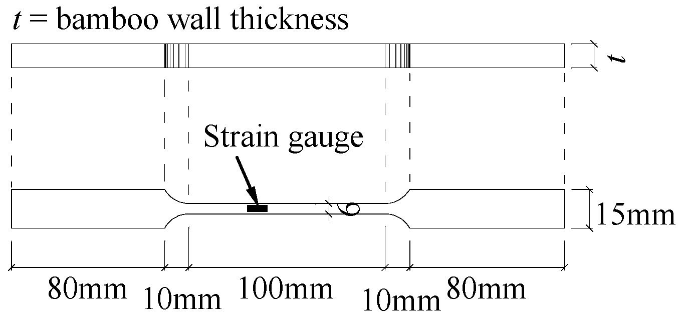
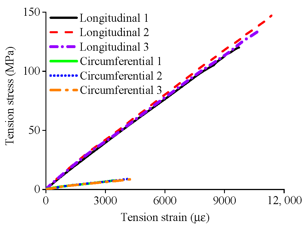
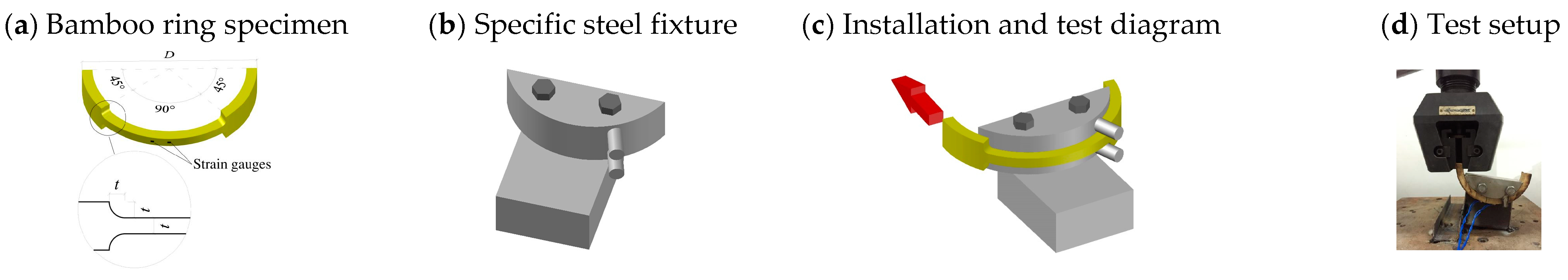
2.1.1. Physical and Mechanical Properties of Bamboo Elements

To accurately design and predict the performance of structures utilizing bamboo, it is crucial to understand and measure the physical and mechanical properties of bamboo and its engineered derivatives (Table 1). In the last few decades, significant research efforts have been devoted to examining properties such as density, moisture content, compressive strength, flexural strength, and the modulus of rupture in bamboo elements. In this section, the physical and mechanical properties of bamboo culm, engineered bamboo elements, and BRC elements have been has been summarized in detail [11].
As mentioned in Table 2, the material of the vertical compression model of the bamboo tube was isotropic with a Poisson’s ratio of 0.3 and an ideal elastoplastic constitutive relation. Its elastic modulus was obtained directly from the longitudinal tensile test of longitudinal bamboo strips, and was 13.70 GPa. Its yield stress was 0.8 times the average intensity value of the bamboo tube compression test, which was 24.76 MPa. The hoop tension model of the bamboo tube adopted a solid model with isotropic material, a Poisson’s ratio of 0.3, and an ideal elastoplastic constitutive relation. Its elastic modulus was measured directly by the hoop tensile test of bamboo, which was 2.11 GPa. Its yield stress was the average value of the hoop tensile test, which was 8.36 MPa.

2.1.2. Concrete Properties

The concrete damage plasticity model defined in ABAQUS 6.14 was used for the analysis. The dilation angle, flow potential eccentricity, and ratio of the second stress invariant on the tensile meridian and f b / f co were 30°, 0.1, 0.667, and 1.16, respectively. In addition, the viscosity parameter for concrete was 0.0005. The concrete damage plasticity model of the ABAQUS defined in ABAQUS/Standard 6.4 is used in the analysis, i.e., the dilation angle ψ , the flow potential eccentricity, the ratio of the second stress invariant on the tensile meridian K c , and f b / f co are, respectively, 30°, 0.1, 1.16, and 0.667. In addition, the viscosity parameter is 0.0005 for the concrete. While the model automatically includes the strength enhancement resulting from lateral confinement, the default softening criterion and flow rule of the concrete damage plasticity model in ABAQUS 6.14 are insufficient to adequately simulate the stiffness deterioration and strain softening response observed in confined concrete [23,24]. One feasible approach is to modify the stress–strain relationship by replacing the peak strain of confined concrete ε cc with the strain of unconfined concrete ε co . According to GB 50010-2010 [25], the compressive stress–strain relationship of concrete is determined by the following formulas:
σ = ( 1 d c ) E c ε
d c = { 1 ρ c n n 1 + x n x 1 1 ρ c α c ( x 1 ) 2 + x x > 1
ε co = ( 700 + 172 f co ) × 10 6
E c = 4700 f co
α c = 0.157 f co 0.785 0.905
where, x = ε ε cc , ρ c = f co E c ε cc , n = E c ε cc E c ε cc f co .
According to the research of Candappa DC et al. [26], the peak strain of confined concrete ε cc is related to the lateral pressure f r it receives as follows:
ε cc = [ 1 + k f r f co ] ε co
The calculation of the peak strain of unconfined concrete ε co is represented by Equation (3). In this calculation, it is necessary to consider the impact of the horizontal stiffener and steel cage on the peak strain of the concrete. Through regression analysis, it was determined that the value of k was 50 when there was no horizontal stiffener or steel cage in the specimens. However, when a horizontal stiffener or steel cage was included in the specimens, the value of k was found to be 85.
Furthermore, the tensile behavior of the concrete also follows the formula specified in GB 50010-2010 [25] as follows:
σ = ( 1 d t ) E c ε
d t = { 1 ρ t [ 1.2 0.2 x 5 ] x 1 1 ρ t α t ( x 1 ) 1.7 + x x > 1
ε t , r = f t 0.54 × 65 × 10 6
α t = 0.312 f t 2
where x = ε ε t , r , ρ t = f t E c ε t , r , f t can be taken as 0.3 f co ( 2 / 3 ) [27].

2.1.3. Cement Mortar Properties

Cement mortar, which also utilizes the concrete damage plasticity model in ABAQUS, requires a different selection for its compressive stress–strain relationship. It can be calculated using the following formula [28]:
y = { 0.4 x 3 0.2 x 2 + 1.6 x 0 x 1 x 11 ( x 1 ) 2 + x x 1
where y = σ f co , x = ε ε cc ; ε cc is calculated in Equations (3) and (6). According to the test data, the k value of confined cement mortar is 15.
The formula for the tensile stress–strain relationship of cement mortar is as follows [29]:
y = { 1.2 x 0.2 x 6 0 x 1 x 0.312 f t 2 ( x 1 ) 1.7 + x x 1
where y = σ f t , x = ε ε t , r .

2.1.4. Steel Properties

All materials used for reinforcement and the horizontal stiffener were considered isotropic, with a Poisson’s ratio of 0.3, and followed an ideal elastoplastic constitutive relation. The elastic modulus and yield stress values were determined through tensile tests.

2.2. Methods

2.2.1. Finite Element Modeling
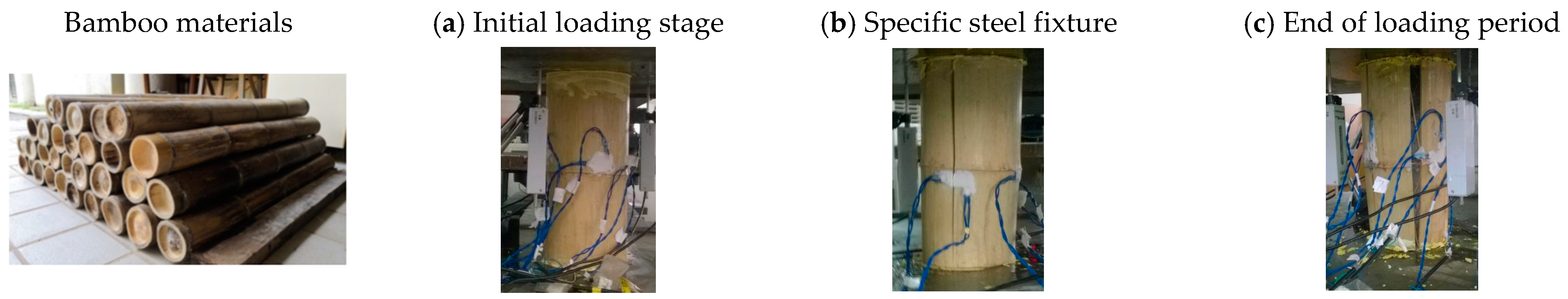
Preliminary experimental results show that prior to bamboo tube cracking, the restraint mechanism of concrete in BFC members is similar to that of concrete filled steel tubes. This section proposes a method to model BFC members using ABAQUS finite element software. The aim of this methodology is to ensure that the load–strain curves obtained from finite element simulation are in good agreement with the ascending stage of the experimental curves and align with the downward trend, thus providing reliable recommendations for the efficient modeling and design of BFC members.
To simulate the concrete behavior, eight-node brick elements (C3D8R) were employed. The top end was permitted to axially slide freely in order to replicate the actual loading conditions in the experiment. Given that bamboo tube components are orthotropic materials with certain unknown material properties, a discrete modeling approach was adopted. Specifically, the vertical compressive behavior and hoop tensile behavior of the bamboo tube were simulated separately. The vertical compression behavior of the bamboo tube was simulated using four-node shell elements (S4R). The tube wall was not in contact with the concrete, and the boundary conditions at the top and bottom were the same as those applied to the concrete.
For modeling the hoop tension behavior of the bamboo tube, eight-node brick elements (C3D8R) were utilized. The inner wall of the bamboo tube and the concrete were in a “surface-to-surface” contact, with a friction coefficient of 0.2 [30]. A “hard” contact in the normal direction was established, employing a small sliding formulation and overclosure removal in the slave adjustment. Imperfections and residual stresses of the short columns were neglected [31]. The hoop tension model of the bamboo tube was free at both ends, without any contact.
The horizontal stiffener was simulated using eight-node brick elements (C3D8R). To simplify the model and reduce computation, the horizontal stiffener was connected to the outer wall of the bamboo tube at both ends. The reinforcement was modeled using two-node truss elements (T3D2). The rebars were embedded into the concrete, assuming perfect bonding between the rebars and the concrete.
In the analysis, synchronized displacement was applied to the top of the concrete model and the vertical compression model of the bamboo tube to induce axial load and shortening deformation, allowing for the characterization of their relationship.

2.2.2. Test

This study evaluates the integration of bamboo into concrete and cement mortar and its subsequent effects on material properties. Bond strength is critical for determining the necessary reinforcement to prevent concrete cracking and structural failure. Typically, pull-out tests measure slip or bond strength, which arises from mechanical interlocking, friction, and chemical adhesion between the reinforcing bar and the cement matrix. Split bamboo, with a higher frictional surface, outperforms whole round bamboo. However, bamboo’s propensity for water absorption presents a significant challenge; it absorbs moisture, expands horizontally by 2% to 5% and longitudinally by about 0.05% during casting, and then contracts after curing. This cyclic expansion and contraction creates voids, weakens bond strength, and leads to concrete cracking. Furthermore, bamboo’s natural composition makes it prone to degradation in moist and alkaline environments [32].
As previously described, supplementary experimental research was carried out on the axial compressive performance of BFC components to further study their mechanical properties and the influence of bamboo nodes on them. A total of 8 specimens were designed for testing, taking into account the influences of internal filling materials (plain concrete, cement mortar, and reinforced concrete), bamboo nodes, and transverse connections on the BFC components. The specimen design height and diameter are L o = 300 mm and D o = 150 mm, with an aspect ratio of 2 for design convenience. To facilitate the introduction of concrete and cement mortar into the BFC specimens, all of the bamboo diaphragms were penetrated. Due to the natural characteristics of bamboo tubes, some deviations and variability in the ideal design dimensions are inevitable when using them as part of specimens. Therefore, the size parameters are based on actual measurements. To minimize the influence of specimen size variability on the test results, the bamboo used for the specimens was selected from the same location and age of moso bamboo. Following the method described by Li, Long et al. [22], the bamboo culms for this test were meticulously chosen from a single batch of moso bamboo, all of which were 6 m long and 5 years old, to ensure precise specimen dimensions. Furthermore, these bamboo culms were air-dried for 3 months to achieve a moisture content of less than 15%. The size parameters were determined based on actual measurements, considering the diameter (D) and wall thickness (t) at different positions of the head, middle, and tail, as well as both ends of each specimen. A careful selection of bamboo tubes ensured that the size differences at each part of the bamboo tubes in this test were controlled within 5%. The basic parameters of the specimens are shown in Table 3 and Figure 1.
In the nomenclature of specimens, B represents bamboo, 0C represents no infill material, 1C represents concrete as the infill material, 1M represents mortar as the infill material, 0R represents no reinforcement, 1R represents one steel reinforcement, 2R represents a steel reinforcement cage, 0N represents no bamboo node, 1N represents one bamboo node, 0H represents no horizontal stiffener, and 1H represents one horizontal stiffener.
Furthermore, since bamboo is an orthotropic material with different properties in different directions, the tensile strength of bamboo parallel to the grain is significantly greater than that perpendicular to the bamboo fibers, requiring additional testing. There are several methods for determining the transverse tensile strength of bamboo. This study adopted the method of pulling specially shaped bamboo rings on a specific steel fixture to obtain the transverse tensile stress–strain curve of bamboo [33], as shown in Figure 2. The schematics of the specific specimen shapes and fixture are shown in Figure 3. To enable the fixtures and bamboo ring specimens to fit closely and the contact surfaces to be as smooth as possible to ensure accurate measured data, the steel fixtures were custom-made according to the precise dimensions of the bamboo ring specimens and polished.
Figure 3 illustrates the nearly linear elastic behavior of bamboo in both the longitudinal and transverse directions. The longitudinal tensile elastic modulus of bamboo strips was 13.70 GPa. Its average tensile stress and maximum strain were 147.06 MPa and 1.07%, respectively. Figure 4a illustrates the dimensions of three specially-made bamboo rings and the positions of the strain gauges on them. Figure 4b shows the specific steel fixture that was used. Figure 4c illustrates the installation and testing of the rings on fixtures, with red arrows indicating the direction of tensile loading. Figure 4d presents the test setup. Prior to testing, the rings and the fixture were lubricated to minimize friction. Loaded at 0.02 mm/min, the rings yielded an average transverse tensile strength, modulus, and maximum strain of 8.36 MPa, 2.11 GPa, and 0.40%, respectively.

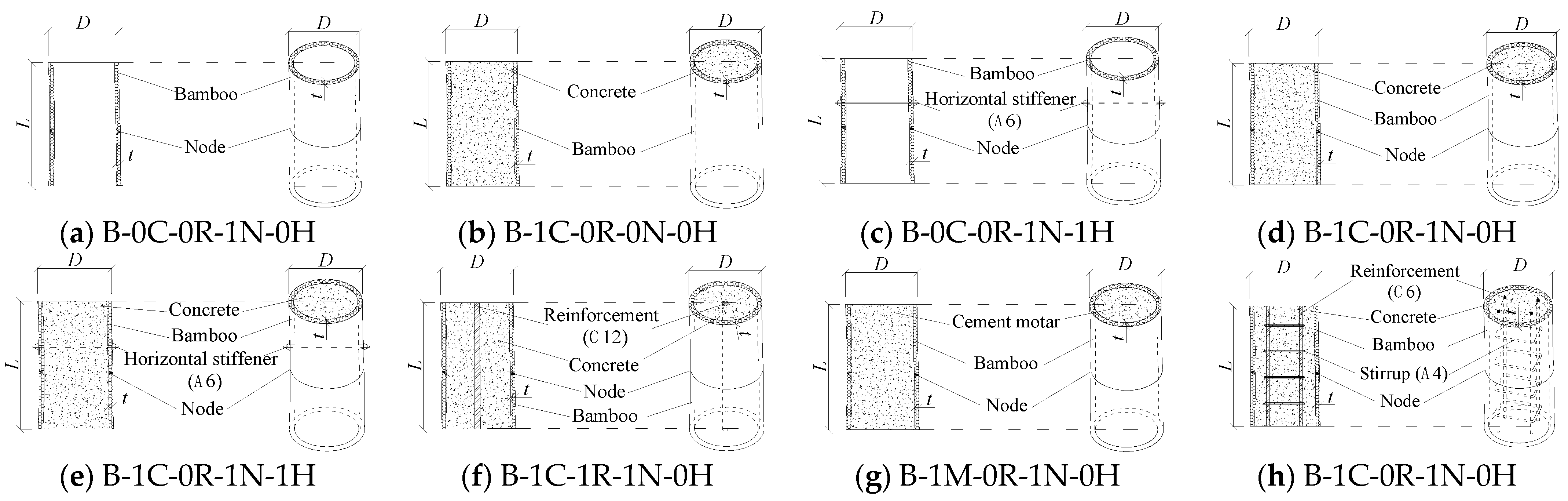
2.2.3. Structural Bamboo Filled with Concrete

Self-compacting concrete was used in the experiment. According to ASTM C39/C39M [34], three standard concrete cylinders were prepared; their average strength was 36.62 MPa. Three standard cement mortar cubes were also prepared and tested, with an average strength of 14 MPa. The tensile tests were conducted to determine the properties of the horizontal stiffener and steel reinforcement, which were obtained from the same batch. The C12 longitudinal rebars exhibited a yield strength of 456.54 MPa and an elastic modulus of 200 GPa. The C 6 longitudinal rebar demonstrated a yield strength of 444.23 MPa and an elastic modulus of 200 GPa. Stirrups exhibited a yield strength of 203.24 MPa and an elastic modulus of 200 GPa. The horizontal stiffener showcased a yield strength of 304.12 MPa and an elastic modulus of 200 GPa.

2.2.4. Test Setup and Instrumentation Layout

Experiments were conducted using the 10,000 kN electro-hydraulic pressure testing machine located in the Structural Laboratory of South China University of Technology. The data collection was automated. At the midpoint (L/2) of the specimens, four transverse and four longitudinal strain gauges were installed. Three displacement meters were used to measure the relative longitudinal displacement. The loading methods and gauge/meter arrangements are illustrated in Figure 5. Displacement control at 0.09 mm/min was used until 60% post-peak load to observe behavior from loading to failure.

3. Results

3.1. Test Results of BFC Columns

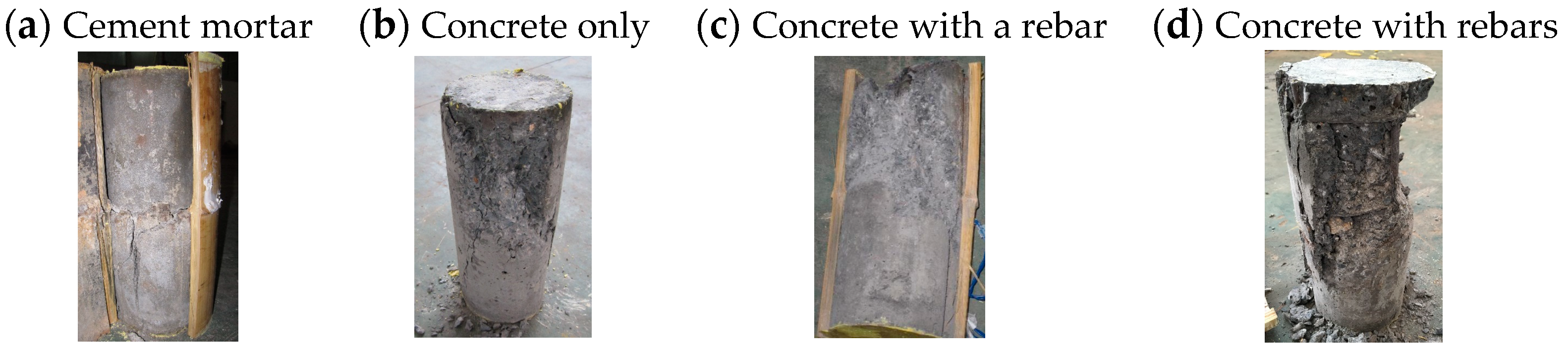
Overall Observations and Failure Modes

The stiffness and ultimate bearing capacity of BFC members were significantly higher than those of conventional bamboo structures with the same parameters. Typical morphologies of BFC members during loading are in Figure 5. Before reaching the ultimate load capacity, no visible cracks formed (Figure 6a). As the peak load was approached, fine longitudinal cracks and slight tube bulging occurred. At the peak load, local cracks expanded into at least one obvious through-crack (Figure 6b) due to insufficient transverse bamboo capacity. Subsequently, the crack widths and numbers rapidly increased due to crushed filler, resulting in force transfer to the bamboo and compressive cracking. Each crack indicated a drop in capacity. When there were 3–5 wide through-cracks, capacity dropped to a value similar to that of hollow bamboo, resulting in failure (Figure 6c).
Hollow bamboo members showed two failure modes (Figure 7). In the absence of stiffeners (Figure 7a), through-cracks and some un-through cracks formed; some cracks stopped at bamboo nodes. With stiffeners (Figure 7b), all cracks stopped near stiffeners; local buckling occurred at the end. Stiffeners influenced the failure modes, aligning with the findings of Li, Long et al. [22], in which nodes and stiffeners hindered crack propagation in bamboo.
The failure modes of filled members are listed in Figure 8. In Figure 8a, a nearly conical through-diagonal crack failure is observed for the concrete filler, indicating its full utilization and minimal influence from nodes/horizontal stiffeners. Figure 8b exhibits the failure of a crushed mortar filler with a nearly conical shape, which also suggests its full utilization. It is worth noting that the crushing of mortar was distinctly concentrated at the node, caused by diaphragms that created weakened areas where crack initiation occurred; thus, the failure was more prominent. Furthermore, the arrangements of reinforcements were compared. In Figure 8c, a nearly conical failure is observed for concrete with a central C12 bar arrangement, resembling that of unreinforced concrete. Figure 8d illustrates a significantly distinctive failure for concrete with a cage composed of 4 C 6 bars and A 4 stirrups spaced at 50 mm intervals. The failure manifested as diagonal cracks extending towards the cage edges, accompanied by the spalling of the surrounding concrete and exposure of the reinforcement bars.

3.2. Ultimate Capacity and Peak Strain

The ultimate strength N u - EXP , peak strain ε cc - EXP , and load–strain curves demonstrate that bamboo supports the axial load and constrained the expansion of the filler material in a manner similar to a steel tube used in concrete-filled steel tube columns.
Table 3 and Figure 9 illustrate that the axial strengths of BFC members are significantly higher than bamboo, with strength ratios N u - EXP / N u - EXPb ranging from 2.71 to 5.39 times that of hollow bamboo, attributed to the presence of compressive filler. Specimens filled with mortar exhibited lower average cross-sectional strength f a compared to hollow bamboo, while specimens filled with concrete generally demonstrated higher strengths f a due to the higher strength of concrete in comparison to bamboo. To enhance the average compressive strength, the compressive filler material should possess a higher strength than bamboo.
As shown, bamboo supported the axial load and constrained the expansion of the filler material in a manner similar to a steel tube used in concrete-filled steel tube columns.
As shown in Table 3, hollow bamboo exhibited the highest peak strain among all of the BFC specimens. Specimens filled with plain concrete or mortar demonstrated significantly lower peak strain compared to hollow bamboo but higher than plain concrete or mortar alone, indicating a significant interaction and constraint between the bamboo and the concrete/mortar filler, thereby improving deformation performance. Bamboo supported the axial load and constrained the expansion of the filler material in a manner similar to a steel tube used in concrete-filled steel tube columns.

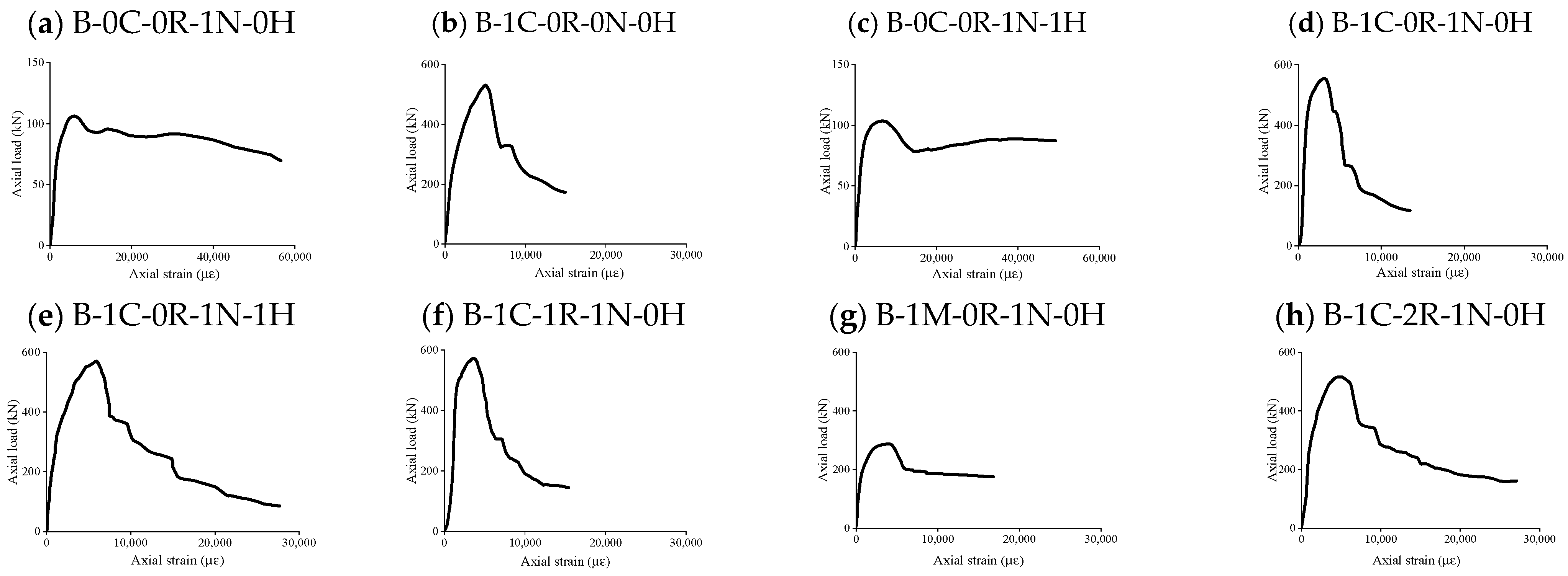
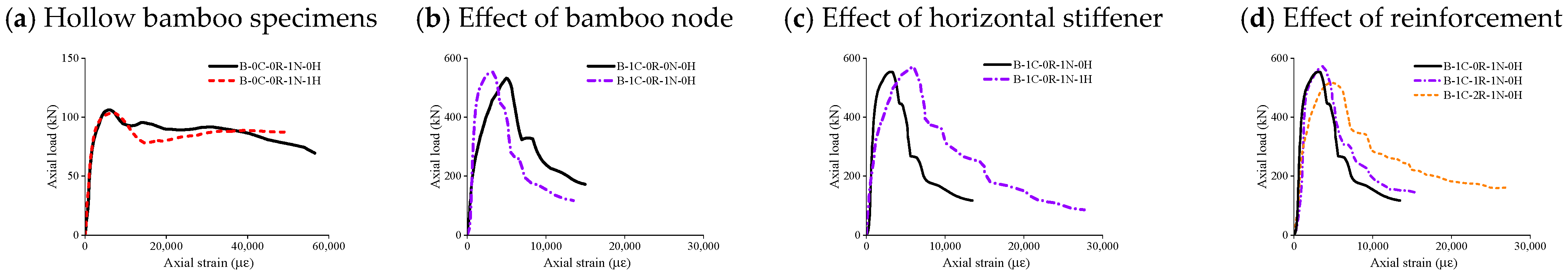
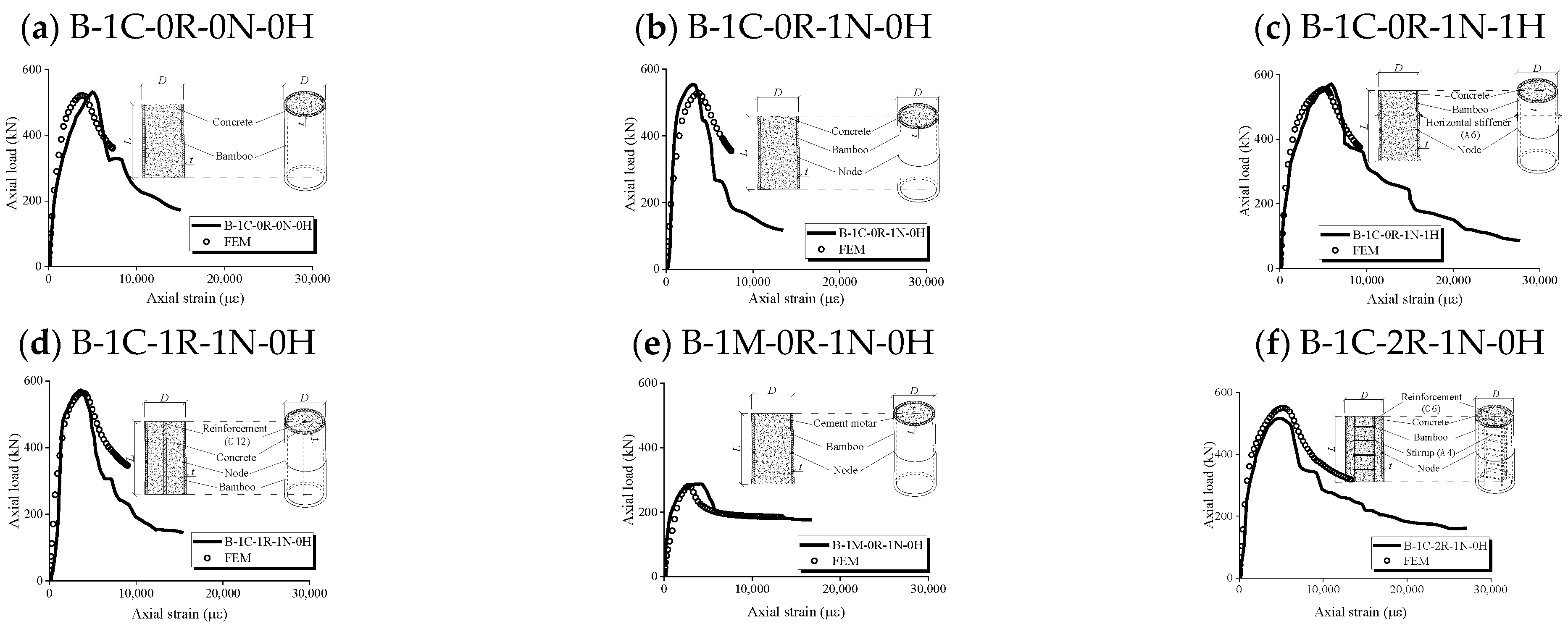
3.3. Axial Load–Strain Behavior

3.3.1. Hollow Bamboo Specimens

As shown in Figure 10a, the load–strain curves of the two hollow specimens initially rose similarly but diverge significantly after the peak points. According to Table 3 and Table 4, specimen B-0C-0R-1N-1H had 93.7% of B-0C-0R-1N-0H’s cross-sectional area but its peak load is 102.4% of the latter, indicating that the presence of holes in the bamboo tube wall decreases the load-bearing capacity. The peak strain of B-0C-0R-1N-1H was higher compared to B-0C-0R-1N-0H. After a slight drop in capacity, B-0C-0R-1N-1H exhibits a further drop in load with increasing deformation, attributed to the hindrance of longitudinal crack propagation by horizontal stiffeners and bamboo nodes. In contrast, B-0C-0R-1N-0H shows minor fluctuations in capacity with deformation but overall decreases after reaching the peak due to the absence of horizontal stiffeners hindering longitudinal crack growth by bamboo nodes.

3.3.2. Solid BFC Specimens

Unlike hollow specimens, the axial load–strain curves of solid specimens generally exhibit multiple stages of increasing strain, which suggests that internal microcracks initiate and propagate prematurely due to axial compression and filler compression, resulting in the formation of cracks and a reduction in axial stiffness. This reduction in stiffness is abrupt and more pronounced at peak loads on the ascending curve (Figure 9), which is consistent with the presence of “fine longitudinal cracks at peak loads” discussed in Section 3.1. After the peak loads, the descending of all solid specimens exhibited multiple abrupt drops, indicating a significant decrease in stiffness that occurred in multiple abrupt changes. This observation aligns with the findings in Section 3.1, where it was reported that the propagation of multiple longitudinal cracks led to these pronounced drops.
To analyze the parameters of the solid specimens, they were divided into key components, including bamboo joints, transverse stiffening ribs, filler material, and rebar. Notably, specimens with a bamboo node exhibited a slightly higher ultimate bearing capacity, which is consistent with the findings of Li, Long et al. [22], as shown in Figure 10b. Furthermore, Figure 10c demonstrates that bamboo supported the axial load and constrained the expansion of the filler material in a manner similar to a steel tube used in concrete-filled steel tube columns and Table 4 demonstrates that the presence of horizontal stiffeners significantly improves the ductility of the specimens. The ductility coefficient of specimen B-1C-0R-1N-1H was nearly twice that of B-1C-0R-1N-0H. Additionally, while drilling holes near bamboo nodes had an adverse effect on the bearing capacity of hollow specimens, this effect was insignificant in solid specimens. Specimen B-1C-0R-1N-1H retained 97.1% of the cross-sectional area and 96.9% of the bearing capacity of B-1C-0R-1N-0H. Therefore, the impact of horizontal stiffeners on solid specimens was found to be negligible.
As depicted in Figure 10d, bamboo supported the axial load and constrained the expansion of the filler material in a manner similar to a steel tube used in concrete-filled steel tube columns. As shown in Table 4, the addition of a single rebar had a minor impact on the load–strain curves of solid specimens. The slight increase in bearing capacity and peak strain was attributed to the partial replacement of concrete filler with a higher-strength and better-deformability rebar. In comparison, when using a rebar cage with the same cross-sectional area as the single rebar, the arrangement of the rebar cage significantly enhanced ductility. Specifically, in specimen B-1C-2R-1N-0H, the peak strain ε cc and ductility coefficient μ were significantly higher than those of B-1C-0R-1N-0H and B-1C-1R-1N-0H.
Additionally, the results from Table 3 and Table 4 revealed that B-1C-2R-1N-0H exhibited 90.2% of B-1C-1R-1N-0H’s cross-sectional area and ultimate bearing capacity. Thus, the lowest ultimate bearing capacity observed in Figure 10d for B-1C-2R-1N-0H can be attributed to its smallest cross-sectional area, rather than the presence of the rebar cage.
Based on the experimental observations and the axial load–axial strain curves of the specimens above, the interaction between the concrete and the bamboo tube under axial loading is as follows: In the elastic phase, both the bamboo tube and concrete share the axial load. The confinement effect of the bamboo tube on the lateral expansion of the concrete is negligible. As the axial load increases, the expansion of the concrete intensifies. The confinement effect of the bamboo tube becomes significant and gradually reaches its peak. This process delays the premature cracking of the concrete. With further expansion, the bamboo tube eventually ruptures. This leads to a steep decline in the confinement effect and a corresponding significant drop in load-bearing capacity.

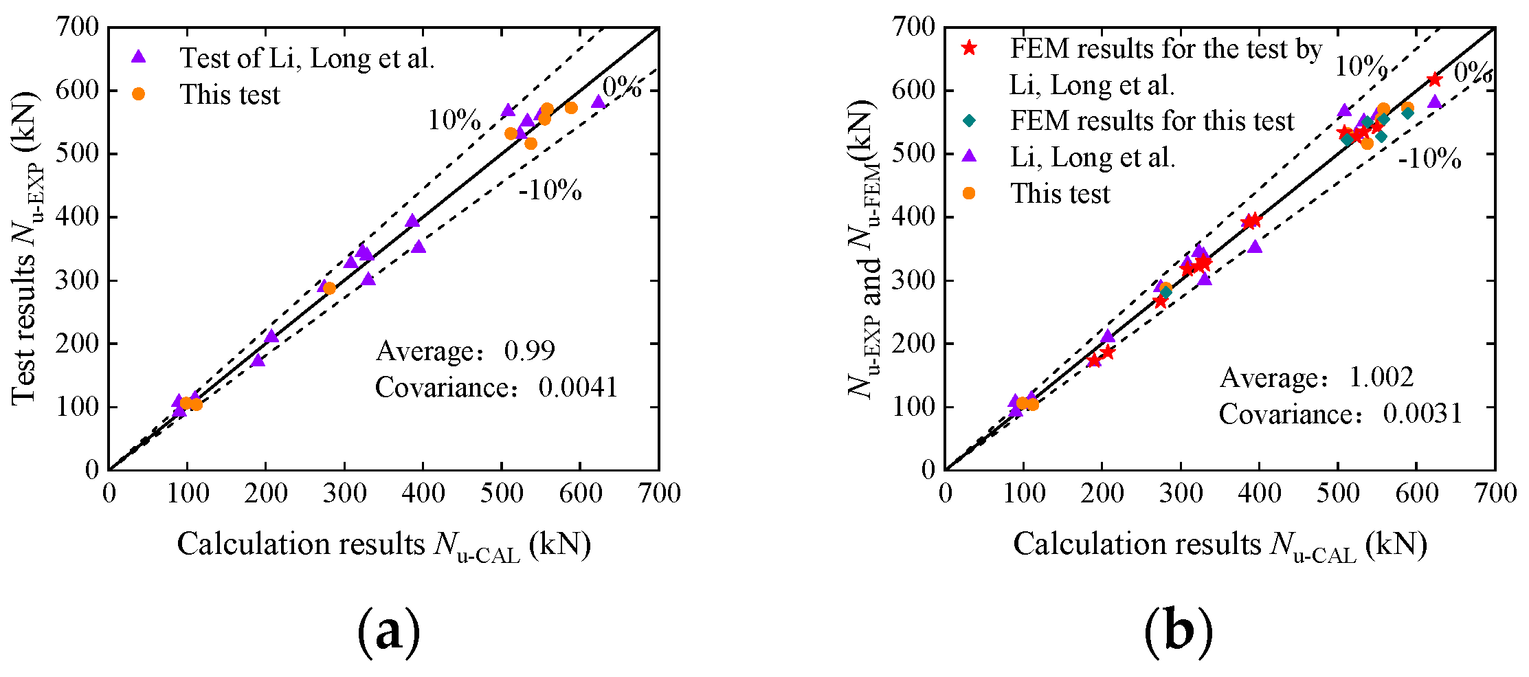
3.4. Model Validation

The solid BFC specimens were utilized in this test to validate the finite element model. The comparison of the axial load–strain curves is presented in Figure 11. It should be noted that bamboo tubes, being non-industrial products, possess mechanical properties that are influenced by natural growth conditions and hence may exhibit certain variations, which deviates from the idealized finite element model that neglects defects. However, the rising segments of all of the finite element model curves, as well as the peak points, exhibit similarities to the experimental curves. Although the descending segments of the simulation curves do not accurately depict the stepwise drop characteristics, their overall descending trends align well with the experimental curves.
Comparisons with the tests conducted by Li, Long et al. [22] provided additional validation for the finite element models (FEMs), as depicted in Figure 12. The similar trends observed between the simulation and experimental results affirm the accuracy of the FEMs. The ratios of the simulated bearing capacity and strain to the experimental values had averages of 0.99 and 0.976, respectively, with variances of 0.003 and 0.009 (as shown in Figure 13). These findings indicate that the FEMs exhibit acceptable levels of accuracy and precision.

4. Discussion

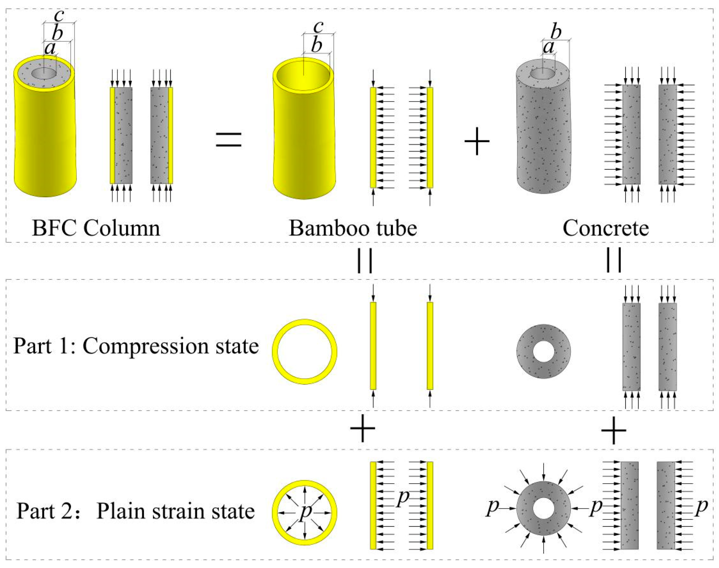
4.1. Mathematical Model of BFC Columns

Due to the similarity between the axial compression stress mechanism of BFC members and concrete-filled steel tube columns, the load-bearing capacity of BFC members was deduced using the axial compression mechanical model of a concrete-filled steel tube. This deduction was also supported by the experimental study conducted by Li, Long et al. [22], which revealed the significant confinement effect of bamboo tubes on 4concrete. The elastic analysis of concrete-filled steel tube columns by Yu et al. [34] was referenced to consider the axial compression of BFC short columns as a superposition of uniaxial compression problems of bamboo tubes and concrete, along with plane strain problems. The cross-sectional dimensions and stress decomposition of BFC components in the elastic state are presented in Figure 14.
Assume the average axial compressive strain of the BFC element during the elastic phase is ε z cb , in accordance with the axial strain coordination between concrete and bamboo culms:
ε z c = ε z b = ε z cb
Step 1: Compression state: Assume concrete is isotropic. The mechanical properties of bamboo tube walls change linearly with the wall thickness [35,36]. To simplify the theoretical derivation under the approximate premise, assume the bamboo tube is transversely isotropic, i.e., isotropic in its cross-section. According to the generalized Hooke’s law, the formula is as follows:
ε r b = ε θ b = ν zr ε z cb
ε r c = ν c ε z cb
The axial stresses of bamboo tubes σ b 1 and concrete σ c 1 are as follows:
σ b 1 = ε z cb E zb σ c 1 = ε z cb E c
Based on Equations (14) and (15), the radial displacements of the inner wall of bamboo tubes u b 1 and the outer wall of concrete u c 1 are, respectively, as follows:
u b 1 = b ε r b = b ν zr ε z cb u c 1 = b ε r c = b ν c ε z cb
Step 2: Plain strain state: Given the analytical solution of a thick-walled cylinder [37], the axial stress of a concrete cylinder under the uniform circumferential pressure p is as follows:
σ c 2 = 2 ν c ( b 2 a 2 ) ( b 2 p )
Bamboo tubes are not isotropic, so the thick-walled cylinder theory cannot be directly applied. In order to derive expressions for the axial stress σ b 2 of bamboo tubes subjected to uniform circumferential pressure p on the inner wall, an elastic model needs to be established for the plane strain state of a transversely isotropic cylindrical tube. Considering the characteristics of the plane strain state and its symmetry, the constitutive equation for a transversely isotropic cylindrical tube is given by the following:
{ ε θ = 1 E θ ( σ θ ( 1 ν θ z ν z θ ) σ r ( ν θ r + ν θ z ν z θ ) ) ε r = 1 E θ ( σ r ( 1 ν θ z ν z θ ) σ θ ( ν θ r + ν θ z ν z θ ) ) ε z = 0
{ σ θ = E θ ε θ ( 1 ν θ z ν z θ ) + E θ ε r ( ν θ r + ν θ z ν z θ ) ( 1 ν θ r 2 ν θ z ν z θ ) ( 1 + ν θ r ) σ r = E θ ε r ( 1 ν θ z ν z θ ) + E θ ε θ ( ν θ r + ν θ z ν z θ ) ( 1 ν θ r 2 ν θ z ν z θ ) ( 1 + ν θ r ) σ z = ν z θ ( σ θ + σ r )
{ σ r = b 2 c 2 ( p 2 p 1 ) c 2 b 2 1 r 2 + b 2 p 1 c 2 p 2 c 2 b 2 σ θ = b 2 c 2 ( p 2 p 1 ) c 2 b 2 1 r 2 + b 2 p 1 c 2 p 2 c 2 b 2
Because there is no relationship between the classical Lamé formula (see Equation (21)) and elastic constants, it is still applicable in the transversely isotropic cylindrical bodies.
Thus, the axial stress σ b 2 of bamboo in the plain strain state when the circumferential pressure on the inner wall of the bamboo tube is p can be calculated using Equations (20) and (21), as follows:
σ b 2 = 2 b 2 p c 2 b 2 ν z θ
Owing to the balance of forces, A cb σ cb = A c ( σ c 1 + σ c 2 ) + A b ( σ b 1 + σ b 2 ) . Thus,
σ cb = b 2 a 2 c 2 a 2 [ ε z cb E c 2 b 2 ν c ( b 2 a 2 ) p ] + c 2 b 2 c 2 a 2 ( ε z cb E zb + 2 b 2 ν z θ c 2 b 2 p )
Since the expression of Equation (23) is complicated, referring to the method of introducing intermediate variables by Yu Min et al. [34], let a , b , and c be represented by the intermediate variables β , Ω , and ξ bc , where β = c 2 b 2 c 2 a 2 represents the ratio of the cross-sectional area of the bamboo tube to the total cross-sectional area; Ω = b 2 a 2 b 2 represents the solid ratio of concrete; and ξ bc = c 2 b 2 b 2 σ b θ σ c represents the solid hoop coefficient of bamboo. Thus, Equation (23) is simplified as follows:
σ cb = ( 1 β ) [ σ c + 2 p ( ν z θ ν c ) Ω ] + β σ bz
where σ c and σ bz are the axial stress of concrete and bamboo in elastic, respectively. σ c = ε z cb E c , σ bz = ε z cb E zb . The definitions of all parameters mentioned above can be found in the Nomenclature.

4.2. Formula of the Ultimate Bearing Capacity of BFC Columns

When the axial stress of concrete and the axial and hoop stresses of bamboo reach the yield limit, i.e., when σ c = f co and σ bz = f bz , and referencing the coefficient of the enhanced confinement effect η proposed by Li et al. [37], Equation (24) is rewritten as follows:
f cb = ( 1 β ) ( 1 + η ) f co + β f bz
η = 2 p ( ν z θ ν c ) Ω f co
It is noteworthy that p in Equation (26) is unknown. Since the confinement effect of bamboo tubes on concrete is similar to that of steel tubes on concrete in concrete-filled steel tube members, the formula for the coefficient of the enhanced confinement effect η proposed by Li et al. [9] is as follows:
η = 1 A + B f co f yt + C ξ sc
where f yt is the ultimate hoop strength of the steel tube; ξ sc = c 2 b 2 b 2 f yt f co represents the solid hoop coefficient of steel; and A, B, and C represent unknown constants related to the Poisson’s ratios of the concrete and steel tube. Therefore, according to Equation (27), it can be translated into a formula applicable to BFC members:
η = 1 A + B f co f b θ + C ξ bc
where f b θ is the ultimate hoop strength of the bamboo tube; ξ bc represents the solid hoop coefficient of bamboo; and A, B, and C represent unknown constants related to the Poisson’s ratios of concrete and bamboo tubes.
Several tested BFC members in this paper contain steel bars, thus the load-bearing capacity of the steel bars needs to be included in the bearing capacity of the members. Therefore, the axial load-bearing capacity of BFC members is calculated as follows:
N u - CAL = A cb f cb + A s f y
Regression analysis was performed on the constant values of A, B, and C by the test data obtained in this study. After multiple comparisons and meticulous selection, the constant values of A, B, and C were determined to be A = 0.05 , B = 3 , and C = 9.2 . These constant values take into account initial imperfections within the members, cross-sectional flaws as well as unusual loading conditions, to a certain degree. The mean and variance of the ratios between the calculated results and the test results were 0.99 and 0.002, respectively, indicating a close agreement between the calculated and experimental results.
To further validate the accuracy of the formula, the test results from Li, Long et al. [22] were also included in the comparison with the calculated results of the formula, as shown in Figure 15a. The ratio of the calculated values to the test values has a mean of 0.99 and a variance of 0.0041, indicating good agreement between the formula calculations and the test results. Additionally, the calculated values were compared with the results from this test, the test by Li, Long et al. [22], and the corresponding FEM results, as shown in Figure 15b. The ratio of the calculated values to the test values/FEM results has a mean of 1.002 and a variance of 0.0031. These results demonstrate the applicability of the formula for calculating BFC columns.

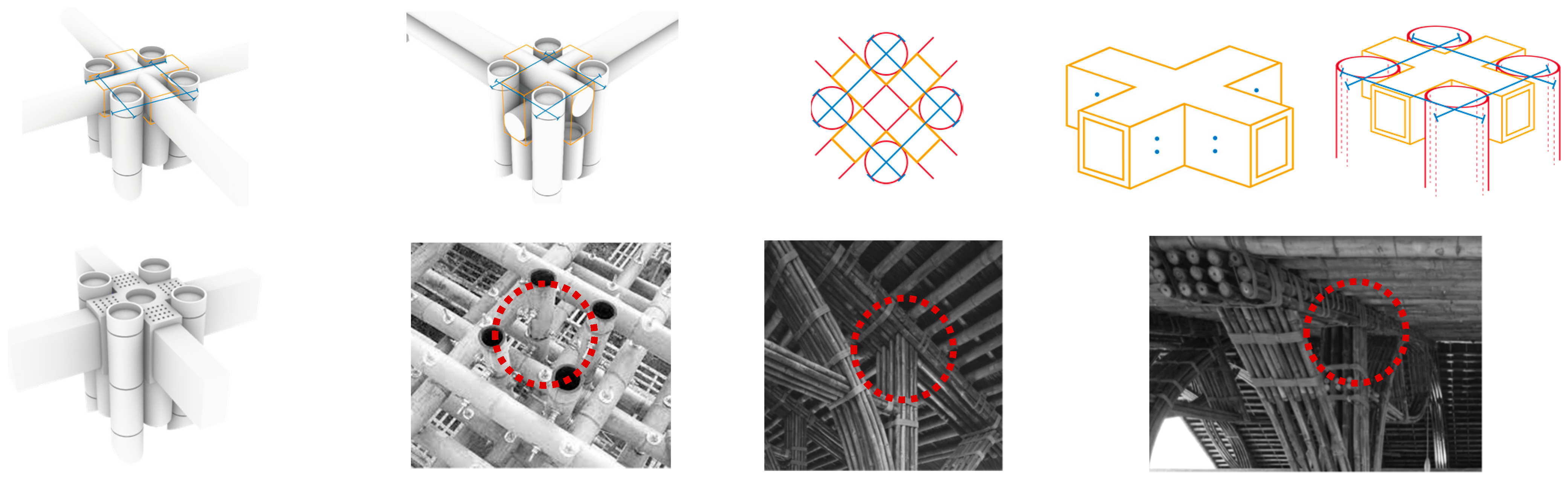
4.3. Impact of BFC on Bamboo Architecture

It is clear from the aforementioned data that BFC expands the range of options available for building construction. As illustrated in Figure 16, the performance of bamboo buildings is improved, and the sustainable development of the ecological environment is encouraged, by injecting concrete or cement mortar into the bamboo columns that must withstand compression and then using bamboo materials as the tensile reinforcement. Additionally, there are many other design options for bamboo buildings due to their higher compressive capacity, which increases the range of building forms available.

Analysis of the Program’s Viability

A cross box-style thin wall connecting part made of mild steel opens the end of a single column. Four long pieces of bamboo are positioned parallel to each other, configured with longitudinal and transversal bi-directional tie rods that simultaneously penetrate the beam and column, and fastened in place. Values up to 15,831 N were obtained from estimates of the single column end’s ultimate bearing capacity; see Table S1 in the Supplementary Material for details of the calculation process. It is evident that the bearing capacity of BFC is much higher than the bearing capacity of a single bamboo column end in the absence of concrete material injection. It is evident from this that the study has significance in real-world applications. For instance, Figure 17 illustrates how enhancing the column ends of bamboo buildings can improve their performance strength, lengthen their service life, fulfill the goal of resource conservation, safeguard the environment, and encourage the economy’s sustainable development.
To actualize various construction methods, various forms of bamboo structures are evaluated and studied based on the final bearing capability of a single column end. Analyzing the single beam in Figure 18 reveals that its force strength is rather low and essentially manifests as a straightforward design.
In order to better understand and research the construction of double- and triple-layer beams, an analysis of single-beam construction was conducted, see Figure 19. The results showed that the following: (1) Double-layer beam construction is more complex than single-beam construction, but the architectural form is still relatively rich. It is determined that there are a total of eleven bolts in the double-layer beam structure, three constructive bolts, and eight shear connectors. (2) The construction of three-layer beams is again relatively complex compared to the construction of double-layer beams, and the architectural form tends to be more exquisite, and the service life is also extended. The total number of bolts in the construction of the three-layer beam is thirty-three, and the number of construction bolts is seventeen; the number of shear connectors is also eight.
It was found that with the construction of double and triple beams, the bolts at the top of the beams should have a gap of 5 CM and the bolts should be spaced at an appropriate distance of 10 CM. Therefore, the modulus construction can be strengthened to simplify the process, which reduces the construction period and enhances the efficiency of the bamboo structure construction, which has universal application value.

5. Conclusions

This paper presents a supplementary experimental study on the axial load behaviors of BFC members. A total of eight specimens were tested under axial compression, and the failure modes of axial compression were further analyzed. The paper also discusses in detail the effects of bamboo nodes, filling materials, horizontal stiffeners, and steel bars on the mechanical properties of specimens with hollow bamboo tubes and bamboo tubes filled with materials. The constitutive relationships of bamboo tubes, confined concrete, and confined mortar in bamboo tubes were established, along with finite element models of BFC members. The accuracy of the finite element models was verified using test data. Additionally, a new method for calculating the axial compression-bearing capacity of BFC members is proposed. The following conclusions have been drawn:
(1) External observation revealed multiple vertical cracks in the bamboo tubes as clear signs of failure. Internally, obvious inclined cracks appeared in the filling materials as the specimens failed. In specimens with steel bar cages, the inclined cracks in the filling materials were blocked by the steel bar cages and did not propagate through.
(2) Bamboo nodes and horizontal stiffeners had a slightly beneficial effect on the ultimate bearing capacity, while steel bar cages and horizontal stiffeners significantly improved the ductility of the members.
(3) The proposed BFC member modeling method with the constitutive relationships of bamboo tubes, confined concrete, and confined mortar, accurately predicts the rising section law of the axial stress–strain curve, the ultimate bearing capacity, and the corresponding strain of the members. The overall trend prediction of the descending section is similar.
(4) An elastic model of a transversely isotropic circular cylinder was established. By combining this model with the model of an isotropic thick-walled cylinder, a new method for calculating the axial capacity under the axial compression of BFC members was obtained. The proposed calculation method for the bearing capacity of BFC members was then derived through regression analysis and further verification of the test data.
(5) The proposed method accounts for initial imperfections within the members, cross-sectional flaws, and atypical loading conditions. It can effectively predict the ultimate bearing capacities of BFC stub columns, yielding close agreement between the calculated and experimental results.
(6) When using BFC components at joints, it is recommended to include infilled concrete, steel bar cages, and transverse stiffeners to enhance the load-bearing capacity and ductility, ensuring joint failure occurs later than other parts. The concrete infill should be sufficiently long to ensure effective collaboration between the concrete, transverse stiffeners, and bamboo tubes.
(7) BFC and its different construction methods play an important role in the construction and morphological design of bamboo buildings. By improving the performance of the bamboo structure, diversifying the building form, and optimizing the construction process of bamboo buildings, it prolongs the service life of the building, promotes the sustainable development of the ecological environment and the economy, and improves the overall benefits of bamboo buildings; therefore, it has universal application value and research significance.

Supplementary Materials

The following supporting information can be downloaded at: https://www.mdpi.com/article/10.3390/buildings14072029/s1, Table S1: The maximum bearing capacity of a single column end.

Author Contributions

Conceptualization, J.H. and Y.L.; methodology, J.H.; software, W.L.; validation, Y.L., X.L. and J.H.; formal analysis, X.L.; investigation, X.L.; resources, J.H.; data curation, Y.L., X.L; writing—original draft preparation, X.L., R.W.; writing—review and editing, J.H.; visualization, J.H.; supervision, J.H.; project administration, J.H.; funding acquisition, J.H. All authors have read and agreed to the published version of the manuscript.

Funding

This study is funded by the Guangdong Research Institute of China Engineering Science and Technology Development Strategy Consulting Research Program (Grant No. 2022-GD-11).

Data Availability Statement

The original contributions presented in the study are included in the article, further inquiries can be directed to the corresponding author.

Conflicts of Interest

The authors declare no conflicts of interest.

Appendix A

The specific design suggestions and steps of BFC can be expressed as follows:
(1) Bamboo Selection and Pretreatment: The bamboo culms used in the structures were carefully selected, each measuring 6 m in length and 5 years in age, to ensure the accuracy of the specimen dimensions. All bamboo culms were air-dried for 3 months to ensure that the moisture content was less than 15%.
(2) Processing and Fabrication: Cut the bamboo tubes to the designed dimensions and remove the internal bamboo node diaphragms. Pre-drill holes at the locations for the transverse stiffeners on the bamboo tubes. Insert the steel bar cages and transverse stiffeners into the bamboo tubes. Pour concrete into the bamboo tubes and begin curing. Clean the surface of the bamboo tubes soon after the concrete has been poured.
(3) The axial capacity calculation of BFC is as follows:
N u - CAL = A cb f cb + A s f y
The compressive strength of the confined concrete f cb is calculated as follows:
f cb = ( 1 β ) ( 1 + η ) f co + β f bz
in which the enhanced confinement effect η can be calculate as below:
η = 1 0.05 + 3 f co f b θ + 9.2 ξ bc
ξ sc = t 2 ( D 2 t ) 2 f b θ f co

References

  1. Escamilla, E.Z.; Habert, G.; Daza, J.F.C.; Archilla, H.F.; Fernández, J.S.E.; Trujillo, D. Industrial or traditional bamboo construction? Comparative life cycle assessment (LCA) of bamboo-based buildings. Sustainability 2018, 10, 3096. [Google Scholar] [CrossRef]
  2. Lou, Z.; Wang, Q.; Sun, W.; Zhao, Y.; Wang, X.; Liu, X.; Li, Y. Bamboo flattening technique: A literature and patent review. Eur. J. Wood Prod. 2021, 79, 1035–1048. [Google Scholar] [CrossRef]
  3. Lou, Z.; Yuan, T.; Wang, Q.; Wu, X.; Hu, S.; Hao, X.; Liu, X.; Li, Y. Fabrication of crack-free flattened bamboo and its macro-/micro morphological and mechanical properties. J. Renew. Mater. 2021, 9, 959–977. [Google Scholar] [CrossRef]
  4. Lou, Z.; Han, X.; Liu, J.; Ma, Q.; Yan, H.; Yuan, C.; Yang, L.; Han, H.; Weng, F.; Li, Y. Nano-Fe3O4/bamboo bundles/phenolic resinoriented recombination ternary composite with enhanced multiple functions. Compos Pt. B Eng. 2021, 226, 109335. [Google Scholar] [CrossRef]
  5. Lou, Z.; Wang, Q.; Kara, U.I.; Mamtani, R.S.; Zhou, X.; Bian, H.; Yang, Z.; Li, Y.; Lv, H.; Adera, S.; et al. Biomass-derived carbon heterostructures enable environmentally adaptive wideband electromagnetic wave absorbers. Nano-Micro Lett. 2022, 4, 11. [Google Scholar] [CrossRef] [PubMed]
  6. Chen, C.; Li, Z.; Mi, R.; Dai, J.; Xie, H.; Pei, Y.; Li, J.; Qiao, H.; Tang, H.; Yang, B.; et al. Rapid processing of whole bamboo with exposed, aligned nanofibrils toward a high-performance structural material. ACS Nano 2020, 14, 5194–5202. [Google Scholar] [CrossRef] [PubMed]
  7. Sanchez, C.H.; Arribart, M.G.; Guile, M.G. Biomimetism and bioinspiration as tools for the design of innovative materials and systems. Nat. Mater. 2005, 4, 277–288. [Google Scholar] [CrossRef] [PubMed]
  8. Zhang, Y. Mechanical characteristics of tensile strength for three monopodial bamboo single roots. Sci. Silvae Sin. 2013, 49, 183–187. [Google Scholar] [CrossRef]
  9. Li, Z.; Chen, C.; Mi, R.; Gan, W.; Dai, J.; Jiao, M.; Xie, H.; Yao, Y.; Xiao, S.; Hu, L. A strong, tough, and scalable structural material from fast-rowing bamboo. Adv. Mater. 2020, 32, 1906308. [Google Scholar] [CrossRef]
  10. Lu, K. The future of metals. Science 2020, 328, 319–320. [Google Scholar] [CrossRef] [PubMed]
  11. Bouville, F.; Maire, E.; Meille, S.; Van de Moortèle, B.; Stevenson, A.J.; Deville, S. Strong, tough and stiff bioinspired ceramics from brittle constituents. Nat. Mater. 2014, 13, 508–514. [Google Scholar] [CrossRef]
  12. Song, J.; Chen, C.; Zhu, S.; Zhu, M.; Dai, J.; Ray, U.; Li, Y.; Kuang, Y.; Li, Y.; Quispe, N.; et al. Processing bulk natural wood into a high-performance structural material. Nature 2018, 554, 224–228. [Google Scholar] [CrossRef] [PubMed]
  13. Mittal, N.; Ansari, F.; Gowda, V.K.; Brouzet, C.; Chen, P.; Larsson, P.T.; Roth, S.; Lundell, F.; Wågberg, L.; Kotov, N.A.; et al. Multiscale control of nanocellulose assembly: Transferring remarkable nanoscale fibril mechanics to macroscale fibers. Acs Nano 2018, 12, 6378–6388. [Google Scholar] [CrossRef] [PubMed]
  14. Xia, M.; Sanjayan, J. Method of formulating geopolymer for 3d printing for construction applications. Mater. Des. 2016, 110, 382–390. [Google Scholar] [CrossRef]
  15. Wegst, U.G.; Bai, H.; Saiz, E.; Tomsia, A.P.; Ritchie, R.O. Bioinspired structural materials. Nat. Mater. 2015, 14, 23–26. [Google Scholar] [CrossRef] [PubMed]
  16. Wang, Y.Y.; Wang, X.Q.; Li, Y.Q.; Huang, P.; Yang, B.; Hu, N.; Fu, S.Y. High-performance bamboo steel derived from natural bamboo. ACS Appl. Mater. Interfaces 2021, 13, 1431–1440. [Google Scholar] [CrossRef] [PubMed]
  17. Yang, Y.K. Strengthening and toughening of a 2800-MPa grade maraging steel. Mater. Lett. 2020, 56, 763–769. [Google Scholar] [CrossRef]
  18. Sun, Q.F. Inspiration given by nature: A brief discussion on wood bionics. China Chem. Eng. Sci. 2014, 16, 4–12+2. [Google Scholar]
  19. Sun, J.; Wang, W.; Song, Y. Tectonic Finish Control. New Archit. 2021, 34–37. [Google Scholar]
  20. Bala, A.; Gupta, S. Engineered bamboo and bamboo-reinforced concrete elements as sustainable building materials: A review. Constr. Build. Mater. 2023, 394, 132116. [Google Scholar] [CrossRef]
  21. Zhao, Y.; Huang, Y.; Gao, X. A Study on the Design Methods and Technical Strategies of Bamboo Architecture by Wu Chongyi. Archit. J. 2024, 70–77. [Google Scholar] [CrossRef]
  22. Li, W.T.; Long, Y.L.; Huang, J.; Lin, Y. Axial load behavior of structural bamboo filled with concrete and cement mortar. Constr. Build. Mater. 2017, 148, 273–287. [Google Scholar] [CrossRef]
  23. Yu, T.; Teng, J.G.; Wong, Y.L.; Dong, S.L. Finite element modeling of confined concrete-II: Plastic-damage model. Eng. Struct. 2010, 32, 680–691. [Google Scholar] [CrossRef]
  24. Teng, J.G.; Xiao, Q.G.; Yu, T.; Lam, L. Three-dimensional finite element analysis of reinforced concrete columns with FRP and/or steel confinement. Eng. Struct. 2015, 97, 15–28. [Google Scholar] [CrossRef]
  25. GB 50010-2010; Code for Design of Concrete Structures. China Architecture and Building Press: Beijing, China, 2010.
  26. Candappa, D.C.; Sanjayan, J.G.; Setunge, S. Complete triaxial stress-strain curves of high-strength concrete. J. Mater. Civ. Eng. 2001, 13, 209–215. [Google Scholar] [CrossRef]
  27. Wang, Y.; Yang, L.; Yang, H.; Liu, C. Behaviour of concrete-filled corrugated steel tubes under axial compression. Eng. Struct. 2019, 183, 475–495. [Google Scholar] [CrossRef]
  28. Yuan, S. The Research on The Constitutive Model and Size Effect Law of Masonry Mortar; Changsha University of Science Technology: Changsha, China, 2019. [Google Scholar]
  29. Liu, J.P.; Zhou, X.H.; Gan, D. Effect of friction on axially loaded stub circular tubed columns. Adv. Struct. Eng. 2016, 19, 546–559. [Google Scholar] [CrossRef]
  30. Tao, Z.; Wang, Z.B.; Yu, Q. Finite element modelling of concrete-filled steel stub columns under axial compression. J. Constr. Steel Res. 2013, 89, 121–131. [Google Scholar] [CrossRef]
  31. Tang, M.; Yi, W.J.; Chen, H.; Wu, Y.F. Numerical and analytical investigation on the moment and deformation capacity of interior slab-column connections without shear reinforcement. Adv. Struct. Eng. 2021, 24, 3707–3723. [Google Scholar] [CrossRef]
  32. Lawson, R.M.; Ogden, R.G.; Bergin, R. Application of modular construction in highrise buildings. J. Archit. Eng. 2012, 18, 148–154. [Google Scholar] [CrossRef]
  33. Lima, H.C.; Willrich, F.L.; Barbosa, N.P.; Rosa, M.A.; Cunha, B.S. Durability analysis of bamboo as concrete reinforcement. Mater. Struct. 2008, 41, 981–989. [Google Scholar] [CrossRef]
  34. Yu, M.; Zha, X.X.; Ye, J.Q.; She, C.Y. A unified formulation for hollow and solid concrete-filled steel tube columns under axial compression. Eng. Struct. 2010, 32, 1046–1053. [Google Scholar] [CrossRef]
  35. Vaessen, M.J.; Janssen, J.J.A. Analysis of the critical length of culms of bamboo in four-point bending tests. Heron 1997, 42, 113–124. [Google Scholar]
  36. Sadd, M.H. Elasticity: Theory, Applications and Numerics; Academic Press: Cambridge, MA, USA, 2014. [Google Scholar]
  37. Li, W.; Zha, X.; Wang, H. A unified formulation for axial compression of steel tube-confined concrete and concrete-filled steel tube stub columns. Structures 2023, 58, 105319. [Google Scholar] [CrossRef]
Figure 1. Design of test specimens.
Buildings 14 02029 g001
Figure 2. Size of bamboo strip specimens.
Buildings 14 02029 g002
Figure 3. Stress–strain curves of longitudinal and circumferential tensile test.
Buildings 14 02029 g003
Figure 4. Transverse tensile test on bamboo ring.
Buildings 14 02029 g004
Figure 5. Test setup and instrumentation layout.
Buildings 14 02029 g005
Figure 6. Typical modes of the specimen during loading.
Buildings 14 02029 g006
Figure 7. Failure mode of hollow bamboo tube specimens.
Buildings 14 02029 g007
Figure 8. Failure mode of infilled materials.
Buildings 14 02029 g008
Figure 9. Axial load–strain curves of specimens.
Buildings 14 02029 g009
Figure 10. Comparison of axial load–axial strain curves under the influence of different parameters.
Buildings 14 02029 g010
Figure 11. Comparison of finite element and experimental axial load–axial strain curves.
Buildings 14 02029 g011
Figure 12. Comparison of FEM and experimental axial load–axial strain curves of solid BFC specimens.
Buildings 14 02029 g012
Figure 13. Comparison of peak load and strain at peak load between test and FEM. (a) Comparison of peak load [22]; (b) Comparison of strain at peak load [22].
Buildings 14 02029 g013
Figure 14. Elastic analysis of BFC stub columns.
Buildings 14 02029 g014
Figure 15. Comparison of the calculation results with test results and FEM results. (a) Comparison of the calculation results with test results [22]. (b) Comparison of the calculation results with test results and corresponding FEM results [22].
Buildings 14 02029 g015
Figure 16. BFC in architectural forms.
Buildings 14 02029 g016
Figure 17. Determination of a single column end’s maximum bearing capacity.
Buildings 14 02029 g017
Figure 18. Connection analysis of single-beam.
Buildings 14 02029 g018
Figure 19. Connection analysis of double- and triple-culm beams.
Buildings 14 02029 g019
Table 1. Measurement standards for the mechanical and physical characteristics of bamboo products.
Physical properties (standard)
DensityMoistureWater adsorptionShrinkageHardnessThermal conductivity
ASTM-D143 ISO 8302-1991
ASTM-D2395BSEN 408ASTM-D1037ASTM-D143ASTM-D143ISO 8990-1994(E)
Mechanical properties (standard)
StandardCompressionTensionShearBending
BS 373ASTM D143BS 373BS EN408
D143ASTM D143-09D143 1D143
ASTM D143-09 ASTM D143-94ASTM D-1037
ASTM D2344GB/T50329-2012
JAS 1587
1 Ref. [11] Self-drawn.
Table 2. Average indicators of the mechanical properties of bamboo.
Bamboo
Moisture (%)Density (KG/M3)Axial tensile strength (MPa)Axial elastic (GPa)Compressive strength (MPa)
9.0686.0100–4005–2545–65
Bamboo tube
Compression (MPa)Elastoplastic
(GPa)
Elastic (GPa)Poisson’s ratioStress (MPa)
ParallelAxial
24.7613.702.1113.700.308..36
Self-drawn by the author.
Table 3. Properties of specimens.
SpecimenL
(mm)
D
(mm)
t
(mm)
D/tMaterial InfilledNodeStiffenerReinforcement
B-0C-0R-1N-0H2971311111.9 WithWithout
B-1C-0R-0N-0H2961351112.3ConcreteWithoutWithout
B-0C-0R-1N-1H29413811.112.4 WithWith
B-1C-0R-1N-0H30013811.412.1ConcreteWithWithout
B-1C-0R-1N-1H30213910.513.2ConcreteWithWith
B-1C-1R-1N-0H29014112.611.4ConcreteWithWithout1 A12
B-1M-0R-1N-0H30013612.311.0Cement mortarWithWithout
B-1C-2R-1N-0H29313310.912.2ConcreteWithWithout4 C 6 + A 4@50
Table 4. Properties of the specimens and test results.
Specimenεcc-EXP N u - EXP (kN) N u - EXP N u - EXPb f a (N/mm2) N u - CAL (kN) N u - CAL N u - EXP μ
B-0C-0R-1N-0H0.00588106.211.00 26.698.97 0.93 ___
B-1C-0R-0N-0H0.00498531.955.01 37.08511.82 0.96 2.37
B-0C-0R-1N-1H0.00629103.680.98 22.94111.91 1.08 ___
B-1C-0R-1N-0H0.00314554.835.22 37.16554.81 1.00 1.50
B-1C-0R-1N-1H0.00591571.035.38 37.40558.16 0.98 2.81
B-1C-1R-1N-0H0.00367572.365.39 36.86588.71 1.03 1.75
B-1M-0R-1N-0H0.00378287.532.71 19.81281.29 0.98 1.63
B-1C-2R-1N-0H0.00512516.114.86 37.13537.31 1.04 2.44
Mean 0.99
COV 0.0020
Disclaimer/Publisher’s Note: The statements, opinions and data contained in all publications are solely those of the individual author(s) and contributor(s) and not of MDPI and/or the editor(s). MDPI and/or the editor(s) disclaim responsibility for any injury to people or property resulting from any ideas, methods, instructions or products referred to in the content.

