Article

Enhancing Load-Carrying Capacity of Reinforced Concrete Columns with High Aspect Ratio Using Textile-Reinforced Mortar Systems

1
Department of Civil Engineering, SR University, Warangal 506371, India
2
Dr. D. Y. Patil Institute of Technology, Pimpri 411018, India
3
Department of Building Engineering, Energy Systems and Sustainability Science, Faculty of Engineering and Sustainable Development, University of Gävle, 801 76 Gävle, Sweden
4
ACSC Group, CSIR-Central Building Research Institute, Roorkee 247667, India
*
Author to whom correspondence should be addressed.
Buildings 2024, 14(7), 2050; https://doi.org/10.3390/buildings14072050
Submission received: 17 March 2024 / Revised: 10 June 2024 / Accepted: 26 June 2024 / Published: 4 July 2024
(This article belongs to the Section Building Materials, and Repair & Renovation)

Abstract

:
This research investigates the effectiveness of textile-reinforced mortar (TRM) systems for enhancing the load-carrying capacity of reinforced concrete columns (RCCs) with high aspect ratio. This study focuses on the use of the TRM systems as an alternative to fiber-reinforced polymer (FRP) systems, addressing challenges such as high cost, poor performance at high temperatures, incompatibility with substrate materials, and inability to be applied to damp surfaces. It includes a detailed analysis of the TRM systems’ effectiveness through an experimental evaluation, with a particular focus on RCCs having high aspect ratio. The obtained results reveal a significant strength improvement, ranging from 50% to 129%, for RCCs with the aspect ratios decreasing from three to two, with the workmanship contributing to the observed strength enhancement. Achieving a consistent and uniform distribution of the mortar layer, seamlessly aligned with the column surfaces, proves crucial. The study also highlights the importance of the mortar layer thickness, particularly in cases of the reduced aspect ratios. An enhancement of the load-carrying capacity ranges from 3.65% to 8.53%, for the reduction in the aspect ratio from 5 to 4.16 and 3.24, respectively. The confined specimens display varying peak axial strains, exhibiting commendable elastic–plastic behavior with non-linear ascending curves.

1. Introduction

In recent years, the refurbishment of deteriorating structures has gained noticeable importance owing to factors such as aging, environmental degradation, lack of maintenance, and the need to comply with current design standards [1]. Various techniques have been developed to enhance the strength of structures during repair. Initially, the approach taken involved enlarging sections by jacketing them with reinforced concrete or steel plates, but this led to an increase in the dead load of the structure. Ongoing research has focused on methods that can effectively increase the load-carrying capacity without adding to the dead load [2].
Fiber-reinforced polymers (FRPs) have been widely used to externally reinforce pre-existing structures with structural deficiencies. This is attributed to the favorable properties of FRPs, such as a high strength-to-weight ratio, corrosion resistance, ease and speed of application, and minimal alteration of geometry [3]. However, challenges have arisen with the utilization of epoxy resins in FRP strengthening, including high cost, poor performance at high temperatures, incompatibility with substrate materials (concrete or masonry), and their inability to be applied to damp surfaces [4,5]. The reduced mechanical properties of externally bonded composite systems composed of an inorganic matrix, when subjected to elevated temperatures, have been documented in various studies. For example, Shaikh and Bamisile [6] highlighted the degradation of the mechanical performance in such systems under high-temperature conditions. Similarly, Veiga et al. [7] discussed how elevated temperatures negatively impacted the bond strength and overall integrity of these composites. To address these challenges, researchers have proposed the substitution of the organic matrix (epoxy resin) with an inorganic matrix (cementitious mortar). However, the impregnation of fiber sheets is challenging owing to the small granule size, prompting the use of textiles instead of continuous fiber sheets in mortar-based composite materials [8]. In Europe, these materials are termed textile-reinforced concrete (TRC) and textile-reinforced mortar (TRM), while in the United States, they are designated as fabric-reinforced cementitious matrix (FRCM) systems.
Over the past two decades, numerous studies have investigated textile-based composite materials for building new, prefabricated structural components [9,10], or for reinforcing existing structures [11,12,13]. TRM combines high-strength fibers in textile form with an inorganic matrix, such as cement or hydraulic lime-based mortars. TRM is cost-effective, user-friendly, fire-resistant, and compatible with masonry and concrete substrates, and can be applied to wet surfaces or at low temperatures. Its use has gradually gained in popularity for the strengthening of existing structures. TRM systems, initially applied to concrete elements, have shown promise for strengthening conventional or historical masonry structures, particularly when considering the limitations of FRP systems [14,15,16].
The research focus has shifted toward high-performance cement-based composite materials designed for new lightweight construction but is increasingly being explored for the economical upgrade of existing facilities and buildings. TRCs [17,18] and FRCMs [19,20,21], utilized in thin layers, have demonstrated the ability to remarkably improve the load-carrying and deformation capacities of underperforming structures [22]. The key components of TRM systems are high-strength mortar and textile sheets formed by impregnating textiles with cement. Unlike organic mortar, inorganic mortars rely solely on inorganic materials, such as hydraulic binders, aggregates, and water. Different types of inorganic mortars, including cement mortar, lime mortar, gypsum mortar, magnesium phosphate mortar, potassium silicate mortar, and silica mortar, cater to specific construction project requirements based on the substrate type, environmental conditions, and desired performance characteristics. Fiber mortar, or fiber-reinforced mortar, incorporates various fibers, such as synthetic polymers, glass, steel, or natural fibers, to enhance the mechanical properties and durability.

Columns with High Aspect Ratio

The conventional methods adopted in the past have generally been applied to columns with circular, square, and rectangular cross-sections having low aspect ratios. Numerous studies have been conducted on rectangular columns with low aspect ratios. Over the past three decades, FRPs have experienced a surge in popularity as externally applied confinement reinforcements for RCCs. This is attributable to their convenient application, exceptional durability, and impressive combination of high strength and deformation capacity. The practice of confining RCCs with FRPs has become widespread, serving as the standard technique for enhancing the axial load capacity in non-seismic regions. Additionally, it is employed to increase the ductility, prevent lap-splice failures, and delay rebar buckling in columns subjected to seismic actions. The application of FRPs in this manner is well established and acknowledged for its efficacy in structural improvements [23].
In the context of wall-like columns characterized by aspect ratios exceeding three, both experimental and analytical evaluations have underscored the limited efficacy of FRP jackets. Hosny et al. [24] tested 12 rectangular RCCs with cross-sectional dimensions of 150 mm × 450 mm and a height of 1.5 m. These columns, subjected to axial loading, were confined using carbon FRP (CFRP) strips. The study’s key finding suggested that the suboptimal performance of CFRPs could be mitigated by altering the cross-sectional shape to an ellipse, or by incorporating longitudinal steel plates along the wider sides, secured with anchor bolts.
Tan [25] performed compression tests on 52 RCCs featuring a cross-section of 115 mm × 420 mm and height of 1.2 or 1.5 m. The jackets employed CFRPs or glass FRPs (GFRPs) in the circumferential direction, occasionally augmented with longitudinal plies near the corners or in the middle of the longer sides. Two of the columns had jackets anchored on their longer faces, with limited details provided about the anchor type and spacing. The study also assessed the impact of combining FRP jackets with or without a plaster finish. It was revealed that circumferentially applied FRPs exhibited an improved effectiveness when combined with longitudinal sheets or anchors.
Tanwongsval et al. [26] tested five RCCs with a cross-section of 115 mm × 420 mm and height of 1.5 m. These columns were strengthened using both circumferentially and longitudinally applied GFRPs and were subjected to uni-axial compression testing. This study examined the possibility of installing FRPs after enlarging the cross-section with two semi-cylindrical parts made of high-strength mortar. This investigation also evaluated the effects of strengthening under sustained loading. A key conclusion was that the use of semi-cylindrical attachments in contact with the shorter faces of the columns effectively increased the load capacity by reducing the stress concentrations near the corners.
The literature review provided here reveals a notable gap in the research concerning the confinement of wall-like RCCs using FRPs. This gap underscores the need for further research to comprehensively investigate and understand the effects and optimal methodologies associated with the FRP confinement, with a specific emphasis on anchoring along the wider faces of wall-like RCCs.
The present research focuses on developing an enhanced solution to address the challenges of the FRP systems, specifically by utilizing an inorganic mortar system. It also provides a detailed analysis of the effectiveness of the TRM systems through an experimental evaluation, with a particular focus on RCCs having high aspect ratio.

2. Preparation of Specimens and Application of TRM

Columns specimens were fabricated, each having a different aspect ratio, and were subsequently subjected to the confinement using a TRM system, which is a composite material comprising a high-strength mortar and a textile sheet.

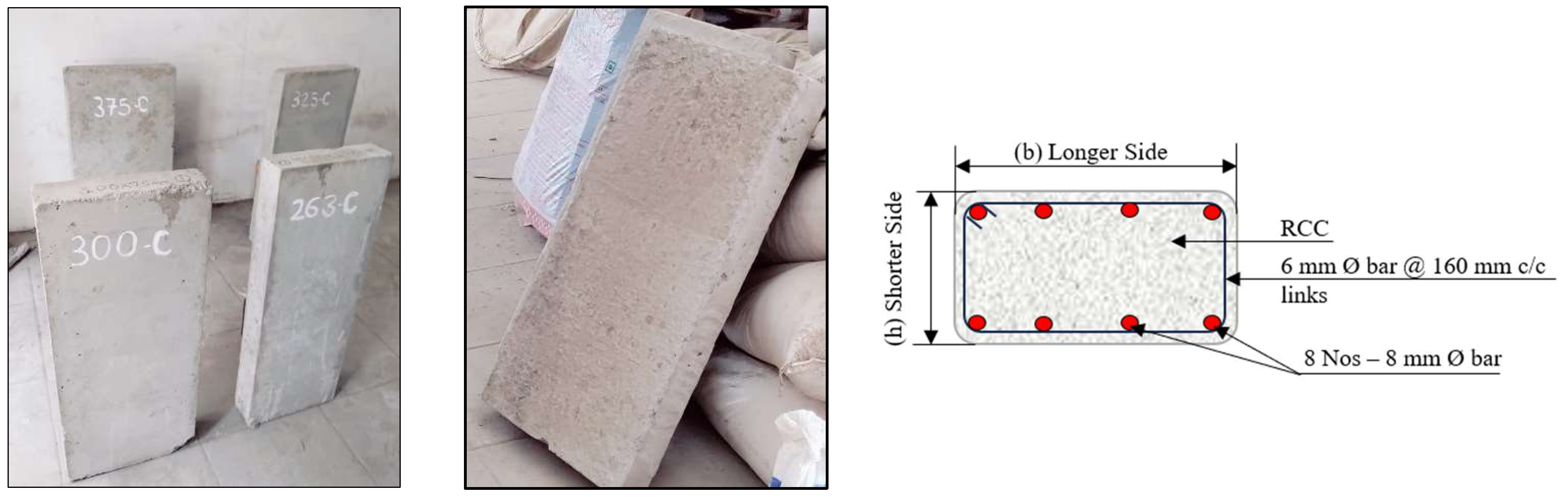
2.1. Column Specimens

Rectangular RCCs with aspect ratios exceeding 2 were used for experimentation. Three distinct aspect ratios were chosen, and the following column dimensions were selected for casting the specimens:
(a)
263 mm × 75 mm × 700 mm—Aspect ratio: 3.50
(b)
300 mm × 75 mm × 700 mm—Aspect ratio: 4.00
(c)
325 mm × 75 mm × 700 mm—Aspect ratio: 4.33
(d)
375 mm × 75 mm × 700 mm—Aspect ratio: 5.00
All the column specimens had a height of 700 mm, and a constant shorter side (h) of 75 mm. The longer side (b) was varied to achieve different aspect ratios for the column specimens. The half-scaled specimens were cast for testing.
Figure 1 presents the unconfined column specimens. The columns were reinforced with 8 bars of 8 mm diameter and 6 mm diameter links at 160 mm c/c. The grade of concrete used was M25. Twelve column specimens were cast, that is, three samples for each aspect ratio. Out of the twelve columns, eight columns were wrapped with the TRM system and tested for a confined compression load. Four columns were tested for unconfined compression loads. The TRM sheet utilized for column wrapping was composed of high-strength carbon fibers. This carbon TRM sheet is available in various areal weights, ranging from 200 g/m2 to 1200 g/m2; the sheet’s thickness and density vary accordingly, profoundly influencing its mechanical properties and overall performance. With a standardized width of 500 mm, the sheet features carbon fibers aligned in the zero-degree direction, ideal for applications necessitating robust tensile strength along its length. Crafted in a plain weaving style, the fabric ensures the uniform distribution of the warp and weft yarns, enhancing the structural integrity. The warp comprises either 12K or 24K carbon fibers, with the latter representing a higher filament count per strand. Complementing the carbon warp, the weft consists of thermo-fixed glass fibers, meticulously processed to augment the mechanical resilience. These carbon fibers showcase extraordinary strength, boasting a tensile strength that exceeds 4900 MPa, and an elastic modulus of 230 GPa. They indicate exceptional stiffness and resistance to the deformation when subjected to a load. Additionally, their elongation at break, reaching around 2.1%, illustrates a balanced combination of the flexibility and durability. With a density of approximately 1.8 g/cc, these carbon fibers maintain a balance between lightweight attributes and structural robustness, making the TRM sheet a versatile choice for various engineering applications.

2.2. Materials

As per the discussion in Section 1 of the current article, the aspect ratio of the column plays an important role in the strength enhancement of the confined columns [23]. The thickness of the cementitious mortar in TRM systems is critical for ensuring the effectiveness and durability of strengthening. Triantafillou et al. [12] applied a two-mortar layer of 3 mm thickness each for strengthening a masonry wall, while Ombres [27] focused on evaluating the confinement effects and mechanical improvements provided by the FRCM system. This study assessed various mortar thicknesses, ranging from 10 mm to 30 mm, to determine their impact on the structural performance of the confined columns. Thicker mortar layers generally provide better structural performance, but this should be balanced with considerations of the added weight and material costs. In the current study, an attempt was made to confine columns with different thicknesses of mortar layers to control their aspect ratio. Overall, the 2 layers of mortar ranged from 10 mm to 24 mm.
The process involved wrapping the columns with the TRM system, allowing for variations in the thickness of the mortar layer. This could be achieved in either a continuous or a discontinuous pattern, offering flexibility in the retrofitting approach.
Table 1 provides a comprehensive overview of the mechanical properties of the carbon textile sheets used for the confinement. These properties include important parameters of the material’s strength, stiffness, and deformation behavior, both at the individual fiber level and within the grid structure. This meticulous consideration of the mechanical properties ensures a detailed understanding of the performance of carbon TRM and its effect on confined columns, contributing to a robust evaluation of the retrofitting system in terms of the structural enhancement.
A high-strength mortar was designed and tested for its mechanical and compatibility properties. A total of 25 different mortar specimens were tested for their compressive, splitting tensile, and flexural capacities. The bond between the substrate surface and mortar was checked by compatibility tests, such as splitting tensile bond, slant shear, and direct pull-off bond tests. The bond between the carbon textile sheet and high-strength mortar was verified by a direct pull-out test. Out of the 25 samples, the mortar specimen which showed the best mechanical and compatibility capacities was chosen as the final mortar proportion to be applied to the column for the confinement.
Table 2 lists the details of the mechanical properties of the high-strength mortar selected (out of the 25 samples) for the confinement of the columns. The results revealed a high value of 52.1 MPa at 28 days, demonstrating a robust compressive strength. Its splitting tensile strength exhibited the highest value of 6.28 MPa at 28 days, displaying excellent resistance to tensile forces. Its flexural strength peaked at 15.7 MPa at 28 days, indicating strong resistance to bending stresses.
The mortar sample illustrated a balanced combination of cementitious materials, aggregates, and reinforcing fibers, resulting in excellent compressive, splitting tensile, and flexural strengths. The inclusion of micro silica, styrene butadiene rubber (SBR) latex, and a tailored combination of steel fiber and basalt fiber contributed synergistically to the superior performance of these mortar samples.
Table 3 presents the results of the compatibility tests for mortar. These results provide information about the strength and bonding characteristics of mortar for different tests. The values indicate how well mortar performed with the substrate surface and textile sheet under various types of stresses and loading conditions.
The bonding qualities of mortar were enhanced by the addition of fibers, such as steel and basalt fibers, to the mixture. Bonding agents and fibers work together to form a network in mortar which improves the mortar’s adherence to the textile sheet and substrate material. To achieve good adhesion, the substrate material and textile sheet must be properly prepared on the substrate surface. For a good bond between the mortar and substrate surface, priming, cleaning, and roughening of the surfaces are very important.

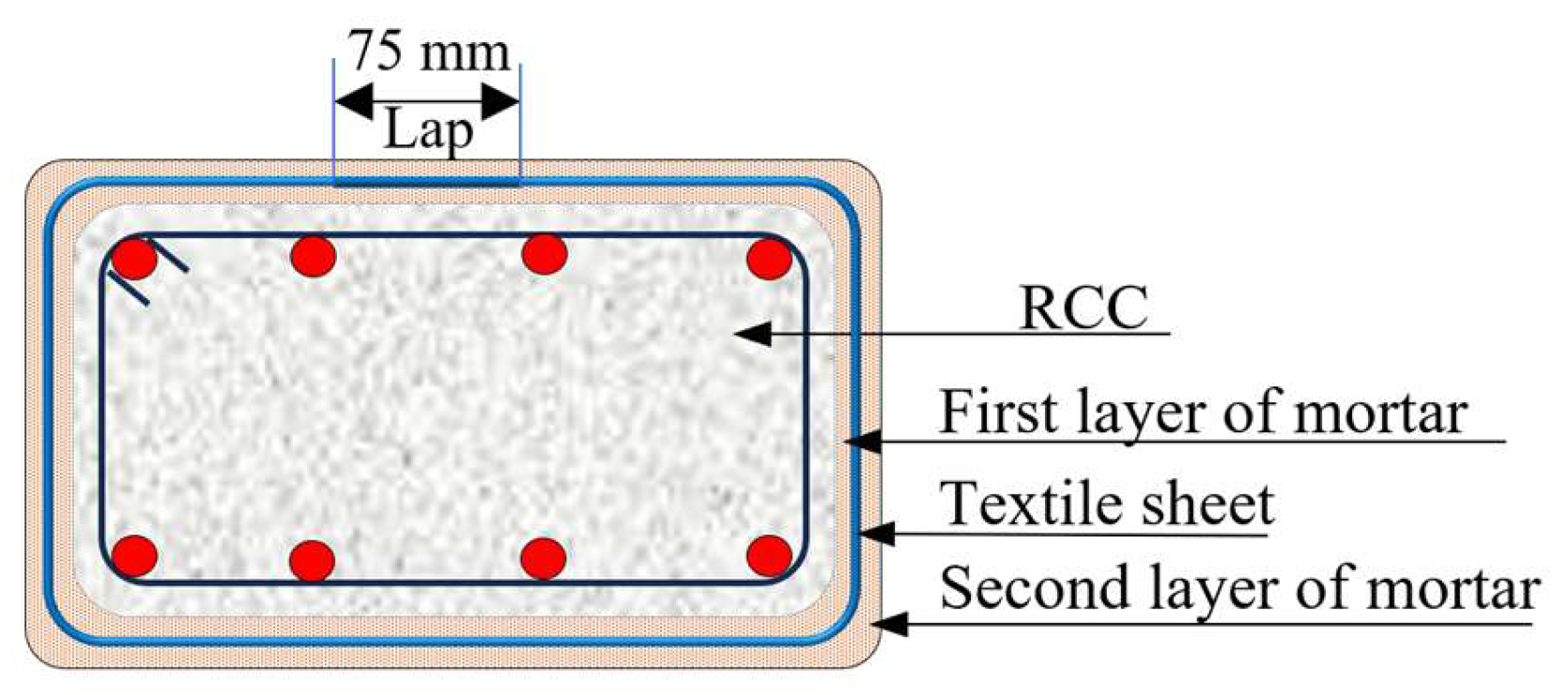
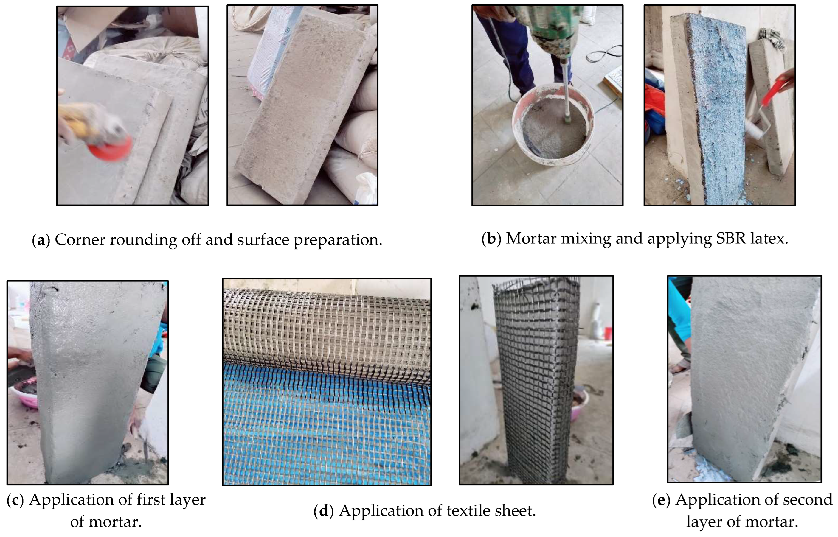
2.3. Method of Application

The column specimens were cast and cured for 28 days. After 28 days curing time, the unconfined specimens (labeled as C) were jacketed following the standard strengthening procedure. Two column specimens for each aspect ratio were selected for the confinement. The column corners were rounded off to a 20 mm radius and smoothed. The surfaces of the columns were cleaned to remove loose material and debris. The strengthening procedure involved the following steps:
  • The column surface was roughened to achieve a better bond between the mortar and column substrate.
  • The column surface was pre-wetted with water, such that it was in a surface-saturated dry condition.
  • A coat of SBR latex was applied on the roughened surface of the column, and the first layer of inorganic cementitious mortar was applied on it.
  • When mortar was still fresh, the textile sheet was slightly pressed into mortar. Only one layer of the textile sheet was used in the current study, and an overlapping length of 75 mm was provided.
  • This textile sheet was covered with a second layer of mortar and the outer surface was smoothened.
The finally finished samples were cured for 28 days and tested for the strength improvement. Figure 2 depicts the details of the layers of the repair system and Figure 3 shows the stepwise procedure to be followed during the application of the TRM system.
Table 4 outlines detailed information regarding the layers of mortar and final aspect ratios of the column specimens.

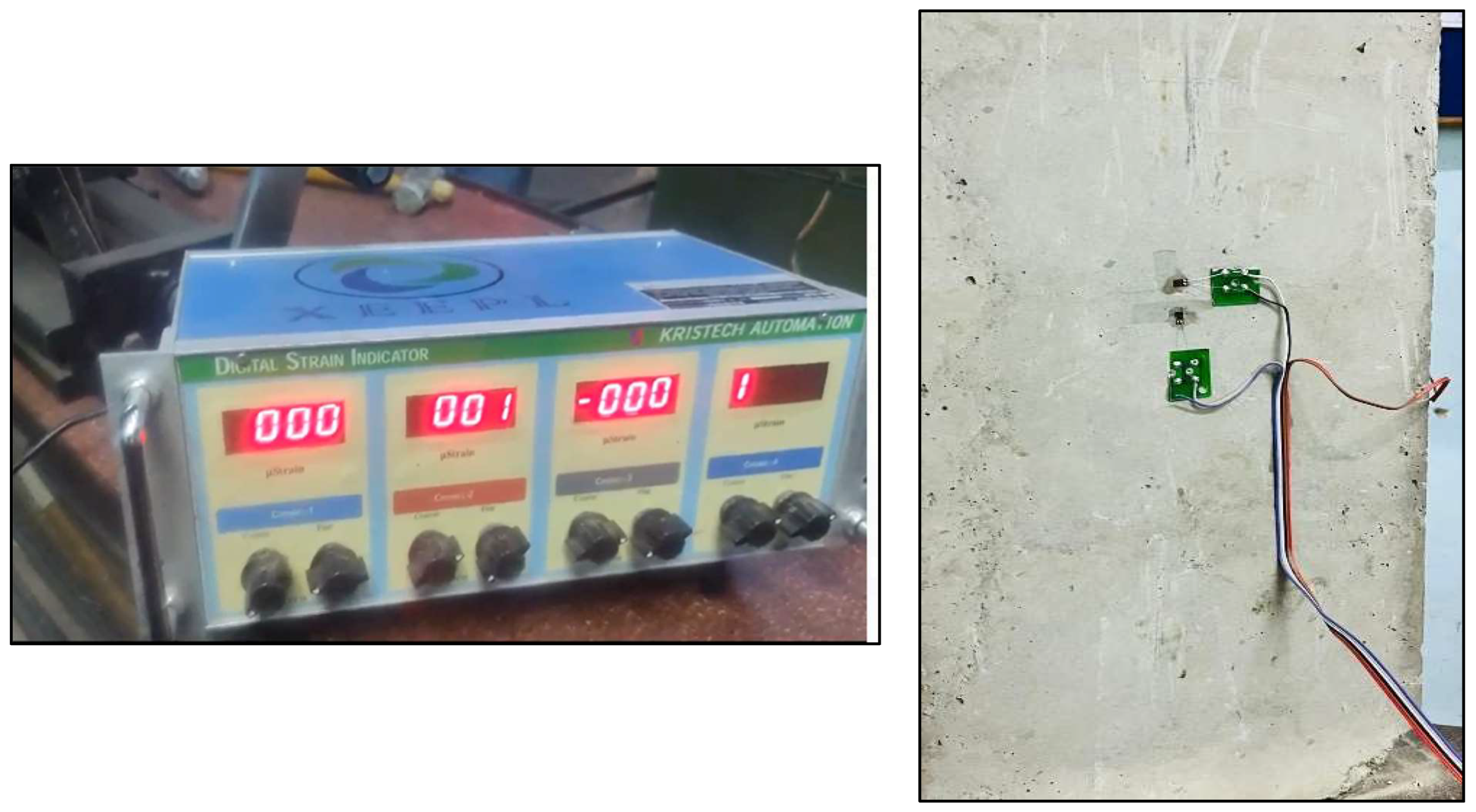
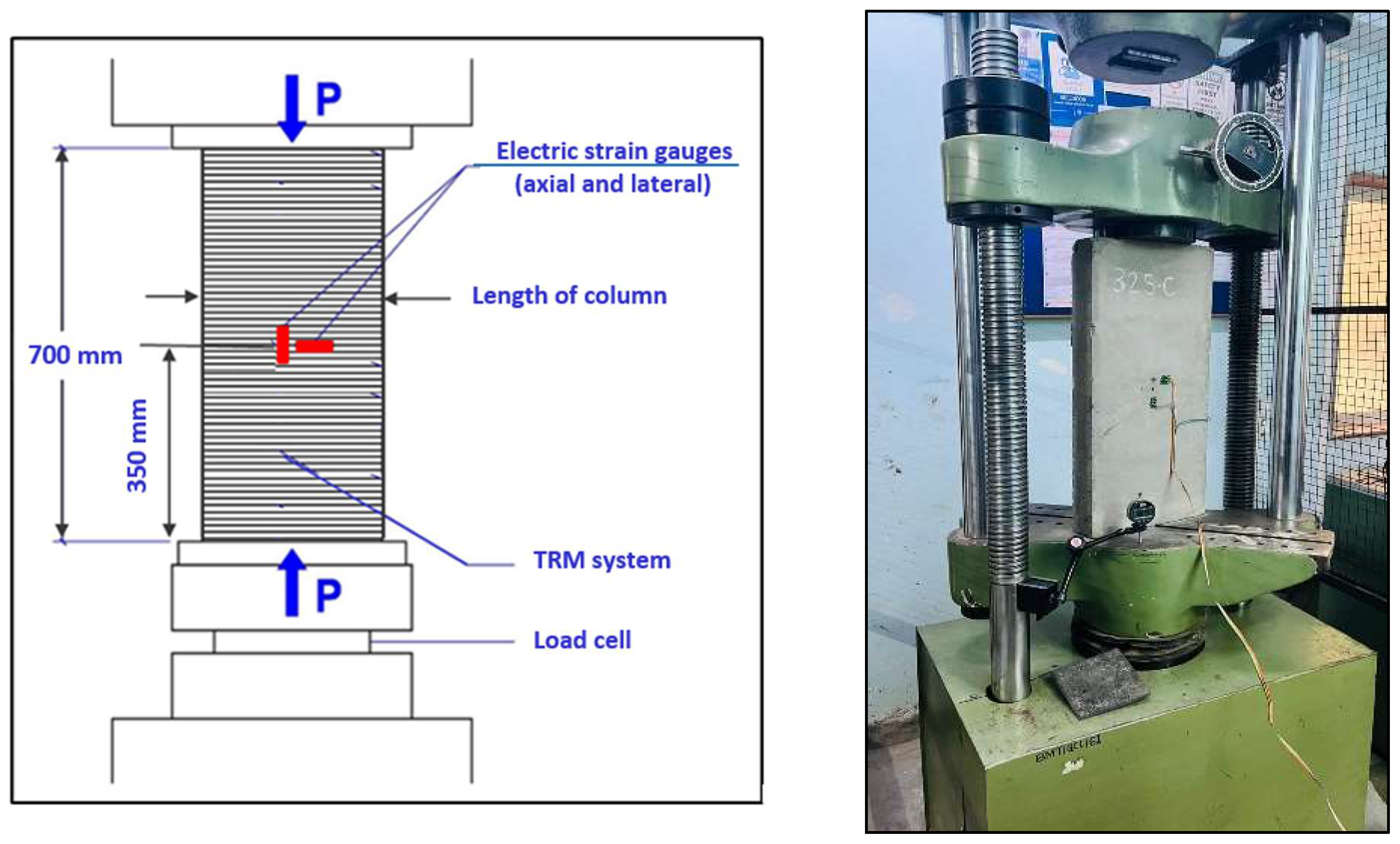
3. Experimental Setup

After 28 days of curing, the specimens were tested for the axial compression load using a universal testing machine (UTM) with a capacity of 600 kN. The displacements were recorded employing dial gauges. The strain values in the specimens were noted with the help of 5 mm 350E strain gauges and a digital strain indicator. The strain gauges were tightly bonded to the specimens.
During elongation or contraction, the electrical resistance of a metal wire changes. Strain gauges measure the strain in a specimen utilizing the principle of resistance change. To mount the strain gauges on a specimen, the surface was cleaned properly and smoothened with the help of sandpaper. Two gauges (one on the longer side of the column and the other on the shorter side of the column) were placed in the direction parallel to the line action of the load. The third gauge was mounted on the longer side of the column in the lateral direction. The center of height, width, and length were marked carefully using a scale and marker. The strain gauges were placed in the proper positions utilizing cello tape and glued to the surface employing adhesive. The soldering pads were fixed at positions near the strain gauges. These soldering pads were connected to the strain gauges and a digital strain indicator. The readings for the strain and displacement were noted at intervals of 25 kN loads. Figure 4 displays the mounting of the strain gauges on the surface and their connection with the column specimen.

4. Results and Discussion

This section presents a detailed discussion of the effects of the TRM confinement on the structural performance of RCCs, having different aspect ratios under axial loading. A non-destructive rebound hammer test was carried out on the unconfined samples to check the characteristic strength of concrete used for casting the column specimens. The compressive load-carrying capacity of both the confined and unconfined columns were checked. The displacements and strains were recorded for every 25 kN load interval. A failure pattern was observed for all the specimens.

4.1. Load-Carrying Capacity of Columns and Aspect Ratio

According to the non-destructive rebound hammer test, the compressive strength of concrete in the unconfined columns was 25 MPa. The peak compression loads of the column specimens are given in Table 5. A comparative graph for peak load increment is illustrated in Figure 5. It is observed that by controlling the aspect ratio of the columns, the load-carrying capacity of the columns can be enhanced. When determining the thickness of the mortar layers around the columns, a reduction in the aspect ratios of the columns can be considered. From Table 5 and Figure 5, it can be clearly seen that for the aspect ratios of the columns ranging from three to two, the improvement in the strength of the confined concrete ranges from 50% to 129%.
For the 263 series, the aspect ratio reductions for 263-CC1 and 263-CC2 as 15.15% and 33.42%, respectively, resulted in significant percentage increases in the peak load compared to that of 263-C. Specifically, 263-CC1 demonstrated a 113.33% increase in the peak load, while 263-CC2 exhibited a percentage increase of 129.78%. For the 300 series, the aspect ratio reductions from 4.0 to 2.83 for 300-CC1, and to 2.63 for 300-CC2, contributed to the strength increments of 77.08% and 83.33%, respectively. The strength increments observed for the 325-CC and 375-CC series, when compared to the 263 and 300 series, were comparatively lower. For the 375 series, when the aspect ratio was reduced from 5.0 to 4.16 and 3.24, the strength increments ranged from 3% to 8.54% for the 375-CC1 and 375-CC2 series, respectively. An analysis of the peak strength across all the series suggests that the TRM sheet proves more effective when the aspect ratio of the columns was less than three.

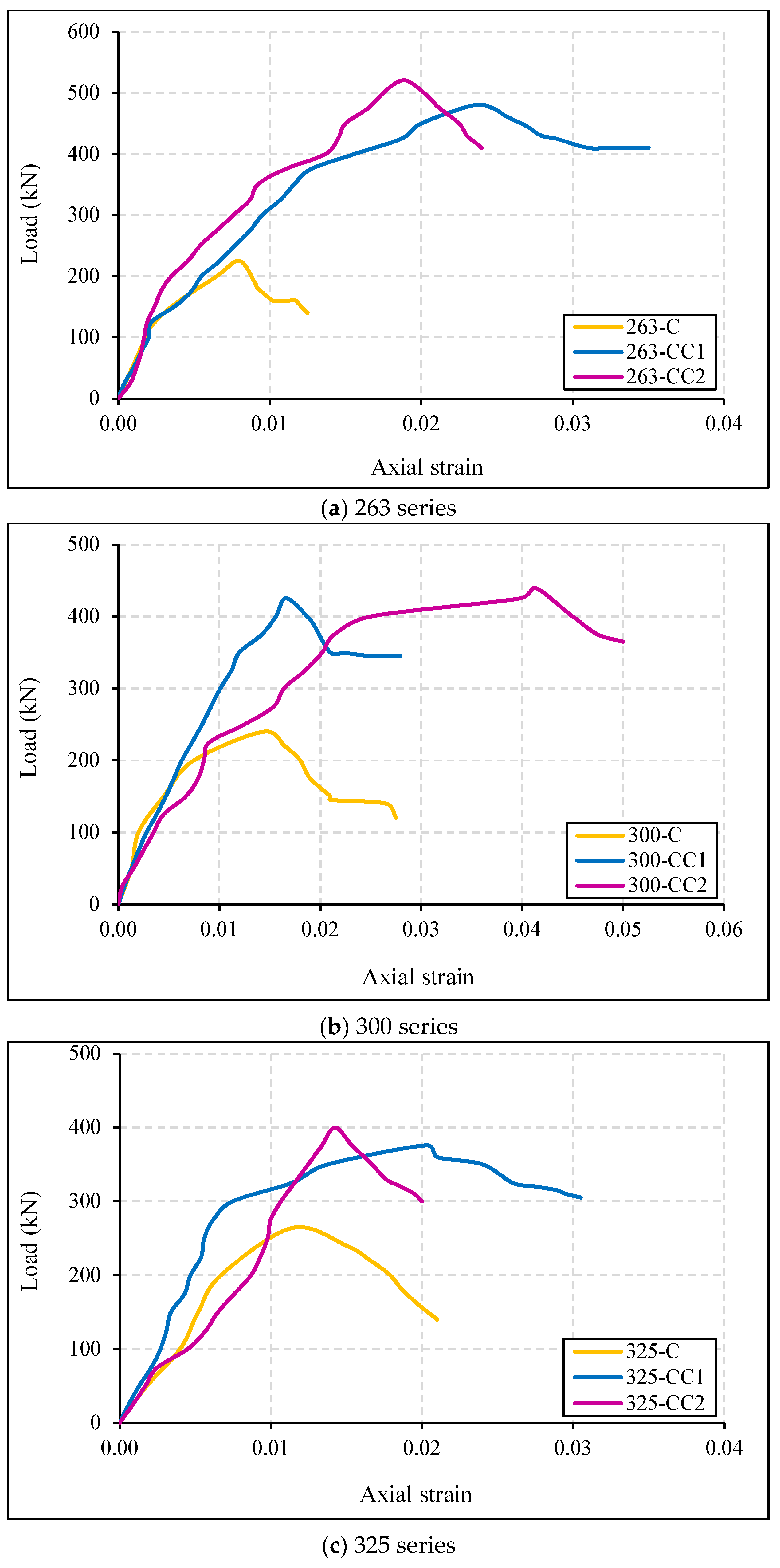
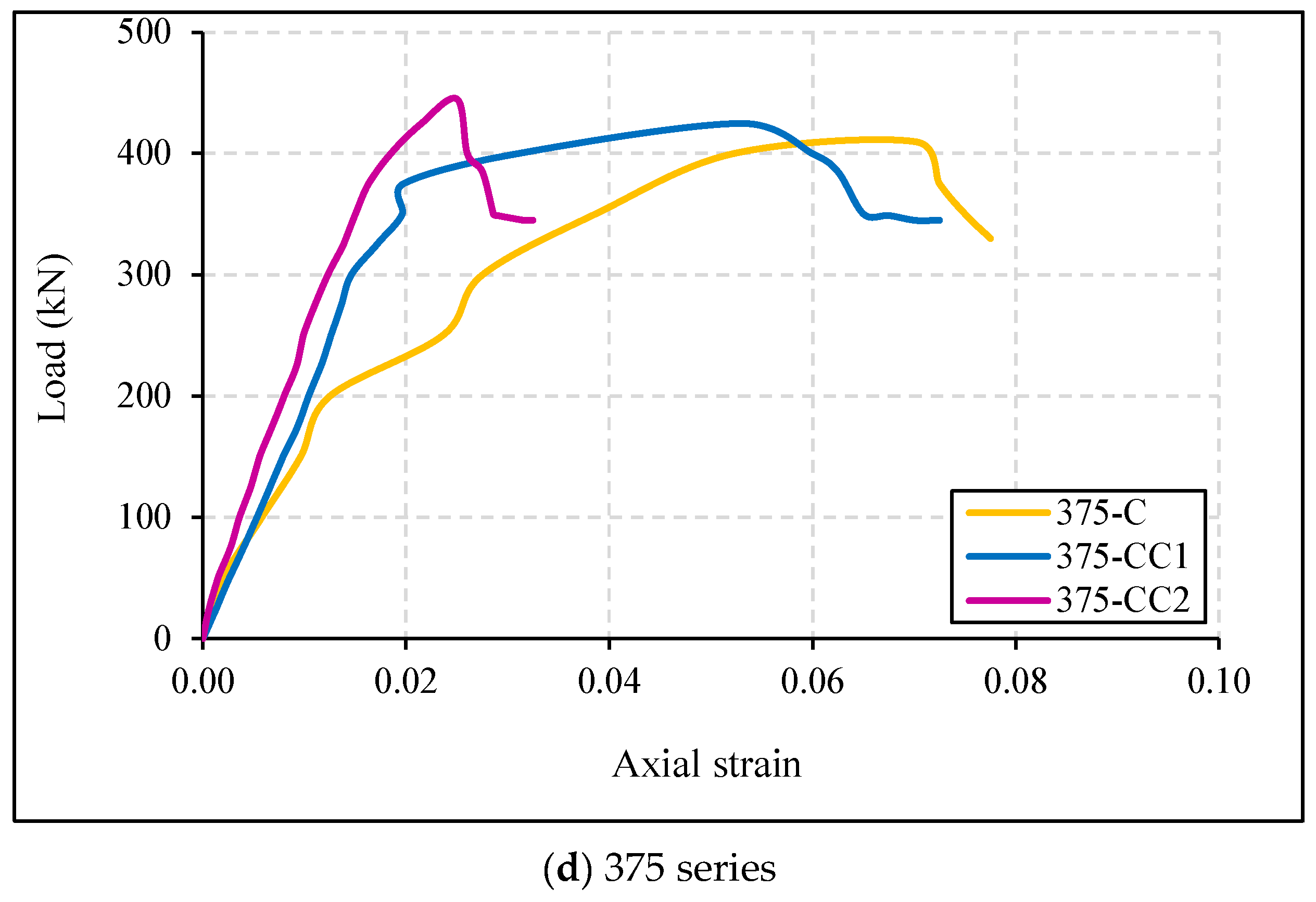
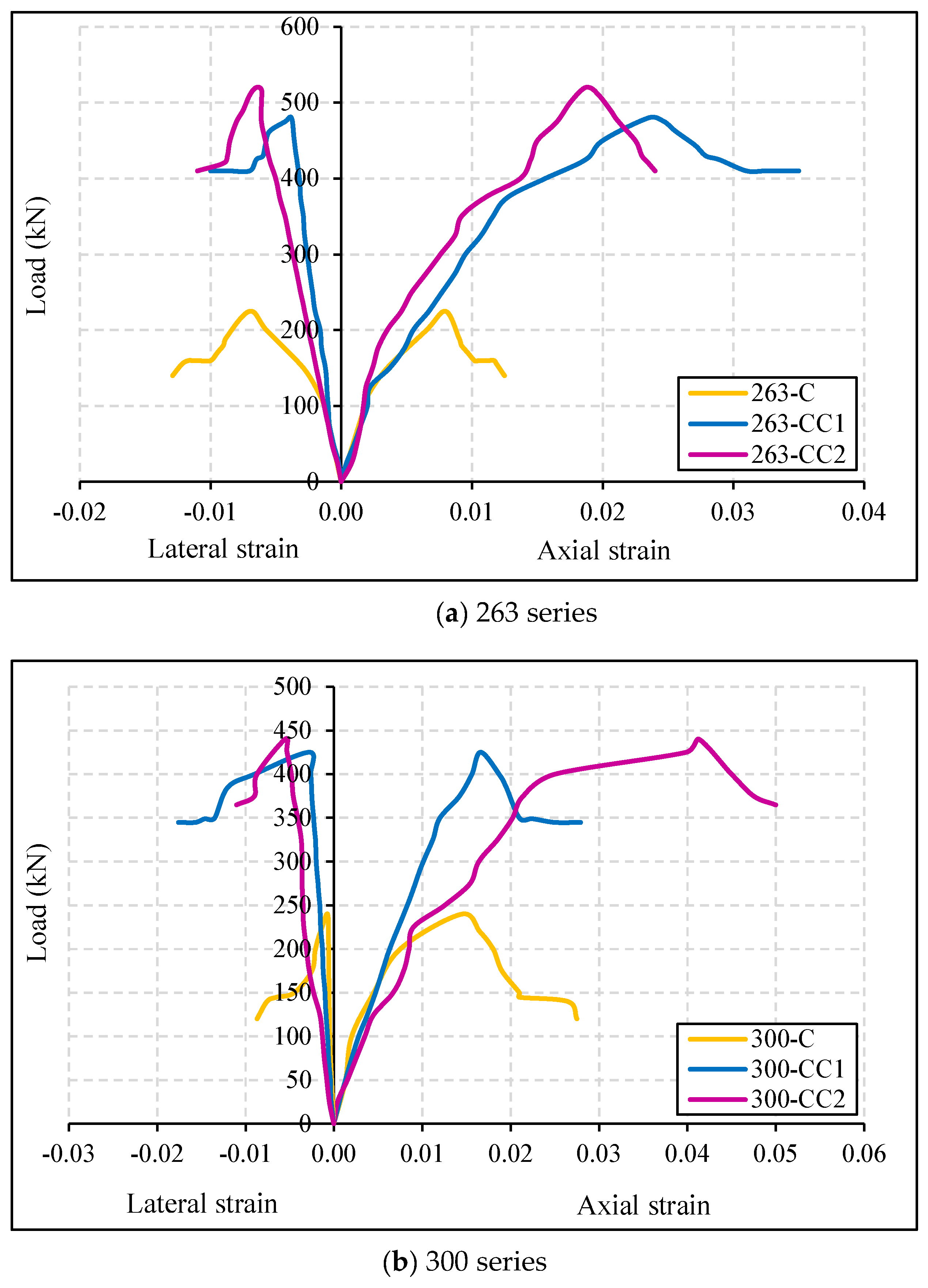
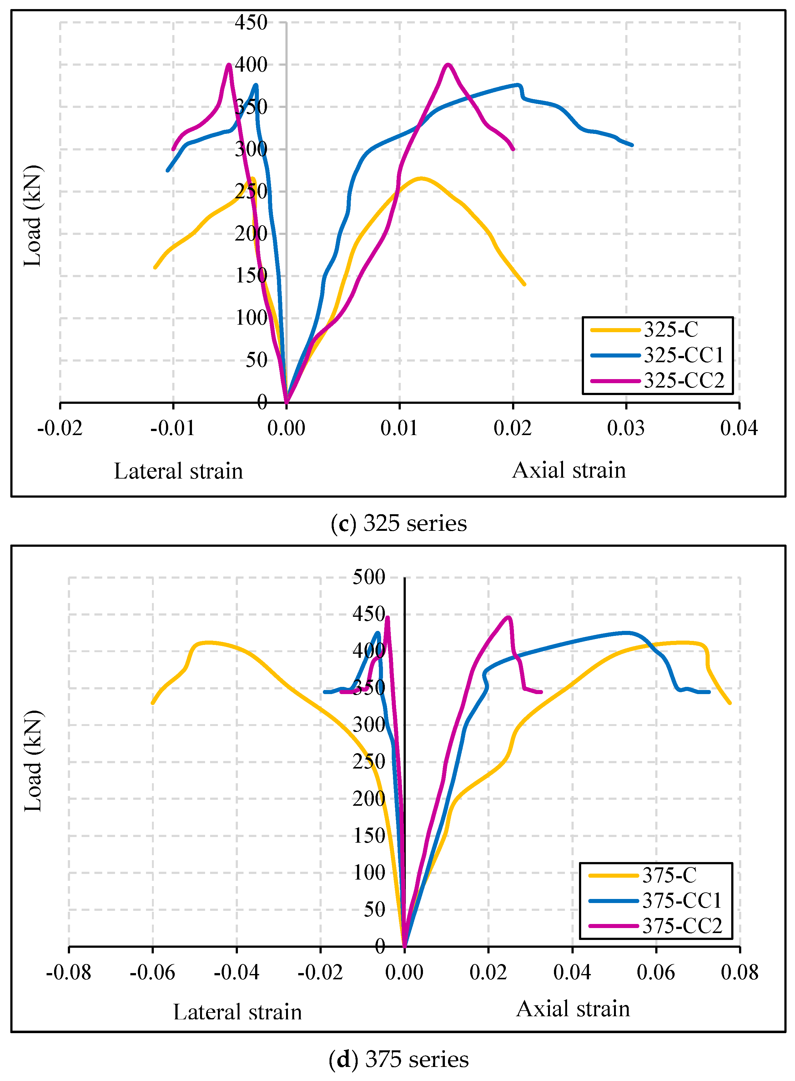
4.2. Load–Axial Strain Response

The load–axial strain responses are displayed in Figure 6. The axial strains were derived from the strain gauges aligned parallel to the applied load. Notably, there was an absence of a sudden drop in the curve across all the graphs, attributable to the reinforcement incorporated into each column. The unconfined columns showed low strength and deformability. In contrast, the confined columns illustrated an ascending branch leading up to the peak load. The confined columns depicted an ability to withstand higher loads without experiencing abrupt failures.
The confined columns (CC1 and CC2) consistently indicated higher peak strain values compared to the unconfined columns (C) within each series. The reduction in the aspect ratio of the confined columns generally led to an increase in the peak strain values, demonstrating an improved ductility and deformation capacity due to the TRM confinement. The recorded peak axial strain for the confined specimen 375-CC1 was 0.053, when there was a 16.8% reduction in the aspect ratio. The highest increase in the peak strain values was observed in the 300 series, particularly for CC2. 300-CC2 exhibited a remarkable 83.33% increase in its load-carrying capacity, with a peak axial strain value of 0.04125. 300-CC2 had a 65.75% reduction in its aspect ratio, which showed that the aspect ratio has a significant effect on the load-carrying capacity of a column. The effectiveness of the TRM confinement for enhancing the peak strain values is evident across the different series, highlighting its importance for improving the performance of columns under loading conditions.

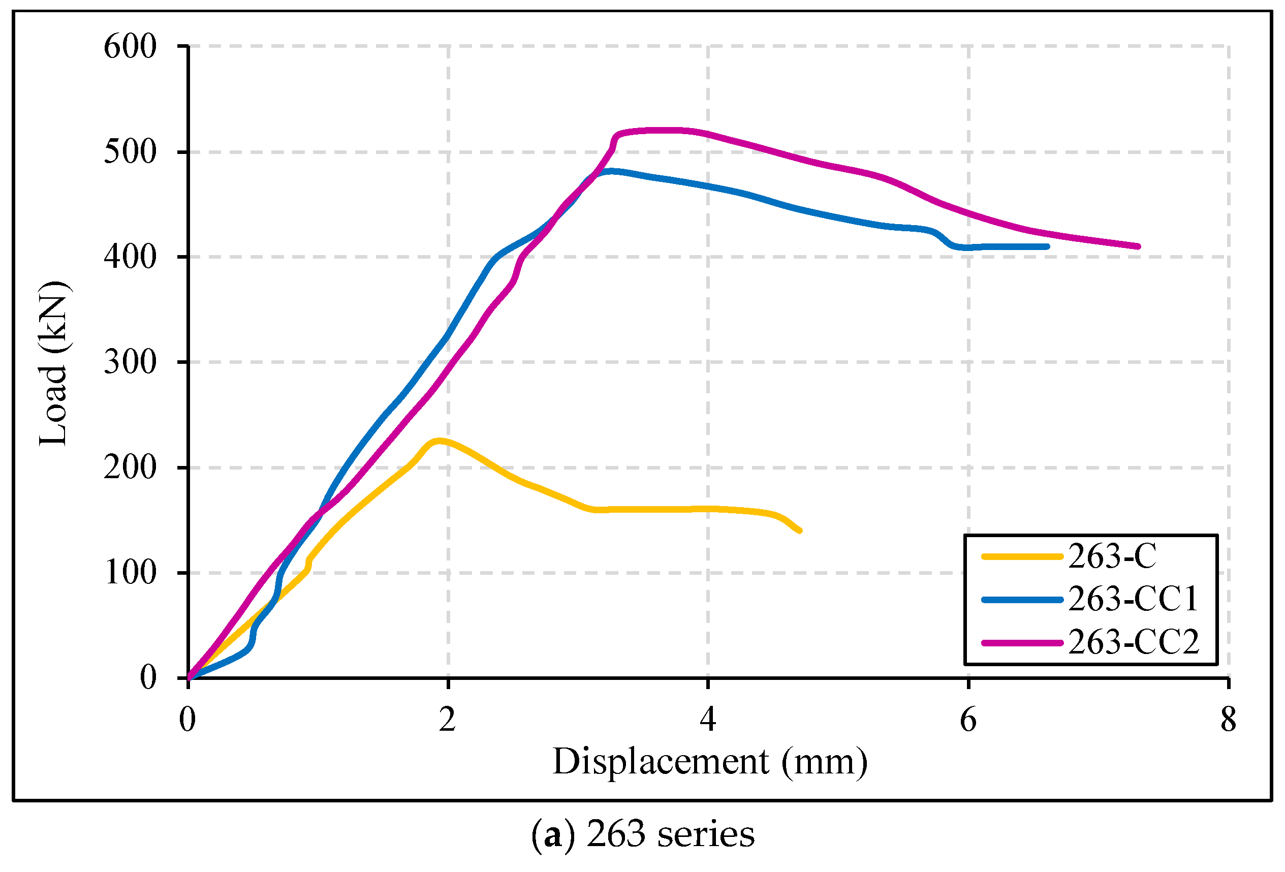
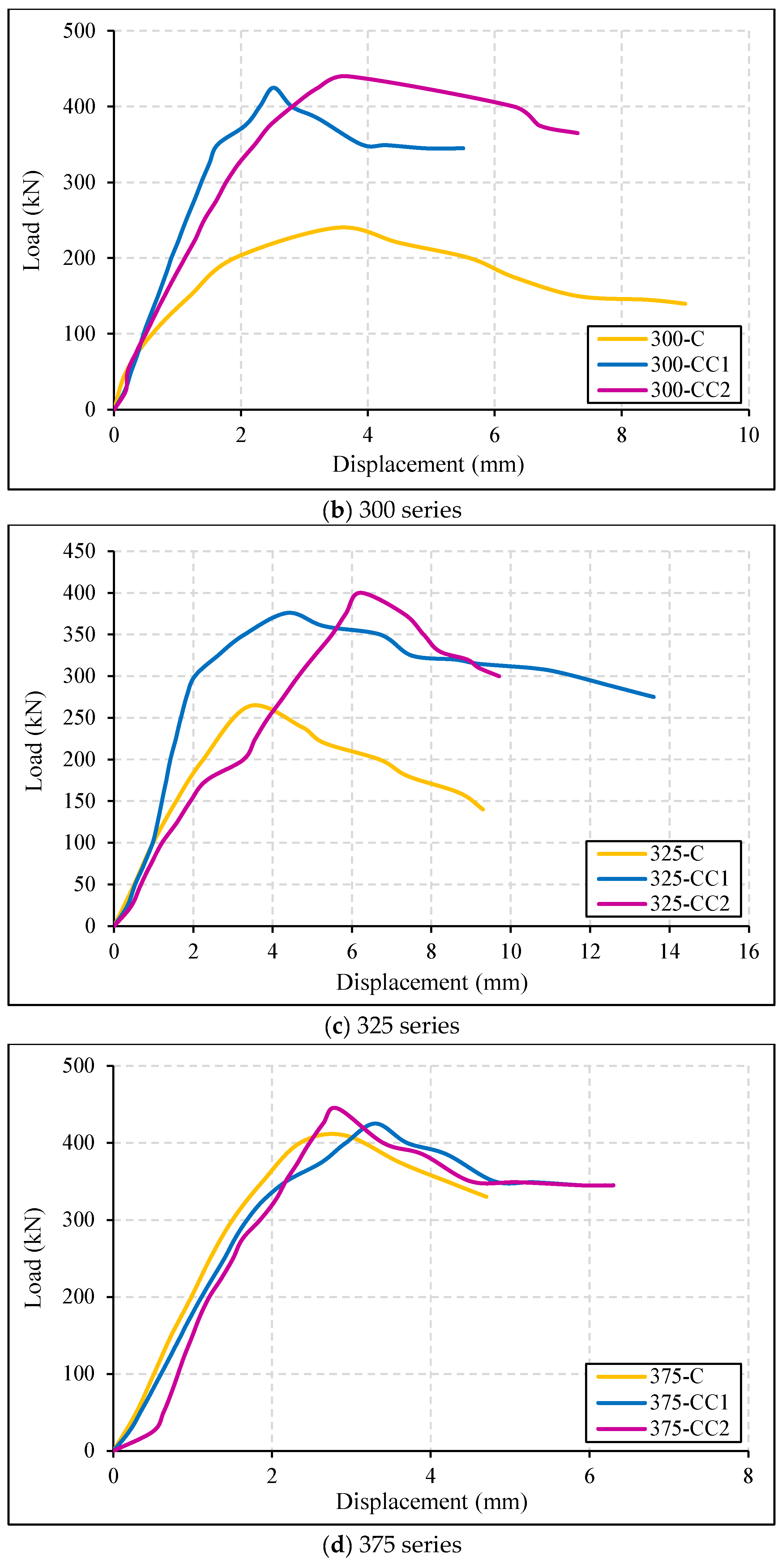
4.3. Load–Displacement Response

Figure 7 displays the load–displacement responses for both the confined and unconfined columns. Specifically, for the unstrengthened columns, there was a reduction in the load-carrying capacity accompanied by higher displacement. Conversely, in the case of the strengthened columns, there was a substantial increase in the load-carrying capacity, coupled with less displacement compared to their unconfined counterparts.
Confinement restricts lateral bulging and enhances a column’s axial load-carrying capacity, leading to reduced displacement compared to unconfined columns. In the 375-CC series, the enhancement of the strength was comparatively minimal. The load–displacement curve for this series closely resembled that of the unconfined 375-C, suggesting that the strength improvement for the confined columns of the 375-CC series was not as pronounced, and their overall performance aligned more closely with that of the unconfined columns.

4.4. Load–Strain Response

Figure 8 provides a representation of the relationship between the load, axial strain, and lateral strain. The axial strains were derived from strain gauges aligned parallel to the applied load, whereas the lateral strains were obtained from gauges placed perpendicular to the line of action of the load. The unconfined columns, as illustrated in the graph, indicated lower strength and deformability, evident from the observed drop in the graph. However, the confined columns showed a distinct ascending branch leading up to the peak load with less lateral strain. The lateral confinement provided by the TRM sheet contributed to reduced lateral strains with higher peak compressive strength.
The recorded peak lateral strain for the unconfined 375-C was 0.049. In contrast, the confined 375-CC1 and 375-CC2 exhibited peak lateral strain values of 0.00634 and 0.0041, respectively, which had 87% and 91.6% reductions in the lateral strain, respectively. 263-CC2, which had the smallest aspect ratio of 2.33, demonstrated a peak lateral strain of 0.0061, whereas unconfined 263-C (having an aspect ratio of 3.5) had a peak lateral strain of 0.007. The reduction in the aspect ratio and confinement with the TRM system reduced the lateral strain by 12.85%. This observation underscores the significant role of reducing the aspect ratio during the column’s strengthening for improving the strength and reducing the deformation. The confined columns displayed smaller lateral strain values compared to the unconfined columns under similar loading conditions. This was because confinement techniques reduce the lateral deformation and enhance the column’s stiffness. The confinement restricts the lateral expansion of a column, resulting in less lateral strain and more axial compression. This enhances the column’s load-carrying capacity and structural stability.
Triantafillou et al. [23] tested a total of 45 RCCs measuring 150 × 450 mm or 150 × 600 mm in the cross-sectional dimension with an aspect ratio of three or four. CFRP jackets without anchors provided a moderate increase in the axial strength, in the area of 40% or 25%, for columns with an aspect ratio of three or four, respectively. This indicates that the strength enhancement through the confinement is less for columns having a high aspect ratio. Researchers also observed that the shape enlargement of the cross-section with mortar is practically as effective as the use of (heavy) anchors.

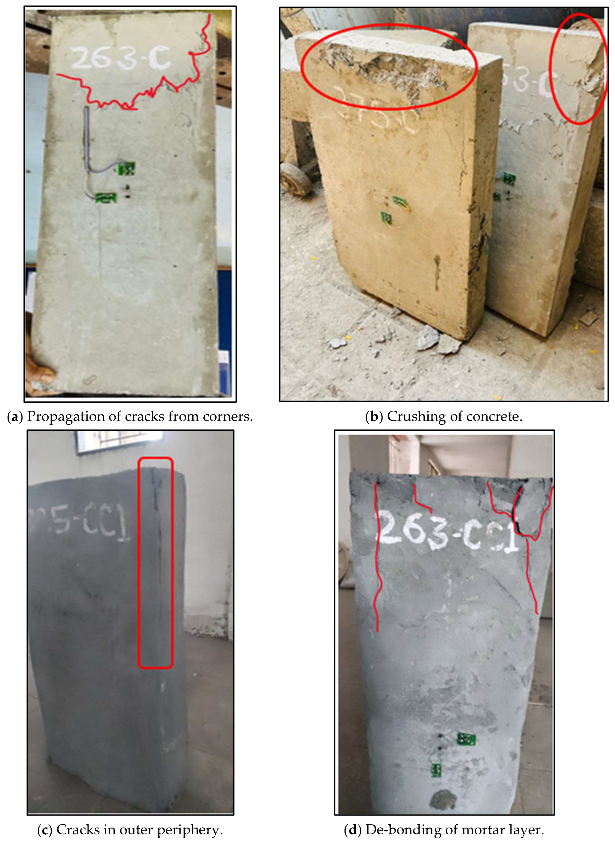
4.5. Failure Patterns

Figure 9 presents a comprehensive overview of the failure modes observed in both the unconfined and confined specimens, offering valuable insights into their structural behavior under different loading conditions.
  • Unconfined Columns
A consistent failure pattern was identified in the case of the unconfined columns. Cracks initiated from the edges of the columns and propagated vertically toward the centerline of the samples. The ultimate failure mechanism was attributed to crushing of concrete, which is a common behavior of unrestrained concrete subjected to axial loads. This observation aligns with traditional failure modes associated with unconfined columns.
  • Confined Columns
The confined columns illustrated two distinct failure patterns, indicative of the impact of the TRM system on their performance.
-
Visible Vertical Cracks on Outer Periphery
One observed failure mode in the confined columns involved the development of visible vertical cracks, which were notably confined to the outer periphery of the columns. This outcome suggests that the TRM system effectively restrained the cracks propagation, limiting it to the outer boundaries. The presence of cracks primarily at the periphery signifies the load-carrying improvement achieved through the efficient operation of the TRM system. Some columns also exhibited cracks in the core area, coinciding with the mortar failure.
-
De-Bonding of Mortar Layer from Top
Another identified failure mode in the confined columns was the de-bonding of the mortar layer from the top of the column. This occurs when the mortar layer, responsible for providing additional confinement, loses its adhesion or bonds with the underlying concrete. De-bonding was a common failure of several specimens.
The presence of both visible vertical cracks and instances of de-bonding highlights the multifaceted nature of failure in the confined columns. The cracks on the outer periphery demonstrated the load-enhancing efficiency of the TRM system. Additionally, the coexistence of cracks in the core area and de-bonding emphasizes the need for a comprehensive understanding of the failure modes, as these can vary among specimens. In conclusion, the findings underscore the importance of the TRM system in altering the failure patterns, enhancing the load-carrying capacity, and influencing the overall performance of the confined columns under axial loads.

5. Conclusions

A total of 12 column samples were tested, of which 4 were unconfined and denoted as the C series, and 8 were confined (CC series) with the TRM system. The aspect ratio of the confined columns was reduced by controlling the thickness of mortar. From the research work carried out herein, the conclusions are as follows:
  • The thickness of the mortar layers around the columns, particularly considering the reduction in the aspect ratios, played a crucial role. The analysis showed the strength improvements of 50% to 129% for the columns with the aspect ratios ranging from three to two, with the workmanship impacting the strength enhancement.
  • A reduction in the aspect ratio from 5 to 4.16 and 3.24, respectively, resulted in an increase in the load-carrying capacity of up to 3.65% and 8.53%, respectively.
  • In general, the unconfined columns indicated a reduced load-carrying capacity with higher displacements, whereas the strengthened columns displayed substantial capacity increments with less displacement. The 375-CC series illustrated minimal strength enhancement, closely aligning with the unconfined columns.
  • 375-CC1, with a 16.8% reduction in the aspect ratio, presented a peak axial strain of 0.053 and a 3.65% increment in the peak load. The most noticeable increase in the peak strain values was observed in the 300 series, particularly for the CC2 column. 300-CC2, with a 65.75% reduction in the aspect ratio, depicted an 83.33% increase in the load-carrying capacity and a peak axial strain value of 0.04125.
  • 263-CC2, which had the smallest aspect ratio, exhibited a peak lateral strain of 0.0061, whereas the unconfined 263-C had a peak lateral strain of 0.007. The reduction in the aspect ratio and the confinement by the TRM system reduced the lateral strain by 12.85%.
  • The bonding of the TRM system with the substrate was a very important factor when considering the failure of the columns. The properties of the designed mortar, which affected the overall performance of the TRM system, were very important.
  • The failure patterns of the unconfined and confined columns were distinct. The unconfined columns demonstrated a consistent failure pattern with cracks initiating from the edges and propagating vertically. The confined columns, under the influence of the TRM system, showed two failure patterns as visible vertical cracks on the outer periphery and de-bonding of the mortar layer from the top.
Despite the large number of parameters examined in the present study, further investigation is needed to study the effects of multiple layers of TRM sheets and with other TRM materials.

Author Contributions

Conceptualization, M.S., A.B. and P.M.; methodology, M.S., A.B. and P.M.; validation, M.S., A.B., P.M. and R.S.C.; formal analysis, A.B.; investigation, M.S., A.B. and P.M.; resources, A.B.; writing—original draft preparation, M.S., A.B. and P.M.; writing—review and editing, M.S., A.B., P.M. and R.S.C. All authors have read and agreed to the published version of the manuscript.

Funding

This research received no external funding.

Data Availability Statement

Data will be made available upon reasonable request.

Conflicts of Interest

The authors declare no conflicts of interest.

References

  1. Liao, H.; Ren, R.; Li, L. Existing Building Renovation: A Review of Barriers to Economic and Environmental Benefits. Int. J. Environ. Res. Public Health 2023, 20, 4058. [Google Scholar] [CrossRef] [PubMed]
  2. Ganesh, P.; Murthy, A.R. Repair, Retrofitting and Rehabilitation Techniques for Strengthening of Reinforced Concrete Beams—A Review. Adv. Concr. Constr. 2019, 8, 101–117. [Google Scholar] [CrossRef]
  3. Rajak, D.K.; Pagar, D.D.; Menezes, P.L.; Linul, E. Fiber-Reinforced Polymer Composites: Manufacturing, Properties, and Applications. Polymers 2019, 11, 1667. [Google Scholar] [CrossRef] [PubMed]
  4. Vivekanandan, R.; Aarthi, K. Behavior of Hybrid FRP Strengthened RC Column Under Axial Compression. Iran. J. Sci. Technol. Trans. Civ. Eng. 2023, 48, 1933–1945. [Google Scholar] [CrossRef]
  5. Shewale, M.; Murthi, P.; Chidambaram, S. Functional Performance of Textile Reinforced Mortar in Strengthening Structural Members: A Critical Review. AIP Conf. Proc. 2023, 2764, 50003. [Google Scholar]
  6. Shaikh, F.U.A.; Bamisile, O. Effect of High Temperatures on the Mechanical Properties of Fiber-Reinforced Cementitious Composites. J. Compos. Constr. 2023, 27, 4023011. [Google Scholar] [CrossRef]
  7. Veiga, M.R.; Magalhães, A.C.; Silva, C.; Silvestre, N. Durability of Textile Reinforced Mortars for the Reinforcement of Concrete Structures: Influence of Elevated Temperatures. Compos. Struct. 2020, 240, 112122. [Google Scholar] [CrossRef]
  8. Triantafillou, T. Textile-Reinforced Mortars (TRM). In Composite Materials; Nicolais, L., Meo, M., Milella, E., Eds.; Springer: London, UK, 2011. [Google Scholar] [CrossRef]
  9. Curbach, M.; Jesse, F. High-Performance Textile-Reinforced Concrete. Struct. Eng. Int. IABSE 1999, 4, 289–291. [Google Scholar] [CrossRef]
  10. Brameshuber, W.; Brockmann, J.; Roessler, G. Textile Reinforced Concrete for Formwork Elements—Investigations of Structural Behaviour. In Proceedings of the FRPRCS5, 5th International Conference on Fibre-Reinforced Plastics for Reinforced Concrete Structures, Cambridge, UK, 16–18 July 2001; pp. 1019–1026. [Google Scholar]
  11. Triantafillou, T.C.; Papanicolaou, C.G. Shear Strengthening of Reinforced Concrete Members with Textile Reinforced Mortar (TRM) Jackets. Mater. Struct. 2006, 39, 85–93. [Google Scholar]
  12. Triantafillou, T.C.; Papanicolaou, C.G.; Zissimopoulos, P.; Laourdekis, T. Concrete Confinement with Textile Reinforced Mortar (TRM) Jackets. ACI Struct. J. 2006, 103, 28–37. [Google Scholar]
  13. Bournas, D. Strengthening of Existing Structures: Selected Case Studies. In Textile Fibre Composites in Civil Engineering; Triantafillou, T.C., Ed.; Woodhead Publishing: Cambridge, UK, 2016; Chapter 17; pp. 389–411. [Google Scholar]
  14. Cascardi, A.; Longo, F.; Micelli, F.; Aiello, M.A. Compression Strength of Confined Columns with Fiber Reinforced Mortar (FRM): New Design-Oriented Models. Constr. Build. Mater. 2017, 156, 387–401. [Google Scholar] [CrossRef]
  15. Leone, M.; Aiello, M.A.; Balsamo, A.; Carozzi, F.G.; Ceroni, F.; Corradi, M.; Gams, M.; Garbin, E.; Gattesco, N.; Krajewski, P.; et al. Glass Fabric Reinforced Cementitious Matrix: Tensile Properties and Bond Performance on Masonry Substrate. Compos. Part B Eng. 2017, 127, 196–214. [Google Scholar] [CrossRef]
  16. Kariou, F.; Triantafyllou, S.; Bournas, D.A.; Koutas, L. Out-of-Plane Response of Masonry Walls Strengthened using Textile-Mortar System. Constr. Build. Mater. 2018, 165, 769–781. [Google Scholar] [CrossRef]
  17. Peled, A.; Bentur, A.; Mobasher, B. Textile Reinforced Concrete, 1st ed.; CRC Press: Boca Raton, FL, USA, 2017. [Google Scholar] [CrossRef]
  18. Brameshuber, W. Textile Reinforced Concrete: State of the Art Report; RILEM TC-201-TRC, Report 36; RILEM Publications: Aachen, Germany, 2006. [Google Scholar]
  19. De Felice, G.; De Santis, S.; Garmendia, L.; Ghiassi, B.; Larrinaga, P.; Lourenco, P.B.; Oliveira, D.V.; Paolacci, F.; Papanicolaou, C.G. Mortar-Based Systems for Externally Bonded Strengthening of Masonry. Mater. Struct. 2014, 47, 2021–2037. [Google Scholar] [CrossRef]
  20. De Santis, S.; de Felice, G. Steel Reinforced Grout Systems for the Strengthening of Masonry Structures. Compos. Struct. 2015, 134, 533–548. [Google Scholar] [CrossRef]
  21. Rampini, M.C.; Zani, G.; Colombo, M.; Di Prisco, M. Textile Reinforced Concrete Composites for Existing Structures: Performance Optimization via Mechanical Characterization. In Proceedings of the 12th Fib International PhD Symposium in Civil Engineering, Prague, Czech Republic, 29–31 August 2018; pp. 907–914. [Google Scholar]
  22. Koutas, L.N.; Tetta, Z.; Bournas, D.A.; Triantafillou, T.C. Strengthening of Concrete Structures with Textile Reinforced Mortars: State-of-the-Art Review. J. Compos. Constr. 2019, 23, 3118001. [Google Scholar] [CrossRef]
  23. Triantafillou, T.C.; Choutopoulou, E.; Fotaki, E.; Skorda, M.; Stathopoulou, M.; Karlos, K. FRP Confinement of Wall-Like Reinforced Concrete Columns. Mater. Struct. 2016, 49, 651–664. [Google Scholar] [CrossRef]
  24. Hosny, A.; Shahin, H.; Abdelrahman, A.; El-Afandy, T. Strengthening of Rectangular RC Columns using CFRP. In Proceedings of the 5th International Conference on Fibre-Reinforced Plastics for Reinforced Concrete Structures, Cambridge, UK, 16–18 July 2001; pp. 773–782. [Google Scholar]
  25. Tan, K.H. Strength Enhancement of Rectangular Reinforced Concrete Columns Using Fiber-Reinforced Polymer. J. Compos. Constr. 2002, 6, 175–183. [Google Scholar] [CrossRef]
  26. Tanwongsval, S.; Maalej, M.; Paramasivam, P. Strengthening of RC Wall-Like Columns with FRP under Sustained Loading. Mater. Struct. 2003, 36, 282–290. [Google Scholar] [CrossRef]
  27. Ombres, L. Confinement Effectiveness in Concrete Strengthened with Fiber Reinforced Cement Based Composite Jackets. In Proceedings of the FRPRCS-8, Patras, Greece, 16–18 July 2007. [Google Scholar]
Figure 1. Unconfined column specimens.
Buildings 14 02050 g001
Figure 2. Layers of repair system.
Buildings 14 02050 g002
Figure 3. Application procedure for TRM.
Buildings 14 02050 g003
Figure 4. Strain gauges connection.
Buildings 14 02050 g004aBuildings 14 02050 g004b
Figure 5. Peak compression load for column specimens.
Buildings 14 02050 g005
Figure 6. Load–axial strain responses for specimens.
Buildings 14 02050 g006aBuildings 14 02050 g006b
Figure 7. Load–displacement responses for specimens.
Buildings 14 02050 g007aBuildings 14 02050 g007b
Figure 8. Load–strain responses for specimens.
Buildings 14 02050 g008aBuildings 14 02050 g008b
Figure 9. (a,b) Failure modes for unconfined columns; (c,d) Failure modes for confined columns.
Buildings 14 02050 g009
Table 1. Properties of textile sheet (from manufacturer’s data sheet).
PropertyValuePropertyValue
Dry Fiber PropertyGrid Property
Density filament 1.8 g/cc Grid size 20 × 20 mm
Tensile strength 4900 MPaAerial weight (GSM) 250 g/m2
Tensile modulus 230 GPaUltimate tensile force 150 kN/m
Elongation 1.6%Elastic modulus 230 kN/mm2
Diameter 7 microns--
Table 2. Mechanical properties of mortar.
DayCompressive Strength (MPa)Splitting Tensile Strength (MPa)Flexural Strength (MPa)
320.5262.8846.186
1434.2104.12010.310
2852.1006.28015.700
Table 3. Results of compatibility tests of mortar.
Sr. No.TestParameterResult
1Splitting bond testSplitting bond strength ftb (MPa)2.10
Effectiveness factor for splitting bond strength Rt70%
2Slant shear testCompressive strength (MPa)32.00
Shear stress at failure τs (MPa) 13.90
Normal stress at failure σn (MPa) 8.15
Slant shear strength fsb (MPa)1.92
3Direct pull-off bond testDirect pull-off bond strength fab (MPa)7.17
4Pull-out test (textile and mortar bond)Pull-out bond strength fpb (MPa)6.00
Table 4. Thickness of mortar layers and final aspect ratios of columns.
Sr.
No.
Designation of Specimen Size of Unconfined Column
(b × h × L)
(mm)
Thickness of First Layer of Mortar
(mm)
Thickness of Second Layer of Mortar
(mm)
Final Cross-Sectional Size of Column (b × h)
(mm)
Aspect Ratio
1263-C263 × 75 × 700Unconfined263 × 75 3.50
2263-CC15 mm all around283 × 95 2.97
3263-CC26 mm for longer side
12 mm for shorter side
287 × 123 2.33
4300-C300 × 75 × 700Unconfined300 × 75 4.00
5300-CC112 mm all around348 × 1232.83
6300-CC26 mm for longer side
12 mm for shorter side
324 × 1232.63
7325-C325 × 75 × 700Unconfined325 × 75 4.33
8325-CC112 mm all around375 × 1233.05
9325-CC26 mm for longer side
12 mm for shorter side
349 × 1232.84
10375-C375 × 75 × 700Unconfined375 × 755.00
11375-CC15 mm all around395 × 954.16
12375-CC26 mm for longer side
12 mm for shorter side
399 × 1233.24
Table 5. Peak compression load for column specimens.
Sr. No.Designation of SpecimenFinal Cross-Sectional Size of Column
(b × h) (mm)
Aspect RatioPeak Compression Load (kN)
1263-C263 × 753.50225
2300-C300 × 754.00240
3325-C325 × 754.33264
4375-C375 × 755.00410
5263-CC1283 × 95 2.97480
6263-CC2287 × 123 2.33517
7300-CC1348 × 1232.83425
8300-CC2324 × 1232.63440
9325-CC1375 × 1233.05376
10325-CC2349 × 1232.84400
11375-CC1395 × 954.16425
12375-CC2399 × 1233.24445
Disclaimer/Publisher’s Note: The statements, opinions and data contained in all publications are solely those of the individual author(s) and contributor(s) and not of MDPI and/or the editor(s). MDPI and/or the editor(s) disclaim responsibility for any injury to people or property resulting from any ideas, methods, instructions or products referred to in the content.

