Article

Compressive Bearing Capacity and Ductility of Slurry-Infiltrated Fiber Concrete Blocks with Two-Dimensional Distributed Steel Fibers

by
Zhihao Wang
,
Yang Zhang
*,
Lihua Huang
and
Hongbo Gao
School of Civil Engineering and Architecture, Hainan University, Haikou 570228, China
*
Author to whom correspondence should be addressed.
Buildings 2024, 14(7), 2077; https://doi.org/10.3390/buildings14072077
Submission received: 30 May 2024 / Revised: 25 June 2024 / Accepted: 5 July 2024 / Published: 7 July 2024
(This article belongs to the Section Building Materials, and Repair & Renovation)

Abstract

:
Slurry-infiltrated fiber concrete (SIFCON) has excellent potential for application as a new material with good crack resistance, impact resistance, and seismic performance. In this paper, SIFCON blocks were cast in a single pour using the custom-made two-dimensional directional steel fiber placement device, followed by compressive testing. Based on the test results, the effects of fly ash substitution rate, steel fiber aspect ratio, and steel fiber volume fraction on the compressive bearing capacity and ductility of SIFCON blocks were investigated. The results indicate that the custom-made device in this paper effectively achieves the directional placement of steel fibers, offering a cost-effective solution that optimizes the construction process. Regarding the test results, it was observed that the compressive bearing capacity of SIFCON blocks decreases linearly with increasing fly ash substitution rate, while the addition of fly ash improves the ductility of the blocks. Notably, a 31% decrease in bearing capacity was noted when the fly ash substitution rate increases from 0% to 40%, whereas the ductility ratio increased by 99% for the same substitution rate range. Furthermore, the results revealed a positive correlation between the bearing capacity and ductility of SIFCON blocks with higher steel fiber aspect ratios and volume fractions. Specifically, the bearing capacity increased by 19% and 33% with steel fiber aspect ratio increments from 33 to 70 and volume fraction increases from 10% to 14%, respectively. Additionally, the ductility ratio of the test blocks increased by 104% when the aspect ratio of the steel fibers increased from 33 to 70, and by 37% when the volume fraction of steel fibers rose from 10% to 14%.

1. Introduction

Fiber-reinforced cementitious composites have received increasing interest in recent years due to their excellent properties. Among many composites, slurry-infiltrated fiber concrete (SIFCON) is one of the most promising materials, particularly renowned for its exceptional ductility. SIFCON was initially developed in the 1980s by Kar [1]. Conceptually, SIFCON can be regarded as conventional concrete in its pouring process, but it distinguishes itself by being prefilled with ultra-high-content steel fibers instead of coarse aggregates. This is achieved by infiltrating the extremely fluid cement slurry into a densely packed steel fiber matrix. One of the critical differences between SIFCON and regular steel-fiber-reinforced concrete (SFRC) lies in their steel fiber content. While SFRC typically contains no more than 2% steel fibers, SIFCON includes a significantly higher fiber content ranging from 4% to 20%. The ultra-high fiber content contributes to the high strength and ductility of SIFCON [2,3,4]. Consequently, scholars have increasingly focused on studying the ductility of SIFCON under compressive loading, aiming to enhance the performance of the material and the safety of the structure.
Wu [5] and Liu et al. [6] proposed the concept of compressive yielding to enhance the ductility of flexural structural members. This approach involves substituting conventional concrete with ductile materials in the compression zone of flexural members, enabling the compressive yielding of materials to replace the tensile yielding of steel reinforcement. In other words, improving ductility is the result of the compressive yielding. SIFCON, with its unique material composition and performance characteristics, is well suited for the principles of compressive yielding, making it an optimal choice to meet these criteria. The ductility of SIFCON is influenced by various factors, including the properties of the cement mortar, the steel fiber content, the geometry and orientation of the steel fibers, and the aspect ratio of the steel fibers. Aravind [7] utilized fly ash as a partial replacement for cement, ranging from 30% to 60%, to prepare SIFCON. Experimental results indicated that higher proportions of fly ash positively impacted the ductility and fluidity of SIFCON [8,9,10,11]. The ductility of SIFCON increased with higher steel fiber content. Also, ductility was influenced by the geometry of the steel fibers, such as their aspect ratio and the intensity of vibration of the shaking table during fiber placement.
There are various types of steel fibers available, including straight steel fibers, end-hooked steel fibers, and even steel fibers extracted from waste tires [12], among others. Additionally, the inclusion of steel fibers can significantly enhance the shear capacity [13] and the ductility [14] of the member. In SIFCON, end-hooked steel fibers bond better with hardened cement mortar, contributing to increased ductility. Moreover, SIFCON demonstrates increased ductility when the orientation of steel fibers is perpendicular to the direction of the load under compressive conditions. However, in cases where the distribution of steel fibers is random, the effectiveness of SIFCON is decreased, potentially leading to reduced strength and deformation capacity [15,16,17]. Wood [18] observed compressive strains exceeding 10% in SIFCON without significant strength degradation, highlighting the significant impact of steel fiber distribution on the ductility of SIFCON. Additionally, the ultimate strain capacity of SIFCON could equal or surpass the yield strain of mild steel reinforcement [19]. The studies above emphasized the importance of achieving a directional distribution of steel fibers to enhance the ductility of SIFCON. Notably, the preparation of SIFCON blocks typically relies on layered casting assisted by vibrating tables [20]. For SIFCON with an aspect ratio of 60 or less, the steel fiber content ranges from 8% to 12%, while for ratios of 60 or more, the steel fiber content does not exceed 10%. Manual placement may lead to random positioning, increasing construction complexity and resulting in uneven distribution of steel fibers within the concrete.
Currently, two methods are used to achieve the directional distribution of steel fibers in conventional steel fiber concrete. The first is adjusting the transport length and outlet of the concrete placer to induce the distribution of steel fibers based on flow length and flow rate [21,22]. The second is utilizing electromagnetic methods where steel fibers are aligned in a specific direction by passing through a magnetic field during concrete delivery [23]. However, both approaches rely on the mixture as a carrier, requiring a much larger amount of cement mortar than steel fibers. Additionally, the steel fibers in the molds are not tightly spliced with each other. These methods only apply to steel-fiber-reinforced concrete (SFRC) with a fiber content of less than 2%. Additionally, to prevent the strength of SIFCON from sharply decreasing after reaching peak load, researchers [24,25,26,27] have explored modifications to the structural design of SIFCON blocks within the compressive yielding scheme. These modifications include perforating SIFCON blocks and adding hoop reinforcement, rendering the previously mentioned methods inapplicable and introducing complexities to the construction of SIFCON. Therefore, utilizing a rational device for the directional placement of steel fibers to streamline the construction process and produce SIFCON blocks with higher ductility is essential to enhance the material properties further.
Based on this, the main purpose of this paper is to manufacture SIFCON test blocks with high ductility that meet construction requirements. Additionally, a device capable of achieving the directional distribution of steel fibers is developed, and a single pouring method, instead of the conventional layered casting approach, is adopted. The feasibility of the device is confirmed through experimental results, providing valuable insights for optimizing the construction method of SIFCON. Furthermore, the effects of three different factors, i.e., fly ash substitution rate, steel fiber aspect ratio, and volume fraction, on the bearing capacity and ductility of SIFCON blocks are analyzed, which can offer valuable data support for further enhancing the mechanical and operational performance.

2. Specimen Design and Basic Material Properties

2.1. Materials

This study adopted P∙O 42.5 grade silicate cement [28] and class I fly ash [29]. The physical properties of cement and fly ash are presented in Table 1 and Table 2, which were supplied by the manufacturer. River sand is local natural river sand from Hainan, which is washed, dried, and then screened to fine sand using a 0.5 mm square-hole sieve. The high-efficiency polycarboxylic acid water-reducing admixture with a water reduction rate of more than 26.2% is utilized. A modified polyether defoamer is selected for defoaming and designed to complement the water-reducing admixture synergistically. Tap water from the laboratory is used for mixing. End-hooked steel fibers with L/D ratios of 33, 50, and 70, where L represents fiber length and D represents fiber diameter, are employed, as depicted in Figure 1, with their physical properties detailed in Table 3.

2.2. SIFCON Blocks

To prepare SIFCON blocks, the necessary volume fraction of steel fibers was initially calculated, and the appropriate weight of steel fibers was measured using an electronic scale and then placed into molds treated with a release agent. Subsequently, infiltrated cement mortars with the required fluidity, consistency, and filling properties were prepared. Finally, the mixed infiltrated cement mortar was poured into the molds containing the steel fibers. In this study, different amounts of fly ash were employed to investigate the impact of fly ash addition on the bearing capacity and ductility of SIFCON, resulting in corresponding fly ash substitution rates of 0%, 20%, and 40%, respectively. The sand–binder ratio was 1, with a water–binder ratio of 0.32 and a water-reducing admixture concentration of 1.3%. It is important to note that these percentages are based on the reference amounts of cement.
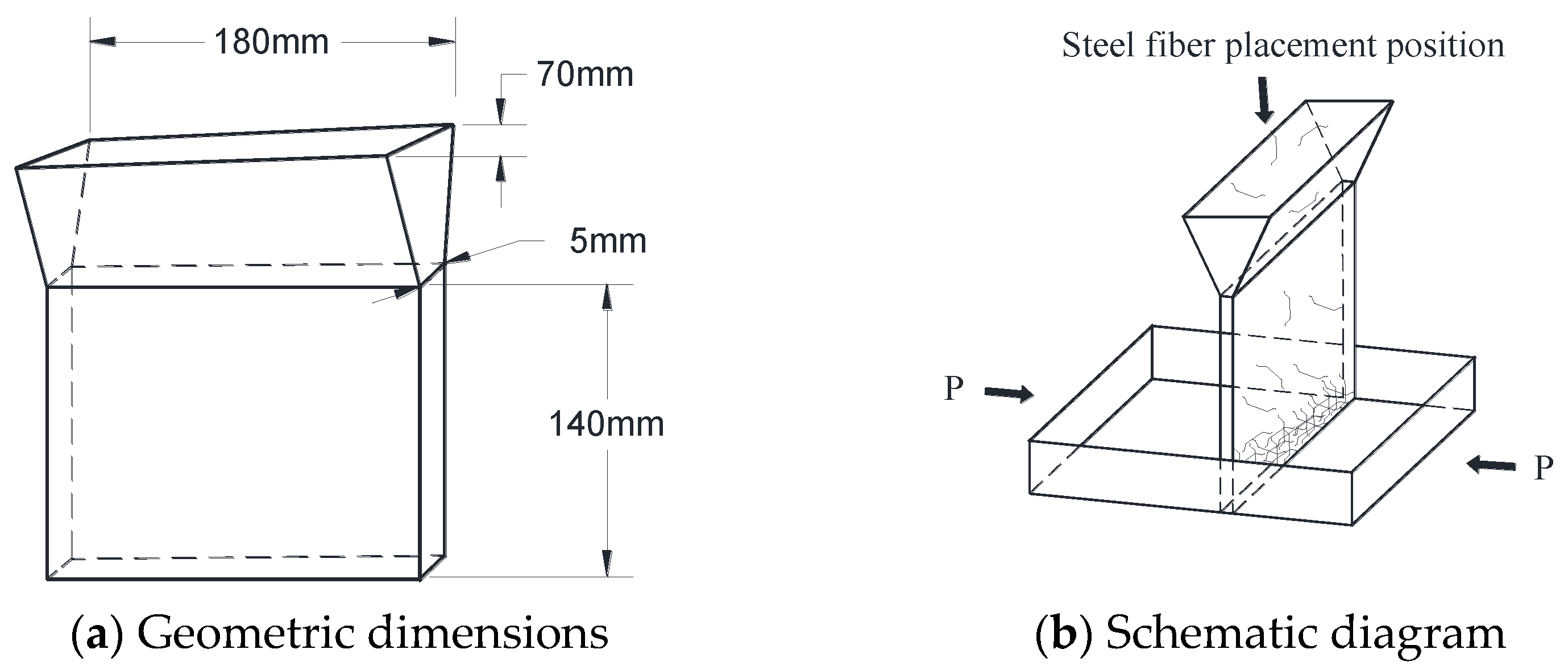
To achieve the directional placement of steel fibers, a custom-made, cost-effective device was developed in this study. The length of the device matches that of the mold, featuring a steel fiber placement port (upper port) measuring 180mm in length and 70 mm in width. The width gradually becomes narrower downward, reaching its narrowest point (5 mm) at one-third of the length of the device, maintaining this aperture for the remaining 140 mm extension, as depicted in Figure 2a. During device utilization, the narrow port aligns perpendicularly to the direction of the load, with the bottom of the mold aligned with the touch tool, as illustrated in Figure 2b. Fibers slide through the wide opening at an inclined angle into the narrow opening, eventually falling into the mold at free-fall speed. As the steel fiber descends through the inclined surface of the device from a height approximately five times the relative fiber length, it rotates freely in a two-dimensional direction during the descent. Subsequently, it intermingles randomly with the effect of gravity upon landing. The direction of steel fibers dropped by the device is essentially perpendicular to the load direction. Furthermore, due to the bent ends of the end-hooked fibers, this fiber placement method avoids fiber disconnection issues, promoting closer fiber connections with increased fiber placement. The device and the placed steel fibers are illustrated in Figure 3. It is noteworthy that while a small fraction of steel fibers may assume arbitrary directions through the custom-made device, the majority of steel fibers remain oriented perpendicular to the load direction.
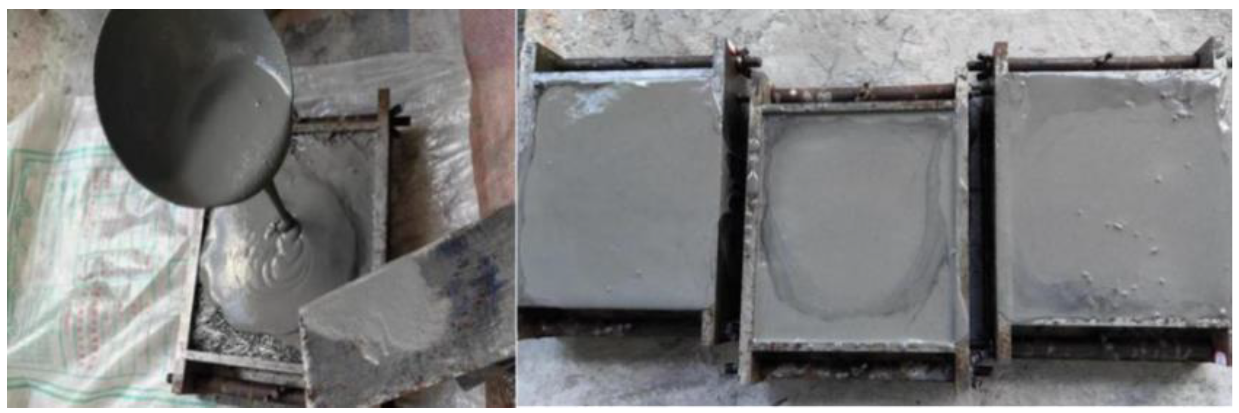
In this study, blocks measuring 180 mm × 70 mm × 200 mm were employed, a size commonly utilized in prior research [8,9,24,25,26,27,30,31,32,33]. Notably, the pouring process did not necessitate the use of a vibrating table due to variations in the filling properties of infiltration mortar corresponding to different fly ash substitution rates. Specifically, the SIFCON block with a fly ash substitution rate of 0% required placement on a vibrating table for vibration-assisted pouring, while the block with a fly ash substitution rate of 20% required slight vibration during pouring. Conversely, the block with a fly ash substitution rate of 40% could be poured without the need for a vibrating table, as depicted in Figure 4. Furthermore, to further study the impact of different steel fiber content and L/D ratios on the bearing capacity and ductility of SIFCON blocks, an orthogonal test design was employed. This design facilitated the creation of SIFCON blocks with different steel fiber content and L/D ratios, as detailed in Table 4. Each condition comprised three blocks, with steel fibers being directionally placed using the custom-made equipment developed in this study. For example, the specimen denoted as S-40%(F)-50-12% corresponds to a SIFCON block featuring a fly ash substitution rate (R) of 40%, a steel fiber aspect ratio (L/D) of 50, and a steel fiber volume fraction (Vf) of 12%. Additionally, to verify the efficacy of the custom-made steel fiber directional placement device, three SIFCON blocks were designed with a fly ash substitution rate of 20%, a steel fiber aspect ratio (L/D) of 50, and a steel fiber volume fraction of 12%. However, these blocks featured randomly distributed steel fibers and were labeled as S-40%(F)-50-12%-R.
As a large quantity of steel fibers is added into SIFCON, the cement mortar with enhanced fluidity is needed to effectively wrap the steel fibers during pouring. This ensures the compactness of SIFCON, leading to a more uniform dispersion of steel fibers. To assess the flowability of cement mortar under various fly ash substitution rates during pouring, this study employed the small slump flow and V-shaped funnel test [34,35,36,37], as illustrated in Figure 5. Additionally, the cubic compressive strength of cement mortar was measured using specimens of 100 mm × 100 mm × 100 mm. The results are presented in Table 5, wherein three specimens were tested for each fly ash substitution rate, and the provided cubic compressive strength represents the average of these three specimens.
Table 5 reveals that the addition of fly ash can effectively improve the fluidity of the mixture, but it will reduce the compressive strength of the material [10,38,39]. This phenomenon arises from the partial replacement of cement by fly ash, which possesses hydration characteristics distinct from those of cement. Fly ash has smaller particles with a larger specific surface area, leading to a relatively slower hydration reaction rate. While this reduction in viscosity contributes to improved fluidity, it also contributes to decreased material strength.

3. Compressive Bearing Capacity and Ductility of SIFCON Blocks

3.1. Compression Test of SIFCON Blocks

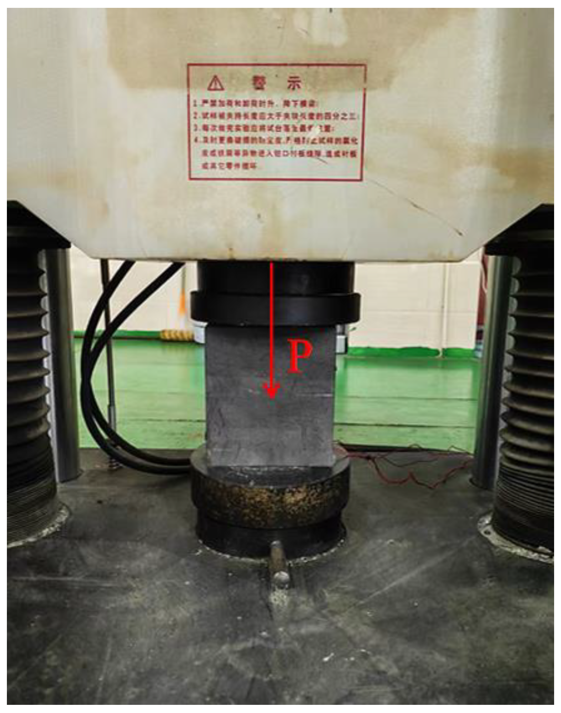
In this study, blocks measuring 200 mm in height, 180 mm in length, and 70 mm in width were subjected to axial compression testing using an electro-hydraulic servo hydraulic press. The test was conducted under displacement control mode at a rate of 0.3 mm/min. Throughout the test process, the load and displacement of the blocks were recorded using the acquisition system of the testing machine, as depicted in Figure 6.
During the testing of SIFCON blocks, three distinct damage patterns were observed, as shown in Figure 7. In the case of test blocks S-0%(F)-50-12% and S-40%(F)-33-12%, visible cracks emerged along diagonal planes, accompanied by lateral sliding of the upper and lower sections of the blocks along these lines, ultimately leading to shear damage. Conversely, for test blocks S-20%(F)-50-12%, S-40%(F)-50-10%, and S-40%(F)-70-12%, multiple fine cracks appeared on the surface, coupled with partial crushing, resulting in a combination of shear and localized crushing damage. In test blocks S-40%(F)-50-12% and S-40%(F)-50-14%, a uniform crushing damage pattern was observed. Notably, specimens exhibiting the third damage pattern demonstrated good ductility. Throughout the loading process, a faint and continuous sound of zipping was heard from the SIFCON blocks. This phenomenon can be attributed to the gradual extraction of steel fibers from the mortar matrix and the breakage of interconnections between fibers during compression. As the load increased, small cracks initially inhibited by steel fibers propagated further, causing disintegration of the mortar matrix. However, the interlocking steel fibers dispersed the main stress within crack through bonding with the matrix and linking between fibers, mitigating the propagation of cracks. As the test block continued to deform, more fibers were pulled out, and cracks expanded uniformly throughout its height. Although internal breakage occurred, the overall block did not fail suddenly, leading to uniform damage throughout the entire cross-section of the block.

3.2. Compressive Bearing Capacity of SIFCON Blocks

The compressive bearing capacity of each block is determined as the peak load achieved during the compression test. The peak strength (PS) is subsequently calculated by dividing the peak load (Pmax) by the cross-sectional area of the block (A). The corresponding test results are presented in Table 6, where 1, 2, and 3 denote the first, second, and third blocks under each condition, respectively. The “average” column represents the mean value obtained from the test results of the three blocks.
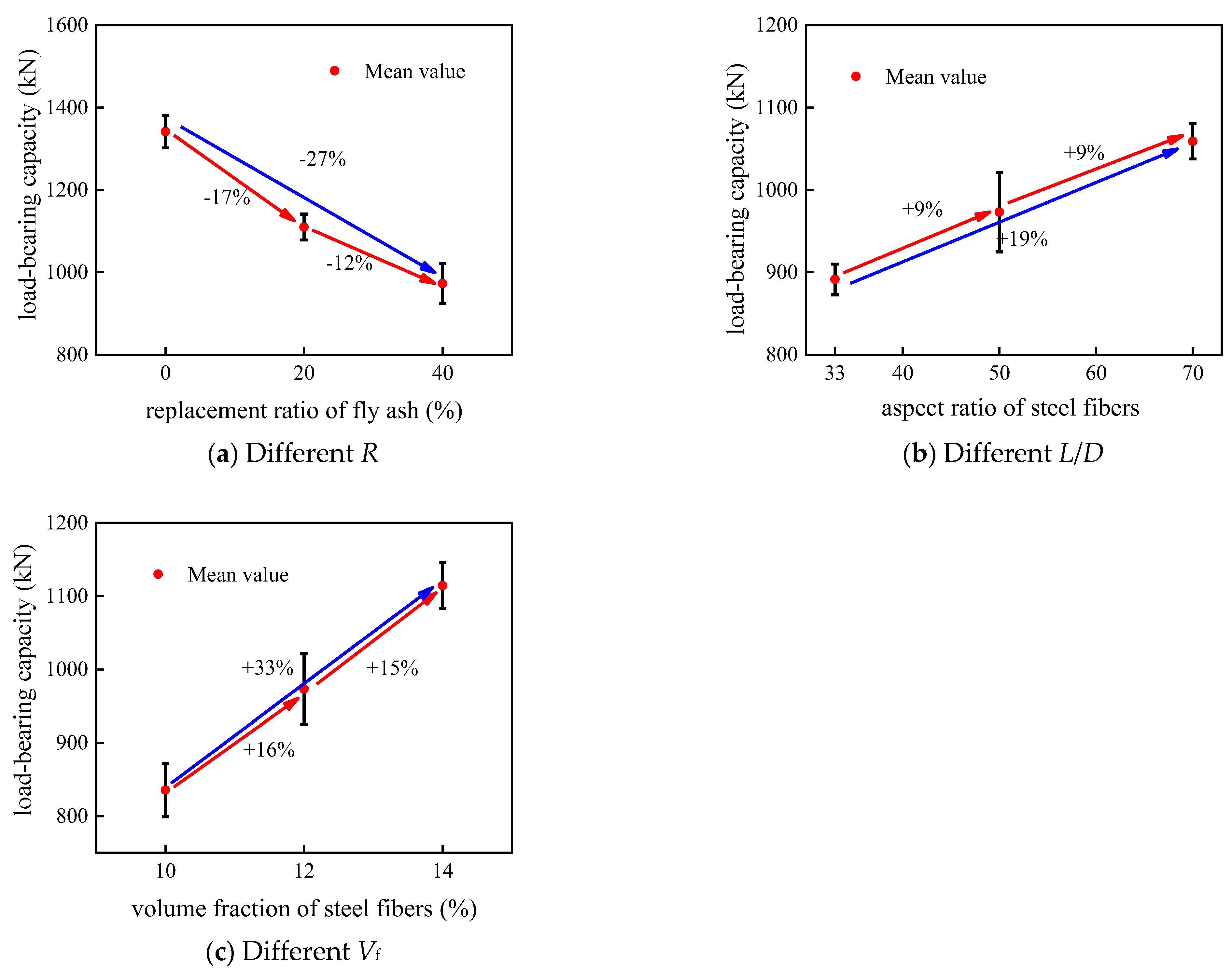
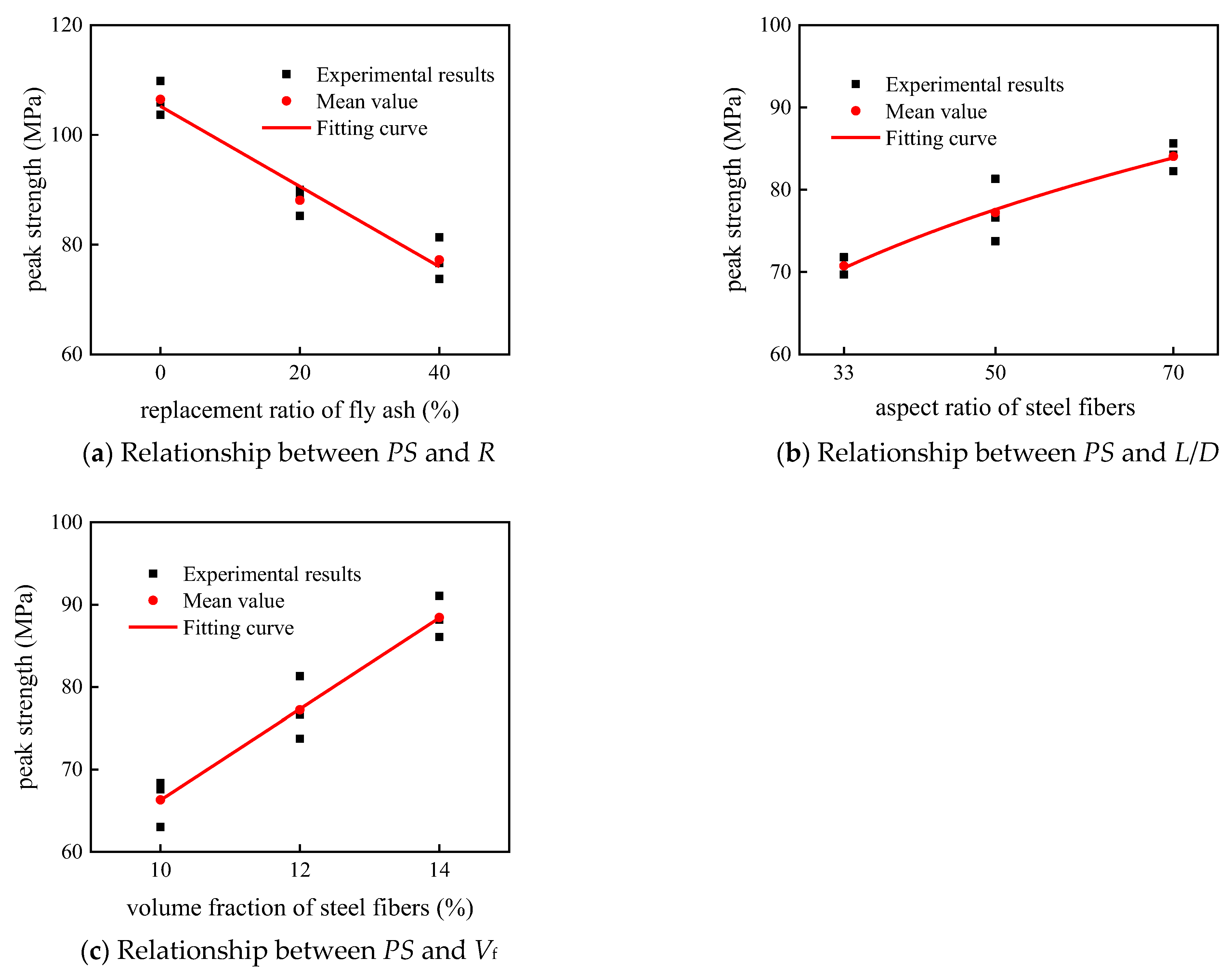
In order to investigate the influence of fly ash substitution rate, steel fiber aspect ratio, and steel fiber volume fraction on the bearing capacity of SIFCON blocks, the controlled variables are employed in this study. The effects of these factors on the bearing capacity of SIFCON blocks are illustrated in Figure 8, where (a) depicts blocks with different fly ash substitution rates but consistent steel fiber aspect ratio and volume fraction, namely, blocks S-0%(F)-50-12%, S-20%(F)-50-12%, and S-40%(F)-50-12%; (b) represents blocks with different steel fiber aspect ratios (L/D) but identical fly ash substitution rates and steel fiber volume fractions, specifically, blocks S-40%(F)-33-12%, S-40%(F)-50-12%, and S-40%(F)-70-12%; and (c) represents blocks with different steel fiber volume fractions but consistent fly ash substitution rates and steel fiber aspect ratios, namely, specimens S-40%(F)-50-10%, S-40%(F)-50-12%, and S-40%(F)-50-14%.
From Figure 8, it is evident that the addition of fly ash leads to a decrease in the bearing capacity of the blocks. Specifically, the bearing capacity of the blocks decreased by 31% as the fly ash substitution rate increased from 0% to 40%. Moreover, the bearing capacity of the blocks exhibited a notable increasing trend with the rise in both the steel fiber aspect ratio and the steel fiber volume fraction. The bearing capacity of the blocks increased by 19% as the steel fiber aspect ratio (L/D) increased from 33 to 70, while the bearing capacity of the blocks increased by 33% as the volume fraction of steel fibers increased from 10% to 14%. To further elucidate the trend of the effect of these three different factors on the load-bearing capacity of the blocks, the relationship between the peak strength of SIFCON blocks and the fly ash substitution ratio (R), steel fiber aspect ratio (L/D), and the volume fraction of steel fibers (Vf) is presented in Figure 9.
The magnitude of peak strength of SIFCON in Figure 9 reflects the bearing capacity of the block. From the figure, it is apparent that the load-bearing capacity of the block decreases linearly with an increase in the fly ash substitution rate. This decrease can be attributed to the addition of fly ash, which replaces a portion of the cement. It is likely that the slower and incomplete activation of fly ash during the early stages of hydration fails to fully exhibit its cementitious activity, thereby reducing the strength of the material. When the steel fiber aspect ratio (L/D) is 50 and the volume fraction of steel fibers (Vf) is 12%, the relationship between the peak strength of SIFCON specimens (PS) and the fly ash substitution rate (R) over the range of 0% to 40% can be expressed as follows:
P S = 105.22 0.73 R
The bearing capacity of SIFCON blocks increases as a power function of the steel fiber aspect ratio. This is attributed to the enhanced interaction between steel fibers with larger aspect ratios, which leads to better crack resistance within the material. Moreover, the bond between the fibers and the concrete strengthens with the increase in the steel fiber aspect ratio, thereby further enhancing the bearing capacity of the block. When the fly ash substitution rate (R) is 40% and the volume fraction of steel fibers (Vf) is 12%, the relationship between the peak strength (PS) of the SIFCON block and the steel fiber aspect ratio (L/D) over the range 33–70 is described by the following expression:
P S = 31.40 ( L D ) 0.23
The bearing capacity of SIFCON blocks exhibits a linear growth trend with increasing volume fraction of steel fibers. This is attributed to the inclusion of steel fibers, which prevents crack propagation and produces tensile resistance within the material. As a result, a portion of the energy generated during loading is absorbed by the steel fibers. Moreover, with higher volume fractions of steel fibers, the interfacial area between the fibers and concrete increases, enhancing bond performance and energy absorption capabilities. Consequently, the bearing capacity of the block increases. When the fly ash substitution rate (R) is 40% and the steel fiber aspect ratio (L/D) is 50, the relationship between peak strength (PS) and volume fraction of steel fibers (Vf) over the range of 10%–14% in SIFCON blocks can be expressed as follows:
P S = 58.33 + 0.31 e V f 3

3.3. Ductility of SIFCON Blocks

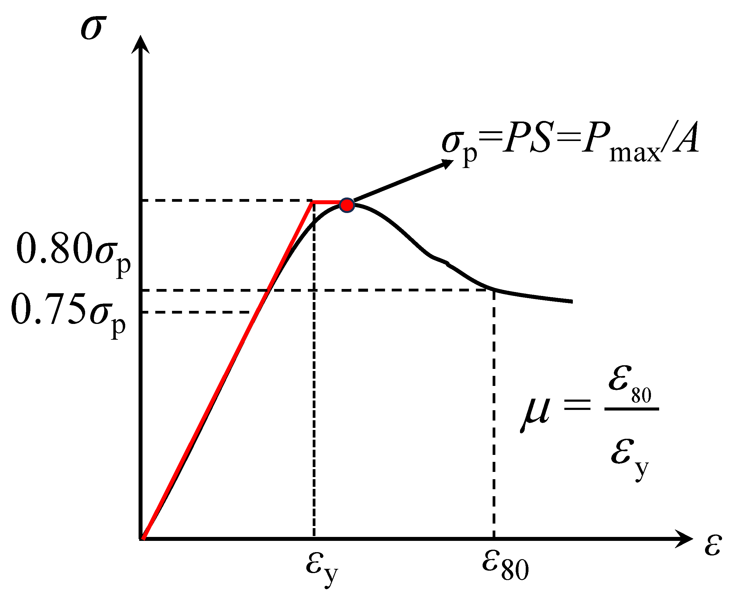
In this paper, ductility is assessed using the ductility ratio recommended by Huang et al. [13]. The expression for the ductility ratio (μ) is:
μ = ε 80 ε y
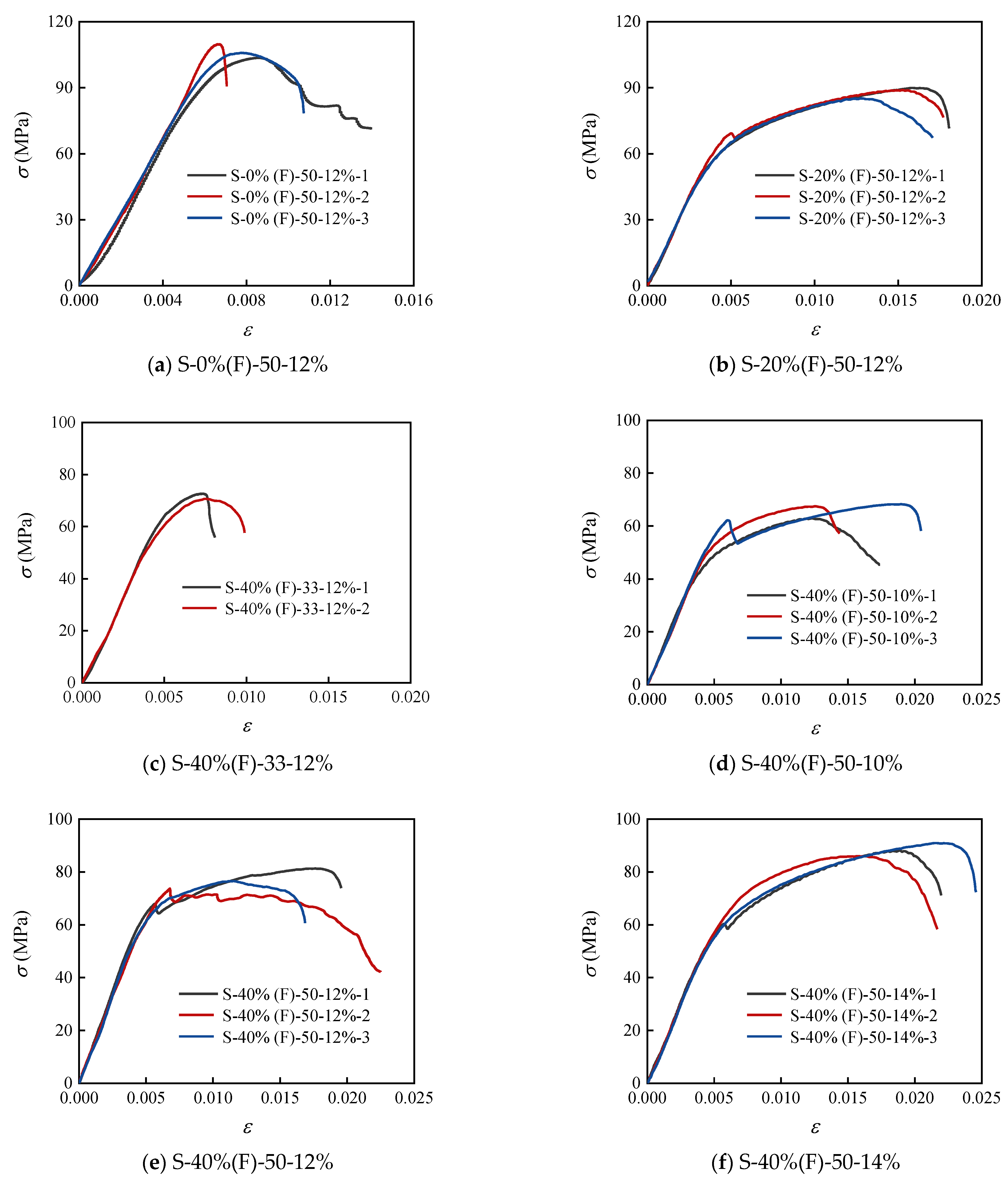
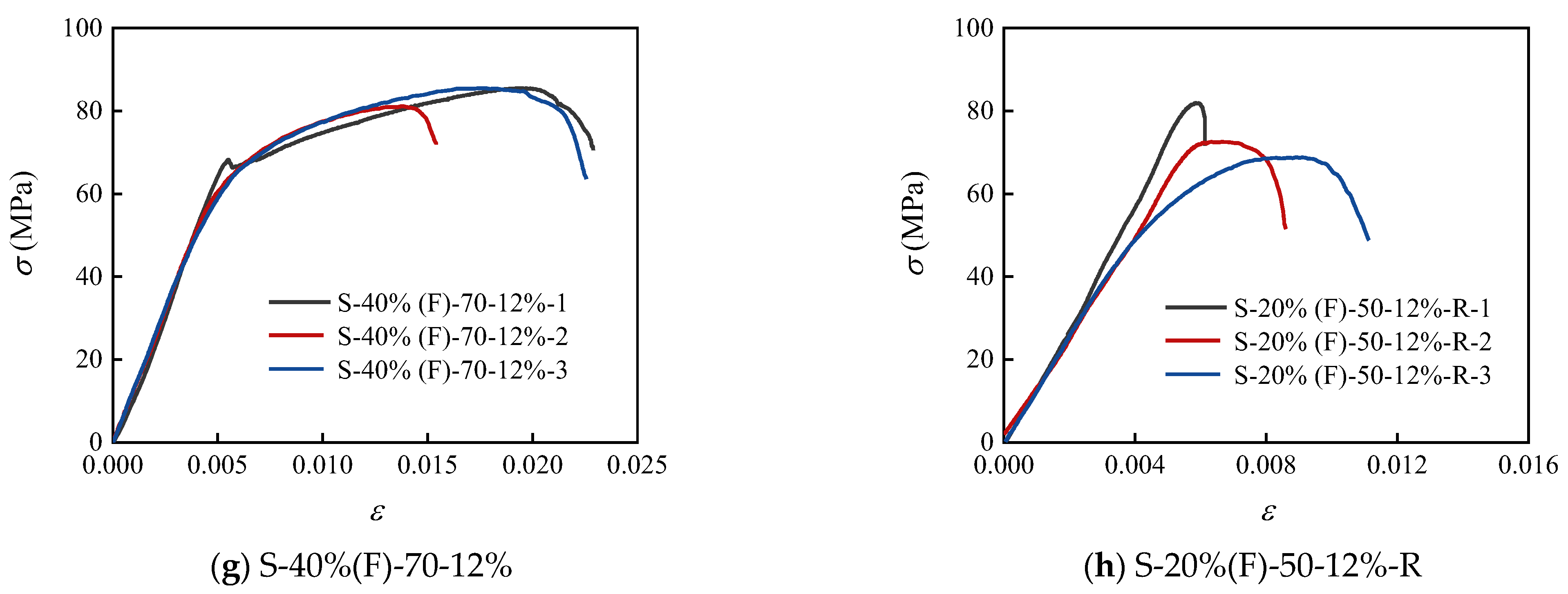
where ε80 is the strain corresponding to 80% of the ultimate stress on the descending section of the stress–strain curve (σε), while εy is the yield strain, which is the strain value corresponding to the intersection between the extension of the line connecting the origin of the stress–strain curve and the data point corresponding to 75% of the ultimate stress before the peak and the horizontal line extending from the ultimate stress. The values of ε80 and εy are calculated as shown in Figure 10. The stress–strain curve of the SIFCON block is depicted in Figure 11, and the corresponding ductility values are presented in Table 7, in which the strain gauge of the test block is obtained by dividing the displacement collected by the testing machine by the height of the specimen.
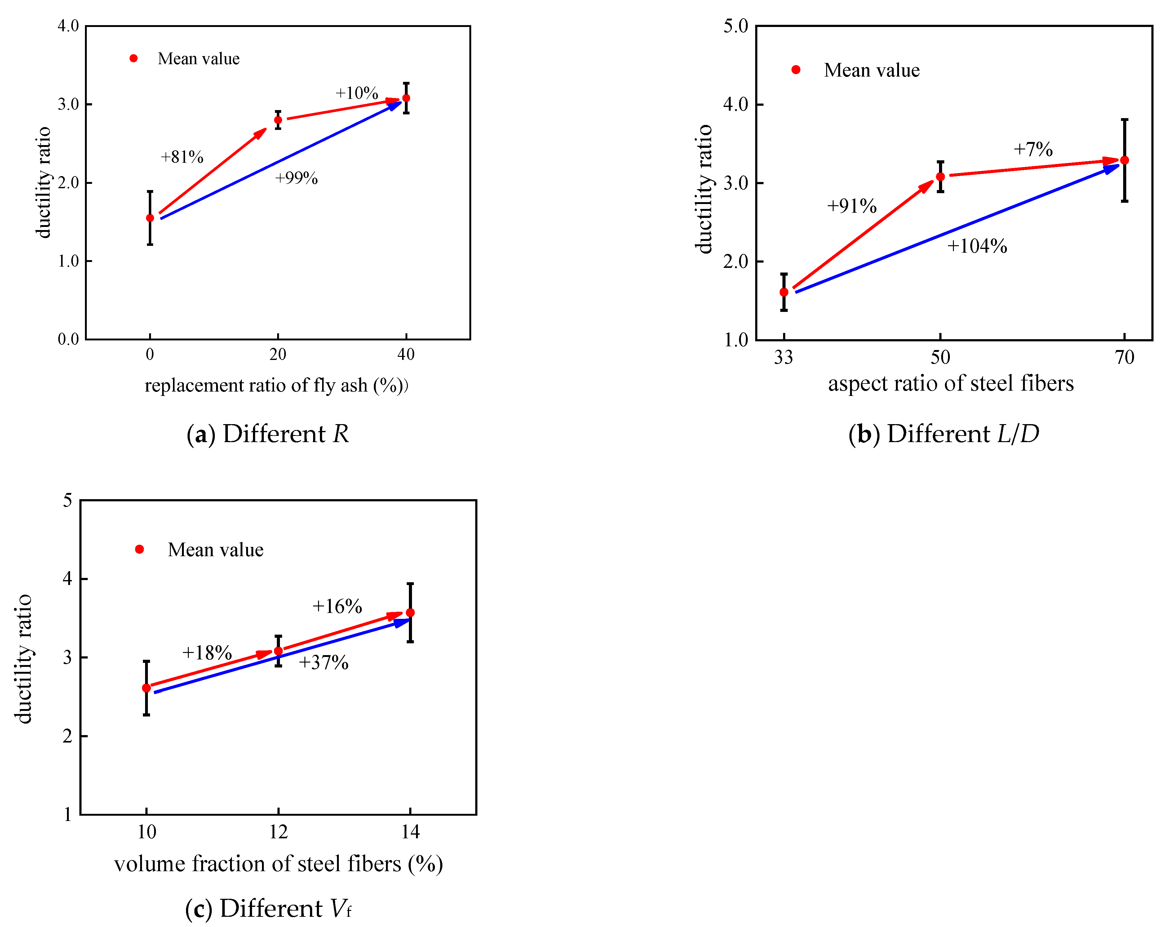
The influence of different factors on the ductility of SIFCON is depicted in Figure 12, with the test block numbers corresponding to those in Section 3.2 represented in (a), (b), and (c).
In Figure 12, it is evident that the addition of fly ash leads to a significant increase in the ductility of the blocks. Specifically, the ductility ratio of the blocks increased by 99% when the fly ash substitution rate rose from 0% to 40%. This improvement can be attributed to several factors. Firstly, the adhesion between the incompletely hydrated fly ash and the steel fibers is relatively weak. Additionally, the characteristic spherical particles of fly ash act as a lubricant between the steel fibers and the cement mortar, effectively reducing friction. Consequently, this lower chemical bond strength and interfacial friction strength minimized the risk of steel fiber fracture under load. This facilitated relative slip between the steel fibers and the hardened cement mortar, thereby enhancing the ductility of the SIFCON block. Meanwhile, the ductility of the blocks also exhibited a notable improvement trend with the increase in the steel fiber aspect ratio and the volume fraction of steel fibers. Specifically, the ductility ratio of the test blocks increased by 104% when the L/D ratio of the steel fiber increased from 33 to 70 and by 37% when the volume fraction of steel fibers rose from 10% to 14%. Notably, the ductility ratio of the SIFCON block with an L/D ratio of 33 was minimal. This might be attributed to the single-pour method used in this paper, where the steel fibers with an L/D ratio of 33 were not uniformly distributed throughout the molds. As a result, the block exhibited limited ductility upon reaching peak strength, with a speedy decrease in stress.

3.4. Rationality of the Custom-Made Steel Fiber Directional Placement Device

The analysis of the bearing capacity and ductility of SIFCON blocks with different steel fiber aspect ratios and volume fractions reveals that even with a steel fiber aspect ratio of 70 and a volume fraction of 14%, SIFCON blocks still exhibit high bearing capacity and good ductility. This observation reflects the effectiveness of the custom-made steel fiber directional placement device developed in this paper. To further demonstrate efficacy of the device in achieving directional distribution of steel fibers, Figure 13 presents the bearing capacity and ductility of SIFCON blocks with a fly ash substitution rate of 20%, a steel fiber aspect ratio of 50, and a steel fiber volume fraction of 12% under random distribution (without the device), denoted as S-20%(F)-50-12%-R, and directional distribution (with the device), denoted as S-20%(F)-50-12%. The bearing capacity and ductility ratio for both cases are compared.
Figure 13 clearly illustrates that the bearing capacity and ductility of SIFCON blocks with randomly distributed steel fibers exhibit more significant variability than those with directional distribution. This disparity arises from the difficulties in achieving a uniform distribution of randomly placed steel fibers within the blocks, resulting in inconsistent fiber content per unit volume and significant fluctuations in block performance. Moreover, the block S-20%(F)-50-12%-R demonstrates a higher bearing capacity and ductility ratio compared to the block S-20%(F)-50-12%, further confirming the efficacy of the device proposed in this paper for achieving directional placement of steel fibers and improving the construction method. This provides an empirical basis for the casting of fiber concrete.

4. Conclusions

This study introduces a custom-made steel fiber directional placement device for single pouring of SIFCON, optimizing the construction process. Through compressive tests, the impact of fly ash substitution rate, steel fiber aspect ratio, and volume fraction on SIFCON block properties was analyzed, leading to the following key conclusions:
(1)
The custom-made steel fiber directional placement device offers cost-effective customization and enhances the uniformity of steel fiber distribution. Those with directional placement exhibit superior bearing capacity and ductility ratios compared to blocks without the device.
(2)
The bearing capacity of SIFCON blocks shows a linear decline with increasing fly ash substitution rate. At the same time, it follows a power function with the rise in steel fiber aspect ratio and linear growth with higher steel fiber volume fractions. Notably, the bearing capacity diminishes by 31% when the fly ash substitution increases from 0% to 40%, while it increases by 19% and 33% with steel fiber aspect ratio increments from 33 to 70 and volume fraction increases from 10% to 14%, respectively.
(3)
The ductility of SIFCON blocks experiences significant enhancement with greater fly ash substitution rate, steel fiber aspect ratio, and volume fraction. The ductility ratio of the specimen increased by 99% when the fly ash substitution was increased from 0% to 40%, while ratios increase by 104% and 37% with aspect ratio increases from 33 to 70 and volume fraction increases from 10% to 14%, respectively.

5. Future Research

In the future, the custom-made equipment proposed in this study will be further developed and compared with existing technologies. Experimental research and comparative analysis of SIFCON properties with steel fibers in different distribution directions, not only perpendicular to the load direction, will be conducted. Additionally, the delivery device will be configured as multi-channel and will utilize external pressure to expedite the placement of steel fibers into the mold.

Author Contributions

Conceptualization, Z.W. and Y.Z.; methodology, Z.W. and Y.Z.; validation, Z.W., H.G. and Y.Z.; formal analysis, Z.W.; investigation, Z.W. and L.H.; resources, Y.Z. and H.G.; data curation, Y.Z. and H.G.; writing—original draft preparation, Z.W.; writing—review and editing, Z.W.; supervision, L.H. and H.G.; project administration, Y.Z. and H.G.; funding acquisition, Z.W., L.H. and H.G. All authors have read and agreed to the published version of the manuscript.

Funding

This research was funded by Key Science and Technology Plan Projects in Haikou City, Hainan Province, China, grant number: 2022-036.

Institutional Review Board Statement

Not applicable.

Informed Consent Statement

Not applicable.

Data Availability Statement

Data are contained within the article.

Conflicts of Interest

The authors declare no conflicts of interest.

References

  1. Kar, D.R.L. Properties, applications: Slurry infiltrated fiber concrete (SIFCON). Concr. Int. 1984, 6, 44–47. [Google Scholar]
  2. Homrich, J.R.; Naaman, A.E. Stress-strain properties of SIFCON in compression. ACI Mater. J. 1987, 105, 283–304. [Google Scholar]
  3. Naaman, A.E.; Homrich, J.R. Tensile stress-strain properties of SIFCON. Mater. J. 1989, 86, 244–251. [Google Scholar]
  4. Naaman, A.E.; Otter, D.; Najm, H. Elastic modulus of SIFCON in tension and compression. ACI Mater. J. 1992, 88, 603–613. [Google Scholar]
  5. Wu, Y.F. New avenue of achieving ductility for reinforced concrete members. J. Struct. Eng. 2006, 132, 1502–1506. [Google Scholar] [CrossRef]
  6. Liu, X.C.; Wu, Y.; Leung, A.; Hou, J. Mechanical Behavior of Mild Steel Compressive Yielding Blocks. In Proceedings of the First Asia-Pacific Conference on FRP in Structures, Hong Kong, China, 12–14 December 2007; pp. 12–14. [Google Scholar]
  7. Aravind, V.; Pradeepa, S. Experimental Study on Slurry Infiltrated Fibre Reinforced Concrete with Partial Replacement of Fly Ash. Int. J. Eng. Manag. Res. 2015, 5, 169–174. [Google Scholar]
  8. Preetha, R.; Joanna, P.; Rooby, J.; Pillai, C.S. Ductility behavior of reinforced high volume fly ash concrete beams. Int. J. Sci. Eng. Res. 2013, 4, 123–126. [Google Scholar]
  9. Liu, C.; Bi, Y.; Hua, Y. Mechanical Properties of PVA-ECC with High Volume Fly Ash and Mechanism Analysis of Fly Ash. Bull. Chin. Ceram. Soc. 2017, 36, 3739–3744. [Google Scholar]
  10. Elavarasi, D.; Mohan, K.S.R. Effect of fly ash on strength and durability of slurry infiltrated fibrous concrete. Rev. Romana Mater. 2018, 48, 529. [Google Scholar]
  11. Huang, J. Experimental Study on Mechanical Properties and Hydration Process of High Volume Fly Ash-Cement-Based Materials. Master’s Thesis, Zhejiang University of Technology, Hangzhou, China, 2020. [Google Scholar]
  12. Yıldızel, S.A.; Özkılıç, Y.O.; Bahrami, A.; Aksoylu, C.; Başaran, B.; Hakamy, A.; Arslan, M.H. Experimental investigation and analytical prediction of flexural behaviour of reinforced concrete beams with steel fibres extracted from waste tyres. Case Stud. Constr. Mater. 2023, 19, 02227. [Google Scholar] [CrossRef]
  13. Fayed, S.; Madenci, E.; Bahrami, A.; Özkiliç, Y.O.; Mansour, W. Experimental study on using recycled polyethylene terephthalate and steel fibers for improving behavior of RC columns. Case Stud. Constr. Mater. 2023, 19, 02344. [Google Scholar] [CrossRef]
  14. Özkılıç, Y.O.; Aksoylu, C.; Arslan, M.H. Experimental and numerical investigations of steel fiber reinforced concrete dapped-end purlins. J. Build. Eng. 2021, 36, 102119. [Google Scholar] [CrossRef]
  15. Tuyan, M.; Yazıcı, H. Pull-out behavior of single steel fiber from SIFCON matrix. Constr. Build. Mater. 2012, 35, 571–577. [Google Scholar] [CrossRef]
  16. Huang, Y.; Wu, Y.F. Ductility of Hybrid Fiber Reinforced Concrete. In Proceedings of the International Symposium on Innovation & Sustainability of Structures in Civil Engineering, Nanjing, China, 20–22 November 2005; pp. 20–22. [Google Scholar]
  17. Hamed, H.A.; Abass, Z.W. Effect of steel fiber proportion on SIFCON mechanical properties. J. Eng. Sustain. Dev. 2022, 26, 55–63. [Google Scholar] [CrossRef]
  18. Wood, B.T. Use of Slurry Infiltrated Fiber Concrete (SIFCON) in Hinge Regions of Earthquake Resistant Structures. Ph.D. Thesis, North Carolina State University, Raleigh, NC, USA, 2001. [Google Scholar]
  19. Abdollahi, B.; Bakhshi, M.; Mirzaee, Z.; Shekarchi, M.; Motavalli, M. SIFCON strengthening of concrete cylinders in comparison with conventional GFRP confinement method. Constr. Build. Mater. 2012, 36, 765–778. [Google Scholar] [CrossRef]
  20. Parameswaran, V.; Krishnamoorthy, T.; Balasubramanian, K.; Gangadar, S. Studies on slurry-infiltrated fibrous concrete (SIFCON). Transport. Res. Rec. 1993, 1382, 57–63. [Google Scholar]
  21. Lin, Z.W.; Shui, Z.H.; Yu, R.; Song, Q.L.; Xiao, X.G. Effect of Casting Method on Fiber Orientation and Distribution in Ultra-High Performance Fibre Reinforced Concrete (UHPFRC). Bull. Chin. Ceram. Soc. 2019, 38, 2010–2015. [Google Scholar]
  22. Huang, S.W.; Guo, Z.W.; Liu, X.F.; He, C.X.; Wang, H.; Duan, X.Z.; Bai, W.L.; Ben, H. Method for Directional Arrangement of Steel Fibers In Ultra-High Performance Concrete: China. Patent 110552508 A 2019. [Google Scholar]
  23. Mu, R.; Tian, W.L. Investigation on the preparation and properties of aligned steel fibre reinforced cement paste. J. Hebei Univ. Technol. 2012, 41, 101–104. [Google Scholar]
  24. Wu, Y.F.; Jiang, J.F.; Liu, K. Perforated SIFCON blocks-An extraordinarily ductile material ideal for use in compression yielding structural systems. Constr. Build. Mater. 2010, 24, 2454–2465. [Google Scholar] [CrossRef]
  25. Wu, Y.F.; Zhou, Y.W.; He, X.Q. Performance-based optimal design of compression-yielding FRP-reinforced concrete beams. Composite Struct. 2010, 93, 113–123. [Google Scholar] [CrossRef]
  26. Wu, Y.; Jiang, J.F.; Liu, K. Analysis and Design of Perforated SIFCON Blocks for Compression Yielding Structural Systems. In Proceedings of the Third Asia-Pacific Conference on FRP in Structures (APFIS 2012), Sapporo, Japan, 2–4 February 2012; International Institute for FRP in Construction: Sapporo, Japan, 2012; pp. 1–5. [Google Scholar]
  27. Liu, K. Experimental Study on the Ductility of SIFCON Blocks. Adv. Mater. Res. 2014, 838, 530–534. [Google Scholar] [CrossRef]
  28. GB 175-2020; General Portland Cement. China Standard Press: Beijing, China, 2020.
  29. GB/T 1596-2017; Fly Ash for Cement and Concrete. China Standard Press: Beijing, China, 2017.
  30. Liu, K.; Wu, Y.F. Compression yielding by SIFCON block for FRP-reinforced concrete beams. In Proceedings of the Asia-Pacific Conference on FRP in Structures, Hong Kong, China, 12–14 December 2007; Shatin Storage Book Collection: Hong Kong, China, 2007; p. 411. [Google Scholar]
  31. Zhou, Y.; Wu, Y.; Teng, J.; Leung, A. Ductility analysis of compression-yielding FRP-reinforced composite beams. Cem. Concr. Compos. 2009, 31, 682–691. [Google Scholar] [CrossRef]
  32. Zhou, Y.W.; Wu, Y.F.; Teng, J.G.; Leung, A.Y.T. Parametric space for the optimal design of compression-yielding FRP-reinforced concrete beams. Mater. Struct. 2010, 43, 81–97. [Google Scholar] [CrossRef]
  33. Zhou, Y.W.; Zhuang, L.; Hu, Z.; Hu, B.; Huang, X.; Zhu, Z. Perforated steel for realizing extraordinary ductility under compression: Testing and finite element modeling. Rev. Adv. Mater. Sci. 2022, 61, 195–207. [Google Scholar] [CrossRef]
  34. GB/T 50448-2015; Technical Specification for Application of Cement-Based Grouting Materials. China Standard Press: Beijing, China, 2015.
  35. Efnarc, F. Specification and guidelines for self-compacting concrete. Eur. Fed. Spec. Constr. Chem. Concrete Syst. 2002, 2, 1–28. [Google Scholar]
  36. Manolia, A.A.; Shakir, A.S.; Qais, J.F. The effect of fiber and mortar type on the freezing and thawing resistance of Slurry Infiltrated Fiber Concrete (SIFCON). In Proceedings of the IOP Conference on Materials Science and Engineering, Istanbul, Turkey, 8 August 2018; IOP: Suzhou, China, 2018; Volume 454, p. 012142. [Google Scholar]
  37. Li, H.; Li, Y.; Pan, Y.; Ng, P.L.; Leung, C.K.Y.; Zhao, X. Compressive properties of a novel slurry-infiltrated fiber concrete reinforced with arc-shaped steel fibers. J. Zhejiang Univ. Sci. A 2023, 24, 543–556. [Google Scholar] [CrossRef]
  38. Mehta, P.K. High-performance, high-volume fly ash concrete for sustainable development. In Proceedings of the International Workshop on Sustainable Development and Concrete Technology, Beijing, China, 20–21 May 2004; Iowa State University: Ames, IA, USA, 2004; pp. 3–14. [Google Scholar]
  39. Jau, W.C.; Fu, C.W.; Yang, C.T. Study of feasibility and mechanical properties for producing high-flowing concrete with recycled coarse aggregates. In Proceedings of the International Workshop on Sustainable Development and Concrete Technology, Beijing, China, 20–21 May 2004; pp. 89–102. [Google Scholar]
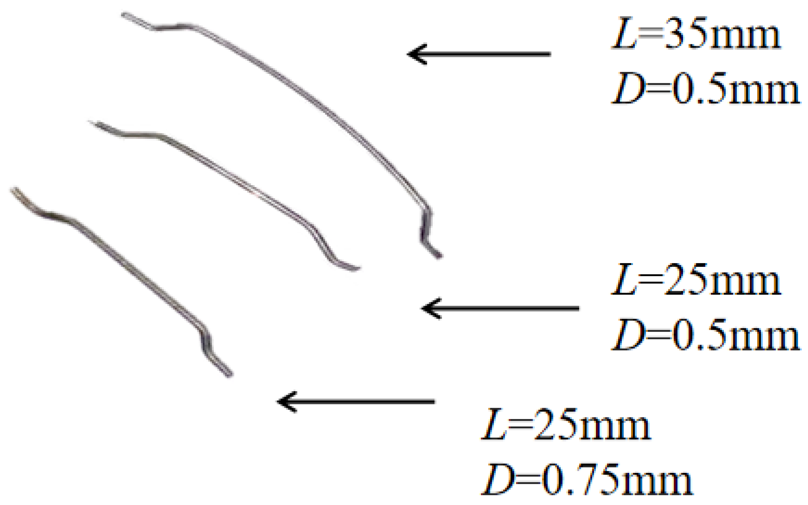
Figure 1. End-hooked steel fibers with different aspect ratios.
Buildings 14 02077 g001
Figure 2. Schematic diagram of custom-made directional steel fiber placement device.
Buildings 14 02077 g002
Figure 3. Custom-made device and placed steel fibers.
Buildings 14 02077 g003
Figure 4. Preparation of SIFCON test blocks.
Buildings 14 02077 g004
Figure 5. Small slump flow and V-shaped funnel test.
Buildings 14 02077 g005
Figure 6. Compression test of SIFCON block.
Buildings 14 02077 g006
Figure 7. Failure mode.
Buildings 14 02077 g007
Figure 8. Effect of different factors on the load−bearing capacity of SIFCON blocks.
Buildings 14 02077 g008
Figure 9. Peak strength of SIFCON blocks.
Buildings 14 02077 g009
Figure 10. Schematic stress–strain curve.
Buildings 14 02077 g010
Figure 11. Stress–strain curves of SIFCON blocks.
Buildings 14 02077 g011aBuildings 14 02077 g011b
Figure 12. Effect of different factors on the ductility ratio of SIFCON blocks.
Buildings 14 02077 g012
Figure 13. Effect of orientation of steel fibers on peak strength and ductility.
Buildings 14 02077 g013
Table 1. Physical properties of cement.
MaterialSpecific Surface Area (m2/kg)Initial Setting Time (min)Final Setting Time (min)Three-Day Flexural Strength (MPa)Three-Day Compressive Strength (MPa)Twenty-Eight-Day Flexural Strength (MPa)Twenty-Eight-Day Compressive Strength (MPa)
Cement3581722345.527.28.449
Table 2. Physical properties of fly ash.
MaterialFineness
(%)
Densities
(g/cm3)
Water Demand Ratio
(%)
Heat Loss Rate
(%)
Moisture Content
(%)
Fly ash10.82.391.54.60.5
Table 3. Physical properties of steel fiber.
Aspect
Ratio
L
(mm)
D
(mm)
Tensile Strength (MPa)Density (g/cm3)
33250.7511507.8
50250.5
70350.5
Table 4. Mix proportion of SIFCON blocks.
BlocksR (%)L/DVf (%)Number
S-0%(F)-50-12%050123
S-20%(F)-50-12%2050123
S-40%(F)-33-12%4033123
S-40%(F)-50-10%50103
S-40%(F)-50-12%123
S-40%(F)-50-14%143
S-40%(F)-70-12%70123
S-20%(F)-50-12%-R2050123
Table 5. Properties of cement mortar.
RMini Slump Flow
(mm)
V-Shaped Funnel
(s)
Mean Cubic Compressive Strength
(MPa)
0%2499.0856.33
20%2717.8750.17
40%3157.0243.02
Table 6. Compressive bearing capacity for SIFCON blocks.
Blocks-Compressive Bearing Capacity (kN)Peak Strength (MPa)
S-0%(F)-50-12%11306.12103.66
21383.98109.84
31334.59105.92
Mean1341.56106.47
Standard deviation39.403.13
S-20%(F)-50-12%11134.1390.01
21121.4089.00
31074.2885.26
Mean1109.9488.09
Standard deviation31.53 2.50
S-40%(F)-33-12%1904.6871.8
2878.2269.7
3**
Mean891.4570.75
Standard deviation18.71 1.48
S-40%(F)-50-10%1794.0563.02
2851.7667.60
3861.2168.35
Mean835.6766.32
Standard deviation36.36 2.89
S-40%(F)-50-12%11024.6381.32
2929.2573.75
3965.5476.63
Mean973.1477.23
Standard deviation48.14 3.82
S-40%(F)-50-14%11111.0788.18
21084.6186.08
31147.4891.07
Mean1114.3988.44
Standard deviation31.57 2.51
S-40%(F)-70-12%11061.8084.27
21036.4882.26
31079.0685.64
Mean1059.1184.06
Standard deviation21.42 1.70
S-20%(F)-50-12%-R11033.2082.00
2889.5670.60
3867.6468.86
Mean930.1373.82
Standard deviation89.93 7.14
* A SIFCON block that failed to be poured.
Table 7. Ductility ratio of SIFCON blocks.
Block-εy (10−3)ε80 (10−3)μ
S-0%(F)-50-12%16.1010.60 1.74
26.107.10 1.16
36.1010.70 1.75
Mean6.109.471.55
Standard deviation--0.34
S-20%(F)-50-12%16.3018.002.86
26.3018.102.87
36.4017.102.67
Mean6.3317.732.80
Standard deviation--0.11
S-40%(F)-33-12%15.508.001.45
25.609.901.77
3***
Mean5.558.951.61
Standard deviation--0.23
S-40%(F)-50-10%16.3016.202.57
26.3014.502.30
36.3018.702.97
Mean6.3016.472.61
Standard deviation--0.34
S-40%(F)-50-12%16.1119.203.14
26.1519.803.22
36.1117.502.86
Mean6.1218.833.08
Standard deviation--0.19
S-40%(F)-50-14%16.8922.503.27
26.9421.103.04
36.5324.603.77
Mean6.7922.733.57
Standard deviation--0.37
S-40%(F)-70-12%16.5422.903.50
26.1616.502.68
36.5323.803.64
Mean6.4121.073.29
Standard deviation--0.52
S-20%(F)-50-12%-R15.906.401.08
25.608.691.55
35.9611.201.88
Mean5.828.761.51
Standard deviation--0.40
* A SIFCON block that failed to be poured.
Disclaimer/Publisher’s Note: The statements, opinions and data contained in all publications are solely those of the individual author(s) and contributor(s) and not of MDPI and/or the editor(s). MDPI and/or the editor(s) disclaim responsibility for any injury to people or property resulting from any ideas, methods, instructions or products referred to in the content.