Article

Numerical Analysis of the Single-Directionally Misaligned Segment Behavior of Hydraulic TBM Tunnel

1
Xuchang Innovation Center of Intelligent Construction and Building Industrialization Technology, Zhongyuan Institute of Science and Technology, Zhengzhou 451400, China
2
Collaborative Innovation Center for Efficient Utilization of Water Resources, North China University of Water Resources and Electric Power, Zhengzhou 450046, China
3
Anyang Zhongzhou Water Supply Co., Ltd., Anyang 455000, China
*
Authors to whom correspondence should be addressed.
Buildings 2024, 14(7), 2198; https://doi.org/10.3390/buildings14072198
Submission received: 31 May 2024 / Revised: 12 July 2024 / Accepted: 15 July 2024 / Published: 16 July 2024
(This article belongs to the Special Issue Structural Analysis of Underground Space Construction)

Abstract

:
The misalignment of segments in installation is a common issue in the construction of TBM tunnels. This raises a question of whether misalignment affects the operation safety of a hydraulic TBM tunnel. Using a water transfer engineering project as an example, this paper built a three-dimensional finite element model composited with segment, grout layer and surrounding rock for the numerical analysis of the behavior of single-directionally misaligned segments. The crown or invert segment was separately misaligned towards to the center of segment ring in a value of 5 mm, 10 mm, 20 mm, 30 mm or 40 mm. The strength grade of the segment concrete was C50. A weaker surrounding rock composed of V-class rock was considered for the tunnel. The results indicate that the misalignment of the crown or invert segment, respectively, creates the tensile stress in the inner surface of the corresponding segment, the tensile stress will be over the limit of C50 concrete when the misalignment is over 30 mm, indicating a risk of concrete cracking. The contact surfaces of the segment ring basically remain in compression, and the locating pins between the segment rings exhibit an evident increase in tensile stress at misaligned positions. The key points that can be obtained from this study are that a special supervision is needed to ensure the accuracy of segment installation, and strengthening measures are needed for existing misaligned segments.

1. Introduction

In contemporary social development, long-distance hydraulic tunnels are indispensable for managing and distributing water resources for dwellings, industry and agriculture [1,2]. In regions characterized by mountainous terrain, the construction of hydraulic tunnels often encounters intricate geological conditions which surpasses the capabilities of traditional methods, thereby necessitating the employment of sophisticated tunnel boring machine (TBM) technology [3,4,5]. This raises doubt about the TBM’s efficiency, which is hinged significantly on the structural reliability and stability of the tunnels. Due to the complexity of construction conditions, the impact factors not only come from the TBM itself, including the cutterhead wear, excavating attitude and thrust and jack compression on segments, but also come from surrounding conditions, including rock, underground water, adjacent structures and labor technics [6]. A common phenomenon is concerned about the misalignment between adjacent segments, which is normally caused by manufacturing discrepancies, assembly errors and the unavoidable initial misalignment in the shield process. Although the misalignment does not immediately threaten construction safety, it may adversely affect the operational safety of the tunnel, due to the alterations in the loading and unloading of the surrounding rock, nearby excavations or other activities [7,8]. This leads to the escalation of complexity and the increase in financial burden associated with the maintenance and repair of shield tunnels [9].
Numerical and experimental research has been performed on the load-bearing characteristics of hydraulic tunnels under external stresses. A half-plane time-domain boundary element method was applied to obtain the seismic ground response of tunnels [10,11]. An integrated model was formulated for a small-diameter hydraulic tunnel, which included surrounding rock, grouting and segments [12,13]; the results indicated that the stress and deformation of the segment lining are minimal during construction, with primary stresses concentrated near the joints. A semi-analytical solution was proposed to determine the ultimate load-bearing capacity of directly spliced tunnel linings [14], concentrating on the stress and deformation experienced by the linings under various vertical load cases. An analytical model was introduced, which aimed to assess the mechanical responses of shield tunnels subjected to ground fault displacements, while a large-scale model test was conducted to investigate the deformation and failure modes of tunnel structures amidst fault ruptures [15]. A full-scale test model was conducted to study the deformation and failure patterns of tunnel structures under extreme loading conditions [16]. A comprehensive three-dimensional model was developed to analyze portal structures in hydraulic tunnels, identifying potential damage modes and exploring their mechanisms [17]. In fact, a finite element model (FEM) has been specified in codes for the design and analysis of non-rods structures, including massive concrete structures and shield tunnels [18,19].
The statistical analyses have highlighted the fact that deviations in segment assembly are primary contributors to tunnel damage before construction is completed [20,21]. Common defects identified during the installation of tunnel linings are misalignments and gaps between segments [22]. Using full-scale model tests to examine the initial deformation of a tunnel [23], convergence changes were measured to gain insights into the lateral mechanical response of a misaligned shield tunnel that was impacted by unloading from neighboring excavation sites. The investigations into cracks and misalignments in the tunnel segments revealed that these issues predominantly arise from delays in backfilling with peastone grouting after installation [24]. These prevalent misalignments, classified into longitudinal and ring joint types, not only cause localized problems such as longitudinal cracks, corner drop-offs and water leakage but also change the internal force distribution within the entire tunnel ring, resulting in stress concentrations [25,26,27]. The stress concentration has significant implications on the failure mode of the tunnel lining, critically affecting the structure’s safety and durability [28]. From a mechanical standpoint, when identifying the causes of segment misalignment, the buoyancy exerted by synchronous grouting fluid around the segments is a frequent factor; the misalignment commonly occurs at the crown and the invert segments [29]. The statistical analysis of segment misalignment during construction showed that misalignments significantly affect structural stress and primarily cause longitudinal cracking [30]. From the study of shield tunnels with segment misalignment, significant alterations in the internal forces of structure were found following the initial segment misalignment [31]. Full-scale tests and simulations revealed that excessive bolt pressure and asymmetrical stress in misaligned tunnel segments led to joint damage and distinct crack patterns under various support conditions [32,33]. This highlights the importance of investigating the effects of misalignment on the load-bearing capacities of hydraulic tunnel structures.
Therefore, tunnel segment misalignment is an issue that should be researched to identify the causes and types of misalignments, along with examining the local mechanical properties of the affected segments. Despite the above efforts reported in the literatures, there is a lack of a comprehensive analysis of a single-directionally misaligned segment on the structural load-bearing performance of the tunnel. In this respect, this study aims to bridge this gap by employing three-dimensional (3D) FEM to investigate the effects of prevalent misalignment forms on the load-bearing capacities of tunnel structures. In view of the fact that weak rock exerts significant surrounding pressure on segment lining, the V-class surrounding rock was considered in this study. The circumferential stress of segments, the segment contact stress and the locating pin stress were analyzed to identify the worst status of segment lining. The results provide an examination of the mechanical properties of segment lining with misalignment defects and valuable guidance for controlling the construction quality of the segment lining of hydraulic tunnels.

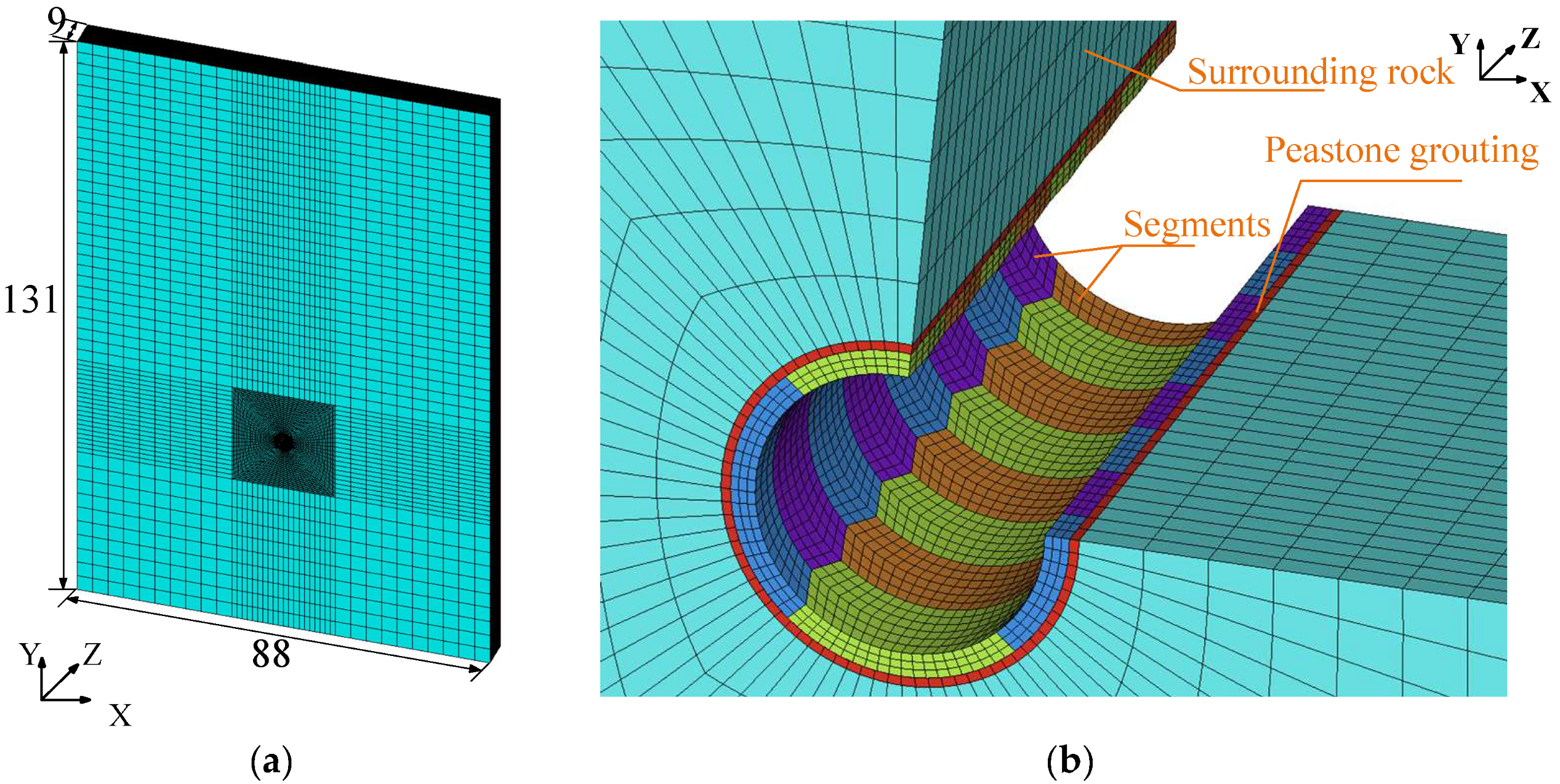
2. 3D FEM for Numerical Analysis

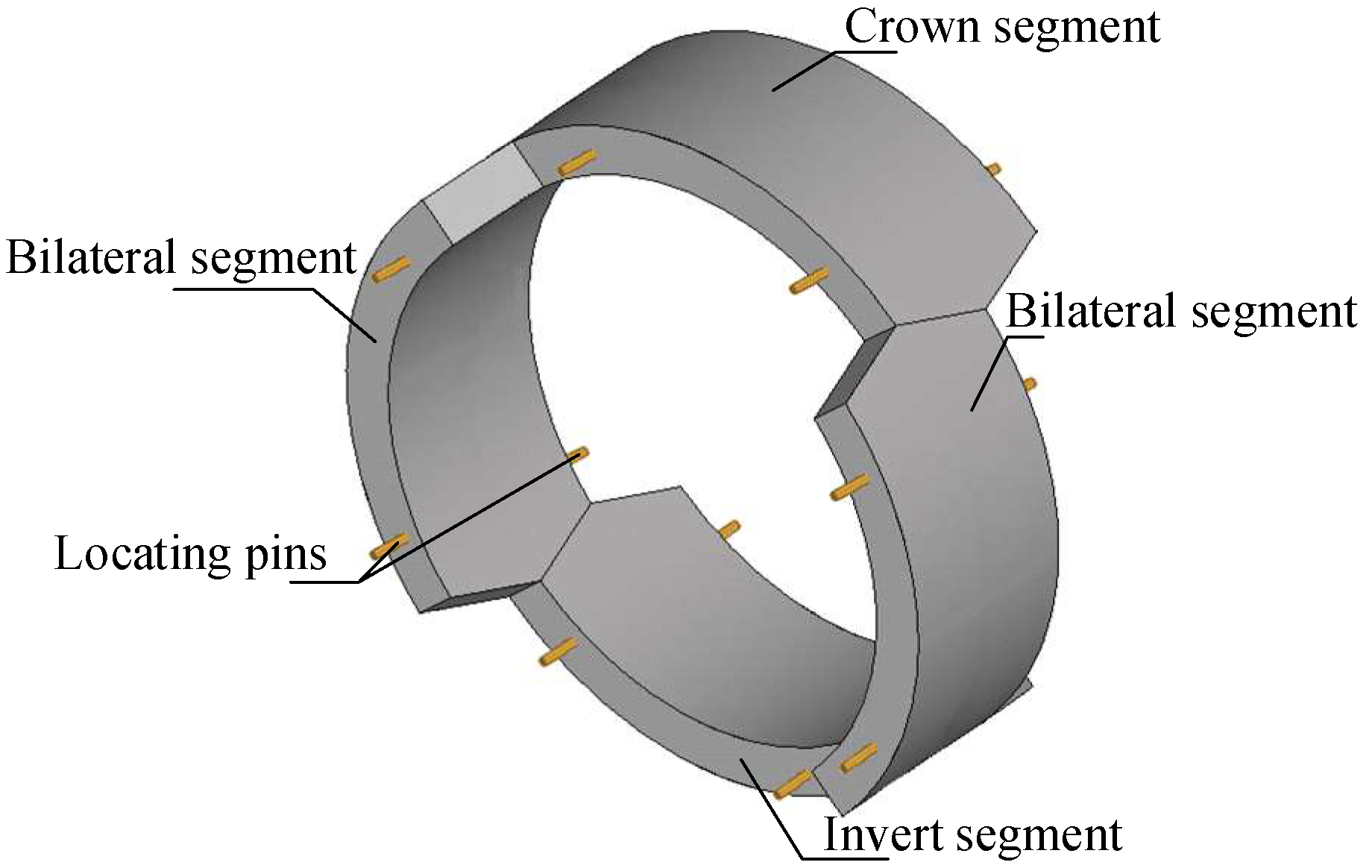
2.1. Composition of Segment Lining

According to the design document for the hydraulic tunnel for Anyang City’s West Route of the South-to-North Water Diversion Project, the segments of shield tunnel are made of C50W8F100 concrete. Figure 1 illustrates the segment assembly of the tunnel. Each ring of the segment lining consists of four hexagonal honeycomb-shaped segments, and the adjacent segments are connected by two locating pins in the ring joints. No protrusions are used on the contact surfaces of the ring and the longitudinal joints of the segments.

2.2. Composition of Segment Lining

With the aid of ANSYS 17.0 finite-element software, the coordinates of the 3D FEM of the segment lining were set as the X-axis for the transverse horizontal direction of the tunnel section, the Y-axis for the transverse vertical direction of the tunnel section and the Z-axis for the longitudinal direction along the tunnel. The boundary was determined with a distance from the lining no less than 8–10 times that of the tunnel diameter [34,35]. As shown in Figure 2a, the entire 3D FEM was built with the origin coordinate being the sectional center of the tunnel. The vertical boundary and the bottom boundary were 44 m from the center. The top boundary was the ground surface, which was selected at a poor geological condition with V-class rock, and the average burial depth was 87 m for the tunnel.
To build the 3D FEM, the mesh of the surrounding rock was first divided to simulate the initial excavation to achieve a stress equilibrium. Then, the peastone grouting, the segment lining and the locating pins were successively established, as shown in Figure 2b. The normal constraints were set on the vertical boundaries, and the fixed constraints were set in all three directions at the bottom boundary. Because this study involves quasi-static analysis, seven segment rings were established to eliminate boundary effects. The middle ring of segments was intended to give the analytical results. The segments, peastone grouting and surrounding rocks were simulated using SOLID45 elements, while the locating pins were simulated using BEAM188 elements. To achieve higher accuracy when analyzing complex geometries, all meshes were divided using mapped hexahedral elements. The surrounding rock within a 4 m radius of the tunnel was more finely meshed to ensure precise computational results. The misalignment defects of the segments were simulated by applying enforced displacement to the segments. The gaps generated by the enforced displacement were managed using element management options, ensuring that the gaps were filled with peastone grouting. The grooves between the segment contacts were simplified to planar contacts with an applied friction coefficient to simulate the behavior of the contact surfaces. The contact was established using TARGE170 target elements, which described the 3D target surfaces for contact with the CONTA173 elements. The CONTA173 contact elements were 4-node surface-to-surface contact elements, which described the contact and sliding conditions between the TARGE170 target elements and the deformable surfaces defined by these elements [36,37,38].

2.3. Constitutive Relationships

The constitutive relationships among the segment concrete, peastone grouting and locating pins were set as the linear elastic, with the main parameters shown in Table 1. The Mohr–Coulomb constitutive model was used for the surrounding rock, with the main parameters shown in Table 2. The interfaces between the segments and the surrounding rock and those between the segments were set as face-to-face contacts, which complied with Coulomb’s law of friction along the tangent direction. When the tangential stress reached a critical value, a slipping was created with a friction coefficient of 0.5 [39]. A hard contact was applied to the normal direction of the interfaces, which was allowed to separate.

2.4. Working Conditions

Based on empirical knowledge and findings from the related literature on segment misalignment [29,30], the most prevalent forms of segment misalignment during the installation process were crown or invert segment misalignments. These are classified as single-directionally misaligned segments, as depicted in Figure 3.
In the acceptance reports for these two types of segment misalignments, the maximum misalignment was found to be 30 mm. Due to the complexity and unpredictability of tunnel structures, segment misalignments may exceed the acceptance criteria. To explore the stress variation trends in misaligned segment structures, the maximum segment misalignment was set as 40 mm. To investigate the effects of different amounts of misalignment, the single-directional misalignment was set as 5 mm, 10 mm, 20 mm, 30 mm or 40 mm, along with a no-defect case as a comparison. The specific conditions are shown in Table 3.

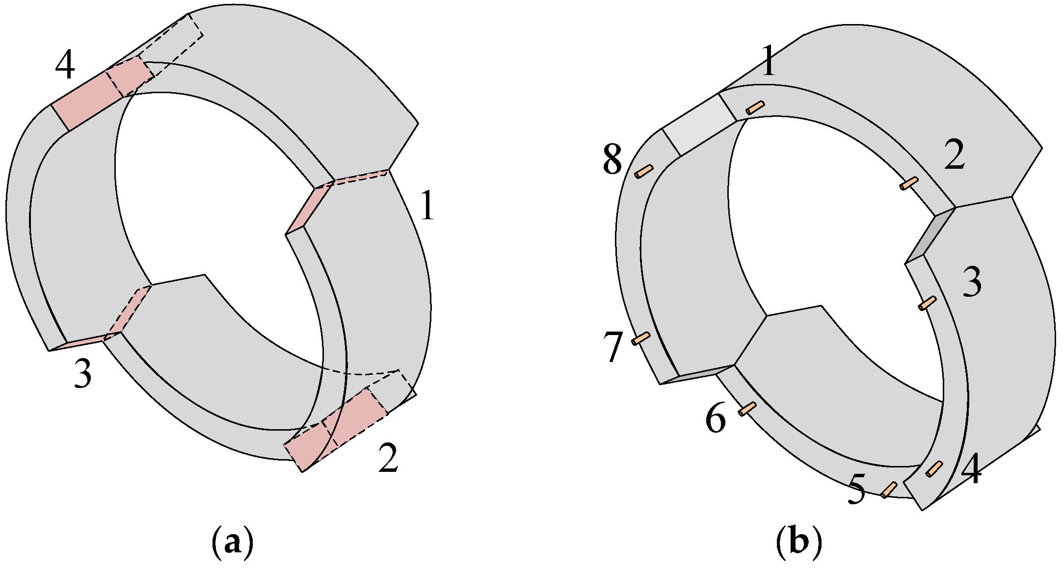
2.5. Analytical Locations of the Segment Lining

When a misalignment exists in a segment lining, the failure of the segment lining will occur if the compressive stress is over the compressive strength of the segment concrete or the misalignment enlarges to break away from the contact of the segments. Otherwise, cracks may appear on segments if the tensile stress is over the tensile strength of the segment concrete. Because the shield tunnel mainly bears the vertical load of the surrounding rock, in order to reduce the influence of boundary effects on the analytical results, the middle ring of the segment lining along the longitudinal direction of the 3D FEM was selected as the analytical object after the misalignment defects were exerted. The middle cross-section of the middle ring segment was selected to analyze the circumferential stress, from which 360 pairs of circumferential stresses were extracted at different angles. The contact surfaces of the misaligned segment were selected to analyze the contact performance, which were numbered 1 to 4, as shown in Figure 4a. Meanwhile, the locating pins numbered 1 to 8, as shown in Figure 4b, were selected to analyze the bearing performance of the locating pins.

3. Results, Analysis and Discussion

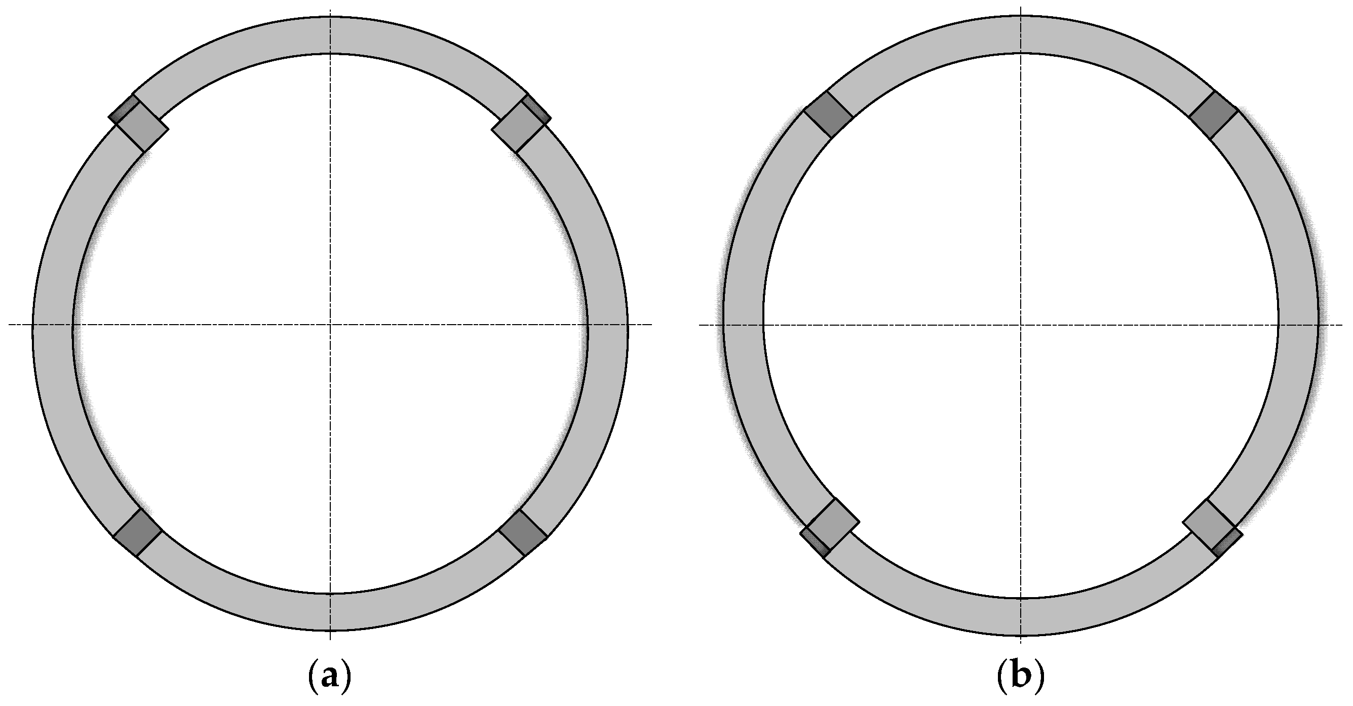
3.1. Misaligned Crown Segment

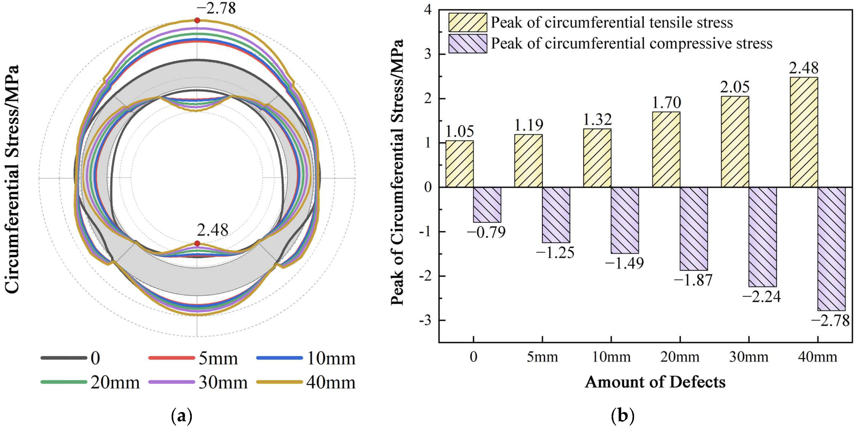
3.1.1. Circumferential Stress of Segment

The circumferential stresses on the inner and outer layers of the middle cross-section of the misaligned ring segment are depicted in Figure 5a. It is defined that the direction toward the center of the segment is tensile stress (positive), and the outward direction is compressive stress (negative). The peak values of circumferential stress on the inner and outer layers are illustrated in Figure 5b. In the case of no defect, the stress and deformation of the segment ring is similar to existing studies [6,12], with the inner layer of both crown and invert segments experiencing tension and the inner layer of the invert segment experiencing the highest tensile stress. This demonstrates the reliability of the FEM analytical results of this study. Because the V-class rock is lower in strength, which mainly produces vertical pressure transmitted through the grout layer on the crown segment, it causes a bending effect on the crown and invert segments, with the character of outer side compression and inner side tension.
With the increase in the misalignment of the crown segment, both the inner circumferential tensile stress and the outer circumferential compressive stress at the crown position exhibit a continuous increase tendency. The peak values of these stresses across the entire ring segment are consistently found at the middle of the crown of the misaligned segment ring. As shown in Figure 5b, the maximum tensile and compressive stresses of segment ring without misalignment are 1.05 MPa and −0.79 MPa, respectively. With a 40 mm misalignment of the crown segment, these stresses respectively escalate to 2.60 MPa and −2.72 MPa. The increments in maximum tensile stress under various conditions are 17%, 9%, 22%, 25% and 28%, while those for maximum compressive stress are 61%, 9%, 20%, 25% and 30%, respectively. Considering that the tensile stress limit of C50 concrete is 0.85 times that of the tensile strength, i.e., 0.85 × 2.64 MPa = 2.24 MPa [18], the tensile stress of 2.60 MPa is over the limit at the maximum crown segment misalignment. This means a substantial risk of cracking. Notably, the tensile stress of 2.03 MPa at a 30 mm segment misalignment also reaches 90.6% of the limit stress, indicating a high potential for cracking. Therefore, the segment lining exhibits a higher tolerance for compressive stresses, while tensile stress emerges as a critical factor in the potential for structural failure with the presence of crown segment misalignment.

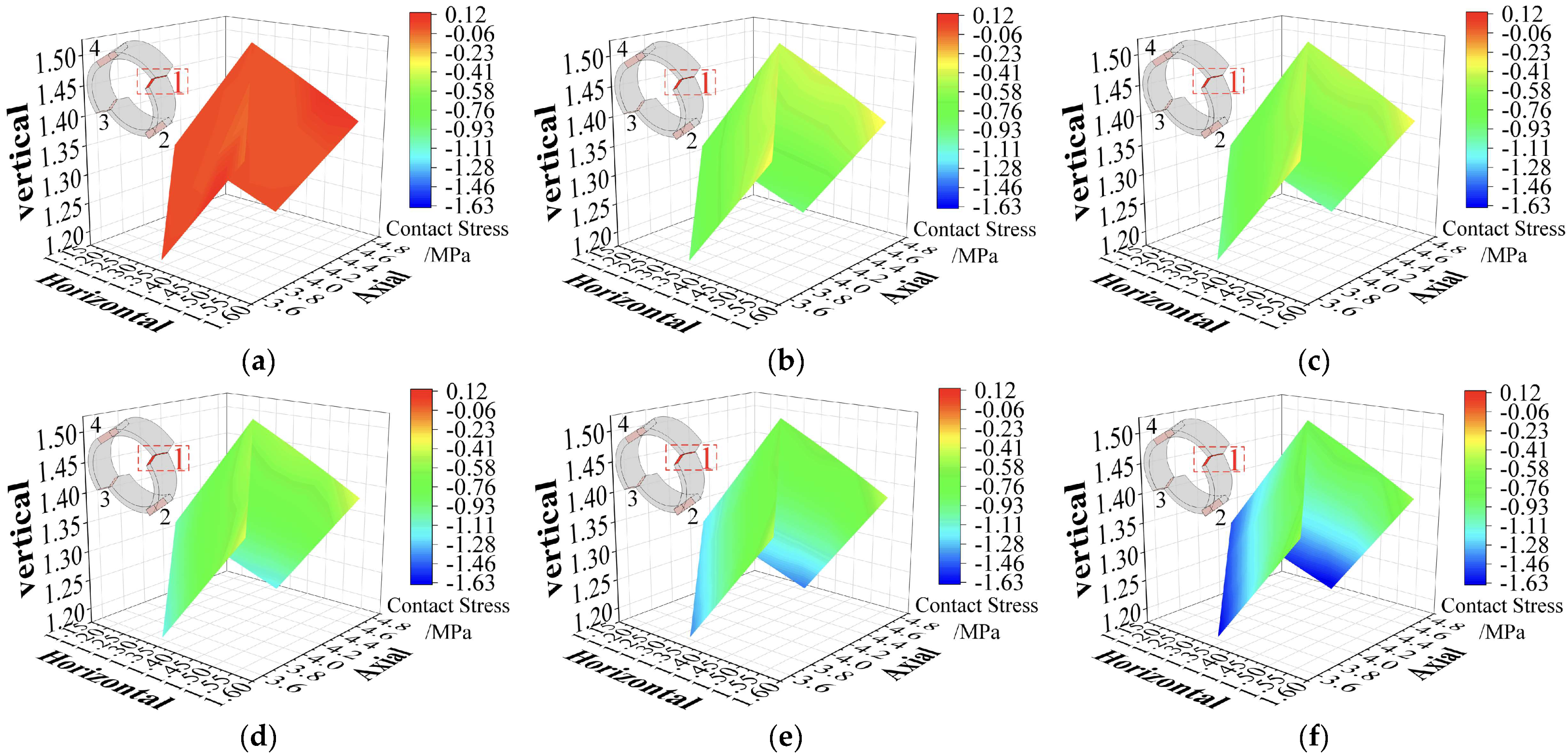
3.1.2. Segment Contact Stress

Given the symmetrical assembly of the tunnel segments in this study, the contact stresses are likewise symmetrical. Thus, the analysis is confined to the right-hand contact surfaces, namely, contact surfaces 1 and 2. Figure 6 and Figure 7 illustrate the contact surface stress distribution on contact surfaces 1 and 2 in the cases of different crown segment misalignments.
The FEM analysis of contact stresses on the segments without misalignment defects reveals that all joint surfaces are in normal contact, with the contact surfaces primarily transmitting compressive forces. The invert segment must endure the load transferred from the above segments, resulting in higher compressive stress on contact surface 2 than on contact surface 1. The peak compressive stresses on contact surfaces 1 and 2 are 0.62 MPa and 0.78 MPa, respectively.
When a crown segment misalignment defect occurs, the crown segment fails to properly align with the adjacent side segments, resulting in an uneven force distribution at the site of the misalignment. As the misalignment level increases, the pressure on contact surface 1 also escalates. These defects primarily transfer loads from the interior of the segment to the invert segment, thereby increasing the pressure on contact surface 2 as the misalignment intensifies. At the maximum misalignment of 40 mm, the peak tensile stress on contact surface 1 reaches 0.71 MPa, while the maximum compressive stress reaches −1.73 MPa. Similarly, on contact surface 2, the peak tensile stress is 0.40 MPa, and the maximum compressive stress is −1.07 MPa. Despite these stress increases, the stresses on the contact surfaces remain within the design standard values, and no failure phenomenon is observed, indicating that the structure maintains its integrity even under such conditions.

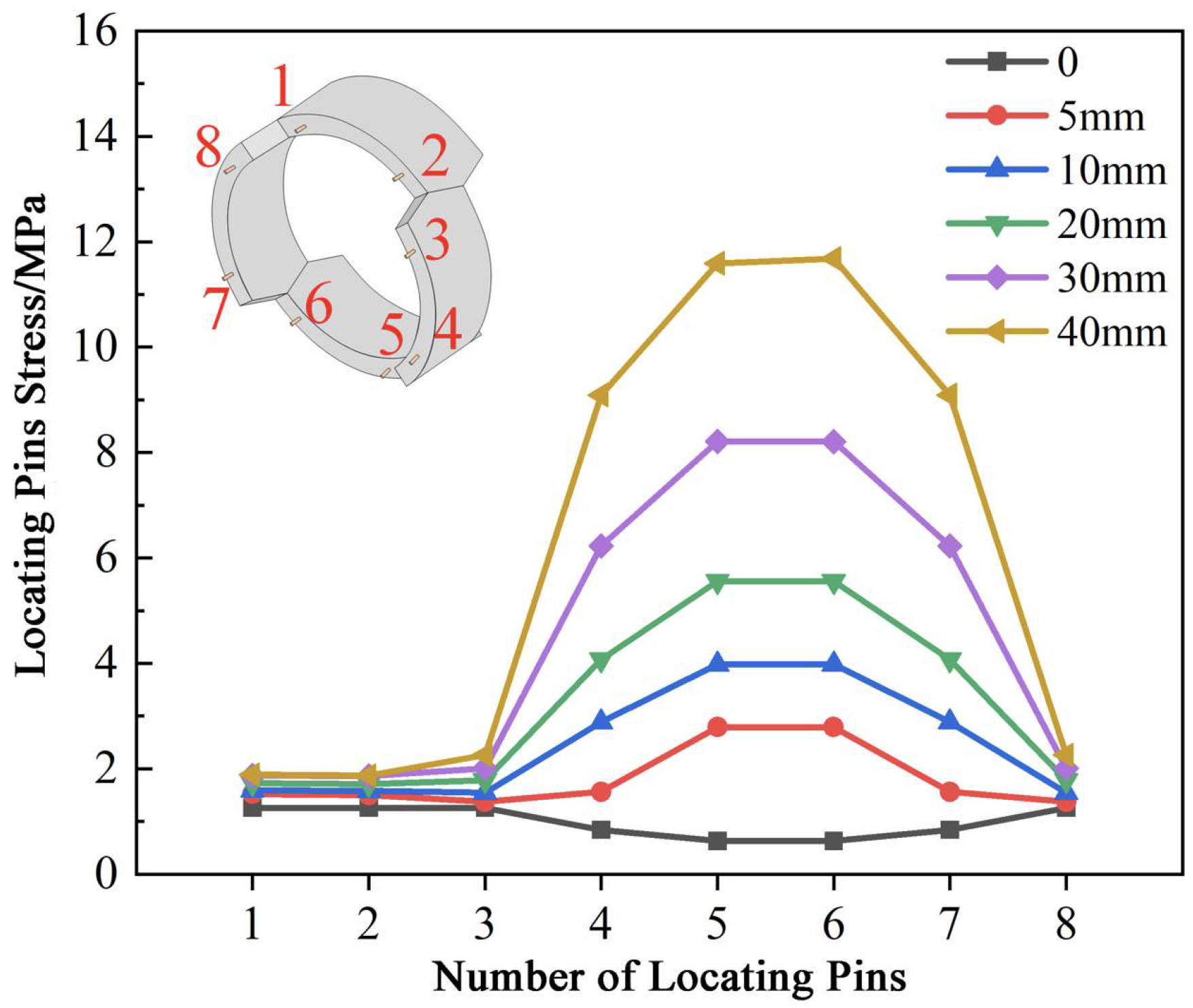
3.1.3. Stress of Locating Pins

This section examines the eight locating pins positioned on the middle ring segment lining under V-class surrounding rock. Figure 8 displays the tensile stress of each locating pin under different working conditions.
In the case of no misalignment defect, the vertical pressure of surrounding rock is transmitted from the crown segment through the side segments to the invert segment. This results in the greatest deformation to raise a maximum tensile stress in the crown segment; the value is 1.10 MPa. With the increase in the crown segment misalignment, the maximum stress continues to be concentrated at the crown position. The positioning pins, designed to minimize the gaps between the segment rings, enable the structure to handle increased loads. Consequently, with greater misalignment, the tensile stress of the crown’s locating pins becomes more pronounced. At positions 1 and 2, the maximum tensile stress of the pins can reach 11.20 MPa. However, this underscores the critical role of maintaining the structural integrity of the tunnel under varying working conditions.

3.2. Misaligned Invert Segment

3.2.1. Circumferential Stress of Segment

Figure 9 exhibits the maximum circumferential stress distributions and the peak values of the circumferential stresses on the inner and outer surfaces of the middle cross-section of the middle ring segment with V-class surrounding rock.
As the misalignment of the invert segment increases, the fluctuations in the tensile and compressive stresses at the crown and invert of the arch become more significant. The peak values of circumferential tensile stress are located at the middle of the arch invert of the misaligned ring, while the peak values of compressive stress are found at the middle of the crown segment. As shown in Figure 9b, with a 40 mm misalignment, the maximum tensile and compressive stresses in the segment ring reach 2.48 MPa and −2.78 MPa, respectively. The increments in maximum tensile stress under various conditions are 13%, 11%, 29%, 21% and 17%, while the increments in maximum compressive stress are 58%, 19%, 26%, 20% and 24%. Considering the tensile stress limit is 2.24 MPa for C50 concrete [18], the tensile stress of 2.48 MPa indicates the cracking of the concrete at the maximum crown segment misalignment. Meanwhile, the tensile stress of 2.05 MPa at a 30 mm segment misalignment reaches 91.5% of the limit stress, indicating a high potential for cracking.
Therefore, the segment lining presents greater resilience to compressive stresses, while the presence of an invert segment misalignment renders tensile stress a critical factor in evaluating the risk of structural failure.

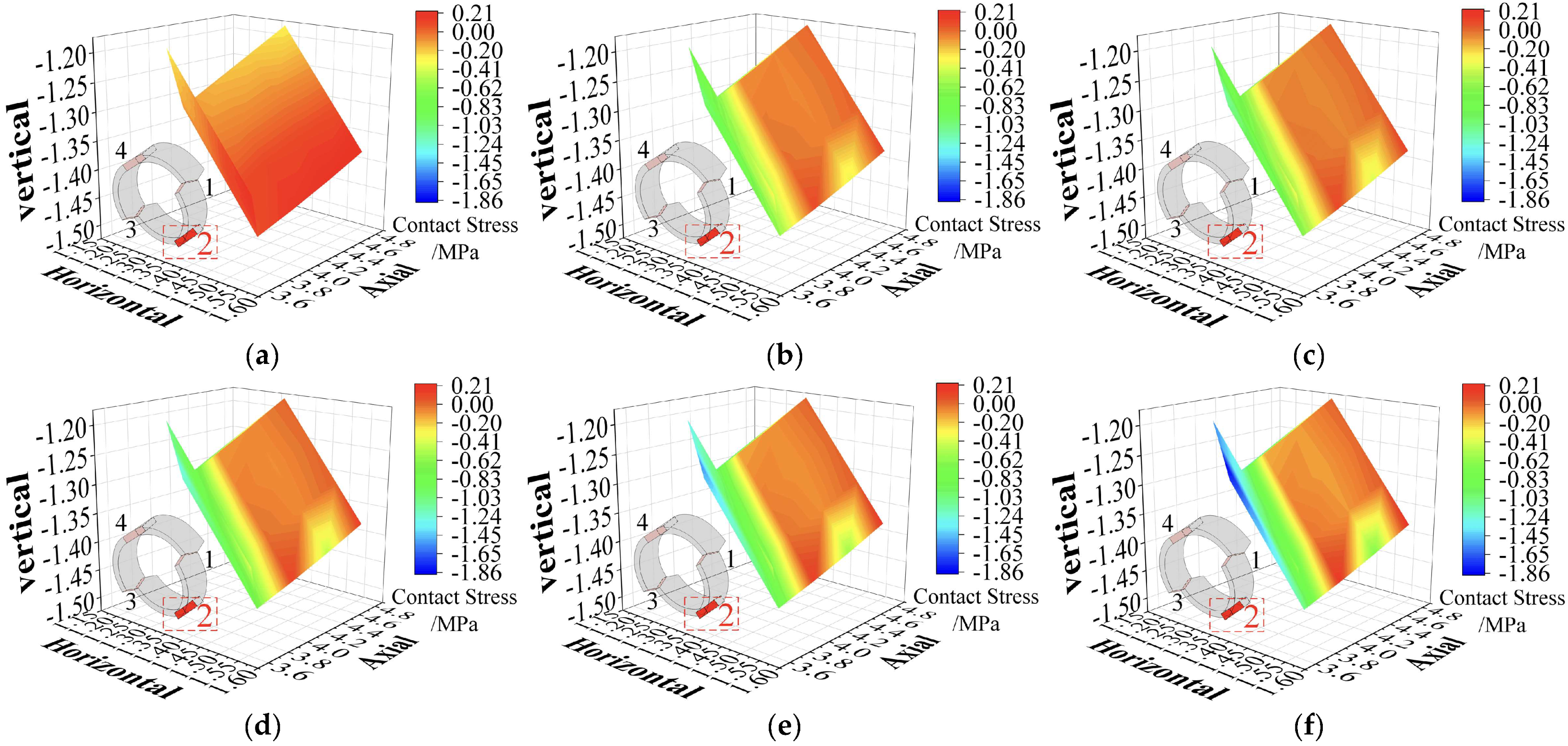
3.2.2. Segment Contact Stress

This section examines the variations in contact stress between segments at different misalignments of invert segments. Figure 10 and Figure 11 illustrate the contact surface stress distribution of contact surfaces 1 and 2 for each invert segment misalignment.
The invert segment misalignment defect in the segment lining results in an uneven force distribution at the misalignment site. This causes notable changes in the compressive stress on the contact surface between the misaligned invert segment and the adjacent side segments. As the defect increases, contact surface 1 predominantly experiences an increase in compressive stress; the contact stress between the adjacent rings on contact surface 2 shows minimal variation, while the contact stress between the misaligned invert segment and the side segments continuously escalates with the size of the defect. At the maximum defect level, the peak tensile stress on contact surface 1 is recorded at 0.12 MPa, and the peak compressive stress reaches −1.63 MPa. On contact surface 2, the peak tensile stress is 0.21 MPa, and the peak compressive stress is −1.86 MPa. Notably, in all cases, the stresses on the contact surfaces remain within the prescribed design standard values, and no failure phenomenon is observed, indicating that the structure maintains its integrity even under significant misalignment conditions.

3.2.3. Stress of Locating Pins

Figure 12 illustrates the tensile stress of each positioning pin under different conditions. It can be seen that the stress variations in the positioning pins near the invert segment intensify with the increasing misalignment of the invert segment. In the case of no defect, the positioning pins at the crown experience the maximum tensile stress. With the increase in defect degree, the structural stress gradually redistributes, with the highest stress shifting to the ring segment at the invert. The positioning pins are designed to prevent gaps between segment rings, thereby enabling them to handle increased loads. Consequently, as the defect enlarges, the tensile stress on the positioning pins at the arch invert becomes more pronounced. The maximum tensile stress on these positioning pins, particularly at positions 5 and 6, reaches a substantial 10.8 MPa.

4. Conclusions

This paper presents a numerical simulation study on the stress characteristics of segment linings at a burial depth of 87 m, focusing on both crown and invert segment misalignment. The study yields the following conclusions:
(1) Under the influence of crown or invert segment misalignment defects, the trend of tensile stress becomes more pronounced at the corresponding crown or invert segment, identified as the structure’s weak point in such cases. With a 40 mm misalignment, the maximum tensile stress of 2.60 MPa on a misaligned crown segment or 2.48 MPa on a misaligned invert segment is over the tensile stress limit for C50 concrete of 2.24 MPa, indicating a substantial risk of cracking. At a 30 mm misalignment, the tensile stress of 2.03 MPa on the misaligned crown segment or 2.05 MPa on the misaligned invert segment, respectively, reaches 90.6% and 91.5% of the limit stress, indicating a high potential for cracking.
(2) With a single-directional misalignment of segment linings, an increased tensile stress is created on the misaligned segment at the crown or invert. With the weaker surrounding rock in V-class, when the misalignment is over 30 mm, the misaligned segment will face a risk of cracking. Therefore, it is crucial to control misalignment defects during the installation of segment lining. Due to the deformation of segment lining being directly related to the modulus of elasticity of the concrete, the segment with a lower strength of concrete will create a larger deformation, facing the issue of cracking. Therefore, a high-strength concrete should be applied to increase its cracking resistance when the misalignment is over 30 mm. In this aspect, the threshold of misalignment will change with the different strength of the concrete.
(3) The contact surfaces primarily endure compressive stress, especially at the points where the segments are misaligned; however, the stress does not pose an identifiable safety risk. The locating pins show an evident increase in tensile stress at misaligned positions, with a maximum tensile stress of 10.8–11.2 MPa, which is only 3.5%–3.6% of the 310 MPa tensile strength of steel. This indicates that the stress on each locating pin is lower than the tensile strength. Therefore, no countermeasure needs to be applied to strengthen the pins or mitigate the tensile stress.
(4) This study only researched the effect of single-directionally misaligned segments on the mechanical properties of segment lining. However, multidirectional misalignment also exists in practical engineering, which can produce an influence on the load-bearing performance of the tunnel. Future research should further explore the impact of multidirectional misalignment under different types of surrounding rock to fully assess its impact on structural safety.

Author Contributions

Methodology, F.L. and S.Z.; conceptualization, P.S. and H.W.; validation and data curation, Y.H., P.S. and Z.Z.; writing—original draft preparation, P.S. and Y.H.; writing—review and editing, Z.Z., H.W. and F.L.; supervision and funding acquisition, S.Z. All authors have read and agreed to the published version of the manuscript.

Funding

This work was supported by the Fund for First-Class Discipline Innovation Team of Henan, China (grant no. CXTDPY-6).

Data Availability Statement

The data used and/or analyzed in this study are available from the corresponding author upon reasonable request.

Conflicts of Interest

Authors Yitao He and Zhixiao Zhang were employed by the company Anyang Zhongzhou Water Supply Co., Ltd. The remaining authors declare that the research was conducted in the absence of any commercial or financial relationships that could be construed as a potential conflict of interest.

References

  1. Li, X.; Cao, G.; Yao, G.; Yan, Z.; Ding, X.; Zhao, S. Optimization of anchor groove and its forming techniques with permanent formwork for prestressed concrete lining of high-pressure water conveyance tunnel. J. North China Univ. Water Resour. Electr. Power 2022, 43, 13–18. [Google Scholar]
  2. Wang, X.; Behbahani, S.; Iseley, T.; Azimi, M.; Wei, X.; Wei, G.; Shi, Y. Vertical tunneling in China—A case study of a hydraulic tunnel in Beihai. Tunn. Undergr. Space Technol. 2021, 107, 103650. [Google Scholar] [CrossRef]
  3. Deng, M.; Tan, Z. Study on boring indexes and key issues of tunnel boring machine cluster construction of super-long tunnels. Tunn. Constr. 2021, 41, 1809–1826. [Google Scholar]
  4. Sun, W.; Shi, M.; Zhang, C.; Zhao, J.; Song, X. Dynamic load prediction of tunnel boring machine (TBM) based on heterogeneous in-situ data. Autom. Constr. 2018, 92, 23–34. [Google Scholar] [CrossRef]
  5. Huang, X.; Liu, W.; Zhang, Z.; Zhuang, Q.; Zhu, Y.; Wang, Q.; Kwok, C.Y.; Wang, S. Structural behavior of segmental tunnel linings for a large stormwater storage tunnel: Insight from full-scale loading tests. Tunn. Undergr. Space Technol. 2020, 99, 103376. [Google Scholar] [CrossRef]
  6. Zhang, Z.; Wang, B.; Wang, X.; He, Y.; Wang, H.; Zhao, S. Safety risk assessment of TBM tunnel construction based on fuzzy evidence reasoning. Processes 2022, 10, 2597. [Google Scholar] [CrossRef]
  7. Su, A.; Wang, S.; He, C.; Lu, D.; Fang, R. Disease characteristics and causes analysis of segments of shield tunnels in composite stratum during construction. Chin. J. Geotech. Eng. 2019, 67, 683–692. [Google Scholar]
  8. Li, X.; Lin, X.; Zhu, H.; Wang, X.; Liu, Z. Condition assessment of shield tunnel using a new indicator: The tunnel serviceability index. Tunn. Undergr. Space Technol. 2017, 67, 98–106. [Google Scholar] [CrossRef]
  9. Yao, Z.; Xiong, Y.; Fu, L.; Quan, Y.; Niu, W.; Hu, L. Failure mechanism and support technology of surrounding rocks in lithologic interface area of deep-buried tunnel bored by tunnel boring machine. Tunn. Constr. 2023, 43, 102–111. [Google Scholar]
  10. Panji, M.; Mojtabazadeh-Hasanlouei, S. On subsurface box-shaped lined tunnel under incident SH-wave propagation. Front. Struct. Civ. Eng. 2021, 15, 948–960. [Google Scholar] [CrossRef]
  11. Panji, M.; Mojtabazadeh-Hasanlouei, S. Seismic ground response by twin lined tunnels with different cross sections. SN Appl. Sci. 2021, 3, 787. [Google Scholar] [CrossRef]
  12. Su, K.; Zhou, X.; Wu, H.; Mao, W.; Geng, B. Structure characteristics of parallelogram segment lining in deep-buried tunnel under hydraulic pressure. Water Resour. Power 2019, 37, 45–48. [Google Scholar]
  13. Su, K.; Zhao, X.; Yang, F.; Geng, B.; Wang, M. Structure characteristics of a new kind of parallelogram segment lining in TBM tunnel. Eng. J. Wuhan Univ. 2020, 53, 471–482. [Google Scholar]
  14. Li, H.; Li, X.; Liu, H. Deformation and failure mechanism of metro shield tunnel subjected to buried fault dislocation. Eng. Fail. Anal. 2023, 15, 107551. [Google Scholar] [CrossRef]
  15. Li, H.; Li, X.; Liu, H. Analytical solution for evaluating the effects of buried fault dislocation on segmental tunnel considering the plastic yield behavior of circumferential joints. Alex. Eng. J. 2024, 97, 319–332. [Google Scholar] [CrossRef]
  16. Liu, X.; Bai, Y.; Yuan, Y.; Mang, H. Experimental investigation of the ultimate bearing capacity of continuously jointed segmental tunnel linings. Struct. Infrastruct. Eng. 2015, 12, 1364–1379. [Google Scholar] [CrossRef]
  17. Wang, X.; Chen, J.; Zhang, Y.; Xiao, M. Seismic responses and damage mechanisms of the structure in the portal section of a hydraulic tunnel in rock. Soil Dyn. Earthq. Eng. 2019, 123, 205–216. [Google Scholar] [CrossRef]
  18. SL 191-2008; Design Code for Hydraulic Concrete Structures. China Hydropower Press: Beijing, China, 2008.
  19. GB/T 51438-2021; Standard for Design of Shield Tunnel Engineering. China Standard Press: Beijing, China, 2021.
  20. Sharghi, M.; Chakeri, H.; Afshin, H.; Dias, D. Analysis of the possible cracking and damages of tunnel lining segments during installing stage. Soil Mech. Found. Eng. 2021, 58, 287–294. [Google Scholar] [CrossRef]
  21. Sharghi, M.; Afshin, H.; Dias, D.; Jeong, H. 3D numerical study of the joint dislocation and spacing impacts on the damage of tunnel segmental linings. Structures 2023, 56, 104878. [Google Scholar] [CrossRef]
  22. Cavalaro, S.; Blom, C.; Aguado, A.; Walraven, J. New design method for the production tolerances of concrete tunnel segments. J. Perform. Constr. Facil. 2012, 26, 824–834. [Google Scholar] [CrossRef]
  23. Wei, G.; Feng, F.; Cui, Y.; Wang, X.; Diao, H.; Wu, Y. Research on the influence of foundation pit excavation on the lateral force and deformation of side shield tunnels based on full-scale experiments. Tunn. Undergr. Space Technol. 2023, 140, 105236. [Google Scholar] [CrossRef]
  24. Li, W.; Xu, J.; Han, L. Analysis on reason of cracks and translocation in 6# tunnel of general trunk line leading Yellow river. Water Resour. Hydropower Eng. 2002, 33, 13–14. [Google Scholar]
  25. Qin, J.; Zhu, W.; Chen, J. Study of dislocation of duct pieces and crack problems caused by shield attitude control. Constr. Technol. 2004, 33, 25–27. [Google Scholar]
  26. Xu, X.; Li, Z.; Wang, K.; He, H. Structural scheme of metro station constructed by enlarging large diameter shield tunnel and stress and deformation of its key joints. China Railw. Sci. 2021, 42, 66–76. [Google Scholar]
  27. Jin, Y.; Ding, W.; Xiao, M.; Sun, W.; Wu, W.; Ye, M.; Tu, X. Experimental research on sealing behavior of segmental joints of Sutong GIL utility tunnel under ultra-high water pressure. Tunn. Constr. 2020, 40, 538–544. [Google Scholar]
  28. Nabipour, M.; Rezapour, S.; Mohajeri, S. A parametric study on friction-loss in water conveyance tunnels considering misalignment of precast concrete segments. Tunn. Undergr. Space Technol. 2020, 96, 103221. [Google Scholar] [CrossRef]
  29. Ding, E.; Wei, Y.; Wang, Y.; Kang, G. Analysis of causes of tunnel segment misplacement and prevention and control measures from the perspective of mechanics. In Proceedings of the National Civil Engineering Construction Technology Exchange Meeting, Beijing, China, 21 December 2020. [Google Scholar]
  30. Chen, W.; Li, S.; Zhang, Z. Segment cracking analysis of double shield TBM tunnel in construction stage. Tunn. Constr. 2020, 40, 50–57. [Google Scholar]
  31. Wang, G.; Wang, Y.; Mu, J.; Sun, F. Seismic performance analysis of shield tunnel considering segment misalignment. J. Railw. Eng. Soc. 2021, 38, 93–101. [Google Scholar]
  32. Sun, W.; Li, X.; Cheng, K.; Jia, W.; Liu, H. Analysis on the influence of large diameter intercity railway tunnel under passing the main canal of the middle route of South-to-North Water Diversion Project. J. North China Univ. Water Resour. Electr. Power 2020, 40, 46–52. [Google Scholar]
  33. Meda, A.; Rinaldi, Z.; Caratelli, A.; Cignitti, F. Experimental investigation on precast tunnel segments under TBM thrust action. Eng. Struct. 2016, 119, 174–185. [Google Scholar] [CrossRef]
  34. Ding, W.; Wu, Y.; Zhang, X.; Qiao, Y. Effect of dislocation on flexural behavior of longitudinal segmental joint for shield tunnel. China J. Highw. Transp. 2023, 36, 256–265. [Google Scholar]
  35. Wang, H.; Chen, Z.; Ma, S.; Li, X.; Liu, S.; Zhao, S. Seismic performance analysis of shallow-buried large-scale three-box-section segment-connected pipeline structure under multiple actions. Sci. Rep. 2023, 13, 2584. [Google Scholar] [CrossRef] [PubMed]
  36. Wang, X.; Li, Y.; Xu, H. ANSYS Structural Analysis Unit and Application, 1st ed.; China Communications Press: Beijing, China, 2011; pp. 375–406. [Google Scholar]
  37. Chen, Z.; Zhao, S. Structural Finite Element Analysis Principle and Engineering Examples; Machine Industry Press: Beijing, China, 2024. [Google Scholar]
  38. Chen, Z.; Li, X.; Yang, Y.; Zhao, S.; Fu, Z. Experimental and numerical investigation of the effect of temperature patterns on behaviour of large scale silo. Eng. Fail. Anal. 2018, 91, 543–553. [Google Scholar] [CrossRef]
  39. Cao, Y.; Wang, P.; Jin, X.; Wang, J.; Yang, Y. Tunnel structure analysis using the multi-scale modeling method. Tunn. Undergr. Space Technol. 2012, 28, 124–134. [Google Scholar] [CrossRef]
Figure 1. A ring of segment lining of the tunnel.
Buildings 14 02198 g001
Figure 2. View of the 3D FEM of the shield tunnel for numerical analysis. (a) Surrounding rock model. (b) Detail model.
Buildings 14 02198 g002
Figure 3. Misalignment types of the segment lining. (a) Misaligned crown segment. (b) Misaligned invert segment.
Buildings 14 02198 g003
Figure 4. Analytical location of the middle ring for 3D FEM segment lining. (a) Misalignment defect surfaces. (b) Locating pins of the middle segment ring.
Buildings 14 02198 g004
Figure 5. Circumferential stress distribution on the middle ring of the segment lining with the misaligned crown segment. (a) Circumferential stress of the outer and inner layers. (b) Peak stress.
Buildings 14 02198 g005
Figure 6. Contact stress on contact surface 1 of the segment ring with a misaligned crown segment: (a) 0, (b) 5 mm, (c) 10 mm, (d) 20 mm, (e) 30 mm and (f) 40 mm.
Buildings 14 02198 g006
Figure 7. Contact stress on contact surface 2 of the segment ring with a misaligned crown segment: (a) 0, (b) 5 mm, (c) 10 mm, (d) 20 mm, (e) 30 mm and (f) 40 mm.
Buildings 14 02198 g007
Figure 8. Stress of locating pins with a misaligned crown segment.
Buildings 14 02198 g008
Figure 9. Distribution of the circumferential stress of the segment lining with the misaligned invert segment. (a) Circumferential stress of the outer and inner layers. (b) Peak stress.
Buildings 14 02198 g009
Figure 10. Contact stress on contact surface 1 of the segment ring with a misaligned invert segment: (a) 0, (b) 5 mm, (c) 10 mm, (d) 20 mm, (e) 30 mm and (f) 40 mm.
Buildings 14 02198 g010
Figure 11. Contact stress on contact surface 2 of the segment ring with a misaligned invert segment: (a) 0, (b) 5 mm, (c) 10 mm, (d) 20 mm, (e) 30 mm and (f) 40 mm.
Buildings 14 02198 g011
Figure 12. Stress of locating pins with the misaligned invert segment.
Buildings 14 02198 g012
Table 1. Main physical and mechanical parameters of the segment lining materials.
Type of MaterialCompressive Strength (MPa)Tensile Strength (MPa)Deformation Modulus (GPa)Poisson’s RatioDensity (kg/m3)
C50 concrete32.42.6434.50.12450
Peastone grouting8.0-3.00.271700
Locating pin-3102100.37800
Table 2. Main physical and mechanical parameters of the surrounding rock.
Type of Surrounding RockDensity (kg/m3)Internal Friction Angle (°)Cohesion (MPa)Deformation Modulus (GPa)Poisson’s Ratio
V2000200.080.50.40
Table 3. Working conditions of the shield tunnel with segment misalignment defects.
Working ConditionDefect TypeSegment Misalignment Size (mm)
1No defect0
2Misaligned crown segment5
310
420
530
640
7Misaligned invert segment5
810
920
1030
1140
Disclaimer/Publisher’s Note: The statements, opinions and data contained in all publications are solely those of the individual author(s) and contributor(s) and not of MDPI and/or the editor(s). MDPI and/or the editor(s) disclaim responsibility for any injury to people or property resulting from any ideas, methods, instructions or products referred to in the content.

