Article

The Influences of Positive and Negative Resal Effects on the Shear Performance of Tapered Girders with Corrugated Steel Webs

1
School of Civil Engineering, Jiangsu Open University, Nanjing 210017, China
2
School of Civil Engineering, Wuhan University, Wuhan 430072, China
3
Jiangxi Provincial Transportation Design and Research Institute Co., Ltd., Nanchang 330022, China
4
School of Civil Engineering, Central South University, Changsha 410075, China
*
Author to whom correspondence should be addressed.
Buildings 2024, 14(7), 2217; https://doi.org/10.3390/buildings14072217
Submission received: 14 May 2024 / Revised: 20 June 2024 / Accepted: 15 July 2024 / Published: 18 July 2024
(This article belongs to the Section Building Structures)

Abstract

:
This study theoretically and numerically examines the differences in shear performance between tapered and prismatic girder configurations with corrugated steel webs (CSWs) and investigates the influence of the Resal effect on the shear performance of tapered girders with CSWs. The vertical components of the inclined bottom slab forces (which are zero in prismatic cases) may decrease or increase the effective shear force on the CSWs, reflecting the positive and negative influences of the Resal effect. Based on these influences, this study introduces the concepts of positive and negative Resal effects and proposes an improved shear method to predict the effective shear forces acting on tapered CSWs. The results of the theoretical and finite element (FE) analyses show that the traditional shear method, which assumes CSWs bear all the shear force, is not applicable to tapered girders. The improved shear method significantly reduced the error in predicting shear forces within the CSWs, decreasing the maximum error from 42.25% (traditional method) to 7.71% (improved method) in specific sections. Quantitative analyses of three different types of girders with CSWs indicate that the Resal effect is influenced by both the internal forces and the structural form of the box girder. In cases of a positive Resal effect, the inclined bottom slab shares a considerable portion of the shear force with CSWs, resulting in a surplus shear capacity in the CSWs; conversely, under a negative Resal effect, there is an increase in the effective shear force on the web, which could lead to an overestimation of the shear buckling strength of CSWs. These findings highlight the necessity of incorporating Resal effects for accurate shear force predictions in tapered girders. By accurately predicting shear forces, engineers can enhance the performance and reliability of these structures, avoiding both overestimation and underestimation of shear capacities.

1. Introduction

The prestressed concrete box girder with corrugated steel webs (CSWs) is a new type of steel–concrete composite bridge. The substitution of conventional concrete webs with CSWs not only make full use of the shear capacity of steel webs but also the flexural capacity of the concrete slabs, in addition to considerably reducing the weight of the superstructure. It has the advantages of being lightweight, with a high prestressing efficiency, good seismic performance, and can effectively prevent cracks in concrete webs [1,2,3]. Since the construction of the world’s first prestressed concrete girder bridge with CSWs in France in 1986, this unique structural form has been gradually applied and developed all over the world. According to Japan’s Corrugated-Steel-Webs Bridge Association, more than 200 girder bridges using CSWs are now being built or have been completed in Japan. Recently, composite girder bridges with CSWs are also showing a favorable development trend in China, and more than 100 bridges with CSWs have been built for nearly two decades. Considering the rational distribution of forces and economic benefits, tapered box girders with variable depth are used in long-span bridge engineering. Advancements in the design theory of CSWs and modern construction techniques have led to the construction of longer bridge spans, with the longest girder span featuring CSWs now exceeding 170 m. Nowadays, how to make breakthroughs on the ultimate span of the continuous girder bridges with CSWs has become a research hotspot.
Due to the accordion effect, it is generally accepted that the concrete slab bears the entire longitudinal moment in the section, while most of the vertical shear is carried by the CSWs [4,5,6]. Hence, the shear buckling of CSWs is one of the controlling factors in the structural design of the bridge with CSWs. Extensive research has been carried out on the shear buckling and shear performance of CSWs. Luo and Edlund [7] proposed an analytical model to predict the shear strength of trapezoidal CSWs, emphasizing the importance of shear buckling modes in design. Hassanein and Kharoob [8] further refined these models by incorporating factors such as material yield strength and overall buckling strength. Ashrafi et al. [9] examined the impact of wave characteristics on the behavior of wavy steel shear walls, finding that vertical alignment of waves with girders significantly enhances shear capacity and reduces out-of-plane deformations. Recently, Amani et al. [10] addressed the imperfection sensitivity of plastic shear buckling in CSWs, demonstrating the significant impact of initial geometric imperfections on the ultimate shear capacity. Building on more than 100 experiments, Sause and Braxtan [11] evaluated previous formulas proposed for estimating the shear strength of CSWs and developed a more precise formula that considers the interaction among shear failure modes. Furthermore, Nie et al. [12] proposed a new design formula that predicts the shear strength of such structures through nonlinear buckling analysis.
Considering the rationality and economy of their design, tapered girders with CSWs have been increasingly used in modern long-span bridge construction in recent years. Consequently, the shear performance of these tapered girders has garnered significant attention from scholars. Hassanein [13,14] first studied the shear buckling behavior of tapered girders with CSWs using nonlinear finite element (FE) analysis and proposed a shear buckling strength formula. Li et al. [15] investigated the distortional performance of tapered girders with CSWs and suggested a diaphragm spacing equation for this kind of bridge. Li et al. [16] developed a general formula for calculating the shear stress of a prismatic composite box girder with CSWs, taking into account the effects of bending moments, shear forces, and axial forces, and verified the accuracy of the formula based on the results of FE analysis; however, it is impractical for engineering designs due to its complex differential equation solutions and high computational costs. Zhou et al. [17] conducted experimental and numerical analyses on tapered girders with CSWs, emphasizing the significant impact of the Resal effect—which refers to the additional shear forces induced by bending moments and axial forces in tapered girders—on shear forces and the necessity of revised calculation methods; the study highlighted that the traditional hypothesis, which assumes CSWs bear the entire vertical shear force, is inadequate for tapered girders. Instead, the shear capacity contributions from inclined concrete slabs must be considered to accurately predict shear performance. Subsequently, Zhou et al. [18] proposed a unified calculation formula for predicting shear stresses in both prismatic and tapered girders with CSWs, which was validated through extensive testing.
In fact, the Resal effect has both favorable and unfavorable impacts on the shear capacity of tapered CSWs, depending on the structural form and the combination of internal forces. Since the existing research does not consider the different Resal effects on the calculation of shear force on tapered CSWs, based on this, this paper proposes an improved shear method that considers the positive and negative Resal effects. Additionally, the factors contributing to the positive and negative Resal effects as well as the mechanisms of the Resal effect on adjusting the portion of the shear forces between the inclined bottom slab and CSWs were also investigated. Finally, by analyzing and comparing the calculation results of the FE analysis and the improved shear method, an error analysis is carried out, and the correctness of the improved shear method is verified.

2. Shear Force Calculation of Girder Bridges with CSWs

2.1. Existing Shear Calculation Methods
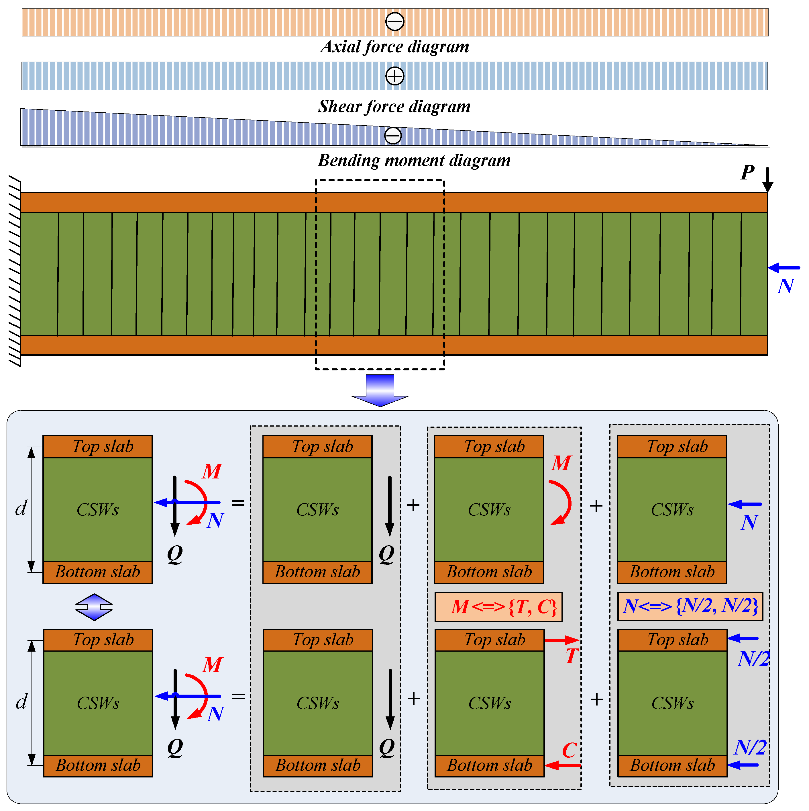
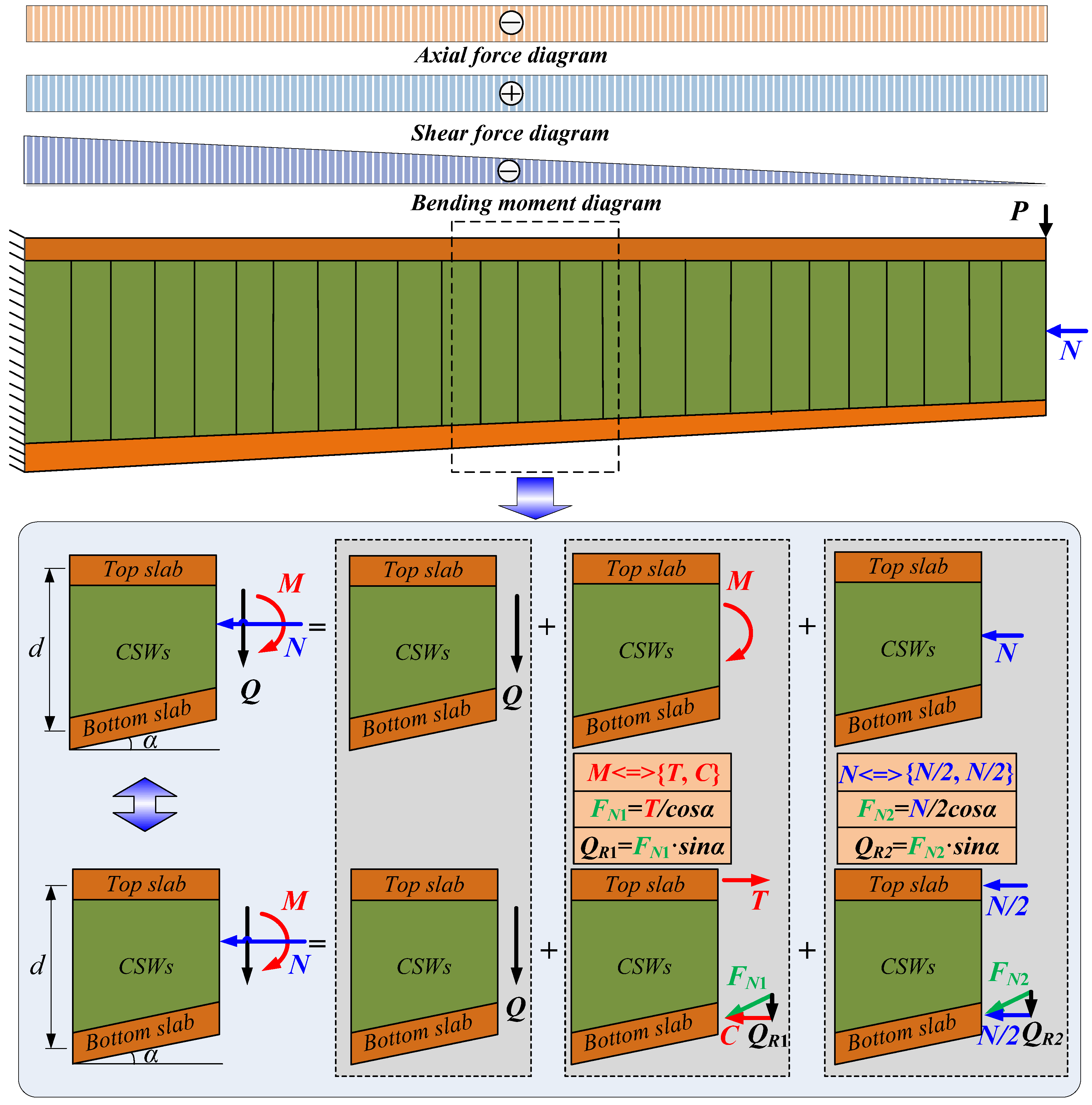
The current design codes in China and Japan [19,20] for girder bridges with CSWs assume the following: (1) due to the accordion effect [21,22], only the contributions of the concrete slabs to the sectional flexural and axial stiffness are considered; (2) ignoring the shear capacity of concrete slabs, it is assumed that CSWs bear all the shear on the section and the shear stress is evenly distributed along the web depth.
As shown in Figure 1, a prismatic cantilever girder is taken as an example to introduce the traditional shear method. Axial load (N) and vertical concentrated load (P) are applied at the free end of the cantilever girder, and a segment dx is selected as the research object, which is under the combined bending moment (M), axial force (N), and shear force (Q). As the CSWs have no resistance to the bending moment, the bending moment M can be equivalent to two equal and opposite axial forces acting on the neutral axis of the top and bottom slabs {T, C}. Similarly, the axial force is decomposed into two forces of N/2 acting on the center of the concrete slabs. Based on the above assumptions, the existing calculation method of shear force infers that the CSWs entirely bear all the shear force. Therefore, the actual shear force Qactual of CSWs can be expressed in Equation (1). This calculation method is named the traditional shear method.
Q a c t u a l = Q

2.2. Resal Effect

The axial force and bending moment induce an additional shear force at the bottom slab in tapered girders, which makes the inclined bottom slab significantly contribute to the shear capacity of the section, especially at the section where the internal forces are larger, the additional shear force is also larger. The existence of additional shear force will significantly influence the distribution of shear-sharing proportions between CSWs and bottom slabs.
As shown in Figure 2, a tapered cantilever girder with CSWs, under vertical and horizontal concentrated loads at the free end, was selected to illustrate the Resal effect. The shear force calculation, based on the Resal effect, is conducted through a comprehensive analysis of the tapered girder with CSWs, with the following basic assumptions: (a) the girder with CSWs demonstrates elastic behavior in accordance with Hooke’s Law; (b) the girder with CSWs is assumed to satisfy the quasi-plane section assumption under bending; (c) the CSWs are devoid of axial force, with the bending moment exclusively borne by the top and bottom concrete slabs. The inclination of the bottom slab in the horizontal direction is α. Selecting a micro-segment dx of the girder as the analysis object, it can be found that a combination of bending moment M, shear force Q, and axial force N is applied to the selected cross-section. Due to the accordion effect of CSWs, the bending moments are completely borne by the concrete slabs; therefore, the bending moment M can be equivalent to a pair of force couples {T, C} acting on the center of the top and bottom slabs (M = T·d = C·d), as shown in Figure 2. Apparently, the compression force of the bottom slab (FN1) and the equivalent force (C) satisfy C = FN1·cosα. Through the vector decomposition of the force acting on the inclined bottom slab, the vertical component QR1 of the compression force FN1 is an additional shear force induced by the bending moment in the inclined bottom slab. The axial force N is equivalent to a pair of forces {N/2, N/2} acting on the center of the top and bottom concrete slabs, respectively. Similarly, the compression force FN2 and the equivalent axial force N/2 satisfy the relationship of N/2 = FN2·cosα. The vertical component QR2 of FN2 is an additional shear force acting on the inclined bottom slab induced by the axial force N. Since the shear force on the section is self-balanced [22,23], additional forces −QR1 and −QR2 are generated on the CSWs, which are equal and opposite to the forces on the inclined bottom slabs. The additional shear forces QR1 and QR2 change the shear-sharing proportion between the CSWs and the inclined bottom slab, and the actual shear force on the CSWs is Qactual = QQR1QR2. The CSWs may no longer endure all the shear force in this section as the inclined bottom slab resists a considerable proportion of shear force, which is known as the Resal effect.

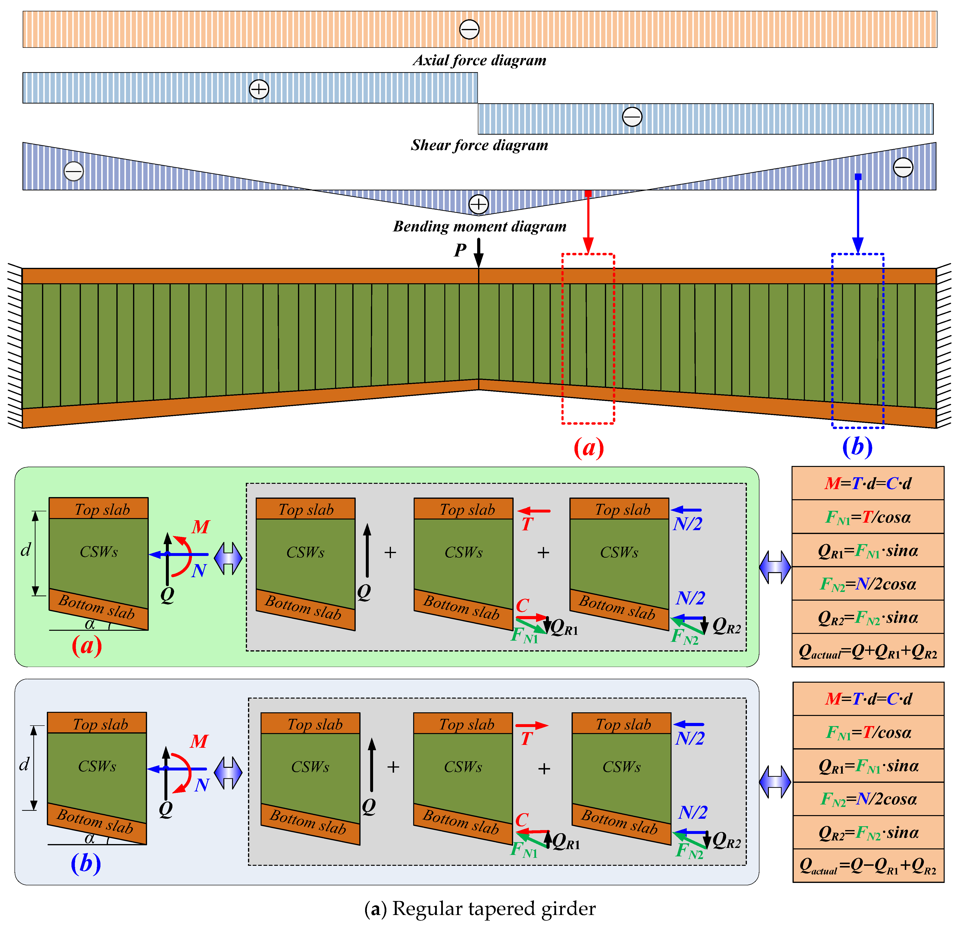
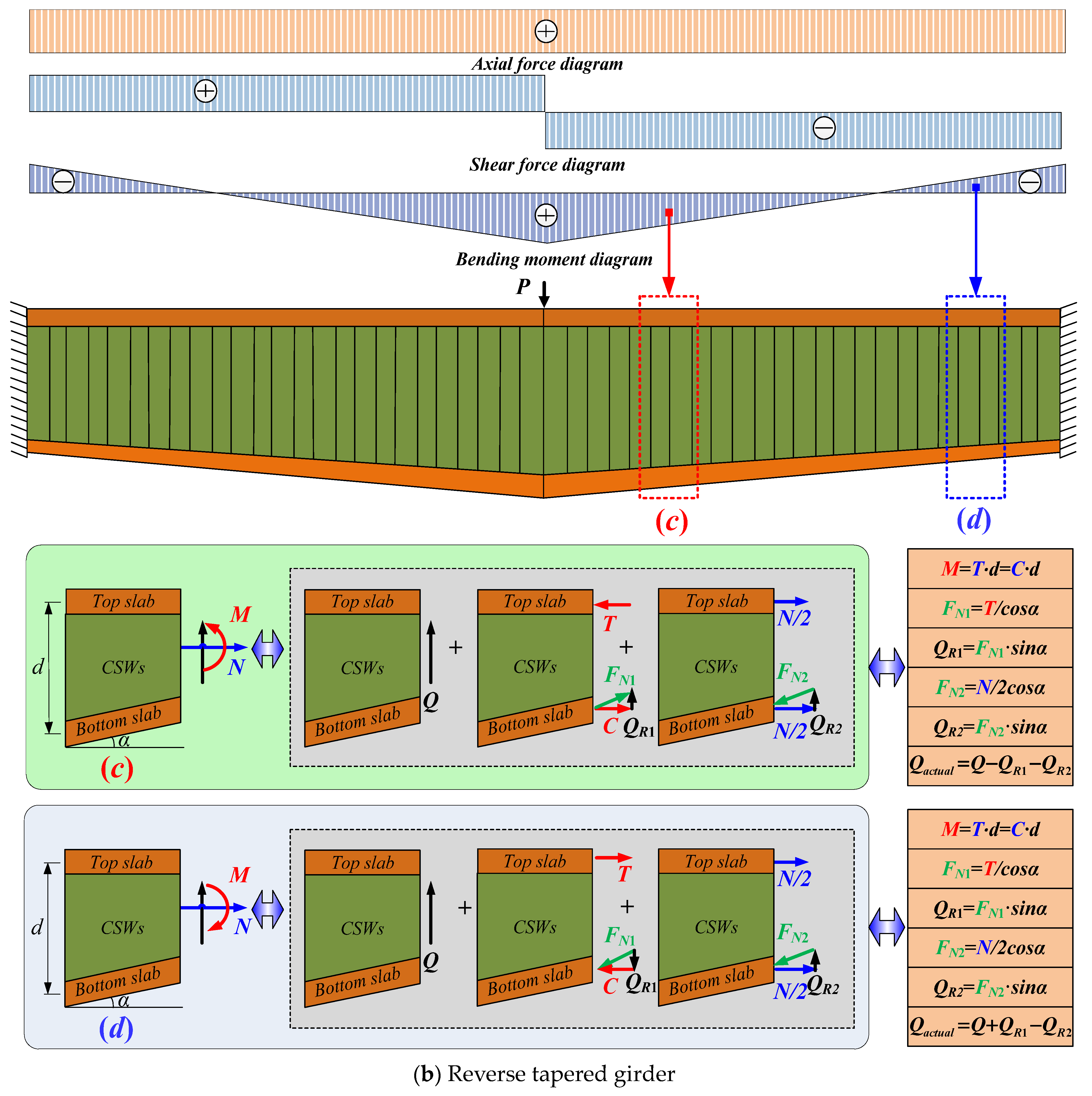
2.3. Improved Shear Method Considering Positive and Negative Resal Effects

Because the Resal effect activates the inclined bottom slab to resist shear force in tapered girders with CSWs, the conventional hypothesis that the shear force in the section is all borne by the web does not apply to tapered cases; therefore, the Resal effect must be considered when calculating the actual shear force on tapered CSWs. As seen in Figure 2, the direction of the additional shear force of the inclined bottom slab is related to the factors of inclination angle of the bottom slab (α) and internal forces (M and N). To explain the favorable and unfavorable influences of additional shear force on CSWs, the concept of positive and negative Resal effects is suggested; in addition, to compare the influence of different sectional profiles and internal force combinations on the Resal effect, two kinds of tapered girders are designed, namely, a regular tapered girder and reverse tapered girder as seen in Figure 3. The tapered girders with two fixed ends are subjected to a concentrated load in the mid-span. The micro-segments a and b in the regular tapered girder and micro-segments c and d in the reverse tapered girder were selected as the research objects. The selected micro-segments are simultaneously subjected to a combined action of axial force N, bending moment M, and shear force Q. Due to the different section forms and the internal force combinations, the direction of the shear force QR on the inclined bottom slab and the total shear force Q on the section may be the same or opposite. When QR is in the same direction as Q, the inclined bottom slab helps to share a certain part of the shear force for the CSWs. We call the situation that the inclined bottom slab contributes to resisting shear forces off the web as the positive Resal effect; conversely, if the additional shear force QR on the inclined bottom slab helps to increase the shear force on the CSWs, then it is called the negative Resal effect. Clearly, the positive Resal effect decreases the shear-sharing proportion of the CSWs, while the negative Resal effect increases it. The types of tapered girders, internal forces, the angle of the inclined bottom slab, and the effective web height of the considered section all determine the influence trends and degree of the Resal effects. The actual shear forces Qactual on the CSWs of micro-segments a, b, c, and d can be expressed in Equation (2):
Q a c t u a l = Q + Q R 1 + Q R 2 Q a c t u a l = Q Q R 1 + Q R 2 Q a c t u a l = Q Q R 1 Q R 2 Q a c t u a l = Q + Q R 1 Q R 2

3. Finite Element Model

Two types of tapered girders with different section forms (regular tapered girder (Model-1) and reverse tapered girder (Model-2) are established using ABAQUS to discuss the impact of different Resal effects on the shear force transfer efficiency of tapered CSWs, as shown in Figure 4a,b. Additionally, to study the distinction in resisting shear force between tapered and prismatic girders and to verify the positive and negative Resal effects in tapered girders, a prismatic girder (Model-3 in Figure 4c) is also established as a comparison. The FE model uses a box girder section with a length of 4000 mm and a concrete slab width of 759 mm. The top concrete slab has an 80-millimeter thickness. Model-1 has a linear height variation of 1000 mm at the fixed end to 800 mm at the mid-span and a linear thickness variation of 120 mm at the fixed end to 60 mm at the mid-span for the bottom concrete slab. Model-2 has a linear height variation of 800 mm at the fixed end to 1000 mm at the mid-span and a linear thickness variation of 60 mm at the fixed end to 120 mm at the mid-span for the concrete bottom slab. The height of Model-3 is 900 mm and the bottom concrete slab thickness is 80 mm. The CSWs have a 320 mm wavelength and a 5 mm thickness. They are made up of a flat panel with an 86-millimeter length and an inclined panel with a 74-millimeter projection length, a 44-degree folding angle, and a 44-millimeter corrugation height.
The C3D8R solid element is used to simulate concrete slabs, and the S4R shell element is used to simulate CSWs in the FE models, as illustrated in Figure 5. In the elastic phase, there is no shear slip between the CSWs and the concrete slabs at the connection interface. To ensure that the deflection of the common element nodes is coordinated under loading, the two materials are merged into a single instance using Boolean operations. Steel and concrete are assumed to be homogeneous and isotropic materials. Concrete has an elastic modulus of 3.46 × 10¹⁰ N/m2 and its Poisson’s ratio is 0.197. Steel has an elastic modulus of 2.06 × 10¹¹ N/m2 and its Poisson’s ratio is 0.3. A concentrated force of 168 kN is applied to the girder’s mid-span. By creating free body cuts, the shear forces on the top slab, CSWs, and bottom slab can be acquired separately. The influence of the positive and negative Resal effects on the shear performance of the tapered CSWs is investigated in the next section.
Since the model was subjected to static loading within the elastic phase throughout the FE analysis, the ABAQUS/Implicit solver was employed for the static analysis. A comprehensive mesh convergence study was conducted to determine the optimal mesh size, balancing accuracy, and computational efficiency. By incrementally refining the mesh and analyzing the resulting variations in key output parameters, it was identified that a mesh size of 20 mm achieves this balance effectively. This mesh size ensures that the model captures the essential stress and deformation characteristics without unnecessary computational overhead. The FE modeling method utilized in this study has been validated extensively in previous works [17,23], establishing the reliability and accuracy of the approach in predicting the shear response of tapered girders with CSWs.

4. Results and Analysis

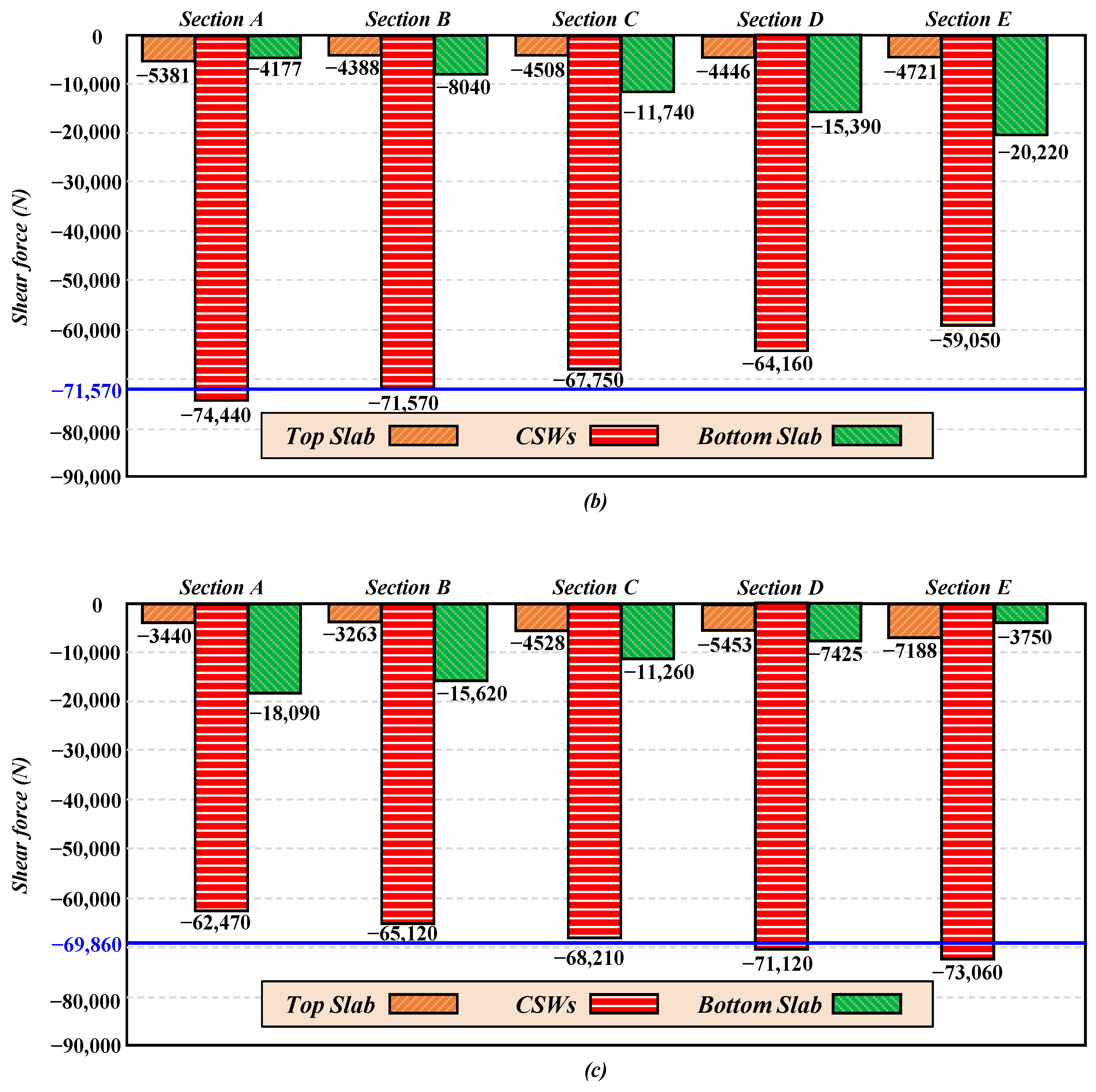
4.1. Shear Distribution between Concrete Slabs and CSWs

To quantify how the Resal effect influenced the shear distribution between concrete slabs and CSWs, a series of free body cuts in the longitudinal direction of the girders are defined in ABAQUS. The shear forces on the free body sections are extracted by integrating the shear forces at the element nodes, and the shear-sharing proportion between the CSWs and concrete slabs is investigated. Figure 6 shows the location of the selected free body sections of the three FE models and the internal forces of each section.
  • Prismatic girder
The shear distribution between the concrete slabs and CSWs in the prismatic girder is demonstrated in Figure 7a. Under a concentrated load of 168 kN, the theoretical shear force on the CSWs should be −84 kN but the actual shear force is slightly lower than the theoretical results because the concrete slabs also take a small proportion of the shear force. The shear force in each part of the section basically does not change in response to internal forces, and the Resal effect does not exist in the prismatic girder, which also shows that the traditional shear method in the current codes that assumes the CSWs bear all the shear force is valid for prismatic girders. The error of the traditional shear method can be controlled within 13%.
2.
Regular tapered girder
Figure 7b shows the shear force distribution between the concrete slabs and CSWs in the regular tapered girder, where the shear force carried by the top slab is negligible. Due to the Resal effect, the CSWs and inclined bottom slab bear the majority of the shear force in the section, and their shear forces vary greatly along the length of the girder with the change in the internal forces. By extracting the shear force of the CSWs at section B—where the bending moment is 0—as the reference value (−71,570 N), comparing it with other calculated sections, and combining it with the analytical model in Figure 3, the following is found: the additional shear force generated by the positive bending moment in the inclined bottom slab is in the opposite direction to the total shear force in the section A and B, which shows a negative Resal effect; consequently, the effective shear force of the CSWs is greater than the reference value. In the positive bending moment region from section C to section E, the additional shear force in the bottom slab is in the same direction as the total shear in the section, which shows a positive Resal effect, thus the effective shear force of the CSWs is less than the reference value. The Resal effect increases as the negative bending moment increases, and the actual shear force of CSWs reduces accordingly.
3.
Reverse tapered girder
Figure 7c shows the shear distribution between the concrete slabs and CSWs in the reverse tapered girder, extracting the shear force of the CSWs at the section where the bending moment is 0 (x = 1.28 m) as the reference value (−69,860 N). Since the axial force is a constant, the orientation and amplitude of the bending moment and shear force vary longitudinally. Among them, the shear force on the CSWs of sections A, B, and C is less than 69,860 N under combined positive moment and negative shear force, which shows a positive Resal effect. The shear force on the CSWs of sections D and E is greater than 69,860 N under the combined negative moment and negative shear force, showing a negative Resal effect. In comparison to Figure 7b, it can be inferred that the different tapered cross-sections may lead to different influences of the Resal effect.

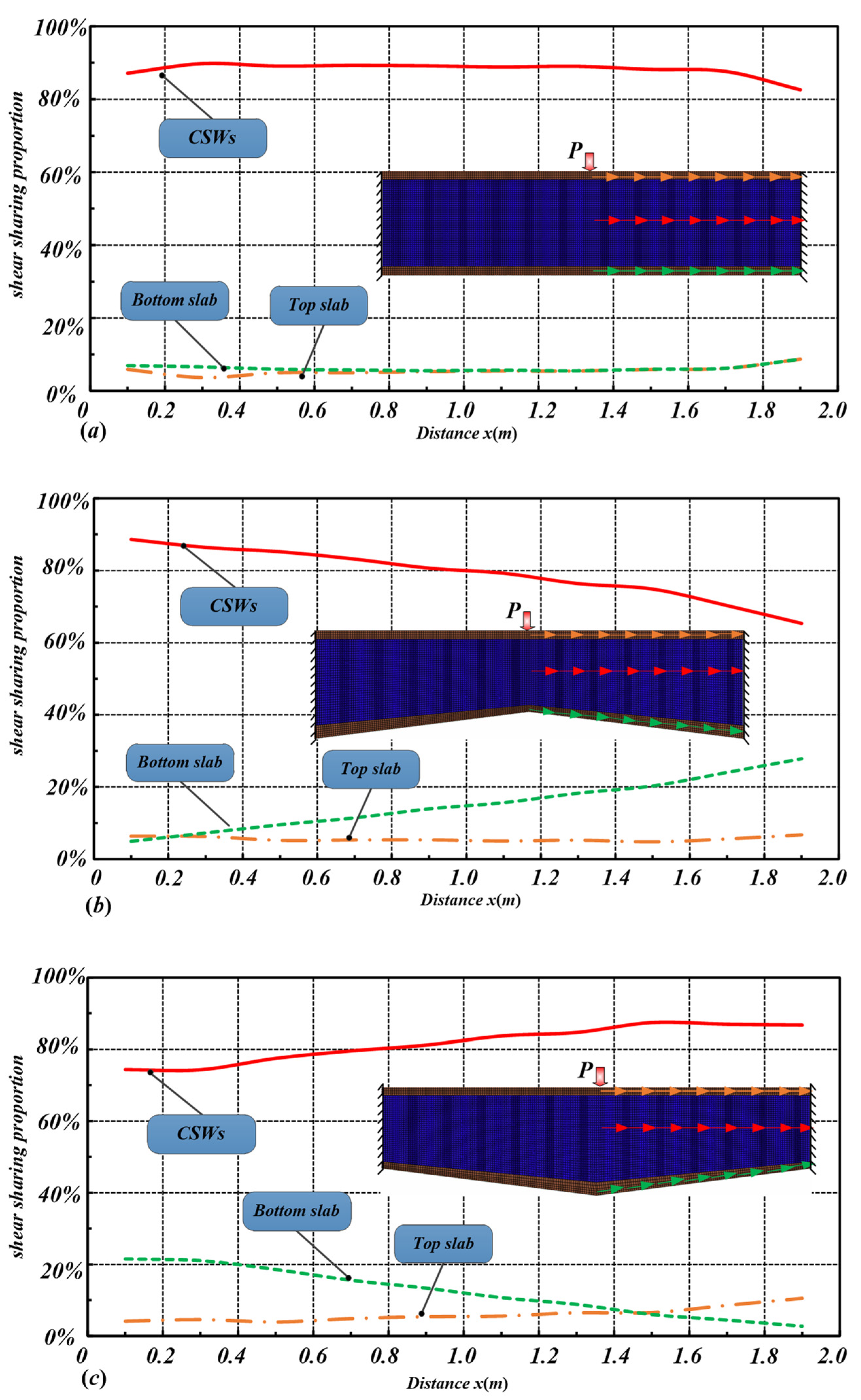
4.2. Shear-Sharing Proportions

Figure 8a–c show the distribution of shear-sharing proportions of the top slab, CSWs, and inclined bottom slab in the prismatic girder, regular tapered girder, and reverse tapered girder, respectively. It is found that the distribution of the shear-sharing proportions of the CSWs in tapered girders is different to that in a prismatic member because of the influence of the inducing additional shear force. The distribution of shear-sharing proportions between inclined bottom slabs and CSWs demonstrates a diametrically opposed trend in Figure 8b,c, which is due to the different Resal effects induced by the opposite variable section forms. The positive Resal effect will reduce the shear force of CSWs, while the negative Resal effect will increase it. Specifically, the shear-bearing ratio of CSWs in the regular tapered girder decreased from 88.62% to 65.37%, and the corresponding shear-sharing proportion of the inclined bottom slab increased from 4.97% to 27.86%; the shear-sharing proportion of CSWs in the reverse tapered girder increased from 74.37% to 86.74%, and the shear-sharing proportion of the inclined bottom slab decreased from 21.54% to 2.75%. It can be inferred that the traditional shear method is not reasonable in tapered girders, especially in the positive Resal effect region, the shear capacity of the CSWs has a certain surplus but the shear buckling strength of the CSWs is overestimated in the negative Resal effect region. In addition, the shear capacity of the inclined bottom slab also needs to be considered in predicting the shear strength of tapered girders with CSWs.

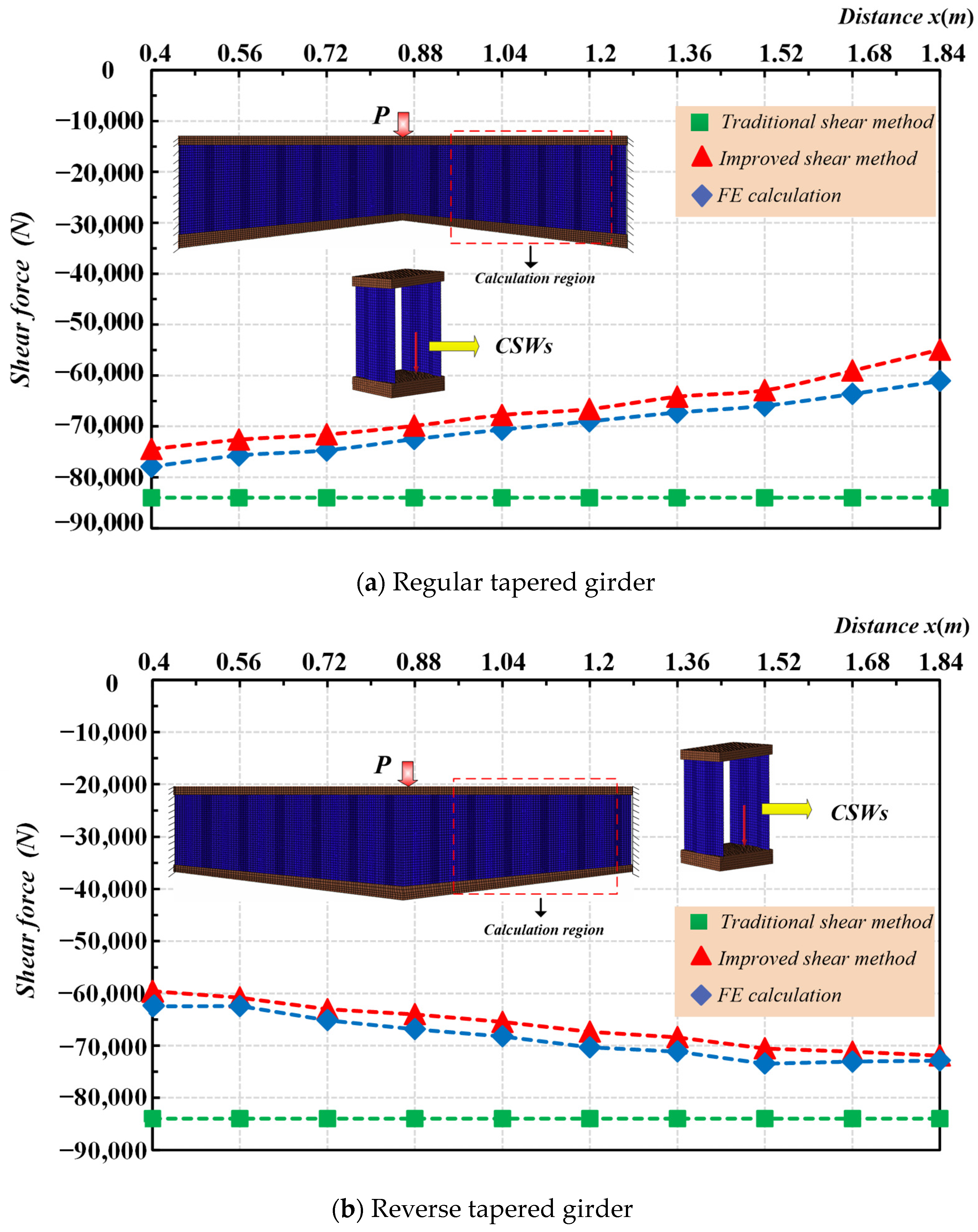
5. Verification of Improved Shear Method

To further confirm the accuracy of the improved shear method, Figure 9 compares the longitudinal distribution of actual shear forces on tapered CSWs obtained from the FE calculation, the traditional shear method, and the improved shear method. The distribution of shear forces predicted by the improved shear method agrees well with that of the FE calculation, while the calculation from the traditional shear method would produce unacceptable errors. The improved shear method considering the Resal effect can precisely calculate the effective shear force on the CSWs in the tapered girders. It may result in a large deviation between the traditional shear method and improved shear method, this is mainly because the Resal effect is not considered in the traditional shear method. In addition, because the positive or negative Resal effects in regular and reverse tapered girders are opposed to each other, the maximum error occurs in a regular tapered girder with CSWs near the middle span, while the maximum error in a reverse tapered case occurs in the right support.

6. Analysis of Calculation Errors

Due to the additional shear force induced by the Resal effect in tapered girders with CSWs, the inclined bottom slab contributes to the shear capability of the section under its influence; however, the additional shear force of the inclined bottom slab has not been included in the traditional shear method, so the traditional shear method cannot reflect the actual stress state of the tapered girders with CSWs. With the FE results as reference, Table 1 and Table 2 compare and analyze the calculation errors of the traditional shear method and the improved shear method in calculating the shear force of tapered CSWs.
The results in Table 1 and Table 2 show that the calculation errors of the shear force predicted from the traditional shear method increase as the bending moment increases, and the results predicted by the improved shear method are basically in agreement with the FE calculations. From the above analysis, it can be concluded that the error is mainly because the additional shear forces generated by the bending moments and axial forces are not under consideration in the traditional shear method. Therefore, the error is larger in those sections with larger shear forces and bending moments. Table 1 shows maximum error values up to 42.25% in section E using the traditional shear method, while the calculation error is only 7.71% when using the proposed improved shear method. In comparison to the traditional shear method, the latter has higher accuracy in calculating the shear force of CSWs in tapered girders.

7. Conclusion

In this study, the shear performance of tapered girders with CSWs is studied according to the theoretical analysis and FE simulation. The following are the main findings of this study:
(1) The traditional shear method for CSWs is suited for prismatic girders but inaccurate for tapered girders due to the Resal effect, which causes the vertical component of the axial force in the bottom slab to share part of the shear force, thereby influencing the effective shear force experienced by the CSWs. The occurrence of positive or negative Resal effects depends on both the internal forces and the structural configuration of the box girder;
(2) The concept of the positive and negative Resal effects in tapered girders with CSWs are theoretically proposed and numerically confirmed through FE simulation in this study. In cases of positive Resal effect, the inclined bottom slab will share a considerable portion of the shear force with the CSWs, so that the CSWs have a surplus of shear capacity. Under the negative Resal effect, there is an increase in the effective shear force of the web, posing a risk of overestimating the shear buckling strength of the CSWs;
(3) By incorporating both positive and negative Resal effects, this study has introduced an improved shear calculation method for determining the effective shear force on tapered CSWs. The error analysis revealed that the traditional shear method, which assumes CSWs bear all the shear force, is inadequate for tapered girders. The improved method reduced maximum prediction errors from 42.25% to 7.71%, demonstrating significant accuracy improvement.
While this study provides significant insights into the shear performance of tapered girders with CSWs and introduces the concepts of positive and negative Resal effects, there are several limitations to our current methodology. Firstly, the effect of prestressing, which is often applied in girder bridges with CSWs, was not considered in this study. Prestressing can have a significant influence on the shear behavior of box girders, necessitating further examination in future research. Secondly, this study focused on linear elasticity analysis, with upcoming research aiming to investigate nonlinear shear buckling responses. Future research will focus on investigating the influence of prestressing and the nonlinear behavior of box girders under both positive and negative Resal effects.

Author Contributions

Conceptualization, M.Z. and J.W.; Formal analysis, J.W.; Methodology, M.Z., Y.C. and J.W.; Resources, M.Z.; Software, Y.C.; Supervision, M.Z.; Validation, H.P.; Writing—original draft, F.X. and J.W.; Writing—review and editing, Y.C. and M.Z. All authors have read and agreed to the published version of the manuscript.

Funding

This research received no external funding.

Data Availability Statement

Data are contained within the article.

Conflicts of Interest

Author Huiteng Pei was employed by the company Jiangxi Provincial Transportation Design and Research Institute Co., Ltd. The remaining authors declare that the research was conducted in the absence of any commercial or financial relationships that could be construed as a potential conflict of interest.

References

  1. Deng, W.; Zhou, M.; Hassanein, M.F.; Zhang, J.; Liu, D.; An, L. Growth of Prestressed Concrete Bridges with Corrugated Steel Webs in China. Proc. Inst. Civ. Eng.-Civ. Eng. 2018, 171, 77–84. [Google Scholar] [CrossRef]
  2. Jung, K.; Kim, K.; Sim, C.; Kim, J.J. Verification of Incremental Launching Construction Safety for the Ilsun Bridge, the World’s Longest and Widest Prestressed Concrete Box Girder with Corrugated Steel Web Section. J. Bridge Eng. 2011, 16, 453–460. [Google Scholar] [CrossRef]
  3. Chen, X.C.; Pandey, M.; Bai, Z.Z.; Au, F.T.K. Long-Term Behavior of Prestressed Concrete Bridges with Corrugated Steel Webs. J. Bridge Eng. 2017, 22, 04017040. [Google Scholar] [CrossRef]
  4. Moon, J.; Yi, J.-W.; Choi, B.H.; Lee, H.-E. Lateral–Torsional Buckling of I-Girder with Corrugated Webs under Uniform Bending. Thin-Walled Struct. 2009, 47, 21–30. [Google Scholar] [CrossRef]
  5. Khalid, Y.A.; Chan, C.L.; Sahari, B.B.; Hamouda, A.M.S. Bending Behaviour of Corrugated Web Beams. J. Mater. Process. Technol. 2004, 150, 242–254. [Google Scholar] [CrossRef]
  6. Rosignoli, M. Prestressed Concrete Box Girder Bridges with Folded Steel Plate Webs. Proc. Inst. Civ. Eng.-Struct. Build. 1999, 134, 77–85. [Google Scholar] [CrossRef]
  7. Luo, R.; Edlund, B. Shear Capacity of Plate Girders with Trapezoidally Corrugated Webs. Thin-Walled Struct. 1996, 26, 19–44. [Google Scholar] [CrossRef]
  8. Hassanein, M.F.; Kharoob, O.F. Behavior of Bridge Girders with Corrugated Webs: (II) Shear Strength and Design. Eng. Struct. 2013, 57, 544–553. [Google Scholar] [CrossRef]
  9. Ashrafi, H.R.; Beiranvand, P.; Pouraminian, M.; Moayeri, M.S. Examining the Impact of Sheet Placement and Changes in Waves Characteristics on Behavior of Wavy Steel Shear Wall. Case Stud. Constr. Mater. 2018, 9, e00180. [Google Scholar] [CrossRef]
  10. Amani, M.; Al-Emrani, M.; Khalili, S. Imperfection Sensitivity of Plastic Shear Buckling Behavior in Corrugated Web Stainless Steel Beams. ce/papers 2023, 6, 1793–1798. [Google Scholar] [CrossRef]
  11. Sause, R.; Braxtan, T.N. Shear Strength of Trapezoidal Corrugated Steel Webs. J. Constr. Steel Res. 2011, 67, 223–236. [Google Scholar] [CrossRef]
  12. Nie, J.-G.; Zhu, L.; Tao, M.-X.; Tang, L. Shear Strength of Trapezoidal Corrugated Steel Webs. J. Constr. Steel Res. 2013, 85, 105–115. [Google Scholar] [CrossRef]
  13. Zevallos, E.; Hassanein, M.F.; Real, E.; Mirambell, E. Shear Evaluation of Tapered Bridge Girder Panels with Steel Corrugated Webs near the Supports of Continuous Bridges. Eng. Struct. 2016, 113, 149–159. [Google Scholar] [CrossRef]
  14. Hassanein, M.F.; Kharoob, O.F. Shear Buckling Behavior of Tapered Bridge Girders with Steel Corrugated Webs. Eng. Struct. 2014, 74, 157–169. [Google Scholar] [CrossRef]
  15. Li, L.; Zhou, C.; Wang, L. Distortion Analysis of Non-Prismatic Composite Box Girders with Corrugated Steel Webs. J. Constr. Steel Res. 2018, 147, 74–86. [Google Scholar] [CrossRef]
  16. Lifeng, L.; Jindong, C.; Wei, F.; Zhou, C. Research on shear stress calculation in variable cross-section of composite box girder with corrugated steel webs. J. Railw. Sci. Eng. 2019, 16, 3024–3032. [Google Scholar] [CrossRef]
  17. Zhou, M.; Liao, J.; An, L. Shear Properties of Tapered Box Girders with Steel Trapezoidally Corrugated Webs Considering Resal Effect. J. Bridge Eng. 2020, 25, 04019126. [Google Scholar] [CrossRef]
  18. Zhou, M.; Liao, J.; Zhong, J.; An, L.; Wang, H. Unified Calculation Formula for Predicting the Shear Stresses in Prismatic and Non-Prismatic Beams with Corrugated Steel Webs. Structures 2021, 29, 507–518. [Google Scholar] [CrossRef]
  19. Shandong Administration Market Regulation Code for Long Span Prestressed Concrete Composite Girder Bridge with Corrugated Steel Webs 2019. Available online: https://www.google.com.hk/url?sa=t&source=web&rct=j&opi=89978449&url=https://dbba.sacinfo.org.cn/attachment/downloadStdFile%3Fpk%3D28961f69dd68abf6be9e6f0b881b2ebeabdf82a67ac18a3fc73622f7bb7dfd1e&ved=2ahUKEwiqrJKEibKHAxU0aPUHHXyyHKgQFnoECBEQAQ&usg=AOvVaw2nn4_MLCigaEcDcWo8Ic5k (accessed on 12 June 2024).
  20. Ren, D.L.; Wan, S. Design and Application of PC Composite Box-Girder Bridge with Corrugated Steel Webs. Appl. Mech. Mater. 2011, 71–78, 1168–1172. [Google Scholar] [CrossRef]
  21. Sayed-Ahmed, E.Y. Behaviour of Steel and (or) Composite Girders with Corrugated Steel Webs. Can. J. Civ. Eng. 2001, 28, 656–672. [Google Scholar] [CrossRef]
  22. Jiang, R.J.; Kwong Au, F.T.; Xiao, Y.F. Prestressed Concrete Girder Bridges with Corrugated Steel Webs: Review. J. Struct. Eng. 2015, 141, 04014108. [Google Scholar] [CrossRef]
  23. Zhou, M.; Shang, X.; Hassanein, M.F.; Zhou, L. The Differences in the Mechanical Performance of Prismatic and Non-Prismatic Beams with Corrugated Steel Webs: A Comparative Research. Thin-Walled Struct. 2019, 141, 402–410. [Google Scholar] [CrossRef]
Figure 1. Analysis model of the traditional shear method.
Buildings 14 02217 g001
Figure 2. Analysis model of the Resal effect in tapered girder with CSWs.
Buildings 14 02217 g002
Figure 3. Calculation models of the improved shear method.
Buildings 14 02217 g003aBuildings 14 02217 g003b
Figure 4. Dimensions of FE models (in millimeters): (a) regular tapered girder; (b) reverse tapered girder; (c) prismatic girder.
Buildings 14 02217 g004aBuildings 14 02217 g004b
Figure 5. FE model of reverse tapered girder.
Buildings 14 02217 g005
Figure 6. (ac) The internal forces on each calculation section of each FE model.
Buildings 14 02217 g006aBuildings 14 02217 g006b
Figure 7. Shear forces carried by the top slab, CSWs, and bottom slab for (a) prismatic girder; (b) regular tapered girder; and (c) reverse tapered girder.
Buildings 14 02217 g007aBuildings 14 02217 g007b
Figure 8. Distribution of shear-sharing proportions of top slab, CSWs, and inclined bottom slab: (a) prismatic girder; (b) regular tapered girder; (c) reverse tapered girder.
Buildings 14 02217 g008
Figure 9. Comparison of shear force on the CSWs obtained by traditional shear method, improved shear method, and FE calculation.
Buildings 14 02217 g009
Table 1. Shear force on the CSWs for sections A–E obtained by the FE Model-1, traditional shear method Equation (1), and improved shear method Equation (2). (Unit: N·m; N.)
SectionMNFE Result
Equation (1) ②Equation (2) ③|①–③|/①|①–②|/①
A24,300−50,200−74,440−84,000−77,9094.66%12.84%
B0−50,200−71,570−84,000−74,7074.38%17.37%
C−25,140−50,200−67,750−84,000−70,6314.25%23.99%
D−49,030−50,200−64,160−84,000−67,2604.83%30.92%
E−74,480−50,200−59,050−84,000−63,6027.71%42.25%
Table 2. Shear force on the CSWs for sections A–E obtained by the FE Model-2, traditional shear method Equation (1), and improved shear method Equation (2). (Unit: N·m; N.)
SectionMNFE Result
Equation (1) ②Equation (2) ③|①–③|/①|①–②|/①
A68,40047,600−62,470−84,000−59,5564.66%34.46%
B44,00047,600−65,120−84,000−63,0243.22%28.99%
C18,80047,600−68,210−84,000−65,4634.03%23.15%
D−517047,600−71,120−84,000−68,3913.84%18.11%
E−30,70047,600−73,060−84,000−71,1602.60%14.97%
Disclaimer/Publisher’s Note: The statements, opinions and data contained in all publications are solely those of the individual author(s) and contributor(s) and not of MDPI and/or the editor(s). MDPI and/or the editor(s) disclaim responsibility for any injury to people or property resulting from any ideas, methods, instructions or products referred to in the content.

