
Study on the Bearing Capacity of the Polyethylene Pipe–Cured-In-Place Pipe Liner Composite Structure under External Pressure

Abstract
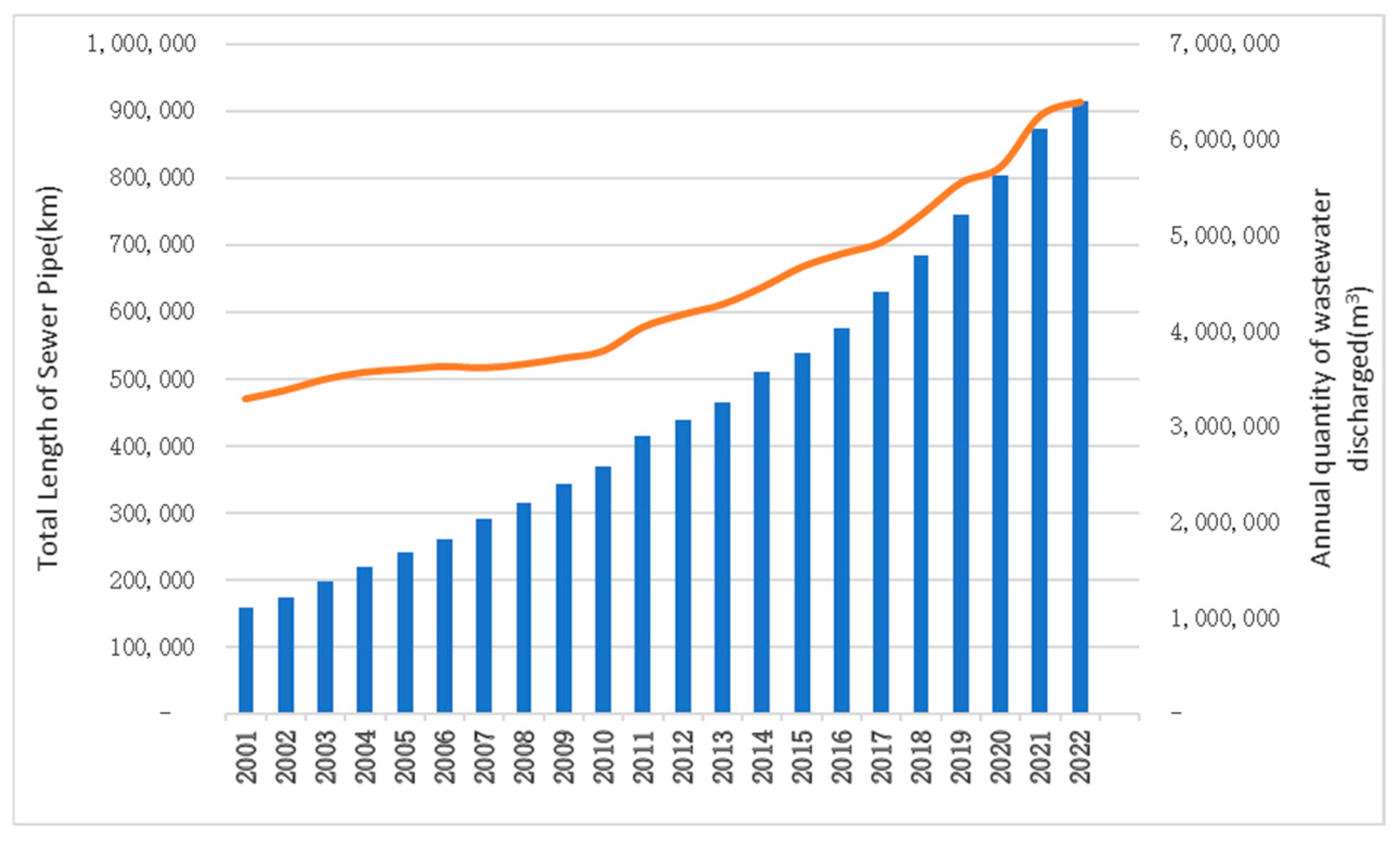
:1. Introduction
2. Test Design
2.1. Test Setup
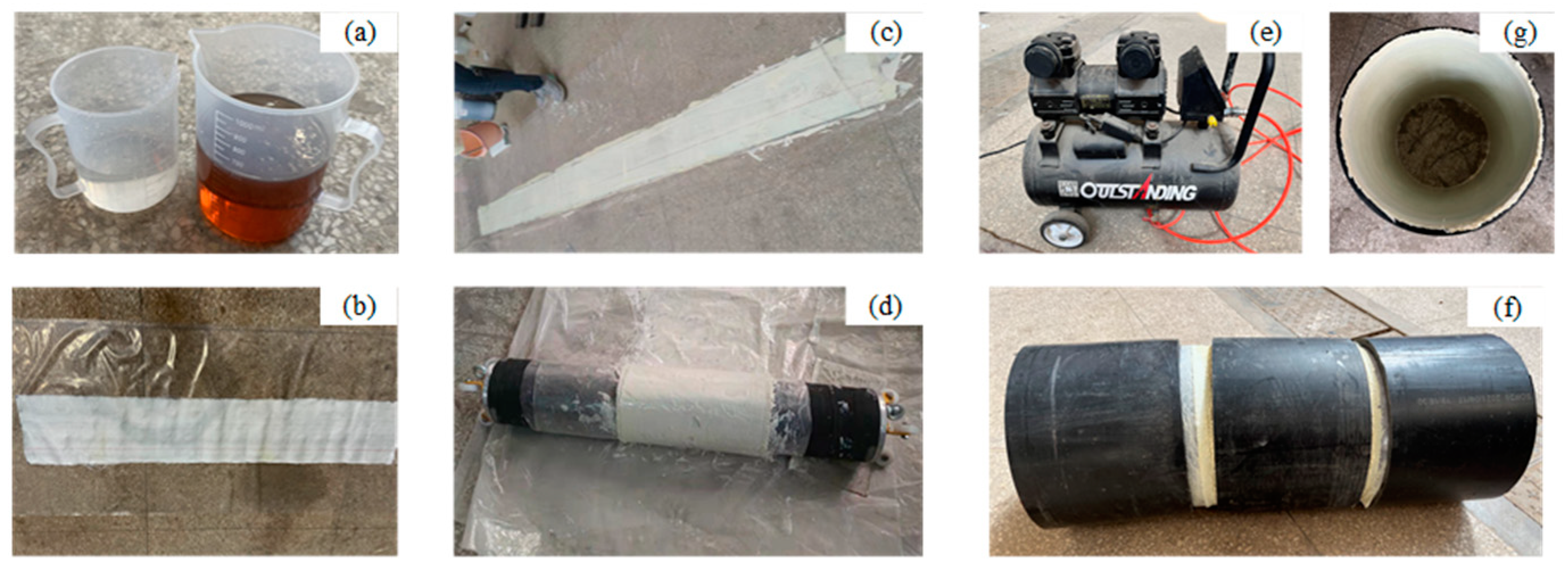
2.2. Sample Preparation
- (a)
- Mix resin and curing agent in a 2:1 ratio, then uniformly apply the mixture to fiberglass fabric with a density of 1050 g/m2;
- (b)
- Secure the impregnated hose onto an inflatable bladder, then move the bladder and hose into the pipeline to be repaired;
- (c)
- Inflate the bladder to ensure it adheres closely to the inner wall of the pipeline;
- (d)
- Allow it to cure at room temperature for 2 h, then release the gas and remove the bladder, trim the ends, and complete the sample preparation.
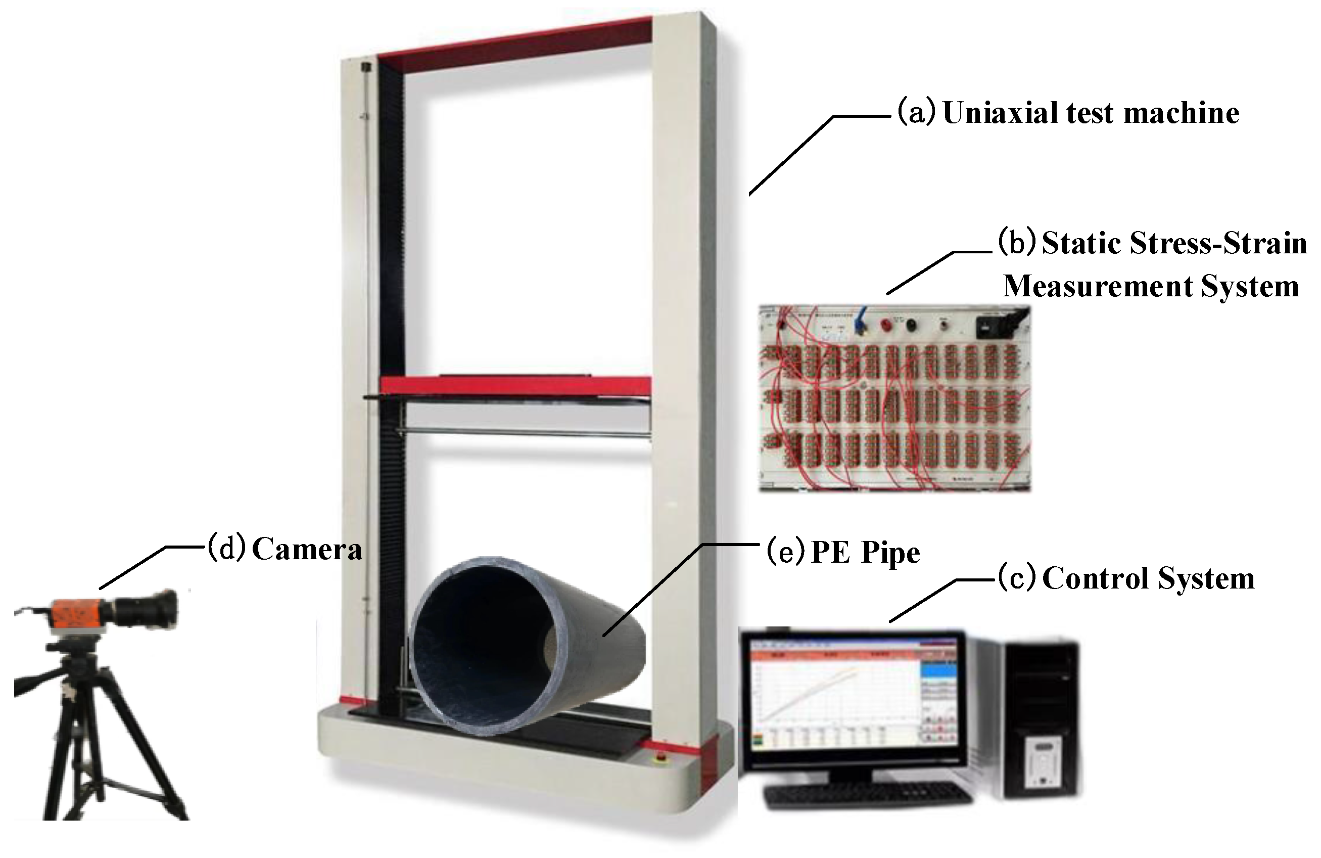
2.3. Instruments
2.4. Test Procedure
- (a)
- Place the prepared sample on the lower plate of the ring stiffness testing machine, ensuring that the sample is in close contact with the lower plate;
- (b)
- Verify that the strain measurement system and the photographic system are functioning correctly;
- (c)
- Activate the control system, set the loading rate to 10 mm/min, and establish the loading termination condition based on a predetermined deformation in the diameter direction of the sample;
- (d)
- Commence loading while simultaneously recording data on load, displacement, and strain, and capture images of the deformation process with an industrial camera;
- (e)
- Upon reaching the predetermined conditions or upon sample failure, stop the experiment and save the data.
3. Results and Discussion
3.1. The Effect of CIPP Liner on the Enhancement of the Ring Stiffness of PE Pipe
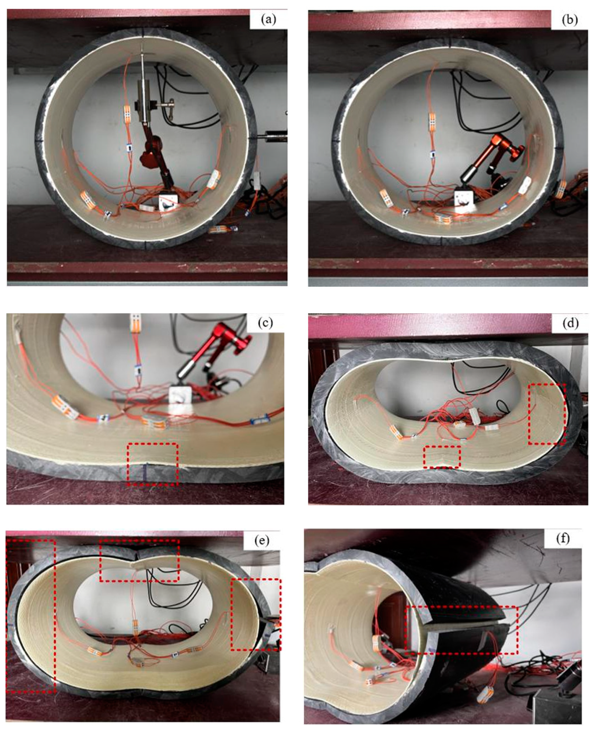
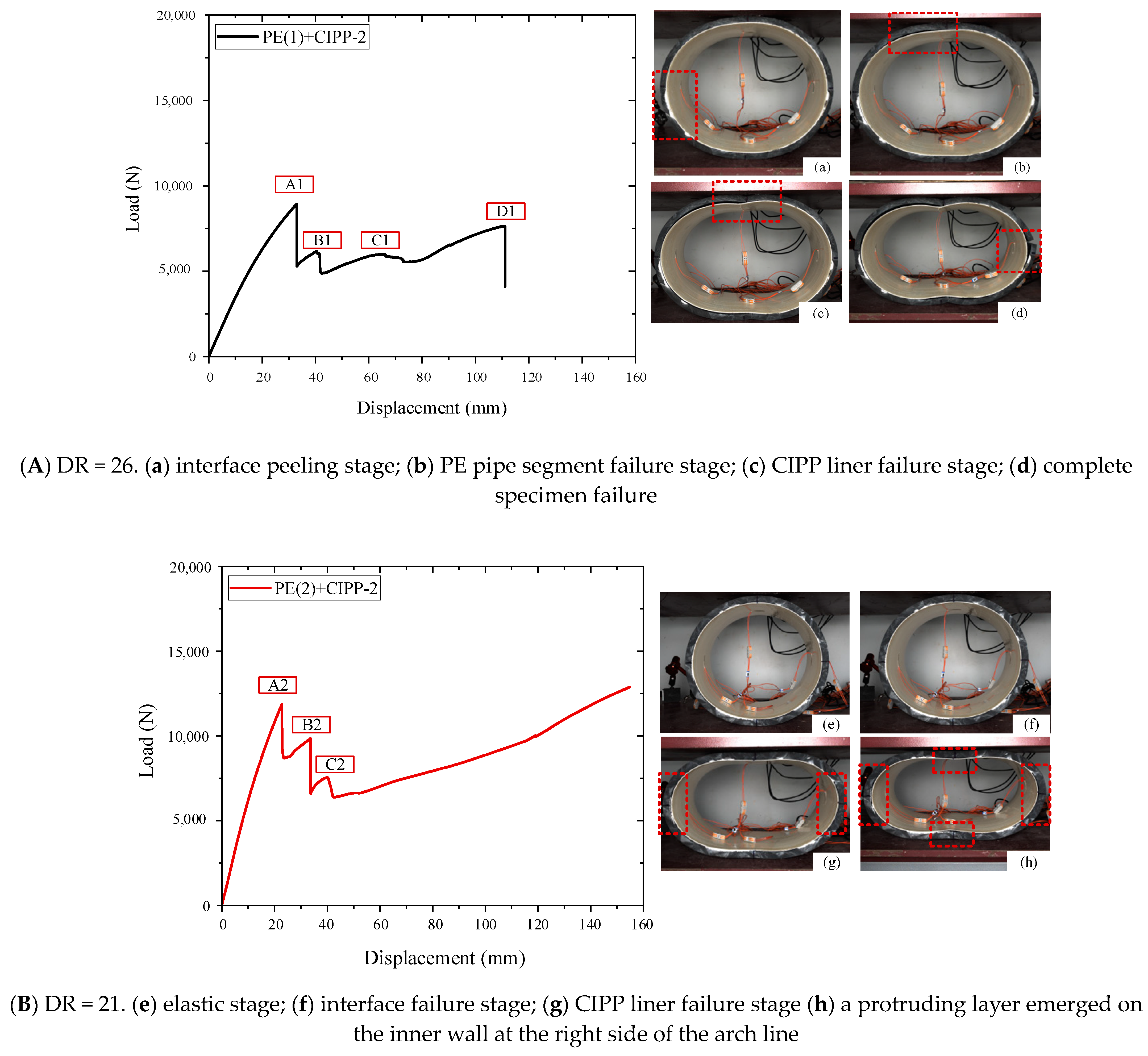
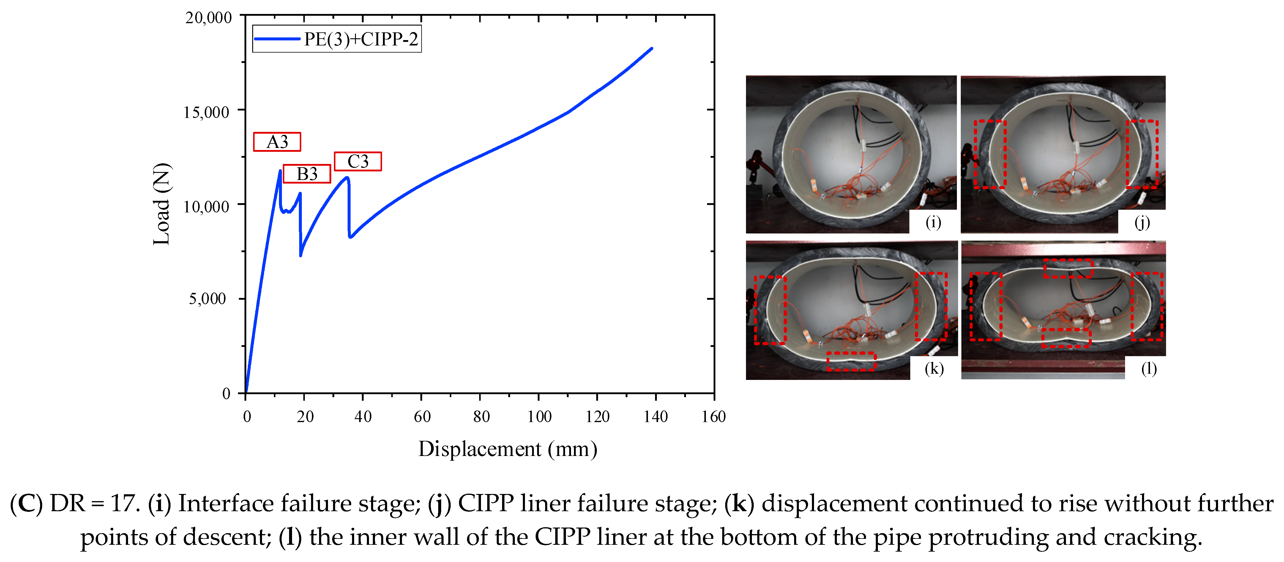
3.2. PE Pipe and PE Pipe–CIPP Liner Failure Mode
3.3. The Effect of Original PE Pipe’s DR on the Bearing Capacity of PE Pipe–CIPP Liner
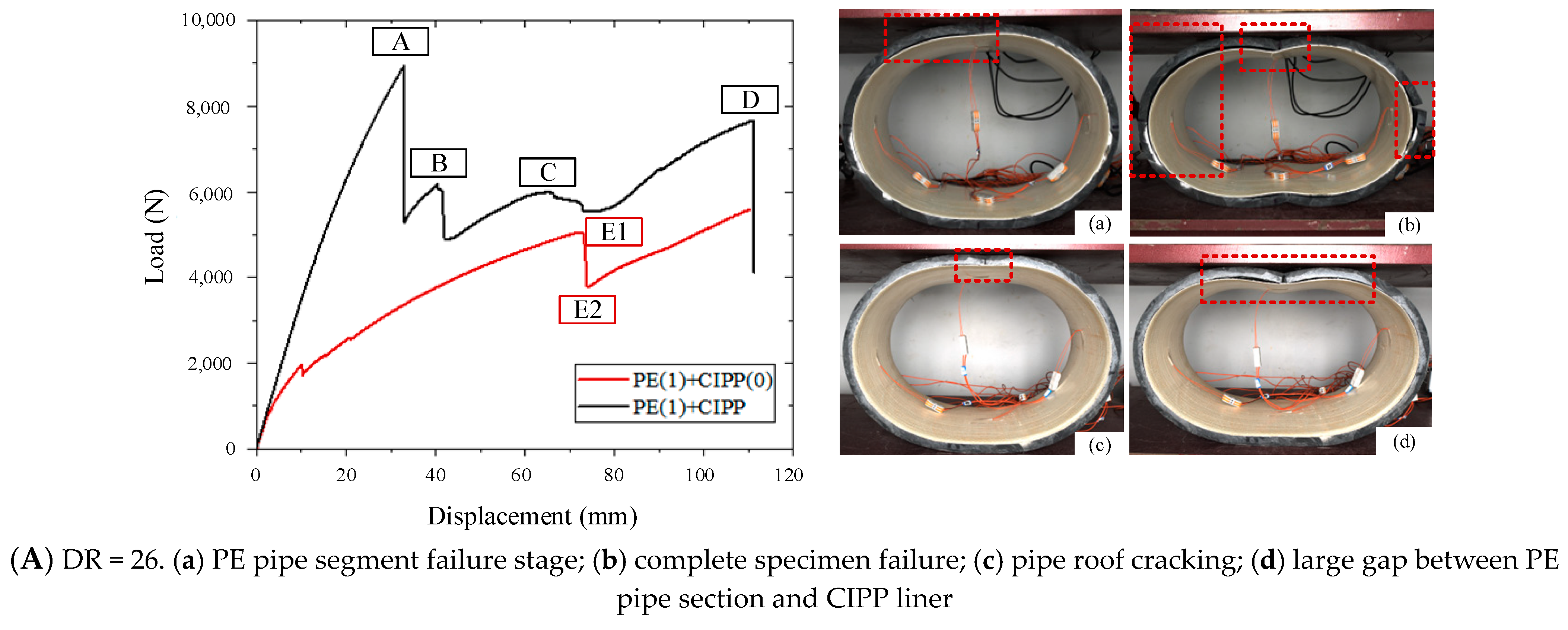
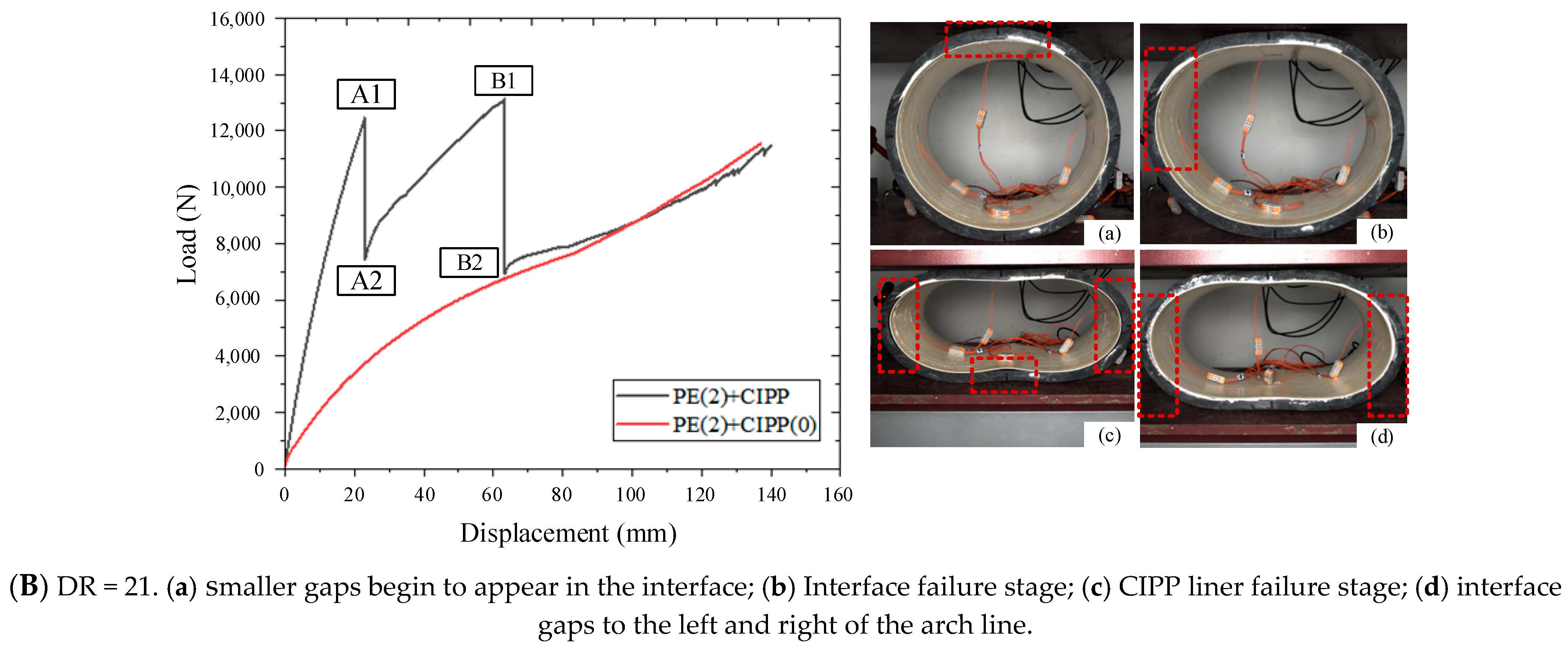
3.4. The Effect of the Interface Bond on the Bearing Capacity of PE Pipe–CIPP Liner
3.5. The Effect of Initial Ellipticity on the Bearing Capacity of PE Pipe–CIPP Liner
4. Ring Stiffness Prediction Model for PE Pipe–CIPP Liner
5. Conclusions
- CIPP technology significantly enhances the bearing capacity of PE pipe segments, with load increases ranging from 200% to 500%, inversely related to the DR value. The composite structure exhibits distinct load–displacement stages: elastic deformation, interface failure, CIPP liner failure, and brittle fracture of the PE pipe segment concentrated at the top, bottom, and arch line.
- Higher DR values result in lower stiffness, increasing susceptibility to cracking and CIPP liner bulging under load. Initial ovality compromises the composite structure’s load-bearing performance, making the original pipe segment more vulnerable to damage.
- Bonded composite structures initially show superior load-bearing capacity compared to tightly fitted structures, although stability decreases post-interface failure, leading to similar ultimate load-bearing capacities.
- The derived ring stiffness calculation formula from the composite beam model accurately predicts ring stiffness for interface-bonded composite materials, aligning well with experimental data.
Author Contributions
Funding
Data Availability Statement
Acknowledgments
Conflicts of Interest
References
- Ministry of Housing and Urban Rural Development. The 14th National Planning for Urban Infrastructure Construction; MHURD: Beijing, China, 2022.
- Yu, S.; Park, Y.; Hyun, S.; Park, K. Numerical simulations on shapes and materials and deterioration model of flexible sewer systems. Desalination Water Treat. 2015, 54, 1290–1298. [Google Scholar] [CrossRef]
- Spangler, M.G. The Structural Design of Flexible Pipe Culverts; Iowa Engineering Experiment Station: Ames, IA, USA, 1941. [Google Scholar]
- Watkins, R.K.; Spangler, M.G. Some characteristics of the modulus of passive resistance of soil: A study in similitude. In Proceedings of the Thirty-Seventh Annual Meeting of the Highway Research Board, Washington, DC, USA, 6–10 January 1958. [Google Scholar]
- Spangler, M.G. Soil Engineering, 4th ed.; Harper & Row: Manhattan, NY, USA, 1982. [Google Scholar]
- Howard, A.K. The USBR Equation for Predicting Flexible Pipe Deflection. Int. J. Quantum Chem. 1981, 3, 21–27. [Google Scholar]
- Jeyapalan, J.K.; Boldon, B.A. Performance and Selection of Rigid and Flexible Pipes. J. Transp. Eng. 1986, 112, 507–524. [Google Scholar] [CrossRef]
- Jeyapalan, J.K.; Ethiyajeevakaruna, S.W.; Boldon, B.A. Behavior and design of buried very flexible plastic pipes. J. Transp. Eng. 1987, 113, 642–657. [Google Scholar] [CrossRef]
- Cholewa, J.A.; Brachman, R.W.I.; Moore, I.D. Response of a polyvinyl chloride water pipe when transverse to an underlying pipe replaced by pipe bursting. Can. Geotech. J. 2009, 46, 1258–1266. [Google Scholar] [CrossRef]
- Saiyar, M.; Ni, P.; Take, W.A.; Moore, I.D. Response of pipelines of differing flexural stiffness to normal faulting. Géotechnique 2016, 66, 275–286. [Google Scholar] [CrossRef]
- Ni, P.; Mangalathu, S.; Yi, Y. Fragility analysis of continuous pipelines subjected to transverse permanent ground deformation. Soils Found. 2018, 58, 1400–1413. [Google Scholar] [CrossRef]
- Liu, J.; Xie, Q.; Ye, M.; Ni, P.; Qin, X. Response of UPVC pipes buried in sand under lateral ground movement. Tunn. Undergr. Space Technol. 2023, 138, 105177. [Google Scholar] [CrossRef]
- Takahashi, Y.; Deguchi, T.; Li, L.; Yamada, K. A Study on the Bedding Effects of the Deteriorated Existing Pipe on the Flexible Rehabilitated Pipe and its Mechanism. J. Jpn. Sew. Work. Assoc. 2002, 39, 103–115. [Google Scholar]
- Gumbel, J.; Spasojevic, A.; Mair, R. Centrifuge modelling of soil load transfer to flexible sewer liners. In New Pipeline Technologies, Security, and Safety; American Society of Civil Engineers: Reston, VA, USA, 2003; pp. 352–362. [Google Scholar]
- Hsu, J.M.; Shou, K.J. Experimental study of the separated joint of an underground pipeline rehabilitated by cured-in-place pipe. Undergr. Space 2022, 7, 543–563. [Google Scholar] [CrossRef]
- Allouche, E.; Alam, S.; Simicevic, J.; Sterling, R.; Condit, W.; Matthews, J.; Selvakumar, A. A pilot study for retrospective evaluation of cured-in-place pipe (CIPP) rehabilitation of municipal gravity sewers. Tunn. Undergr. Space Technol. 2014, 39, 82–93. [Google Scholar] [CrossRef]
- Zhang, X.; Fang, H.; Hu, Q.; Ma, B.; Hu, S.; Du, M.; Du, X.; Yang, K.; Li, B.; Shi, M. Mechanical performance of corroded reinforced concrete pipelines rehabilitated with sprayed-on cementitious liners subjected to combined loads. Tunn. Undergr. Space Technol. 2022, 120, 104266. [Google Scholar] [CrossRef]
- Argyrou, C.; Bouziou, D.; O’Rourke, T.D.; Stewart, H.E. Retrofitting pipelines with cured-in-place linings for earthquake-induced ground deformations. Soil Dyn. Earthq. Eng. 2018, 115, 156–168. [Google Scholar] [CrossRef]
- Shou, K.J.; Huang, C.C. Numerical analysis of straight and curved underground pipeline performance after rehabilitation by cured-in-place method. Undergr. Space 2020, 5, 30–42. [Google Scholar] [CrossRef]
- Yang, K.; Fang, H.; Zhang, X.; Li, B.; Hu, Q. Investigation of mechanical properties of corroded concrete pipes after cured-in-place-pipe (CIPP) rehabilitation under multi-field coupling. Tunn. Undergr. Space Technol. 2022, 128, 104656. [Google Scholar] [CrossRef]
- Mogielski, K.A.; Kuliczkowski, A.; Kuliczkowska, E. Change in Toughness Parameters of Sewer Pipes Rehabilitated with Two Types of Epoxy CIPP Liners. J. Pipeline Syst. Eng. Pract. 2017, 8, 04017015. [Google Scholar] [CrossRef]
- Kuliczkowski, A.; Mogielski, K. Results of laboratory tests of concrete, vitrified clay and PVC sewer pipes with CIPP liners. Struct. Environ. 2012, 4, 23–34. [Google Scholar]
- Hu, H.; Niu, F.; Dou, T.; Zhang, H. Rehabilitation effect evaluation of CFRP-lined prestressed concrete cylinder pipe under combined loads using numerical simulation. Math. Probl. Eng. 2018, 2018, 3268962. [Google Scholar] [CrossRef]
- Yan, X.; Deng, C.; Zhao, Y.; Liu, H.; Mei, S. Mechanical Performance Study of Pipe-Liner Composite Structure Based on the Digital Image Correlation Method. IEEE Trans. Instrum. Meas. 2022, 72, 3504212. [Google Scholar] [CrossRef]
- ISO 4427-2:2019; Plastics piping systems for water supply, and for drainage and sewerage under pressure—Polyethylene (PE)—Part 2: Pipes. International Organization for Standardization: Geneva, Switzerland, 2019.
- ISO 11295:2022; Plastics piping systems used for the rehabilitation of pipelines—Classification and overview of strategic, tactical and operational activities. International Organization for Standardization: Geneva, Switzerland, 2022.
- ISO 11296-3:2018; Plastics piping systems for renovation of underground non-pressure drainage and sewerage networks—Part 3: Lining with a cured-in-place pipe. International Organization for Standardization: Geneva, Switzerland, 2018.


| Group | Test No. | PE Pipe | Other Processing | Quantity | |||
|---|---|---|---|---|---|---|---|
| DN (mm) | Length (mm) | Diameter-Thickness Ratio (DR) | Additional Treatments | CIPP Liner | |||
| T0 | PE(1) | 400 | 300 | 26 | / | × | 3 |
| PE(2) | 400 | 300 | 21 | / | × | 3 | |
| PE(3) | 400 | 300 | 17 | / | × | 3 | |
| T1 | PE(1) + CIPP | / | 300 | 92.5 | / | √ | 3 |
| PE(2) + CIPP | / | 300 | 92.5 | / | √ | 3 | |
| PE(3) + CIPP | / | 300 | 92.5 | / | √ | 3 | |
| T2 | PE(1) + CIPP(0) | / | 300 | 92.5 | PE Film | √ | 1 |
| PE(2) + CIPP(0) | / | 300 | 92.5 | PE Film | √ | 1 | |
| T3 | PE(2) + CIPP(5%) | / | 300 | 92.5 | 5% Ovality | √ | 1 |
| Sample Identification | Loads Corresponding to Pipes with 3.0% Deformation F (N) | 3.0% Deformation of the Pipe Corresponding to the Deformation y (mm) | Test Ring Stiffness Si (kN/m2) | Average Ring Stiffness S (kN/m2) | Bearing Capacity Increment (%) |
|---|---|---|---|---|---|
| PE(1) | 150.89 | 11.08 | 3.56 | 3.74 | / |
| PE(1) | 656.58 | 3.82 | |||
| PE(1) | 660.50 | 3.84 | |||
| PE(1) + CIPP-1 | 3540.56 | 10.84 | 21.07 | 21.98 | 487.7% |
| PE(1) + CIPP-2 | 3740.56 | 22.25 | |||
| PE(1) + CIPP-3 | 3802.25 | 22.62 | |||
| PE(2) | 1638.88 | 10.85 | 9.74 | 9.75 | / |
| PE(2) | 1643.12 | 9.77 | |||
| PE(2) | 1640.12 | 9.75 | |||
| PE(2) + CIPP-1 | 6802.32 | 10.62 | 41.31 | 41.35 | 324.1% |
| PE(2) + CIPP-2 | 6642.79 | 40.34 | |||
| PE(2) + CIPP-3 | 6982.32 | 42.4 | |||
| PE(3) | 2752.76 | 10.58 | 16.78 | 16.81 | / |
| PE(3) | 2758.21 | 16.82 | |||
| PE(3) | 2762.48 | 16.84 | |||
| PE(3) + CIPP-1 | 10,698.29 | 10.36 | 66.6 | 66.51 | 295.66% |
| PE(3) + CIPP-2 | 10,452.64 | 65.08 | |||
| PE(3) + CIPP-3 | 10,898.18 | 67.85 |
| Sample No. | Loads Corresponding to Pipes with 3.0% Deformation F (N) | 3.0% Deformation of the Pipe Corresponding to the Deformation y (mm) | Test Ring Stiffness Si (kN/m2) | Bearing Capacity Increment (%) |
|---|---|---|---|---|
| PE(1) + CIPP(0) | 1799.08 | 10.84 | 10.7 | 203.12% |
| PE(2) + CIPP(0) | 3830.2 | 10.61 | 23.28 | 138.77% |
| Sample No. | Test Ring Stiffness (kN/m2) | Calculated Ring Stiffness (kN/m2) | Error (%) |
|---|---|---|---|
| PE(1) + CIPP | 21.98 | 21.39 | 2.68% |
| PE(2) + CIPP | 41.18 | 45.28 | −9.96% |
| PE(2) + CIPP | 66.51 | 72.67 | −9.26% |
Disclaimer/Publisher’s Note: The statements, opinions and data contained in all publications are solely those of the individual author(s) and contributor(s) and not of MDPI and/or the editor(s). MDPI and/or the editor(s) disclaim responsibility for any injury to people or property resulting from any ideas, methods, instructions or products referred to in the content. |
© 2024 by the authors. Licensee MDPI, Basel, Switzerland. This article is an open access article distributed under the terms and conditions of the Creative Commons Attribution (CC BY) license (https://creativecommons.org/licenses/by/4.0/).
Share and Cite
Wang, X.; Zeng, C.; Yan, X.; Zhang, P. Study on the Bearing Capacity of the Polyethylene Pipe–Cured-In-Place Pipe Liner Composite Structure under External Pressure. Buildings 2024, 14, 2253. https://doi.org/10.3390/buildings14072253
Wang X, Zeng C, Yan X, Zhang P. Study on the Bearing Capacity of the Polyethylene Pipe–Cured-In-Place Pipe Liner Composite Structure under External Pressure. Buildings. 2024; 14(7):2253. https://doi.org/10.3390/buildings14072253
Chicago/Turabian StyleWang, Xinyi, Cong Zeng, Xuefeng Yan, and Peng Zhang. 2024. "Study on the Bearing Capacity of the Polyethylene Pipe–Cured-In-Place Pipe Liner Composite Structure under External Pressure" Buildings 14, no. 7: 2253. https://doi.org/10.3390/buildings14072253