Article

An Improved Numerical Simulation Method for Rockbolt Fracture and Its Application in Deep Extra-Thick Coal Seam Roadways

1
Shandong Key Laboratory of Civil Engineering Disaster Prevention and Mitigation, Shandong University of Science and Technology, Qingdao 266590, China
2
College of Pipeline and Civil Engineering, China University of Petroleum (East China), Qingdao 266580, China
3
Shandong Xinjulong Energy Co., Ltd., Heze 274918, China
*
Author to whom correspondence should be addressed.
Buildings 2024, 14(8), 2373; https://doi.org/10.3390/buildings14082373
Submission received: 21 June 2024 / Revised: 27 July 2024 / Accepted: 30 July 2024 / Published: 1 August 2024

Abstract

:
An improved method for rockbolt fracture is proposed in this paper to determine the exact fracture position of rockbolts simulated using cable structural elements (cableSELs) in FLAC3D. This method employs the total elongation of the free segment of the rockbolt as the fracture criterion. The maximum deformation position is identified by comparing the length of each cableSEL in the free segment leading to the fracture. The simulation results validated through a rockbolt tensile test closely match actual conditions. The proposed method was used to optimize the roadway support in deep extra-thick coal seams (DECSs). Optimized parameters were obtained by simulating and analyzing different lengths and spacings of rockbolts and anchor cables. The field implementation conducted shows that the optimized deformation and support strength of the roadway meet safety needs.

1. Introduction

Coal mining in many regions of China continues to expand deeper underground with the gradual depletion of shallow coal resources [1,2,3,4]. More than 50 mines have been excavated to depths exceeding 1000 m, with the deepest reaching 1510 m [5]. In deep mining, the stability and safety of coal roadways are crucial [6,7]. Compared to shallow coal roadways, deep coal roadways suffer higher ground stress and increased mining-induced disturbances, resulting in greater deformations [8,9]. Rockbolts and anchor cables are the primary forms of roadway support [10,11]. Under these conditions, the issue of rod fracture has become increasingly prominent [12,13,14], with the fracture rate of anchor cables in some roadways even reaching 65% [15]. Therefore, it is essential to consider the issues of fractures in rockbolts and anchor cables when studying support in deep coal roadways.
Numerical simulation is an essential method for studying roadway support. FLAC3D 5.0 (Itasca Consulting Group, Inc., Minneapolis, MN, USA) is a powerful numerical calculation software widely accepted and applied in geotechnical engineering [16]. The cable structural elements (cableSELs) can easily simulate the axial anchoring effect of the rockbolt and anchor cable, making them suitable for engineering-scale simulation analysis [17,18]. However, the cableSELs provided by FLAC3D 5.0 do not fracture and will always withstand axial forces. As a result, the fracture of rockbolts is not considered in most FLAC3D simulations, leading to high support strength in the simulations and reducing their reliability. Only a few scholars have recognized this issue. They conducted research on the failure of the rockbolt based on the FLAC3D secondary development platform. Liu et al. [19] implemented axial force loss of rockbolts caused by blasting in FLAC3D. Li et al. [20] developed a method for rockbolt fracture using the total elongation of the free segment as the criterion in FLAC3D. However, the study did not provide further explanation on how to determine the exact fracture position of the rockbolt. Therefore, improved numerical methods are needed to achieve more accurate simulations.
Thick (3.5 m ≤ thickness ≤ 8.0 m) and extra-thick (thickness ≥ 8.0 m) coal seams are widely distributed in deep coal deposits [21,22,23]. The roadway can be arranged along the floor of the coal seam to form a top coal roadway [24]. Currently, research on roadway support primarily addresses thick coal seams [25,26,27,28], with relatively less focus on extra-thick coal seams. Studies have determined optimized support schemes for roadways in thick coal seams by simulating different parameters of rockbolts or anchor cables. These results provide some foundation for supporting roadways in deep extra-thick coal seams (DECSs). As the thickness of the coal seam increases, so does the thickness of the roof coal. This can lead to a decreased stability of the coal seam and the potential presence of weak interlayers [29]. Without effective control, significant roof subsidence and even roof collapse accidents may occur [30,31,32]. Therefore, it is necessary to further explore the reasonable support parameters for roadways in DECSs.
In response to the above issues, this research first improved the simulation method by designing a program to determine the exact fracture position of the rockbolt, which was then validated through tensile tests. Subsequently, an optimization study on the roadway support in DECSs was conducted based on the improved method. The optimized parameters obtained were then implemented in the field. This simulation method and application results are expected to provide a reference for related support engineering.

2. Design and Validation of the Rockbolt Fracture Program

An improved method for rockbolt fracture is proposed to determine the precise fracture position of the simulated rockbolt. The goal of this method is to achieve fracture at the position of maximum deformation of the rockbolt.

2.1. The Principle of Tensile Fracture of Rockbolts

Rockbolts are typically composed of free segments, anchorage segments, and anchor heads (Figure 1). Considering the fact that the free segment lacks the constraint of anchoring material, its deformation under load is, in general, significantly larger than that of the anchorage segment. Therefore, the total elongation of the free segment is used as the fracture criterion (Equation (1)). Building upon this, the maximum deformation position of the rockbolt is further determined, thus achieving fracture.
S f > S max = ( 1 + δ ) × l f
where Sf, Smax, and lf represent the length, maximum length, and original length of the rockbolt’s free segment (m), respectively; δ is the elongation ratio at rockbolt fracture.
The principle of rockbolt fracture is shown in Figure 1. In FLAC3D, a cableSEL is a straight segment of uniform cross-sectional and material properties located between two nodes. A rockbolt (anchor cable) typically comprises multiple cableSELs. When the rockbolt reaches the fracture criterion, the maximum deformation position can be determined by comparing the length of each cableSEL within the free segment. At this point, the elastic modulus (E), the tensile yield strength (Ft), and the cross-sectional area (A) of the cableSEL with the largest deformation are set to 0 to achieve fracture.

2.2. Rockbolt Fracture Program Design

Next, we design a specific implementation process for rockbolt fracture in FLAC3D (Figure 2). We use a specific rockbolt in the model as an example to facilitate the explanation. In the rockbolt’s free segment, j denotes the serial number of the cableSEL. Assuming that there are n cableSELs in the free segment, the value range of j is 1, 2, …, n. After inputting cableSELs and other parameters, we can proceed to the FLAC3D main program.
(1)
When reaching step i (i = 1, 2, 3, …), we first check whether the calculation has converged. If it has, we end the calculation.
(2)
If it has not converged, we enter the rockbolt fracture program, where the following steps are performed:
➀ The length Uij of each cableSEL in the free segment is obtained.
➁ The value Si for the sum of all cableSEL lengths in the free segment is calculated.
➂ We check if the rockbolt meets the fracture criterion SiSmax. If not, we proceed directly to step (i + 1).
➃ If the fracture criterion is met, the length Uij of each cableSEL in the free segment is compared, and the serial number of the cableSEL with the largest length is identified using an “if-endif” control statement.
➄ We check if the elastic modulus E of the cableSEL with the largest length is 0. If it is 0, we proceed directly to step (i + 1). This step aims to reduce the number of repetitive commands and enhance computational efficiency. Its presence or absence does not affect the final calculation result.
➅ If the elastic modulus E of the cableSEL with the largest length is not 0, the command “E = 0, Ft = 0, A = 0” is applied to this cableSEL to induce fracture at that position. Then, we proceed to step (i + 1).

2.3. Rockbolt Fracture Program Validation

2.3.1. Design of Rockbolt Tension Test

A rockbolt tensile simulation test was performed to validate the correctness of the rockbolt fracture program. The simulation test object is an actual mine rockbolt with a diameter of 22 mm, a length of 2.2 m, an elastic modulus of 2 × 10¹¹ Pa, a yield axial force of 228 kN, and a fracture elongation of 15%. The established model for the tensile test of the rockbolt is shown in Figure 3. The rockbolt model is divided into 22 cableSELs to improve simulation accuracy, each with a length of 0.1 m. The cable serial numbers range from 1 to 22 from left to right and can be represented by component identification (CID) numbers. The actual effective length of the rockbolt is 2 m (CID 2–21), with a cable (CID 1 and 22) at each end serving as the clamping component.
The rockbolt fracture program in Section 2.2 is embedded, and the maximum length of the rockbolt’s free segment is set as Smax = 2 × (1 + 0.15) = 2.3 m. During the experiment, the right end of the rockbolt is fixed, and the left end is stretched to the left at a constant speed of 1 × 10⁻⁵ m/step. One should monitor the axial force and length of each cableSEL, stop after 35,000 steps, and view the results.

2.3.2. Analysis of Test Results

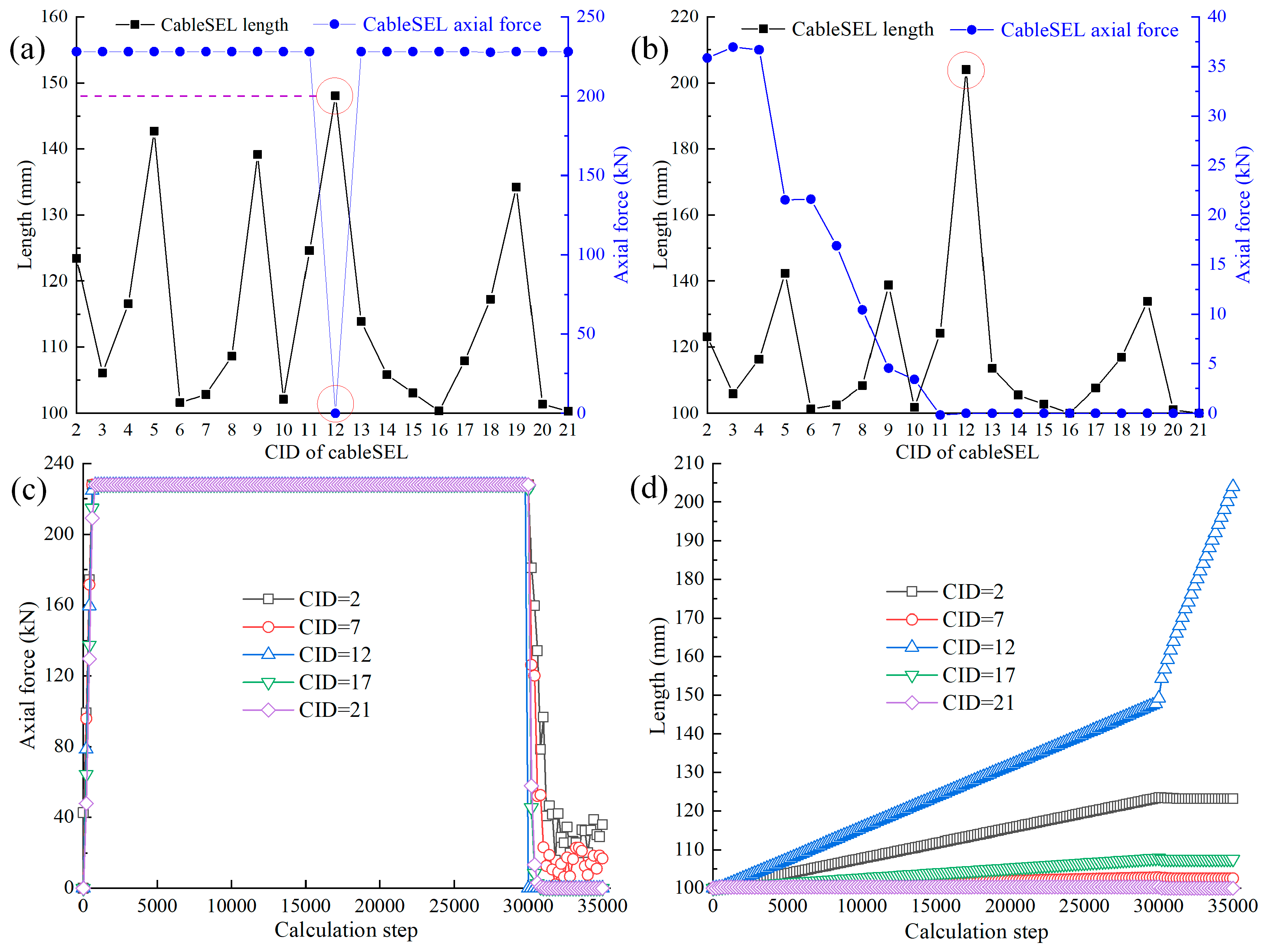
It was found by viewing the axial forces on each cableSEL that the force on CID12 at step 30,010 first dropped to zero (Figure 4a), indicating a fracture. At this point, the length of the rockbolt’s free segment is 2.3 m, which meets the set fracture condition. A comparison of the lengths of each cableSEL reveals that CID12 has the maximum length, measuring 148.1 mm. This indicates that the fracture program achieves the rockbolt fracture at the position of maximum deformation.
The forces and deformation of the rockbolt after fracture were further analyzed. Several representative cableSELs were selected for presentation and explanation due to their large number. Figure 4c displays the rockbolt forces, showing that after CID12 fractured, the forces on the other cableSELs rapidly dropped to zero, except for those near the tensile end which retained a small amount of force. Figure 4d illustrates the rockbolt deformation after CID12 fractured, whereby only its length continued to increase while the lengths of the other cableSELs remained unchanged. Figure 4b shows the axial force and length of each cableSEL at the end of the calculations, among which the length of the CID12 has reached 204 mm.
The position of the rockbolt fracture and its post-fracture performance are consistent with the expected results, validating the correctness of the rockbolt fracture program.

3. Engineering Simulation Applications

3.1. Engineering Background

3.1.1. Engineering Geology and Original Support

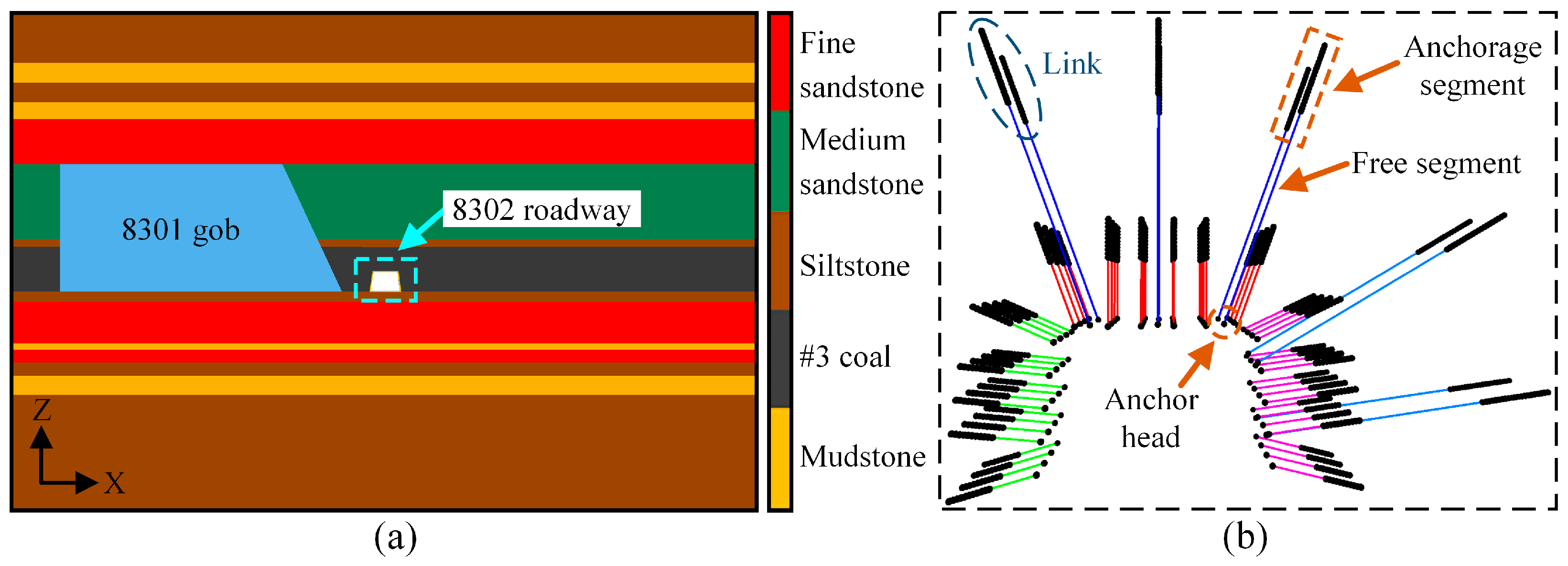
Taking Xinjulong coal mine as the background, research on roadway support in DECSs was carried out. The mine is located in Longgu town, He’ze city, Shandong Province, China. The average thickness of the mined #3 coal seam is 9.0 m. The 8302 transportation roadway, which is 912.71–963.36 m deep, represents a typical roadway in DECSs. The roadway is arranged along the floor of the #3 coal seam, as shown in Figure 5a. The geological stratigraphic column of that seam is displayed in Figure 5c. The mechanical parameters of the surrounding rock are detailed in Table 1. The bulk modulus and shear modulus were calculated using the corresponding formula [33], and the remaining rock parameters were obtained from rock mechanics tests.
The roadway is an isosceles trapezoid with a roof width of 5.1 m, a base width of 6.1 m, and a height of 4.15 m. The original support parameters of the roadway are shown in Figure 5b. The diameter of the rockbolts is 22 mm, the row spacing is 1.0 m, and they are used together with W-shaped steel strips. The diameter of the anchor cables is 22 mm, and they are arranged between the W-shaped steel strips with a row spacing of 2.0 m.

3.1.2. Analysis of Roadway Deformation and Support

The roadway deformation at a distance of 60 m from the starting point was monitored using the cross-measurement method (Figure 6a). The results show that the roadway experienced rapid deformation within 10 days after excavation, with rates of 7.0 mm/day for the roof and 5.9 mm/day for both sidewalls. Thereafter, the deformation rate of the roadway gradually decreased. By the 125th day, the roof and both sidewalls had experienced deformations of 145 mm and 131 mm, respectively. The deformation of both sidewalls was relatively smaller and had largely stabilized, whereas the roof experienced significant subsidence and continued to show an increasing trend. Moreover, field support found that the roof rockbolt trays had been twisted (Figure 6b), posing a risk of further rod failure. The above situation indicates that the original roof support is inadequate, making it necessary to redesign the support parameters to better adapt to the geological conditions.

3.2. Engineering Simulation Test Design

The length and spacing parameters of the roof rockbolts and anchor cables were studied to optimize the roadway support. The suitable range of roof support parameters was calculated based on the rockbolt and anchor cable support theory. Accordingly, a simulation test scheme was then developed.

3.2.1. Support Mechanisms and Parameter Ranges

Figure 7 demonstrates the combined support mechanism of rockbolts and anchor cables in the roadways of the DECSs. Rockbolts reinforce the shallow surrounding rock, creating a compression reinforcement zone, while anchor cables are securely anchored in the stable rock layer to provide suspension and tension support for the reinforced zone. The stability of the roadway surrounding the rock is ensured through the synergy of these two elements [34].
Based on reinforced arch theory [35,36], the formula for roof rockbolt length is
L = b tan α + a tan α + 0.15
where L is the rockbolt length (m); b is the thickness of the reinforced arch, generally 0.8–1.2 m and 0.8 m here; tan α is the tangent value of the control angle of the rockbolt to the fractured rock mass, with α = 45°; and a is the rockbolt spacing, which is 0.9 m here.
The formula for the rockbolt spacing is
D 0.5 L
where D is the rockbolt spacing (m); L is the rockbolt length; and according to Equation (2), when b = 1.2 m, L = 2.25 m.
Based on suspension theory [37,38], the formula for roof anchor cable length is
X = X 1 + X 2 + X 3
where X is the anchor cable length (m); X1 is the exposed length of the anchor cable, taken as 0.15 m; X2 is the thickness of the suspended rock layer, observed to be 4.3 m from roof drilling; and X3 is the anchoring length of the anchor cable, taken as a minimum of 1.5 m.
The formula for the anchor cable spacing is
S = 3 [ F ] 4 B 2 γ k
where S is the anchor cable spacing (m); [F] represents the ultimate breaking force of a single anchor cable, taken as 530 kN; B is the roadway width, taken as 5.1 m; γ is the bulk density of the overlying rock layer, taken as 13 kN/m3; and k is the safety factor, taken as 0.5.
It was calculated that the minimum required length for the roof rockbolt should be 1.85 m, and the rockbolt spacing should not exceed 1.13 m. Additionally, the length of the roof anchor cable should be greater than 5.95 m, and the anchor cable spacing should not exceed 2.35 m.

3.2.2. Support Parameter Test Scheme

The test parameters were set as in Table 2 according to the support parameter range calculated in Section 3.2.1. The control variable method was adopted and the original scheme was employed as the initial support parameters. The length and spacing of the rockbolt as well as the length and spacing of the anchor cable were, respectively, studied in turn. The optimization result of the previous parameter was taken as the fixed value to study the next parameter. Finally, all the optimized parameters were obtained.

3.3. Modeling of the Roadway Surrounding Rock and Support

The numerical model was constructed using FLAC3D and has dimensions of 150 m (X) in width, 100 m (Z) in height, and 12 m (Y) in thickness, as shown in Figure 8a. The numerical model is divided into a total of 61,704 units and 66,450 nodes. The horizontal displacement constraint is applied to the front, back, left, and right sides of the model, while the full displacement constraints are applied to the bottom. A uniform load of 22.7 MPa is applied to the top part of the model to simulate the effect of strata weight [39]. The lateral pressure coefficients in the X and Y directions are set as 1.7 and 1.0, respectively, to simulate the effect of horizontal stress [40]. The Mohr–Coulomb model is adopted for the strata [41], and the parameters of the strata are taken according to Table 1. The double-yield model is used to simulate the strain-hardening behavior of the gob material [42,43]. Based on the Salamon theoretical model [44], the double-yield model parameters obtained using the trial-and-error method [45] are shown in Table 3. The range of roadway excavation (Y) is 3.5–8.5 m.
The cableSELs are used to model rockbolts and anchor cables, and the numerical model of the support is illustrated in Figure 8b. The rockbolts are arranged in four rows, beginning at Y = 4.5 m, with a row spacing of 1 m. The anchor cables are arranged in two rows, beginning at Y = 5.0 m, with a row spacing of 2 m. The parameters of the rockbolt and anchor cable models are presented in Table 4.
The length of each cableSEL forming the rod is set to 0.1 m to enhance simulation accuracy. For example, a 2.8 m rockbolt consists of 28 cableSELs, while an 8.3 m anchor cable consists of 83 cableSELs. The implementation mechanism of each part of the support rod is as follows. The anchor head is constructed by establishing a rigid connection between the node at the end of the rod and the surrounding rock. The free segment is realized through two aspects. The first is to set the anchorage agent parameter to 0, and the second is to delete the connection between the cableSEL nodes of the free segment and the surrounding rock. The anchorage segment is assigned anchoring parameters, with the parameters of the anchorage agent detailed in Table 5. These parameters are calculated using the corresponding formulas provided in the FLAC3D manual.
The rockbolt fracture program in Section 2.2 is embedded. Of course, this program is also applicable to anchor cables. For different rod lengths, the anchorage length of the rockbolts is set to 1 m, while the anchorage length of the anchor cables is set to 2 m. Using a 1.9 m rockbolt as an example, the fracture criterion is (1.9−1) × 0.15 = 0.135 m. The fracture criteria for rods of other lengths are obtained using the same calculation rules and are not individually listed.

3.4. Analysis of Simulation Results

3.4.1. Rockbolt Length Optimization

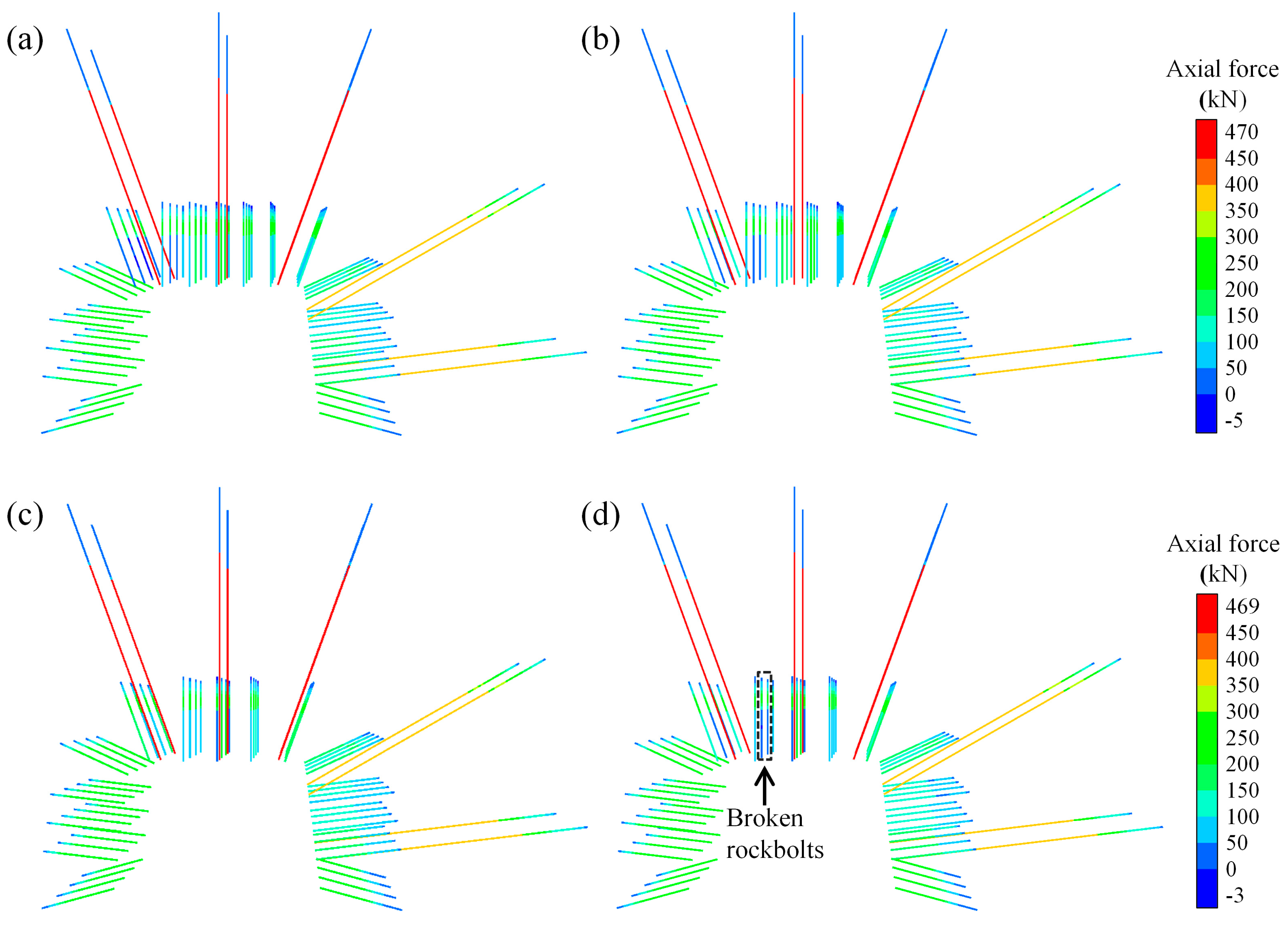
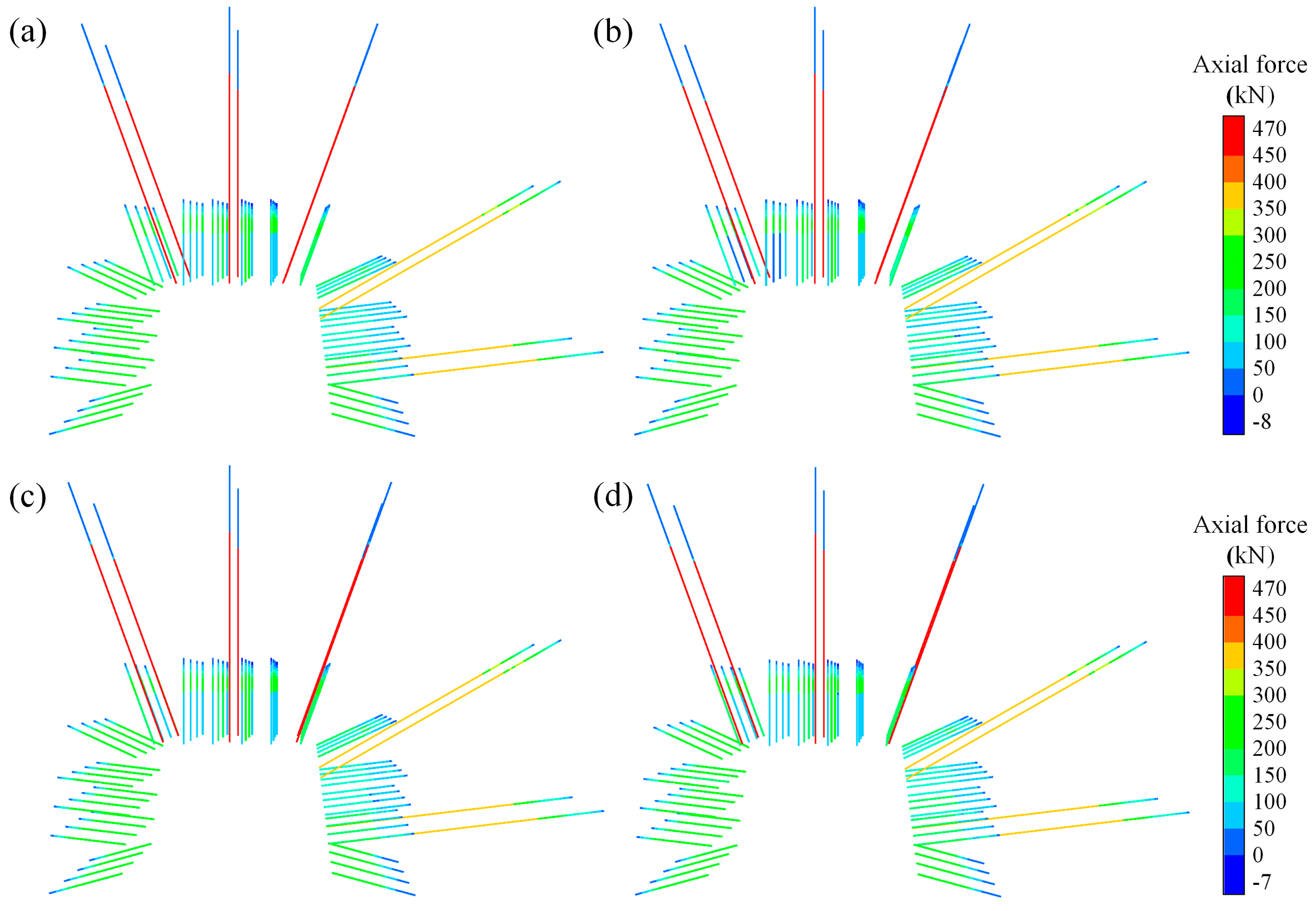
The proper length of rockbolts is an important factor in ensuring the stability of the coal seam. The relationship between the roof rockbolt length and roadway deformation is shown in Table 6, while the force and fracture conditions of the rods are depicted in Figure 9. When the rockbolt length increases from 1.9 m to 2.2 m, the roof displacement decreases by 8.1%. Simultaneously, the number of fractured rockbolts decreases from 16 to 2, and the fracture rate of the rods decreases by 18.9%. Although the roadway deformation significantly improved, rockbolt fractures still persist. When the rockbolt length increases from 2.2 m to 2.5 m, the roof displacement decreases by 4.5%, and the rods no longer fracture. When the rockbolt length exceeds 2.5 m, increasing its length does not enhance the effectiveness of roadway support. Therefore, the optimal length of the roadway roof rockbolt is 2.5 m.

3.4.2. Rockbolt Spacing Optimization

The proper spacing of rockbolts is an important factor in ensuring the stability of the reinforcement zone. The relationship between the spacing of roof rockbolts and roadway deformation is shown in Table 7, while the force and fracture conditions of the rods are depicted in Figure 10. The roof displacement remains essentially unchanged when the rockbolt spacing increases from 0.8 m to 0.9 m, and there is no fracture in the rods. When the rockbolt spacing exceeds 0.9 m, the roof deformation increases obviously with the increasing rockbolt spacing. Moreover, two rockbolts fracture when the rockbolt spacing is 1.1 m. Therefore, the optimal spacing of the roof rockbolts of roadways is 0.9 m.

3.4.3. Anchor Cable Length Optimization

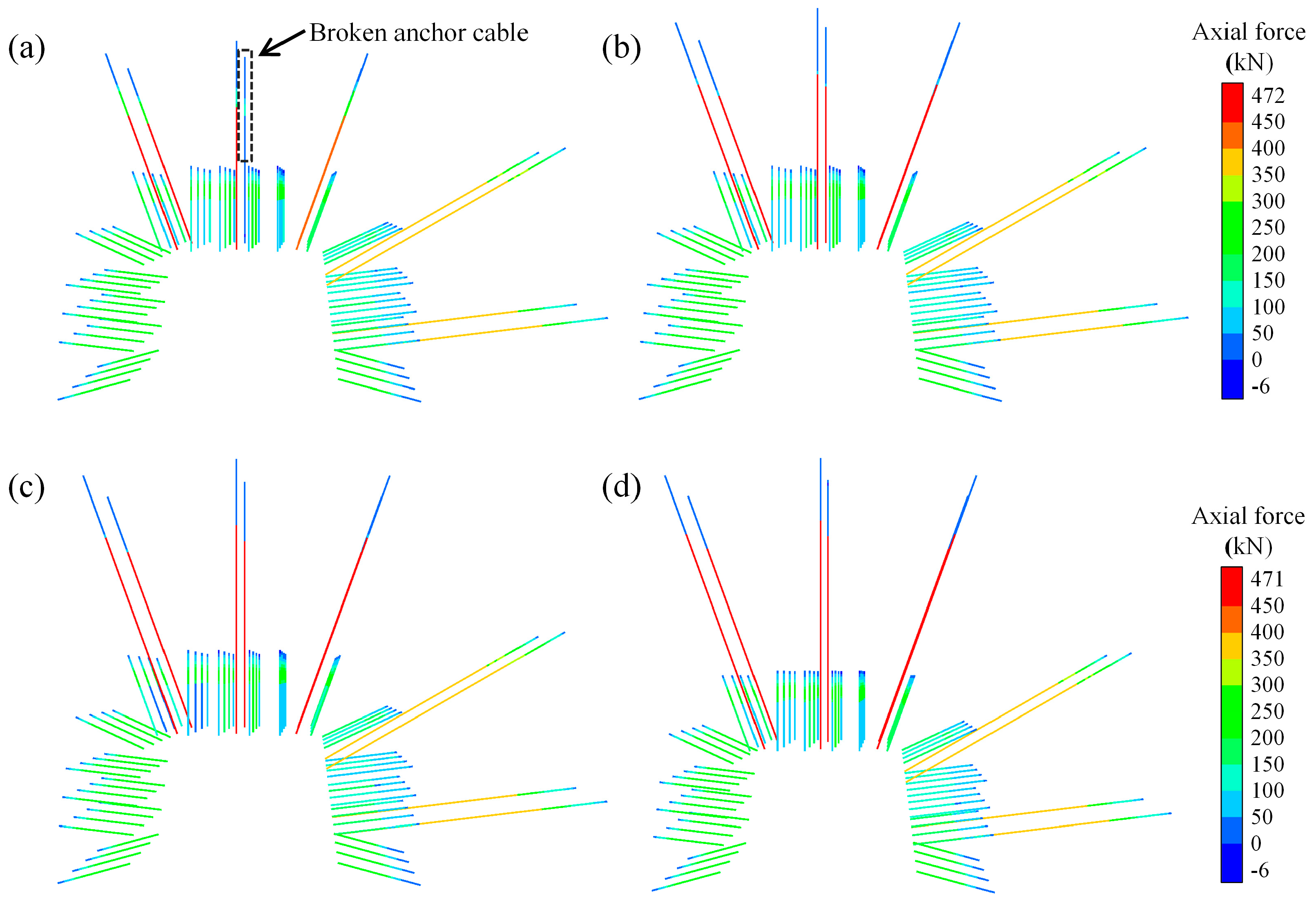
A proper length of anchor cable can effectively increase the degree of combination between deep and shallow coal and ensure the effectiveness of roadway support. The relationship between the length of the roof anchor cable and roadway deformation is shown in Table 8, while the force and fracture conditions of the rods are depicted in Figure 11. The central anchor cable of the roof fractures when the anchor cable length is 6.3 m. As the anchor cable length increases, the rods no longer fracture. Compared to an anchor cable length of 6.3 m, the roof displacement increases by 5.5%, 12.3%, and 8.4% for anchor cable lengths of 7.3 m, 8.3 m, and 9.3 m, respectively. The deformation of the roof first diminishes and then increases. This shows that after a certain anchor cable length, a longer anchor cable does not improve the support performance. Therefore, the optimal length of the anchor cable for the roadway roof is 8.3 m.

3.4.4. Anchor Cable Spacing Optimization

A proper spacing of anchor cables can ensure the stability of the coal body between the anchor cables. The relationship between the spacing of the roof anchor cables and roadway deformation is shown in Table 9, while the force and fracture conditions of the rods are depicted in Figure 12. The rods remain intact, regardless of the spacing of the anchor cables. Compared to an anchor cable spacing of 1.6 m, the roof displacement increases by 4.1%, 8.6%, and 12.9% for anchor cable spacings of 1.8 m, 2.0 m, and 2.2 m, respectively. The roof displacement gradually increases with the spacing of the anchor cables. Therefore, the optimal spacing of the anchor cables for the roadway roof is 1.6 m.

3.4.5. Analysis of the Fracture Position of Rockbolts and Anchor Cables

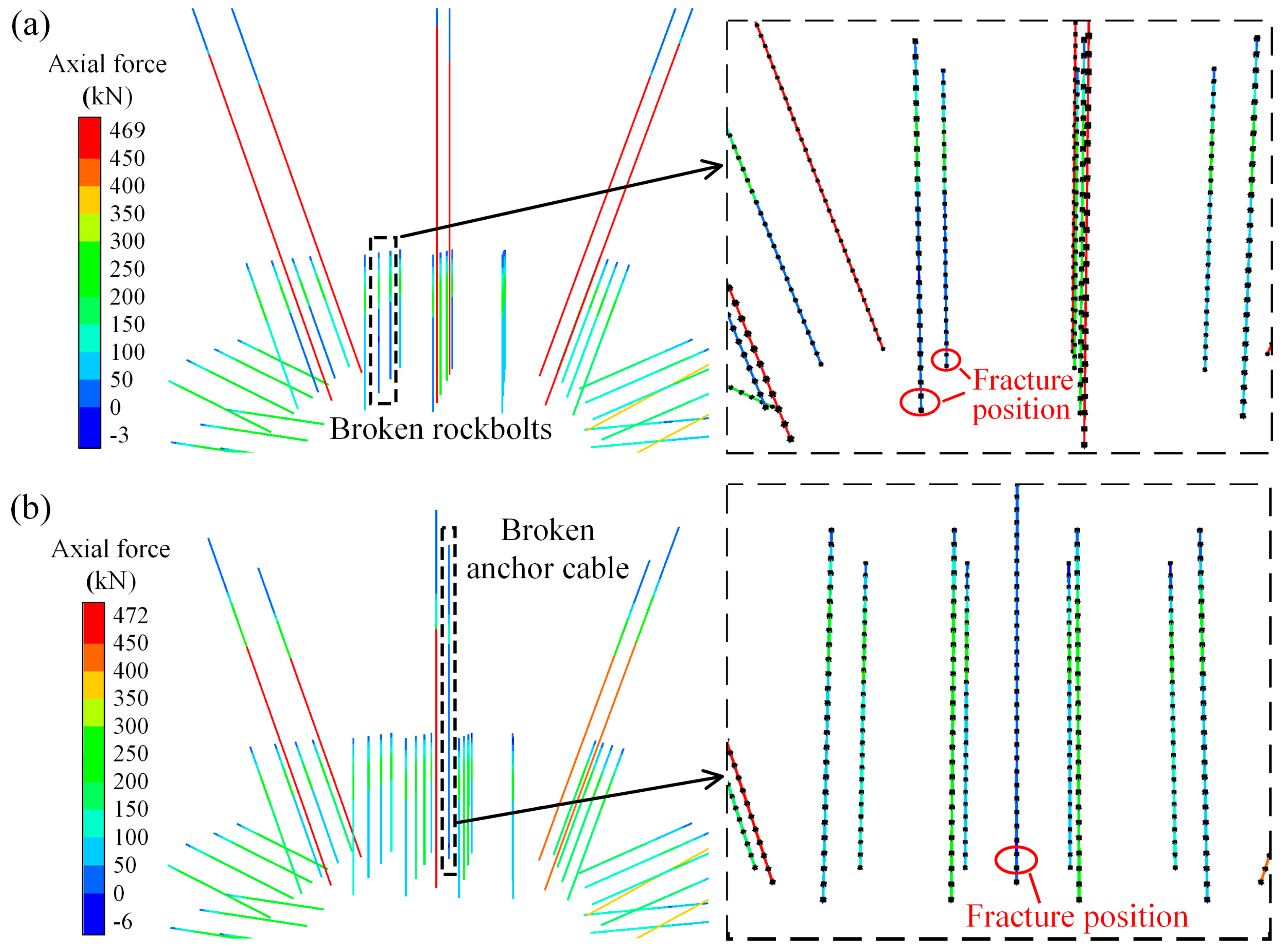
The simulation results indicate that under all parameter conditions, the fractures of rockbolts and anchor cables mainly occur at the end of the free segment near the anchor head. As an example, the simulation results for two of the parameters are illustrated in Figure 13. This indicates that under these geological conditions, the tensile fracture of the rod is mainly caused by roadway deformation. Thus, the selected support rods should have good extensibility to better enhance the supporting effect.

3.5. Optimized Roadway Support Parameters

Based on the simulation results, the optimized roadway support parameters are shown in Table 10. The differences from the original scheme are as follows: the spacing of the roof anchor cables is reduced from 1.8 m to 1.6 m, the length of the roof rockbolt is reduced from 2.8 m to 2.5 m, and the spacing of the roof rockbolts is increased from 0.85 m to 0.9 m.

4. Field Support Verification

4.1. Field Support and Monitoring Scheme

Based on the optimized support parameters, the adjusted field support is shown in Figure 14a. U-shaped anchor cable beams of 4.7 m and 2.6 m were also added to the roof and solid coal wall, respectively.
To verify the practical feasibility of the optimized support, a KJ-24 wireless mine pressure monitoring system (Shandong Cicoside Mining Safety Engineering Co., Ltd., Taian, Shandong Province, China) was used in the field for monitoring. The monitoring location is 620 m from the starting point of the roadway, and the layout of the monitoring equipment is shown in Figure 14b. The roof and floor displacements in the roadway were recorded using cross-measurement, and the displacements of both sidewalls of the roadway were measured with a laser rangefinder. The axial forces of the rockbolts and anchor cables were recorded using rockbolt (anchor cable) sensors.

4.2. Analysis of Monitoring Results

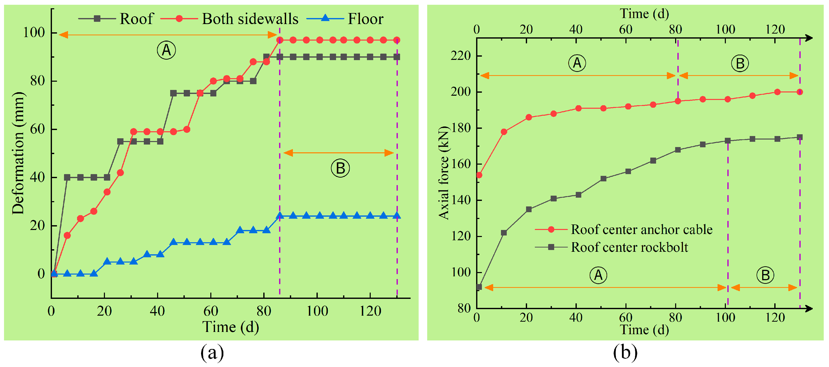
The deformation of the roadway is illustrated in Figure 15a. The deformation is divided into two stages: continuous deformation (stage Ⓐ) and stable deformation (stage Ⓑ). After 86 days of excavation, the deformation of the roadway stabilized. After 130 days of excavation, the roof and both sidewalls were deformed by 90 mm and 97 mm, respectively, which are 37.9% and 26.0% lower than those of the original scheme. The effect of roadway optimization is remarkable.
The forces of the rockbolts and anchor cables are illustrated in Figure 15b. The force of the rods experienced continuous growth (stage Ⓐ) and a stable phase (stage Ⓑ). After 130 days of excavation, the forces of the rockbolts and anchor cables were 200 kN and 175 kN, respectively, which are 38% and 61% of the maximum bearing force. The anchoring effect of the rods was fully utilized, and there was still a considerable surplus in their bearing capacity.

4.3. Analysis of Field Situation

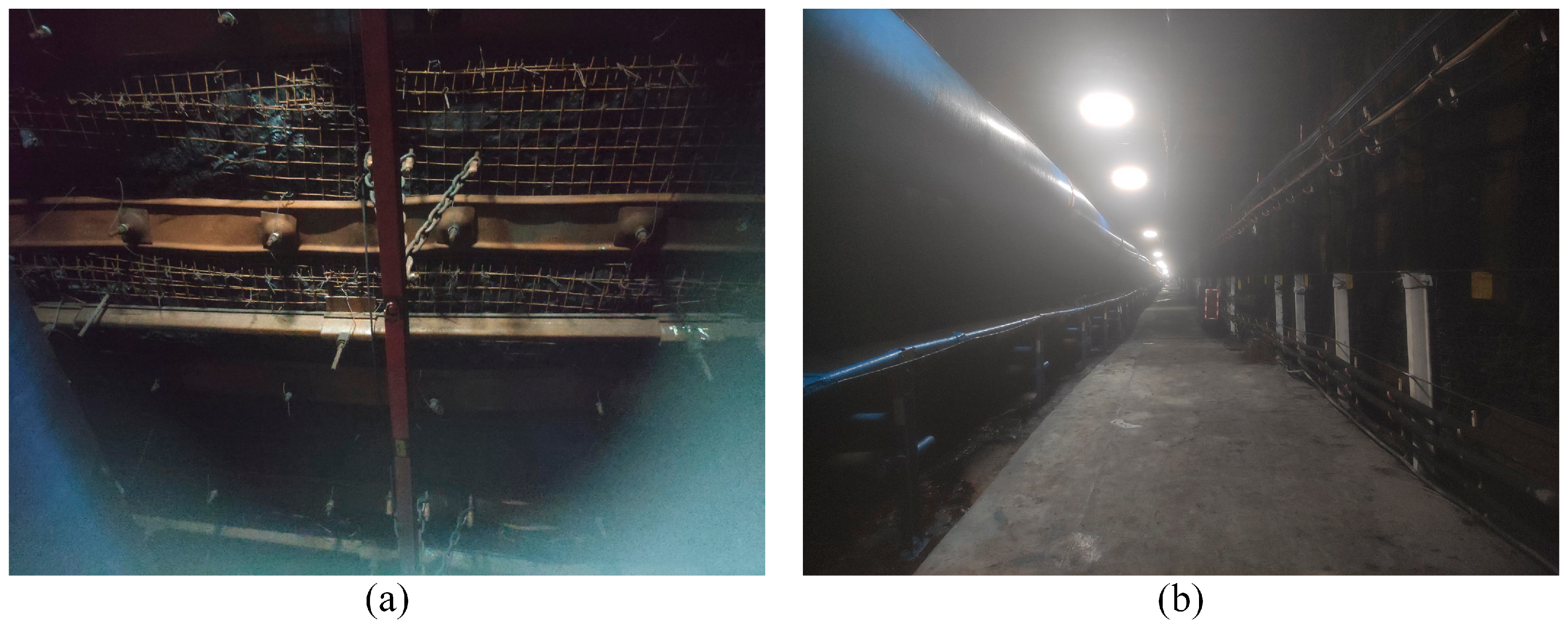
The optimization effect of the field roadway is illustrated in Figure 16. The coal mass is relatively intact, and the roof is straight. The shapes of the rockbolts and anchor cables remain normal after support. The optimized scheme is feasible and can serve as a reference for similar roadway support.

5. Discussion

(1)
With regard to rockbolts modeled by cableSELs in FLAC3D, the study by Li et al. [20] achieved their intended fracture but did not specify the exact position of the fracture. The improved method proposed in this paper achieves the fracture of the rockbolt at its position of maximum deformation, addressing this deficiency and enhancing the simulation capability of FLAC3D.
(2)
The constitutive relationships of the cableSELs determine that a rockbolt can only bear axial force [33], achieving tensile failure of the rod. Therefore, the improved simulation method is suitable for studying geological conditions where the volume deformation of the supporting rock mass is predominant. Currently, this method has been successfully applied in DECS roadways. The next step is to apply this method to other applicable rock mass types to provide support guidelines.
(3)
In practical engineering, the fracture of some rockbolts and anchor cables is not solely due to tension but results from a combination of tension, shear, and bending [46]. The pile structural elements (pileSELs) in FLAC3D can withstand the above-mentioned loads [33], providing a comprehensive reflection of the rockbolt’s stress characteristics. If it is necessary to simulate the fracture of a rod at an exact position under complex forces, one can refer to the ideas of the simulation method in this paper to correspondingly develop the pileSELs.

6. Conclusions

(1)
This paper proposes an improved method for rockbolt fracture to address the defect of unclear fracture positions in rockbolts modeled with cableSELs in FLAC3D. This method utilizes the total elongation of the rockbolt’s free segment as the fracture criterion, causing the rod to break at the point of maximum deformation. This method was validated by the rockbolt tensile test, and its simulation results are more realistic.
(2)
The optimized support parameters of the roadway roof in DECSs were obtained using the improved simulation method. Simultaneously, the simulation results show that rockbolt and anchor cable fractures occur at the end of the free segment near the anchor head. This indicates that the fracture of the rod is mainly caused by roadway deformation. The support rods used in the field should demonstrate good extensibility.
(3)
Field application verified the feasibility of the optimized support parameters. The implementation results show that the maximum roof deformation was 90 mm, which is 37.9% lower than that of the original support, and the forces on the support rods are also within the normal range. This research can provide a reference for roadway support under similar conditions.

Author Contributions

Conceptualization, B.W.; methodology, W.Z.; software, W.Z.; validation, W.Z.; formal analysis, S.Z.; investigation, Q.Z.; data curation, W.G.; writing—original draft preparation, W.Z. and S.Z.; writing—review and editing, S.Z., B.Z., W.G., T.L. and B.W.; visualization, B.Z. and B.W.; supervision, B.W.; project administration, Q.Z.; funding acquisition, T.L. All authors have read and agreed to the published version of the manuscript.

Funding

This research was funded by the National Natural Science Foundation of China (No. 41772299) and the Natural Science Foundation of Shandong Province, China (No. ZR2023ME165).

Data Availability Statement

The data presented in this study are available on request from the corresponding author. The data are not publicly available due to privacy and legal concerns.

Conflicts of Interest

Authors Bin Zhang and Weimin Gao were employed by the company Shandong Xinjulong Energy Co., Ltd. The remaining authors declare that the research was conducted in the absence of any commercial or financial relationships that could be construed as a potential conflict of interest.

References

  1. Xie, S.R.; Wu, Y.Y.; Chen, D.D.; Liu, R.P.; Han, X.T.; Ye, Q.C. Failure analysis and control technology of intersections of large-scale variable cross-section roadways in deep soft rock. Int. J. Coal Sci. Technol. 2022, 9, 19. [Google Scholar] [CrossRef]
  2. He, Z.; Xie, Z.Z.; Zhang, N.; Han, C.L.; Xiang, Z.; Yan, G.J.; Qiao, H.X.; Shao, C.Y. Research on spatiotemporal evolution law of surrounding rock fractures and hierarchical collaborative control technology in high-stress soft rock roadway: A case study. Eng. Fail. Anal. 2023, 150, 107366. [Google Scholar] [CrossRef]
  3. Meng, N.K.; Bai, J.B.; Yoo, C. Failure mechanism and control technology of deep soft-rock roadways: Numerical simulation and field study. Undergr. Space 2023, 12, 1–17. [Google Scholar] [CrossRef]
  4. Li, H.B.; Pan, W.P.; Hua, X.Z.; Luan, B.; Huang, Z.J. Instability characteristics of surrounding rock and surrounding rock control technology of deep coal roadway crossing the fault: A case study of Zhuxianzhuang coal mine. Geomat. Nat. Hazards Risk 2024, 15, 2366376. [Google Scholar] [CrossRef]
  5. Kang, H.P.; Gao, F.Q.; Xu, G.; Ren, H.W. Mechanical behaviors of coal measures and ground control technologies for China’s deep coal mines—A review. J. Rock Mech. Geotech. Eng. 2023, 15, 37–65. [Google Scholar] [CrossRef]
  6. Lian, X.Y.; Li, C.; Li, J.; Wu, L. Law of strata pressure behavior of surrounding rock in nearby goaf roadway for extra-thick coal seams of Datong mine area. Front. Earth Sci. 2023, 10, 1015378. [Google Scholar] [CrossRef]
  7. Zuo, J.P.; Liu, H.Y.; Liu, D.J.; Zhu, F.; Zhao, W.P.; Zhang, Q.; Li, J.H. Theoretical analysis and numerical simulation on the coupled support technology of concrete-filled steel tube and bolt-cable in deep roadway. J. Cent. South Univ. 2023, 30, 257–275. [Google Scholar] [CrossRef]
  8. Kent, L.; Lightfoot, N.; Jonathan, B.; Crisu, T.; Walker, S. UK experience and numerical modelling for planning and supporting deep longwall over-mining operations. In Proceedings of the 35th International Conference on Ground Control in Mining, Morgantown, WV, USA, 26–28 July 2016; pp. 67–69. [Google Scholar]
  9. Wu, C.J.; Qin, T.; Wang, L.; Liu, Z. Research on Surrounding Rock Control Technology of Dongbaowei Deep Mining Roadway. Adv. Civ. Eng. 2021, 2021, 6660989. [Google Scholar] [CrossRef]
  10. He, M.C.; Li, C.; Gong, W.L.; Sousa, L.R.; Li, S.R. Dynamic tests for a Constant-Resistance-Large-Deformation bolt using a modified SHTB system. Tunn. Undergr. Space Technol. 2017, 64, 103–116. [Google Scholar] [CrossRef]
  11. Yan, H.; He, F.L.; Li, L.Y.; Feng, R.M.; Xing, P.F. Control mechanism of a cable truss system for stability of roadways within thick coal seams. J. Cent. South Univ. 2017, 24, 1098–1110. [Google Scholar] [CrossRef]
  12. Kang, H.; Wu, Y.; Gao, F.; Lin, J.; Jiang, P. Fracture characteristics in rock bolts in underground coal mine roadways. Int. J. Rock Mech. Min. Sci. 2013, 62, 105–112. [Google Scholar] [CrossRef]
  13. Wen, J.L.; Jiang, F.X.; Liu, J.H.; Yin, Y.M.; Zhang, Y.C. A study on the fracture control of rock bolts in high ground pressure roadways of deep mines. MATEC Web Conf. 2015, 25, 04007. [Google Scholar] [CrossRef]
  14. Kang, H.; Wu, Y.; Gao, F.; Jiang, P.; Cheng, P.; Meng, X.; Li, Z. Mechanical performances and stress states of rock bolts under varying loading conditions. Tunn. Undergr. Space Technol. 2016, 52, 138–146. [Google Scholar] [CrossRef]
  15. Yang, X.D. Application and research of lengthened thread steel bolt in retained coal roadway influenced by mining. Shaanxi Coal 2016, 35, 38–41. [Google Scholar]
  16. Li, W.T.; Li, X.M.; Mei, Y.C.; Wang, G.; Yang, W.D.; Wang, H.T. A numerical simulation approach of energy-absorbing anchor bolts for rock engineering. Int. J. Rock Mech. Min. Sci. 2022, 158, 105188. [Google Scholar] [CrossRef]
  17. Chen, J.H.; Zhao, H.B.; He, F.L.; Zhang, J.W.; Tao, K.M. Studying the performance of fully encapsulated rock bolts with modified structural elements. Int. J. Coal Sci. Technol. 2021, 8, 64–76. [Google Scholar] [CrossRef]
  18. Sun, B.J.; Liu, Q.W.; Li, W.T.; Yang, X.Z.; Yang, B.; Li, T.C. Numerical implementation of rock bolts with yield and fracture behaviour under tensile-shear load. Eng. Fail. Anal. 2022, 139, 106462. [Google Scholar] [CrossRef]
  19. Liu, S.H. Implementation of Bolt Axial Force Losses in FLAC3D under Blasting and Application. J. China Coal Soc. 2016, 41, 2721–2733. [Google Scholar]
  20. Li, W.T.; Yang, N.; Yang, B.; Ma, H.Y.; Li, T.C.; Wang, Q.; Wang, G.; Du, Y.T.; Zhao, M.X. An improved numerical simulation approach for arch-bolt supported tunnels with large deformation. Tunn. Undergr. Space Technol. 2018, 77, 1–12. [Google Scholar] [CrossRef]
  21. An, Y.P.; Zhang, N.; Zhao, Y.M.; Xie, Z.Z. Field and numerical investigation on roof failure and fracture control of thick coal seam roadway. Eng. Fail. Anal. 2021, 128, 105594. [Google Scholar] [CrossRef]
  22. He, W.R.; He, F.L.; Zhao, Y.Q. Field and simulation study of the rational coal pillar width in extra-thick coal seams. Energy Sci. Eng. 2020, 8, 627–646. [Google Scholar] [CrossRef]
  23. Yan, H.; Zhang, J.X.; Feng, R.M.; Wang, W.; Lan, Y.W.; Xu, Z.J. Surrounding rock failure analysis of retreating roadways and the control technique for extra-thick coal seams under fully-mechanized top caving and intensive mining conditions: A case study. Tunn. Undergr. Space Technol. 2020, 97, 103241. [Google Scholar] [CrossRef]
  24. Yang, Y.K.; Gao, P.P.; Zhang, C.; Wang, C.L. Numerical Investigation of the Influence of Roof-Cutting Parameters on the Stability of Top Coal Gob-Side Entry Retaining by Roof Pre-Fracturing in Ultra-Thick Coal Seam. Energies 2023, 16, 4788. [Google Scholar] [CrossRef]
  25. Jia, Y.Y.; Wang, Y.L.; Zhuo, R.S.; Lou, F.; Jin, S.K.; Zhao, P.X. Research on the safety control technology of gob-side entry in inclined thick coal seam. Process Saf. Environ. Prot. 2022, 166, 241–248. [Google Scholar] [CrossRef]
  26. Batugin, A.; Wang, Z.Q.; Su, Z.H.; Sidikovna, S.S. Combined support mechanism of rock bolts and anchor cables for adjacent roadways in the external staggered split-level panel layout. Int. J. Coal Sci. Technol. 2021, 8, 659–673. [Google Scholar] [CrossRef]
  27. Jia, C.; Li, S.; Fan, C.J.; Luo, M.K.; Zhou, L.J.; Pu, Z.A.; Yang, L. Bolt–Cable–Mesh Integrated Support Technology for Water Drenching Roadway in Thick Coal Seam. ACS Omega 2022, 7, 46682–46692. [Google Scholar] [CrossRef] [PubMed]
  28. Jia, C.; Li, S.; Fan, C.J.; Luo, M.K.; Zhou, L.J.; Pu, Z.A.; Yang, L. Supporting optimization of thick seam roadway with top coal based on orthogonal matrix analysis. Sci. Rep. 2023, 13, 933. [Google Scholar] [CrossRef] [PubMed]
  29. Xiang, Z.; Zhang, N.; Qian, D.Y.; Xie, Z.Z.; Zhang, C.H.; Guo, F.; Wang, S.J. Failure Characteristics and Stability Control of Bolt Support in Thick-Coal-Seam Roadway of Three Typical Coal Mines in China. Shock Vib. 2021, 2021, 5589085. [Google Scholar] [CrossRef]
  30. Ma, Z.Q.; Jiang, Y.D.; Du, W.S.; Zuo, Y.J.; Kong, D.Z. Fracture evolution law and control technology of roadways with extra thick soft roof. Eng. Fail. Anal. 2018, 84, 331–345. [Google Scholar] [CrossRef]
  31. Yan, H.; Zhang, J.X.; Li, L.Y.; Feng, R.M.; Li, T.T. Prediction of upper limit position of bedding separation overlying a coal roadway within an extra-thick coal seam. J. Cent. South Univ. 2018, 25, 448–460. [Google Scholar] [CrossRef]
  32. Tai, Y.; Xia, H.C.; Meng, X.B.; Kuang, T.J. Failure mechanism of the large-section roadway under mined zones in the ultra-thick coal seam and its control technology. Energy Sci. Eng. 2020, 8, 999–1014. [Google Scholar] [CrossRef]
  33. Itasca Consulting Group. Fast Lagrangian Analysis of Continua in 3 Dimensions User’s Mannual, 5th ed.; Itasca Consulting Group, Inc.: Minneapolis, MN, USA, 2012. [Google Scholar]
  34. Wang, J.H.; Yu, B.; Kang, H.P.; Wang, G.F.; Mao, D.B.; Liang, Y.T.; Jiang, P.F. Key technologies and equipment for a fully mechanized top-coal caving operation with a large mining height at ultra-thick coal seams. Int. J. Coal Sci. Technol. 2015, 2, 97–161. [Google Scholar] [CrossRef]
  35. Li, C.C. Rock support design based on the concept of pressure arch. Int. J. Rock Mech. Min. Sci. 2006, 43, 1083–1090. [Google Scholar] [CrossRef]
  36. Cao, F.F.; Fang, T. Application and Analysis of Bolt Support in Mine Driving Roadway. Math. Probl. Eng. 2022, 2022, 2521555. [Google Scholar] [CrossRef]
  37. Wang, Z.Q.; Shi, L.; Wang, P.; Wu, C. Analysis of the Influence Law of Mining Disturbance on Roadway Stability: A Case Study. Geotech. Geol. Eng. 2020, 38, 517–528. [Google Scholar] [CrossRef]
  38. Wang, K.; Yang, B.G.; Wang, Z.K.; Wang, X.L. Analytical Solution for the Deformation and Support Parameters of Coal Roadway in Layered Roof Strata. Geofluids 2021, 2021, 6669234. [Google Scholar] [CrossRef]
  39. Wu, P.F.; Liang, B.; Jin, J.X.; Li, G.; Wang, B.F.; Guo, B.; Yang, Z.T. Research of roadway deformation induced by mining disturbances and the use of subsection control technology. Energy Sci. Eng. 2022, 10, 1030–1042. [Google Scholar] [CrossRef]
  40. Huo, Y.M.; Song, X.M.; Sun, Z.D.; Wang, Z.L.; Li, H.C. Evolution of mining-induced stress in fully mechanized top-coal caving under high horizontal stress. Energy Sci. Eng. 2020, 8, 2203–2215. [Google Scholar] [CrossRef]
  41. Zhao, C.X.; Li, Y.M.; Liu, G.; Meng, X.R. Mechanism analysis and control technology of surrounding rock failure in deep soft rock roadway. Eng. Fail. Anal. 2020, 115, 104611. [Google Scholar] [CrossRef]
  42. Li, Z.L.; He, X.Q.; Dou, L.M.; Song, D.Z.; Wang, G.F. Numerical investigation of load shedding and rockburst reduction effects of top-coal caving mining in thick coal seams. Int. J. Rock Mech. Min. Sci. 2018, 110, 266–278. [Google Scholar] [CrossRef]
  43. Yadav, A.; Behera, B.; Sahoo, S.K.; Singh, G.S.P.; Sharma, S.K. An Approach for Numerical Modeling of Gob Compaction Process in Longwall Mining. Min. Metall. Explor. 2020, 37, 631–649. [Google Scholar] [CrossRef]
  44. Yu, Y.H.; Ma, L.Q.; Zhang, D.S.; Su, F.Q.; Wang, G.Y. Approach for Numerical Modeling of Strain-Hardening Materials Using Double-Yield Model. Rock Mech. Rock Eng. 2022, 55, 7357–7367. [Google Scholar] [CrossRef]
  45. Feng, G.R.; Wang, P.F. Stress environment of entry driven along gob-side through numerical simulation incorporating the angle of break. Int. J. Min. Sci. Technol. 2020, 30, 189–196. [Google Scholar] [CrossRef]
  46. Chen, Y.; Wen, G.P.; Hu, J.H. Analysis of Deformation Characteristics of Fully Grouted Rock Bolts Under Pull-and-Shear Loading. Rock Mech. Rock Eng. 2020, 53, 2981–2993. [Google Scholar] [CrossRef]
Figure 1. Fracture principle diagram of rockbolt modeled by cableSELs.
Buildings 14 02373 g001
Figure 2. Flowchart of the rockbolt fracture program based on cableSELs.
Buildings 14 02373 g002
Figure 3. Tensile test model of the rockbolt.
Buildings 14 02373 g003
Figure 4. Variations in the length and force of the rockbolt’s cableSEL: the length and force of each cableSEL at (a) rockbolt fracture and (b) calculation end; (c) force variation for some cableSELs with calculation steps; and (d) length variation for some cableSELs with calculation steps.
Buildings 14 02373 g004
Figure 5. Engineering overview: (a) three-dimensional layout of the roadway; (b) original support parameters; and (c) geological stratigraphy column.
Buildings 14 02373 g005
Figure 6. Deformation and support characteristics of the 8302 transportation roadway: (a) roadway deformation monitoring curves; (b) rockbolt tray twist.
Buildings 14 02373 g006
Figure 7. Combined support mechanism of rockbolts and anchor cables in the roadways of DECSs.
Buildings 14 02373 g007
Figure 8. Numerical model: (a) roadway surrounding rock; (b) roadway support.
Buildings 14 02373 g008
Figure 9. Forces and fracture conditions of rods under different roof rockbolt lengths: (a) 1.9 m; (b) 2.2 m; (c) 2.5 m; and (d) 2.8 m.
Buildings 14 02373 g009
Figure 10. Forces and fracture conditions of rods under different roof rockbolt spacings: (a) 0.8 m; (b) 0.9 m; (c) 1.0 m; and (d) 1.1 m.
Buildings 14 02373 g010
Figure 11. Forces and fracture conditions of rods under different lengths of roof anchor cables: (a) 6.3 m; (b) 7.3 m; (c) 8.3 m; and (d) 9.3 m.
Buildings 14 02373 g011
Figure 12. Forces and fracture conditions of rods under different spacings of roof anchor cables: (a) 1.6 m; (b) 1.8 m; (c) 2.0 m; and (d) 2.2 m.
Buildings 14 02373 g012
Figure 13. Schematic diagram of the fracture position of the support rods: (a) roof rockbolt spacing of 1.1 m; (b) roof anchor cable length of 6.3 m.
Buildings 14 02373 g013
Figure 14. Field support and monitoring: (a) optimized support scheme; (b) layout of the monitoring equipment.
Buildings 14 02373 g014
Figure 15. Variation in roadway displacement and the forces of the support rods over time: (a) roadway deformation; (b) axial forces of the rockbolts and anchor cables.
Buildings 14 02373 g015
Figure 16. Optimization effect of the 8302 transportation roadway: (a) roof effect; (b) overall effect of roadway.
Buildings 14 02373 g016
Table 1. Mechanical parameters of the surrounding rock.
Medium SandstoneFine
Sandstone
Siltstone#3 CoalMudstone
Poisson’s ratio0.280.180.270.280.20
Density (kg/m3)27442695262613002646
Uniaxial compressive strength (MPa)122.0105.045.49.623.2
Tensile strength (MPa)4.03.61.50.51.4
Cohesion (MPa)12.011.03.51.04.0
Elastic modulus (GPa)30.0026.7010.911.346.62
Bulk modulus (GPa)22.7313.697.911.023.68
Shear modulus (GPa)11.7211.364.300.522.76
Friction angle (°)4338352837
Table 2. Test parameters for roadway roof support.
ParameterValue (m)
Rockbolt length1.92.22.52.8
Rockbolt spacing0.80.91.01.1
Anchor cable length6.37.38.39.3
Anchor cable spacing1.61.82.02.2
Table 3. Double-yield model parameters.
Density
(kg/m3)
Bulk Modulus
(GPa)
Shear Modulus (GPa)Angle of Dilation
(°)
Angle of Internal Friction (°)
170016.37.02030
Table 4. Parameters of the rockbolt and anchor cable.
Support RodCross-Sectional Area (mm2)Preload (kN)Yield Axial Force (kN)Fracture
Elongation Ratio (%)
Elastic
Modulus (GPa)
Rockbolt3808022815200
Anchor cable2852004775195
Table 5. Parameters of the anchorage agent.
Rock StrataOuter Diameter of Grout (mm)Cohesion (MPa)Bulk Modulus (MPa)
Coal280.41.6 × 104
Sandstone282.61.6 × 104
Table 6. Roadway deformation for different lengths of roof rockbolts.
Roof Rockbolt Length (m)Displacement (mm)Total
Displacement (mm)
RoofCoal Pillar WallSolid Coal WallFloor
1.9281.6216.1161.913.1672.7
2.2258.8194.2155.613.0621.6
2.5247.1190.0152.513.0602.6
2.8246.5189.2152.013.0600.7
Table 7. Roadway deformation for different roof rockbolt spacings.
Roof Rockbolt Spacing (m)Displacement (mm)Total
Displacement (mm)
RoofCoal Pillar WallSolid Coal WallFloor
0.8245.8190.0152.413.0601.2
0.9247.1190.0152.513.0602.6
1.0267.7196.9156.313.0633.9
1.1276.8200.0157.313.1647.2
Table 8. Roadway deformation for different lengths of roof anchor cables.
Length of the Roof Anchor Cable (m)Displacement (mm)Total
Displacement (mm)
RoofCoal Pillar WallSolid Coal WallFloor
6.3281.9215.2160.713.1670.9
7.3266.4197.7156.613.0633.7
8.3247.1190.0152.513.0602.6
9.3258.3192.3155.213.0618.8
Table 9. Roadway deformation for different roof anchor cable spacings.
Spacing of Roof Anchor Cables (m)Displacement (mm)Total
Displacement (mm)
RoofCoal Pillar WallSolid Coal WallFloor
1.6237.4178.7146.713.0575.8
1.8247.1190.0152.513.0602.6
2.0257.9191.1154.813.0616.8
2.2268.0198.9156.713.0636.6
Table 10. Optimized support parameters.
Rockbolt
Length (m)
Rockbolt
Spacing (m)
Anchor Cable Length (m)Anchor Cable Spacing (m)
Roof2.50.9 × 1.08.31.6 × 2.0
Solid coal wall2.50.9 × 1.08.32.0 × 2.0
Coal pillar wall2.20.9 × 1.0--
Disclaimer/Publisher’s Note: The statements, opinions and data contained in all publications are solely those of the individual author(s) and contributor(s) and not of MDPI and/or the editor(s). MDPI and/or the editor(s) disclaim responsibility for any injury to people or property resulting from any ideas, methods, instructions or products referred to in the content.