Article

Axial Compressive Performance of CFRP-Confined Corroded Reinforced Concrete Columns

1
Anhui Province Key Laboratory of Green Building and Assembly Construction, Anhui Institute of Building Research & Design, Hefei 230031, China
2
School of Civil Engineering, Hefei University of Technology, Hefei 230009, China
3
Anhui Construction Engineering Inspection Technology Group Co., Ltd., Hefei 230031, China
*
Author to whom correspondence should be addressed.
Buildings 2024, 14(8), 2412; https://doi.org/10.3390/buildings14082412 (registering DOI)
Submission received: 14 July 2024 / Revised: 2 August 2024 / Accepted: 3 August 2024 / Published: 5 August 2024
(This article belongs to the Section Building Energy, Physics, Environment, and Systems)

Abstract

:
In saline environments, it is difficult for reinforced concrete structures to meet normal durability requirements, which in turn affects the mechanical properties of the members. In this context, this paper proposes a reinforcement method that involves wrapping corroded reinforced concrete columns with CFRP (carbon fiber reinforced polymer) cloth. By conducting axial compression tests on four specimens, key mechanical performance indicators such as failure mode, ductility, and bearing capacity during the entire stress process of the specimens were analyzed, revealing the failure mechanism of CFRP-confined corroded reinforced concrete columns. A refined finite element model of CFRP-confined corroded reinforced concrete columns was established using ABAQUS software. The influence of key parameters such as the number of CFRP wrapping layers, longitudinal reinforcement corrosion rate, and axial compression ratio on the mechanical properties of the specimens was studied, and the influence of each parameter was determined. Furthermore, a formula for the axial compression bearing capacity of CFRP-confined corroded reinforced concrete columns was proposed. The results indicate that in the presence of corroded steel reinforcement, specimens confined with CFRP undergo substantial lateral constraints during the mid to late stages of loading. This approach effectively alleviates the transverse deformation of the concrete. The specimen demonstrated yield bearing capacities and peak loads of 1441 KN and 1934 KN, respectively, representing a 2.2-fold and 2.5-fold increase compared to the non-reinforced specimen. With the increase in the transverse strain of concrete, CFRP begins to play a restraint role, and a more obvious restraint role in the failure stage of members. It is recommended to apply 1–3 layers of CFRP wrapping for a longitudinal reinforcement corrosion rate of 5%, 3–5 layers for a rate of 10%, and 6–8 layers for an overall corrosion rate of 15%. This paper establishes a theoretical framework for investigating the performance characteristics of such columns and offers technical assistance for practical engineering purposes.

1. Introduction

In the realm of contemporary construction, reinforced concrete is a paramount material, chosen for its exceptional properties in a diverse array of edifices and infrastructural projects. Nonetheless, prolonged usage and exposure to severe environmental conditions can lead to degradation in mechanical properties, compromised deformation capabilities, and a reduction in energy dissipation. Such factors pose a threat to the structural integrity and durability. The application of carbon fiber reinforced polymer (CFRP) cloth as a wrapping material for building components has been shown to substantially enhance the ultimate load-bearing capacity of reinforced concrete columns [1,2,3,4].
In the realm of contemporary research, a considerable number of scholars have adopted materials such as carbon fiber reinforced composites [5] and glass fibers [6] for the reinforcement of structural components. This methodology has yielded substantial and noteworthy research findings. Empirical evidence suggests that the incorporation of fiber materials and polymers as reinforcement can significantly augment the load-bearing capacity and ductility of structural elements [7,8]. Compared to the above materials, CFRP exhibits a low density [9], superior specific strength and modulus [10], outstanding high-temperature endurance [11], robust fatigue resistance [12], corrosion resilience [13], and considerable design versatility [14]. It is highly sought after in applications that necessitate weight reduction, increased structural integrity, and enhanced durability.
CFRP is a composite material consisting of carbon fibers integrated with a resin matrix, presenting significant promise for a wide range of applications in the domain of structural reinforcement and repair. The research documented in previous studies [15,16] has explored the behavior of CFRP-confined reinforced concrete members through a combination of experimental and theoretical approaches. The outcomes of these studies demonstrate that the application of CFRP wrapping significantly enhances the load-bearing capacity and stiffness of the reinforced concrete members, augmenting their structural integrity and ductility. Furthermore, this technique effectively mitigates the risk of steel reinforcement corrosion and degradation in humid or corrosive conditions, thereby extending the operational lifespan of the structures. Research by Gao et al. [17] on 16 CFRP-confined reinforced concrete columns with square and circular cross-sections subjected to axial compression tests showed that CFRP cloth can effectively increase the ultimate load-bearing capacity of both square and circular cross-section columns, delaying failure. However, the increase in load-bearing capacity with the number of CFRP layers was greater for circular cross-sections than for square ones. Xue et al. [18] studied the mechanical properties of axially compressed reinforced concrete members under the combined action of CFRP strips and angle steels. The results indicated that the load-bearing capacity of the columns was significantly improved when both angle steels and CFRP strips were used, with enhanced mechanical performance. Lu et al. [19] conducted axial compression tests on 22 concrete short columns with square cross-sections under the action of CFRP cloth and angle steels. All specimens fully utilized the advantages of both CFRP cloth and angle steels, effectively enhancing the mechanical properties of the specimens. Moreover, the study conducted by Li and associates [20] delved into the failure modes and functional mechanisms of CFRP reinforced concrete columns through experimental analysis. The findings suggest that CFRP initiates its constraining effect during the phase of concrete cracking and steel yielding, thereby mitigating the lateral deformation of the columns. At failure, CFRP experiences catastrophic rupture at the location of peak lateral deformation. Nevertheless, the specimens preserve a residual load-bearing capacity, indicative of their satisfactory ductility.
In conclusion, the existing research primarily revolves around the examination of failure modes, functional mechanisms, and mechanical properties of structural components that have been reinforced with CFRP. However, there is a distinct lack of investigation into the long-term serviceability and performance of these components under extreme environmental conditions. Furthermore, there is a paucity of experimental data and established theoretical calculation formulas in this domain. In light of these findings, this study employs electrochemical corrosion as a treatment method for reinforced concrete columns. Axial compression tests were conducted, combined with finite element analysis using ABAQUS software, to investigate the effects of the number of CFRP wrapping layers and the rate of steel reinforcement corrosion on the performance of reinforced concrete columns. The mechanical and deformation properties of the reinforced concrete columns were analyzed. Furthermore, the research culminated in the derivation of a formula to determine the axial compression bearing capacity of CFRP-confined corroded reinforced concrete columns. The findings of this research can provide experimental and theoretical support for enhancing the long-term service performance of reinforced concrete columns, thereby further improving the safety and reliability of structures.

2. Experiment

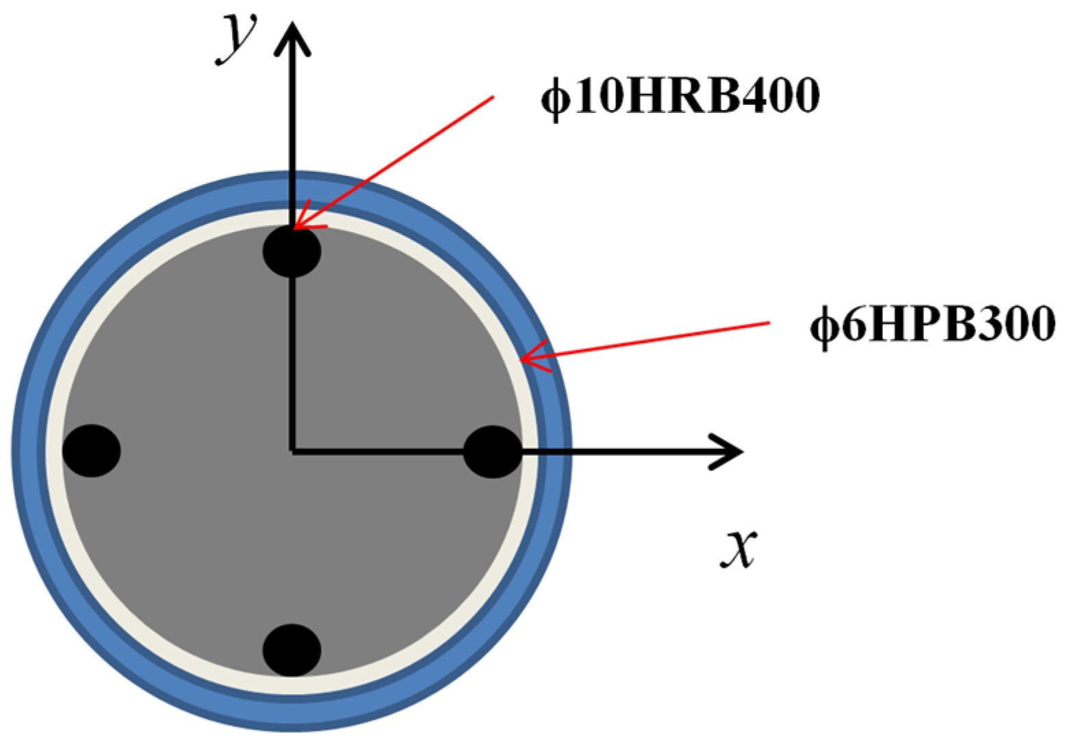
2.1. Specimen Design

The objective of this experiment was to investigate the behavior of CFRP-confined corroded reinforced concrete columns under axial compression, considering various rates of steel reinforcement corrosion, different numbers of CFRP wrapping layers, and various steel fiber contents. The specimens used in the study were cylindrical in shape, with dimensions of diameter D × height H of 150 mm × 300 mm. The reinforcement layout of the specimens is shown in Figure 1. A total of 4 specimens were made for this study, designated as C5-0, C5-1, C5-2, and C5-3. These designations correspond to the application of 0, 1, 2, and 3 layers of CFRP wrapping, respectively, at a steel corrosion rate of 5%.

2.2. Materials

This study utilized C40 strength grade concrete, with the selected materials including P.O 42.5 ordinary Portland cement, coarse aggregates with a two-level gradation consisting of sizes ranging from 5–10 mm and 10–20 mm, fine aggregates with a fineness modulus of 2.7 medium sand, as well as fly ash and silica fume. During preparation, the water-to-binder ratio was 0.48, with a two-level aggregate gradation, a fly ash replacement rate of 30%, and polycarboxylate as a superplasticizer high-efficiency water-reducing agent with a water reduction rate of 25% and a dosage of 0.1% of cement weight. The detailed concrete composition is shown in Table 1. The CFRP was produced by Carbon Fiber Technology Research Institute Co., Ltd. (in Nantong, China). The CFRP wrapping process is delineated as follows: (1) Trim the carbon fiber cloth to the requisite dimensions. (2) Conduct surface treatment of the concrete specimen and cleanse it with acetone. (3) Utilize a base adhesive to rectify any irregularities on the column surface, thereby ensuring optimal contact between the column and CFRP. (4) Prepare the carbon fiber cloth impregnation adhesive, which comprises two components, A and B adhesives, mixed in a ratio of 2:1. The mixed adhesive should be utilized within 25 min. The parameters are shown in Table 2. (5) Apply the impregnated adhesive uniformly to the CFRP encapsulation area and brush it on. The recommended adhesive usage is between 0.6–0.75 kg/m2. In the case of multi-layer wrapping, it is imperative to reiterate the previously described procedure subsequent to the solidification of the initial colloid layer. The overlapping regions of the multi-layer encapsulation must be uniformly distributed across the cross-sectional area. Detailed parameters are shown in Table 3. The longitudinal reinforcement is specified to be of ϕ10HRB400 grade, while the stirrups are designated as ϕ 6HPB300 grade (where ϕ stands for the diameter of steel bar in mm). The precise mix proportions for each set of specimens are provided in Table 1. Furthermore, in accordance with the test requirements, it is necessary to fabricate lightweight aggregate reinforced concrete specimens with varying steel fiber contents. To replicate the corrosion damage of reinforced concrete subjected to the saline conditions prevalent in the western region, an electrochemical accelerated corrosion method is utilized in this research. The corrosion rates are set at 5% and 10%, with corrosion periods of 15 days and 30 days, respectively. The corrosion will reduce the effective section area and the weight of steel reinforcement; therefore, the corrosion rate was obtained by measuring the weight change after corrosion. Upon completion of the corrosion process, the specimens are confined with CFRP, with options for 1, 2, or 3 layers of wrapping.

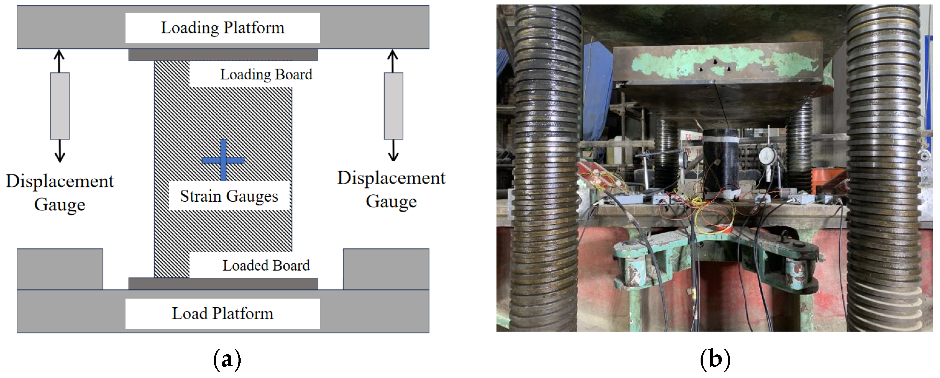
2.3. Loading Device and Protocol

All specimens were subjected to axial compression tests, and the experimental load was measured using a load sensor placed above the specimen. Before loading the specimens, their positions were first adjusted to ensure they were centered under the testing machine, followed by a pre-loading procedure. The purpose of pre-loading was to eliminate the influence of external factors during the loading process. During the formal loading of the specimens, load control was initially applied at a rate of 25 kN per minute. Upon reaching the peak load, the loading was switched to displacement control with an approximate displacement rate of 0.0025 mm per minute, continuing until the specimen failed. The specific configuration of the loading apparatus is shown in Figure 2.

3. Test Results and Analysis

3.1. Experimental Phenomena and Specimen Failure Modes

The failure mode of specimens with 5% steel reinforcement corrosion rate under axial compressive load is depicted in Figure 3a. The experimental observations primarily encompass the following: Initially, as the test commenced, the column progressively bore the applied load, resulting in axial compressive stress. As the load increased to 253 kN, the column’s deformation progressively amplified, entering a phase of linear growth. With a further increase in load to 433 kN, the central portion of the column exhibited a marked increase in deformation, accompanied by the emergence of multiple micro-cracks on the column’s surface. These cracks initiated from the aggregate surfaces and extended to adjacent aggregate surfaces. The appearance and propagation of these cracks led to a gradual reduction in the column’s stiffness, along with significant longitudinal deformation. As the cracks interconnected and the load reached 741 kN, the column approached the failure stage. The longitudinal steel reinforcement yielded and locally bent, forming multiple visible interconnected cracks at the surface, resulting in the spalling of the column’s surface and evident shear failure. The ultimate failure mode of the column was characterized by the yielding of the longitudinal steel reinforcement and the fragmentation of the concrete.
In summary, the experimental phenomena of reinforced concrete columns under axial compressive load primarily encompass three stages, which are as follows:
(a)
An elastic deformation stage characterized by a linear growth in the force–displacement curve.
(b)
The generation of micro-cracks in the concrete, known as the cracking stage.
(c)
As the cracks gradually connect, the spalling of the concrete surface occurs, along with the yielding and local bending of the longitudinal steel reinforcement, and the emergence of shear diagonal cracks, collectively constituting the failure stage.
The failure modes of CFRP-confined corroded reinforced concrete columns under axial compressive load are illustrated in Figure 3b–d. Initially, as the vertical load was applied, the force–displacement curves of all specimens exhibited a trend of linear growth, with no significant deformation or cracking observed throughout the process. As the load increased to 783 kN, specimen C-5-1 emitted a sound, but no evident lateral deformation was observed, indicating that the strengthening effect of the CFRP wrap had a certain restraining effect, inhibiting the generation of cracks and the spalling of concrete. The CFRP-confined corroded reinforced concrete columns exhibited a smaller degree of deformation and demonstrated good ductility and deformation capacity. Further loading to 1120 kN led specimen C5-1 to near its ultimate state, with the CFRP wrap on the column surface beginning to show signs of fracture. However, the overall structural performance remained relatively good, with no severe shear failure or crack propagation observed, which can be attributed to the reinforcing effect of the CFRP wrap effectively constraining the shear failure of the concrete. Specimens C5-2 and C5-3 approached their ultimate states at loads of 1197 kN and 1887 kN, respectively, with the difference in their load-bearing capacities due to the variation in the number of CFRP layers, highlighting the critical role of CFRP layering in enhancing the load-bearing capacity of the components. Apart from specimen C5-1, the specimens burst abruptly with a loud sound upon reaching the ultimate state, with the CFRP completely rupturing and the concrete surface shattering and falling off, leading to the failure of the specimens. Specimen LC5-1, with only one layer of CFRP wrap, had a weaker constraining effect on the column, resulting in a weaker sound upon failure and only local cracking of the CFRP, with the concrete surface peeling off only in the central section of the column. In summary, compared to columns without CFRP wrapping, CFRP-confined corroded reinforced concrete columns under axial compressive load exhibited smaller lateral expansion and deformation, fewer cracks, good ductility and deformation capacity, better maintenance of structural performance, and a comprehensive failure mode under extreme loading conditions. These phenomena underscore the significant role of CFRP wrapping in enhancing the compressive performance and ductility of columns.

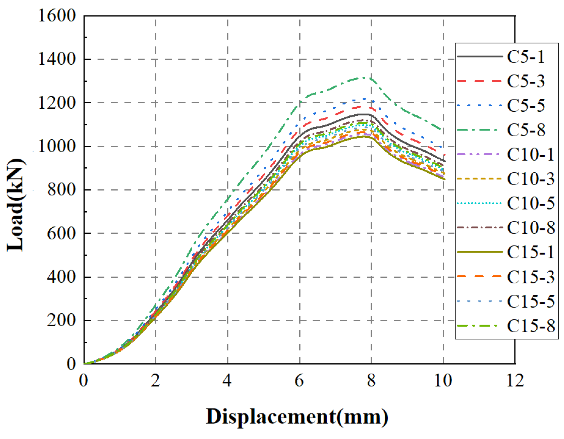
3.2. Load–Displacement Curve Analysis

Figure 4 presents the load–displacement curves for each specimen. It can be observed that the influence of the longitudinal steel reinforcement corrosion rate on the load–displacement curve is primarily evident in the initial stiffness stage. The corrosion of the longitudinal reinforcement makes the deformation of the column more prone to occur, resulting in a load–displacement curve with more nonlinear characteristics. As the number of CFRP layers increases, the load-bearing capacity of the column is significantly enhanced, and the trend of increasing displacement becomes relatively moderate, indicating an improvement in the ductility of the column. With the exception of specimen C5-0, the load–displacement curves for the specimens with CFRP confinement can be delineated into four principal stages: the elastic stage, the concrete cracking stage, the CFRP cracking stage, and the failure stage. In contrast, specimen C5-0 predominantly undergoes three stages: the elastic phase, the concrete cracking phase, and the failure phase. The specimens confined with CFRP demonstrate a notable enhancement in initial stiffness during the elastic phase and a significantly greater load-bearing capacity in the concrete cracking phase compared to the unreinforced specimens. In the CFRP cracking stage, the load-bearing capacity of the reinforced specimens exhibits a slower decline, indicative of the substantial constraining effect of CFRP on concrete cracking and lateral deformation. At the failure stage, the deformation of the CFRP-confined specimens is substantially greater than that of the non-reinforced specimens, highlighting the improved ductility resulting from CFRP confinement.
Furthermore, the comparison of specimens C5-1, C5-2, and C5-3 shows that, as a high-strength material, the additional CFRP layers effectively improve the overall stiffness and load-bearing capacity of the column. From the perspective of the load–displacement curves, the slope of the curve increases with the addition of CFRP layers, indicating a reduction in the deformation capacity of the column under load and an enhancement of the initial stiffness. Furthermore, the relatively moderate increase in the displacement rate suggests that the column can withstand greater deformation before reaching the peak load, demonstrating that CFRP wrapping not only increases the load-bearing capacity of the column, but also improves its ductility. This improvement is of great significance for enhancing the seismic performance of structures and extending their service life.

3.3. Feature Points Analysis

Table 4 presents the data for the characteristic points of each specimen. It can be observed that with the increase in the number of CFRP layers, the yield load capacity of the CFRP-confined reinforced concrete columns increased by 23%, 43.1%, and 126.8%, respectively, compared to the non-CFRP-confined columns, while the peak load capacity increased by 51.24%, 63.5%, and 159.3%. This indicates that the increase in the number of CFRP layers significantly enhances the load-bearing performance of the columns, leading to increases in both the peak load and yield load, as well as improving the deformation capacity of the columns. In practical engineering, it is advisable to increase the number of CFRP layers appropriately and determine the number of layers based on specific project requirements and conditions to ensure that the reinforced concrete columns exhibit good mechanical properties under axial compressive loads.
The external confinement of corroded reinforced concrete columns is primarily aimed at improving their brittleness, thereby preventing sudden failures of concrete columns that can lead to economic losses and casualties. Typically, ductility coefficients are used to quantify the extent of ductility of specimens. In this study, Equation (1) [21] is employed to calculate the ductility coefficient, with the displacement characteristic values of each specimen detailed in Table 5.
μ = x y
where x and y correspond to the displacement of the peak load and yield load of the specimen, respectively.
Under the corrosion rate of 5%, the number of CFRP layers has a more pronounced effect on the ductility of the specimens, with respective increases of 23.07%, 14.5%, and 13.9% in the ductility coefficient compared to specimen C5-0. This indicates that at a 5% corrosion rate, the strengthening effect of the CFRP cloth is more effective in compensating for this damage and enhancing the overall performance of the structure. Therefore, for reinforced concrete columns that have already undergone a certain degree of corrosion, increasing the number of CFRP layers can effectively increase the ductility coefficient and strengthen the mechanical properties of the column.

3.4. Strain Analysis

The stress–strain curves for reinforced concrete columns under axial compressive load at a 5% steel reinforcement corrosion rate and with different numbers of CFRP wrapping layers (0, 1, 2, 3) are presented in Figure 5. Initially, for columns wrapped with a single layer of CFRP, the stress–strain curve exhibits a relatively low rigidity in the initial stage, where stress is proportional to strain within a small range of strain. As the strain increases, the column progressively enters a nonlinear stage, showing greater deformation and a nonlinear stress–strain relationship. In columns wrapped with double layers of CFRP, the additional layers provide additional restraint and strengthening effects, resulting in a higher stiffness of the column. Therefore, in the initial elastic stage, the stress–strain curve has a greater slope and rigidity. Compared to a single layer of wrapping, the columns with double layers exhibit a steeper curve in the non-elastic stage, indicating greater deformation and load-bearing capacity. When the number of CFRP wrapping layers is increased to three, the characteristics of the stress–strain curve become more pronounced, with three layers providing stronger restraint and reinforcement effects, significantly increasing the overall stiffness of the column. Consequently, in both the elastic and non-elastic stages, the stress–strain curve is steeper with a greater slope.
In summary, the stress–strain curve characteristics of reinforced concrete columns under axial compressive load with different CFRP wrapping layer numbers share the following common features: an initial linear relationship, an increase in column stiffness with the addition of CFRP wrapping layers, and a steeper curve in the non-elastic stage, indicating greater deformation and load-bearing capacity.

4. Finite Element Analysis

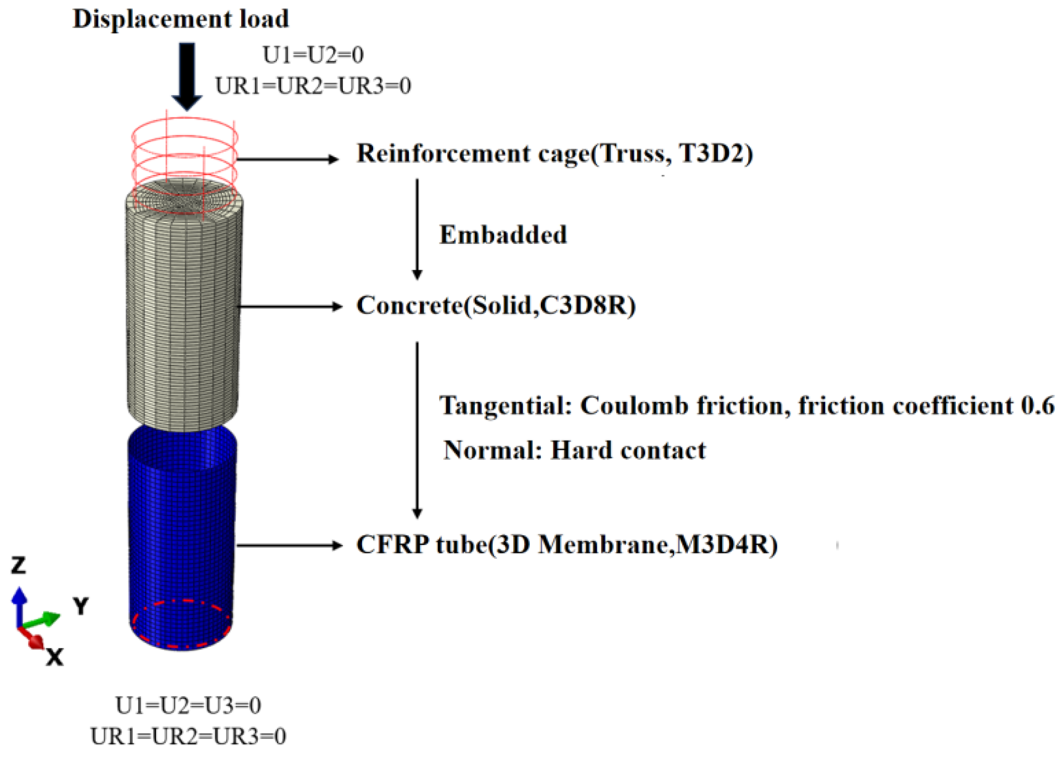
4.1. Finite Element Model Establishment

ABAQUS software was utilized to perform finite element analysis for this study. With the number of CFRP layers and the corrosion rate of steel bars as the change parameters, a total of 12 models were designed, and the specific parameters are shown in Table 6.

4.2. Constitutive Models

4.2.1. Constitutive Model of Steel

A previous study [22] conducted experimental research on the mechanical properties of corroded steel reinforcement through electrochemical corrosion tests. The results indicate that the yield strength, ultimate tensile strength, and elongation of the steel reinforcement decrease with increasing corrosion levels. When the steel corrosion rate is less than 10%, the reinforcement still maintains a distinct yield plateau. However, when the corrosion rate exceeds 20%, there is no longer a yield plateau. Given that the range of steel corrosion rates studied in this paper does not exceed 20%, the presence of a distinct yield plateau in the reinforcement is considered, and a five-segment line constitutive model is adopted. Additionally, according to the literature [23], when the stirrups are corroded, the cross-sectional area of the stirrups decreases, and the yield strength is reduced, leading to a decrease in the compressive strength of the core concrete constrained by the stirrups and the effective lateral restraint. Therefore, this study only considers the effect of corrosion on the steel yield strength. In calculating the yield strength of the steel reinforcement, the recommended values from the literature [23] are used, and the expression for the yield strength of corroded steel reinforcement is as follows:
f y s = f y 1 1.007 η s
where f y is the yield strength of non-corroded reinforcement, η s Is the degree of stirrup cross-section rust.

4.2.2. Constitutive Model of Concrete

In the model, the spiral stirrups, embedded within the concrete, provide a strong annular constraint on the core concrete, effectively inhibiting its transverse deformation. The combined action of the stirrups and longitudinal reinforcement places the core concrete under triaxial compression. Therefore, in the finite element simulation of this study, the concrete is characterized using the constitutive model for corroded steel-restrained concrete proposed in the literature [23]. This model is based on Mander’s general constraint concrete constitutive model [24], and it comprehensively analyzes the influence of corroded steel reinforcement on the stress–strain relationship of the core concrete, with the expression as follows:
f c = f c c x r r 1 + x r
ε c c = ε c o 1 + 5 f c c f c o 1
x = ε c ε c c
r = E c E c E sec
E c = 5000 f c o
E sec = f c c ε c c
where f c is the axial compressive stress of concrete, f c c is the peak stress of confined concrete, ε c is the axial strain of concrete, ε c c is the peak strain of confined concrete, E c is the elastic modulus of concrete, and E sec is the secant modulus of concrete.

4.2.3. Constitutive Model of CFRP

The failure of CFRP is typically caused by various fracture behaviors, including fiber breakage, matrix failure, interface delamination, and interlayer delamination. Carbon fibers exhibit extremely high strength and stiffness, and under tensile loading they can withstand significant strains while maintaining elasticity. However, it is precisely due to the high strength of the fibers that once the fibers reach their ultimate strain, their strength is insufficient to continue supporting the load, and they will suddenly fail through fiber breakage. The constitutive equation for CFRP cloth, representing this behavior, is as follows:
If   ε ε f ,   δ f = E ε f ,   ε > ε f , δ f = 0
When CFRP tubing is wrapped around a concrete column, it primarily serves to confine the concrete column. When the internal concrete exhibits Poisson’s effect, the CFRP tubing simultaneously bears the vertical axial compression and the hoop force of the concrete. As illustrated in Figure 6, the number of layers of the CFRP tubing and the direction of fiber stress are defined through the composite layer in ABAQUS. Here, n represents the fiber direction, 2 denotes the direction perpendicular to n, and Ref1 refers to the normal direction. The mechanical behavior during the elastic stage is simulated using the Lamina model, while the brittle fracture behavior at the ultimate load is modeled through the Hashin damage function. The material parameters for the CFRP tubing used in this study are detailed in Table 2.

4.2.4. Element Type, Meshing, and Contact Boundaries

Figure 7 illustrates the process of model establishment, indicating that after the model is set up and the interactions between different components are defined, the boundary conditions for simulating the T-shaped cross-section column need to be specified. To approximate real experimental loading conditions, the bottom of the simulated column is fixed in all directions, while the top end is fixed for rotation and displacement in the X, Y, and Z directions. Based on the finite element software ABAQUS, finite element mechanical performance analysis was conducted on 12 short column specimens. In the analysis model, concrete is represented by an eight-node hexahedral reduced integration solid element (C3D8R), CFRP cloth by a three-dimensional membrane element (M3D4R), and longitudinal reinforcing bars and stirrups by a three-dimensional two-node truss element (T3D2). The steel reinforcement cage is connected to the concrete using an embedded approach to achieve coordinated deformation between the steel and concrete. CFRP cloth is bonded to the concrete column, as depicted in Figure 7.

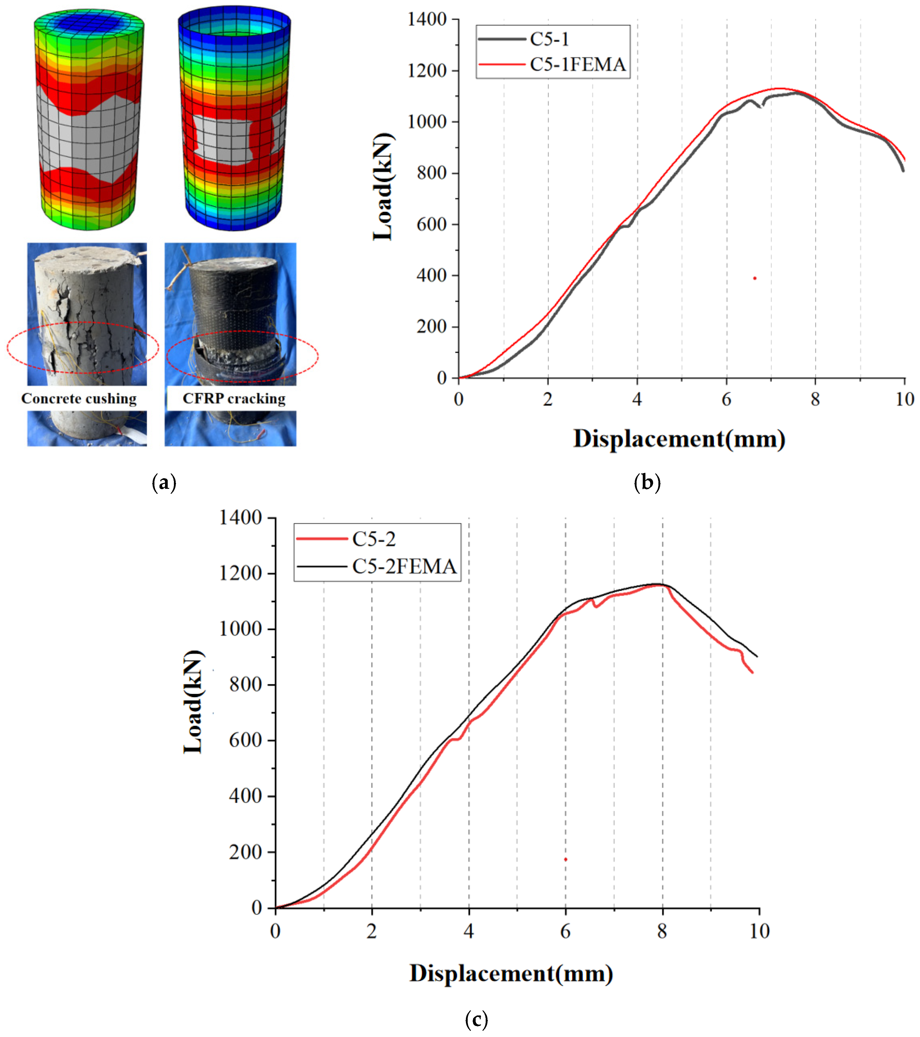
4.3. Verification of Finite Element Model

Figure 8a provides a comparison of the failure modes for a typical specimen, C5-1. From the experimental results, it is evident that concrete failure is primarily concentrated at the mid-section of the column at the ultimate state, with the CFRP cloth also showing damage at the mid-section. The modeling approach described above effectively simulates the phenomena of concrete crushing at the mid-section and CFRP cloth cracking at the mid-section under ultimate conditions. Figure 8b,c depict the load–displacement curves for all experimental specimens. It is observed that the initial stiffness obtained from the finite element modeling method presented here differs from the experimental values by a maximum of 5.6%, and the peak load capacity varies by a maximum of 4.7% compared to the experimental values. These results validate the accuracy of the finite element modeling method employed in this study.

4.4. Mechanism and Parameter Analysis

To further elucidate the working mechanism of CFRP-wrapped corroded reinforced concrete columns and to propose relevant construction recommendations, this section employs the aforementioned finite element modeling method to conduct a finite element analysis of a typical specimen, L-XX. By analyzing the entire process of member stress and contact stress, the failure mechanism and working mechanism of CFRP-wrapped corroded reinforced concrete columns are revealed. Based on this analysis, the impact of the number of CFRP wrapping layers under different corrosion rates on the mechanical properties of the components is assessed, and relevant recommendations for CFRP strengthening of corroded reinforced concrete columns are put forth.

4.4.1. Whole Stress Process Analysis

Taking specimen C5-1 as an example, a comprehensive analysis of its entire loading process is conducted, with the load–deformation curve of the component depicted in Figure 9. Based on the characteristics of the curve, the curve can be defined with four characteristic points. Initially, as the load is increased to 0.86mm, slight damage occurs near the loading end of the concrete cross-section, defining this moment as the concrete cracking point, or point A. The 0A segment is defined as the elastic working stage, where the component exhibits no significant damage or plastic deformation. Continuing the loading to 1.79 mm, the longitudinal reinforcement exhibits yielding, leading to a noticeable decrease in stiffness, defining this moment as the yield point of the reinforcement, or point B. The OB segment is thus defined as the yield stage of the longitudinal reinforcement. Further loading to 3.58 mm results in the maximum bearing capacity being reached, with the damage area in the concrete center expanding and the concrete being crushed, defining this moment as the concrete failure point, or point C. The BC segment represents the concrete failure stage. Finally, loading continues to 4.33 mm, where the CFRP at the mid-section shows significant damage, or point D, the CFRP cracking point. The CD segment represents the CFRP failure stage, characterized by a trend of initially decreasing and then increasing bearing capacity. During this stage, the CFRP provides a notable confinement effect, restricting the lateral deformation of the concrete after cracking, thus demonstrating the effectiveness of the wrapping action.
In summary, the entire loading process of the component can be defined as four stages: the elastic working stage, the yield stage of the longitudinal reinforcement, the concrete failure stage, and the CFRP failure stage.

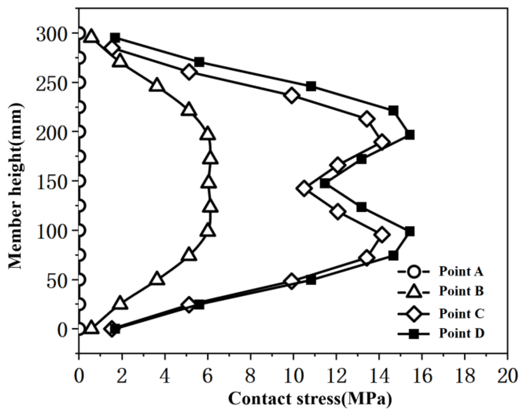
4.4.2. Contact Stress Analysis

Figure 10 presents the contact stress between concrete and CFRP. From the figure, it is evident that at characteristic point A, the contact stress between the concrete and the CFRP cloth is nearly zero, indicating that the CFRP did not exert any confinement on the concrete during the elastic working stage. At characteristic point B, when micro-cracks appear in the concrete and the reinforcement yields, the component experiences a certain hoop strain, and the confinement effect of the CFRP becomes evident. At characteristic point C, the number of connected cracks in the concrete increases, and the hoop strain of the component sharply increases. At this point, the confinement effect of the CFRP is more pronounced, with the contact stress increasing by 54.7% compared to characteristic point A. Further loading to characteristic point D shows an increase in the confinement effect of the CFRP by approximately 8.3% compared to characteristic point C.
These findings indicate that as the hoop strain of the concrete increases, the CFRP begins to exert a confinement effect, and the CFRP primarily plays a significant confinement role in the failure stage of the component.

4.4.3. Influence of CFRP Layer Number and Reinforcement Corrosion Rates

Figure 11 indicates that, with the same CFRP layer count of 1, as the steel corrosion rate increases, the yield load of the specimens decreases by 16.8%, 17.8%, and 19.3% compared to the model with a steel corrosion rate of 5%, suggesting that steel corrosion has a significant impact on the initial stiffness and peak bearing capacity of the column. Table 7 presents the feature point values and ductility coefficients for models affected by the steel corrosion rate. The table reveals that, under the same steel corrosion rate, as the number of CFRP layers increases, the yield load of the specimens improves by 20% to 65% compared to the one-layer CFRP, and the peak load increases by 21% to 71%.
In summary, it is evident that under the same steel corrosion rate, an increase in the number of CFRP layers results in a significant enhancement of the mechanical properties of the specimens. It is recommended that for a steel corrosion rate of 5%, the CFRP layer number should be 1 to 3, for a steel corrosion rate of 10%, the layer number should be 3 to 5, and for a steel corrosion rate of 15%, the layer number should be 6 to 8.

5. Formula of Bearing Capacity

Building upon the bearing capacity formula proposed by Lam et al. [25] for FRP-confined circular concrete columns, further derivation is conducted to develop a formula for the bearing capacity of FRP-confined concrete columns. It is noteworthy that the formula proposed by Lam et al. considers concrete compressive strengths less than 55 MPa. (The Lam formula was constructed through the analysis of comprehensive experimental data on CFRP reinforced concrete columns, with the concrete strength grades utilized in the experiments all being below 55 MPa. Consequently, the formula exhibits limitations with respect to concrete strength grades).
The calculation formula for the vertical bearing capacity of reinforced concrete short columns is as follows:
N = f c c A c + f y A s
where fcc is the strength of confined concrete, Ac is the sectional area of concrete, fy is the yield strength of steel, and As is the sum of the cross-section area of the steel reinforcement.
The strength of confined concrete can be calculated by the following formula:
f c c = f c ψ β 2 + γ β + 1 + k f l c + 4 f l s
where fc is the compressive strength of concrete, β is the steel fiber volume fraction, and ψ and γ are the fitting coefficients, taken as −6.1 and 34.2, respectively [26]. k is the stress coefficient of CFRP circumferential confinement, flc is the circumferential confinement stress of CFRP, and fls is the circumferential confinement stress provided by the stirrup.
The calculation methods of flc and fls are as follows:
f l c = 2 E n t ε r u p d
f l s = 2 f y A s s d c o r
where fy is the yield strength of the stirrup, As is the area of the stirrup, dcor is the core area diameter, s is the stirrup spacing, E is the tensile elastic modulus of CFRP, n is the number of CFRP layers, t is the CFRP thickness, εrup is the CFRP tear strain, and d is the diameter of column section.
For the corroded steel bar, the loss model of the circular concrete section is as follows:
A c = π r c 2
r c = r α c
where rc is the effective radius of the reinforced concrete short column after steel corrosion, Ac is the effective sectional area of the reinforced concrete short column after steel bar corrosion, r is the section radius of the concrete column, and αc is the geometric damage coefficient of the concrete protective layer in the compression zone of column section.
The yield strength of corroded reinforcement decreases linearly with the increase in corrosion rate. Wang [27] has established the relationship between the reduction factor of the yield strength of corroded reinforcement and the corrosion rate as follows:
γ s = 1 1.106 η s
where ηs is the actual corrosion rate of the steel reinforcement.
Combining Equations (9) to (15), the axial compressive bearing capacity calculation formula for confined corroded reinforced concrete columns is obtained:
N = π f c ψ β 2 + γ β + 1 + 2 k E n t ε r u p λ + 8 f y A s s d r α c 2 + f y A s 1 1.106 η s
The yield stress of longitudinal reinforcement is a critical parameter in the axial compressive bearing capacity calculation model. The axial compressive bearing capacity model developed in this study does not directly incorporate the peak stress of the longitudinal reinforcement, as it is commonly observed that the column does not experience a stress beyond the yield stress of the reinforcement when reaching its ultimate bearing capacity. Conversely, the peak stress model of longitudinal reinforcement is utilized to assess the stress distribution and failure behavior of the column at its maximum bearing capacity. Thus, the axial compressive bearing capacity calculation model and the peak stress model of longitudinal reinforcement are complementary in the design and study of reinforced concrete columns. They are used jointly to determine the bearing capacity of the column and evaluate its failure behavior, playing an indispensable role in the design process.
Figure 12 illustrates the comparison between the calculated results of Equation (16) and the experimental and simulated values. In the presented figure, the x-axis denotes the simulated and experimental values, while the y-axis represents the computed values as per Equation (16). The dashed lines on the graph delineate the ±5% and ±10% variance thresholds between the simulated and computed values. It is discernible from the figure that the discrepancy between the computed values from Equation (16) and the simulated and experimental values is predominantly within a 5% margin, signifying a high degree of concordance. The average prediction of the calculated values is 1.01, with a maximum error of 6.4% compared to the experimental results, indicating good accuracy.

6. Conclusions

This study conducted axial compression tests on four CFRP-confined corroded reinforced concrete short columns and compared the effects of different wrapping layer counts on the mechanical properties of the specimens. ABAQUS finite element software was employed to establish 12 models of CFRP-confined corroded reinforced concrete axial compressive short columns. The feature points of the entire stress process of typical components, as well as the contact stress between CFRP and reinforced concrete columns, were analyzed. Based on these analyses, a bearing capacity formula for CFRP-confined corroded reinforced concrete axial compressive short columns was proposed. The specific conclusions are as follows:
(1)
After CFRP confinement, the peak load of specimens with corroded reinforcement increased by 2.2 times. As the number of CFRP layers increased, the peak load of the specimens continued to rise, indicating that an increase in CFRP layer number significantly enhances the bearing capacity of reinforced concrete columns. After CFRP wrapping, the deformation capacity of the specimens decreased, and the bearing capacity increased significantly, with CFRP cloth failing in a bursting manner at the time of failure. The stress process of all specimens under axial compressive load can be divided into four parts: the linear elastic stage, the concrete cracking stage, the steel yielding stage, and the failure stage. As the hoop strain of the concrete increased, the CFRP began to exert a confinement effect, with the CFRP primarily playing a significant confinement role in the failure stage of the component.
(2)
The number of CFRP layers and the corrosion rate of longitudinal reinforcement had a significant impact on the ductility coefficient of reinforced concrete columns. Appropriately increasing the number of CFRP layers could effectively enhance the ductility coefficient of the columns, while an increase in the corrosion rate of longitudinal reinforcement led to a decrease in the ductility coefficient of the concrete columns. It is recommended that for a reinforcement corrosion rate of 5%, the CFRP layer number should be 1–3, for a corrosion rate of 10%, the layer number should be 3–5, and for a corrosion rate of 15%, the layer number should be 6–8.
(3)
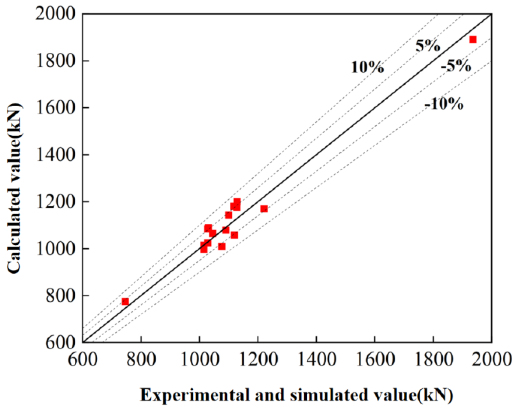
Based on experimental research and finite element analysis, combined with relevant research findings, this study proposed and validated a bearing capacity calculation formula for CFRP-confined concrete columns on the basis of the Lam formula. The maximum error between the calculated results of this formula and the finite element analysis results was 6.4%, indicating that the bearing capacity formula proposed in this study can accurately predict the behavior of CFRP-confined corroded reinforced concrete columns.

Author Contributions

Conceptualization, X.C.; Methodology, B.X. and Y.G.; Software, B.X. and H.L.; Validation, D.X.; Formal analysis, B.X. and Y.G.; Investigation, B.X., D.X. and X.Z.; Resources, X.C.; Data curation, X.C.; Writing—original draft, X.C.; Writing—review & editing, Y.G., H.L. and X.Z.; Visualization, Y.G., H.L. and D.X. All authors have read and agreed to the published version of the manuscript.

Funding

The research was funded by the Science and Technology Plan for Housing and Urban Rural Construction in Anhui Province (2022-YF018) and Anhui Province Key Laboratory of Green Building and Assembly Construction (2021-JKYL-003).

Data Availability Statement

The data presented in this study are available on request from the corresponding author due to privacy reason.

Conflicts of Interest

Author Yang Guo was employed by the company Anhui Construction Engineering Inspection Technology Group Co., Ltd. The remaining authors declare that the research was conducted in the absence of any commercial or financial relationships that could be construed as a potential conflict of interest.

References

  1. Chen, Z.P.; Xu, J.J.; Chen, Y.L.; Xue, J. Axial compression ratio limit values for steel reinforced concrete (SRC) special shaped columns. Steel Compos. Struct. 2016, 20, 295–316. [Google Scholar] [CrossRef]
  2. Qiao, Q.; Wu, H.; Cao, W.L.; Dong, H.; Zhang, J. Axial compressive behavior of special-shaped concrete filled tube mega column coupled with multiple cavities. Steel Compos. Struct. Int. J. 2017, 23, 633–646. [Google Scholar]
  3. Yang, Y.; Zhang, L.; Xue, Y.; Zhao, D.; Deng, H.; Wu, B. Experimental research on the fire performance of a special cross-shaped composite column with a high-strength concrete-filled steel tubular core. Adv. Struct. Eng. 2018, 21, 1608–1619. [Google Scholar] [CrossRef]
  4. Wang, X. The Mechanical Behavior Analysis of R.C Structure with Specially Shaped Columns and Related Components. Master’s Thesis, Taiyuan University of Technology, Taiyuan, China, 2011. [Google Scholar]
  5. Nugraha, A.D.; Nuryanta, M.I.; Sean, L.; Budiman, K.; Kusni, M.; Muflikhun, M.A. Recent progress on natural fibers mixed with CFRP and GFRP: Properties, characteristics, and failure behaviour. Polymers 2022, 14, 5138. [Google Scholar] [CrossRef] [PubMed]
  6. Xian, G.; Zhou, P.; Bai, Y.; Wang, J.; Li, C.; Dong, S.; Guo, R.; Li, J.; Du, H.; Zhong, J. Design, preparation and mechanical properties of novel glass fiber reinforced polypropylene bending bars. Constr. Build. Mater. 2024, 429, 136455. [Google Scholar] [CrossRef]
  7. Naser, M.Z.; Hawileh, R.A.; Abdalla, J.A. Fiber-reinforced polymer composites in strengthening reinforced concrete structures: A critical review. Eng. Struct. 2019, 198, 109542. [Google Scholar] [CrossRef]
  8. Kim, T.K.; Park, J.S.; Kim, S.H.; Jung, W.T. Structural behavior evaluation of reinforced concrete using the fiber-reinforced polymer strengthening method. Polymers 2021, 13, 780. [Google Scholar] [CrossRef] [PubMed]
  9. Singh, J.; Srivastawa, K.; Jana, S.; Dixit, C.; Ravichandran, S. Advancements in Lightweight Materials for Aerospace Structures: A Comprehensive Review. Acceleron Aerosp. J. 2024, 2, 173–183. [Google Scholar] [CrossRef]
  10. Zheng, H.; Zhang, W.; Li, B.; Zhu, J.; Wang, C.; Song, G.; Wu, G.; Yang, X.; Huang, Y.; Ma, L. Recent advances of interphases in carbon fiber-reinforced polymer composites: A review. Compos. Part B Eng. 2022, 233, 109639. [Google Scholar] [CrossRef]
  11. Gangineni, P.K.; Gupta, K.B.G.; Patnaik, S.; Prusty, R.K.; Ray, B.C. Recent advancements in interface engineering of carbon fiber reinforced polymer composites and their durability studies at different service temperatures. Polym. Compos. 2022, 43, 4126–4164. [Google Scholar] [CrossRef]
  12. Aidoo, J.; Harries, K.A.; Petrou, M.F. Fatigue behavior of carbon fiber reinforced polymer-strengthened reinforced concrete bridge girders. J. Compos. Constr. 2004, 8, 501–509. [Google Scholar] [CrossRef]
  13. Su, L.; Wang, Z.; Mai, Z.; Yang, S.; Liu, M.; Li, J.; Lu, Z.; Xie, J. Durability of corrosion-damaged RC beams strengthened with a small-diameter CFRP bar-reinforced geopolymer matrix system exposed to seawater. Constr. Build. Mater. 2024, 428, 136285. [Google Scholar] [CrossRef]
  14. Davis, S.; Martin, P. Design and Application Flexibility of Carbon Fiber Reinforced Polymer (CFRP) Composites in Civil Engineering. Eng. Struct. 2017, 150, 758–769. [Google Scholar]
  15. Zhu, Y.; Shao, Y. Finite element analysis of CFRP strengthened concrete composite torsional columns under monotonic loading. J. Suzhou Univ. Sci. Technol. (Eng. Technol. Ed.) 2023, 36, 17–22. (In Chinese) [Google Scholar]
  16. Kou, D. Numerical modelling study of Low-strength reinforced concrete columns reinforced by CFRP sheathing. Archit. Technol. 2023, 54, 1955–1959. (In Chinese) [Google Scholar]
  17. Gao, D.; Wang, T.; He, Y. Flexural test and calculation on capacity of reinforced concrete short beam strengthened by CFRP sheets. J. Build. Struct. 2017, 38, 122–131. (In Chinese) [Google Scholar]
  18. Xue, P. Experimental Study on Composite Reinforcement of Reinforced Concrete Axial Compression Members. Master’s Thesis, Huazhong University of Science and Technology, Wuhan, China, 2006. (In Chinese). [Google Scholar]
  19. Lu, Y.; Shi, J.; Zhao, G. Experimental research on concrete columns strengthened with the combination of CFRP and angle steel. J. Build. Struct. 2003, 24, 18–23. (In Chinese) [Google Scholar]
  20. Li, C.; Yu, A.; Gao, D.; Zhang, P. Experimental study on axial compression of corroded reinforced concrete columns strengthened with FRP strips under erosion environment. Acta Mater. Compos. Sin. 2020, 37, 2015–2028. (In Chinese) [Google Scholar]
  21. Liu, R.; Liang, J.; Wang, L. Axial compression performance of lithium slag concrete short column with CFRP round steel tube. J. Guangxi Univ. Sci. Technol. 2023, 34, 28–35. (In Chinese) [Google Scholar]
  22. Zhang, W.; Shang, D.; Gu, X. Stress-strain relationship of corroded steel bars. J. Tongji Univ. (Nat. Sci.) 2006, 34, 586–592. (In Chinese) [Google Scholar]
  23. Pan, L. Constitutive Relationship and Seismic Response Analysis of Corroded RC Circular Pier Columns. Master’s Thesis, Fuzhou University, Fuzhou, China, 2020. (In Chinese). [Google Scholar]
  24. Mander, J.A.B.; Priestley, M.J.N. Theoretical stress-strain model for confined concrete. J. Struct. Eng. 1988, 114, 1804–1826. [Google Scholar] [CrossRef]
  25. Lam, L.; Teng, J. Strength models for fiber-reinforced plastic-confined concrete. J. Struct. Eng. 2002, 128, 612–623. [Google Scholar] [CrossRef]
  26. Chen, X.; Xing, G.; Niu, J.; Liu, B. Behavior of plastic-steel fiber reinforced lightweight aggregate concrete columns subjected to concentric axial loading. Int. J. Civ. Eng. 2021, 19, 283–300. [Google Scholar] [CrossRef]
  27. Wang, J. Research on Axial Compression Performance of Corroded Reinforced Concreteshort Columns Strengthened by CC and CFRP. Master’s Thesis, Inner Mongolia University of Science and Technology, Baotou, China, 2022. (In Chinese). [Google Scholar]
Figure 1. Specimen section reinforcement layout.
Buildings 14 02412 g001
Figure 2. Loading device. (a) Loading device diagram; (b) Loading device in lab.
Buildings 14 02412 g002
Figure 3. Failure modes of CFRP-confined corroded reinforced concrete columns. (a) C5-0; (b) C5-1; (c) C5-2; (d) C5-3.
Buildings 14 02412 g003
Figure 4. Load–displacement curves under different corrosion rates.
Buildings 14 02412 g004
Figure 5. Stress-strain curves with different numbers of CFRP layers.
Buildings 14 02412 g005
Figure 6. CFRP tube composite layer definition.
Buildings 14 02412 g006
Figure 7. Modeling process.
Buildings 14 02412 g007
Figure 8. Verification of finite element model. (a) Failure mode comparison; (b) Load–displacement curve comparison of specimen C5-1; (c) Load–displacement curve comparison of specimen C5-2.
Buildings 14 02412 g008
Figure 9. Load–displacement curve of specimen C5-1.
Buildings 14 02412 g009
Figure 10. Contact stress between CFRP and concrete.
Buildings 14 02412 g010
Figure 11. Load–displacement curves.
Buildings 14 02412 g011
Figure 12. Calculation results of Equation (16).
Buildings 14 02412 g012
Table 1. Concrete composition (kg/m3).
GradeCementFly AshSilica FumeCoarse AggregatesMedium SandWaterWater-Reducing Agent
5~10 mm10~20 mm
C405001305032521654123313
Table 2. Parameters of carbon fiber impregnating adhesive.
Tensile Strength (MPa)Elastic Modulus (MPa)Elongation at Break (%)Compressive Strength (MPa)Bending Strength (MPa)Non-Volatile Matter
Content (%)
55.12.71 × 1032.4181.786.799.4
Table 3. Mechanical properties of CFRP.
TypeFilm Thickness
(mm)
Ultimate Tensile Strength (MPa)Elasticity
Modulus (GPa)
Ultimate Elongation (%)
CFS-I-3000.16735482331.62
Table 4. Feature point data.
Specimen No.Dy/mmDp/mmLy/kNLp/kN
C5-04.785.61635.74746.13
C5-15.598.05783.631128.48
C5-24.586.14910.001219.95
C5-36.018.071441.051934.98
Note: Dy is the yield displacement, Dp is the peak displacement, Ly is the yield load, Lp is the peak load.
Table 5. Ductility coefficient of each specimen.
Specimen No.xx/x0yμ
C5-05.611.004.781.17
C5-18.052.525.591.44
C5-26.142.734.581.34
C5-38.074.336.011.32
Table 6. Model parameters (mm).
No.Concrete GradeConcrete
Dimension
Reinforcement DimensionReinforcement Corrosion RateNumber of CFRP Layers
C5-1C40150 × 300HRB400/HRB30051
C5-3C40150 × 300HRB400/HRB30053
C5-5C40150 × 300HRB400/HRB30055
C5-8C40150 × 300HRB400/HRB30058
C10-1C40150 × 300HRB400/HRB300101
C10-3C40150 × 300HRB400/HRB300103
C10-5C40150 × 300HRB400/HRB300105
C10-8C40150 × 300HRB400/HRB300108
C15-1C40150 × 300HRB400/HRB300151
C15-3C40150 × 300HRB400/HRB300153
C15-5C40150 × 300HRB400/HRB300155
C15-8C40150 × 300HRB400/HRB300158
Table 7. Feature point data of each model.
Model No.Dy/mmLy/kNLp/kN
C5-14.73733.11027.25
C5-35.73796.111045.16
C5-55.84810.671119.25
C5-86.01842.891127.24
C10-14.55722.291014.42
C10-35.62781.351029.82
C10-55.75792.521089.47
C10-85.97809.821117.28
C15-14.42718.251014.44
C15-35.57765.871027.64
C15-55.62775.381075.25
C15-85.83789.231098.87
Note: Dy is the yield displacement, Ly is the yield load, Lp is the peak load.
Disclaimer/Publisher’s Note: The statements, opinions and data contained in all publications are solely those of the individual author(s) and contributor(s) and not of MDPI and/or the editor(s). MDPI and/or the editor(s) disclaim responsibility for any injury to people or property resulting from any ideas, methods, instructions or products referred to in the content.

