Article

Study of a Novel Updraft Tower Power Plant Combined with Wind and Solar Energy

1
School of Mechanical and Electrical Engineering, Xi’an University of Architecture and Technology, No. 13 Yanta Road, Xi‘an 710055, China
2
School of Information Engineering, Inner Mongolia University of Science and Technology, No. 7 Aerding Road, Baotou 014010, China
3
School of Chemical Engineering and Technology, Xi’an Jiaotong University, No. 28 Xianning West Road, Xi’an 710049, China
*
Author to whom correspondence should be addressed.
Buildings 2024, 14(8), 2416; https://doi.org/10.3390/buildings14082416
Submission received: 12 June 2024 / Revised: 23 July 2024 / Accepted: 4 August 2024 / Published: 5 August 2024
(This article belongs to the Section Building Energy, Physics, Environment, and Systems)

Abstract

:
This study presents a novel solar updraft tower power plant (SUTPP) system, which has been designed to achieve the simultaneous utilization of solar and wind energy resources in desert regions, in response to the pressing demand for sustainable and efficient renewable energy solutions. The aim of this research was to develop an integrated system that is capable of harnessing and converting these abundant energy sources into electrical power, thereby enhancing the renewable energy portfolio in arid environments. The methodology of this study involved the design and construction of a prototype SUTPP, comprising a 53 m high tower, a 6170 m2 collector, five horizontal-axis wind turbines, and a thermal energy storage layer made up of pebbles and sand. The experimental setup was meticulously detailed, and experiments were conducted to collect data on the system’s performance under various environmental conditions. Subsequently, three-dimensional numerical simulations were performed to explore the effects of ambient wind speed and solar radiation on the output power of the SUTPP. The results indicate that the output power of the system increases with the increase in ambient wind speed and solar radiation. The impact of solar irradiation on output power was observed to diminish as ambient wind speeds increased. Notably, as the inlet wind speed rose from 4 m/s to 12 m/s, the output power showed a substantial increase of 727%. The numerical simulations revealed that ambient wind speed has a more pronounced effect on power output compared to solar radiation. Furthermore, it was found that the influence of solar radiation is significant at low wind speeds, with its impact decreasing as wind speed increases. This research provides essential guidance for the design and engineering of highly efficient solar thermal energy utilization projects, representing a significant advancement in the field of renewable energy technology deployment in desert environments.

1. Introduction

Among the renewable energy sources, solar energy has received considerable attention in the field of engineering sciences and is regarded as a promising option in industries [1]. At present, solar energy conversion is widely used to generate heat and produce electricity [2,3]. Large-scale solar thermal systems with large stationary collector fields are the most economically viable [4]. One of the most promising of these technologies is the solar updraft tower power plant (SUTPP) [5]. A conventional SUTPP consists of a circular collector with a circular tower located at its center and one or more turbines located at the tower base as power conversion units. Solar irradiation penetrates the collector roof and strikes the surface ground. The heated ground heats the adjacent air resulting in a temperature difference between the air inside and outside the system. The inside air warms, expands, and streams toward the tower’s elevated center. The kinetic energy of the airflow will be partly transformed into electric power, and the remaining kinetic energy and the thermal energy of the warm air current are mainly converted to gravitational potential energy under the effects of the initial momentum and the buoyancy force. The majority of the cost associated with solar updraft towers is the initial investment required, and they have low maintenance costs and high reliability. Additionally, the SUTPPs generate power without noise pollution and without emitting exhaust gases. This is a significant advantage over traditional fossil fuel-based power plants, which can contribute to air pollution and noise pollution. The clean operation of SUTPPs aligns well with the global push toward more sustainable and environmentally friendly energy sources [6].
The goal of the SUTPP is to produce large-scale electricity from solar power, which requires a massive land resource. The most appropriate construction locations for solar chimney power plants are in vast desert areas, where the land costs are cheap [7]. A desert area has generally abundant solar energy and large-scale land resources and is thereby suitable for an SUTPP [8]. Zhou et al. [9] developed a thermal model of a commercial SCPP proposed in a desert in western China, and they concluded that the most suitable construction sites for large-scale SCPPs are vast desert regions, where land may be cheap or free because of the large land area requirement. In the study of Al-Kayiem and Aja [10], they pointed out that the applicability of using SCPPs in solving the energy need in rural areas has been investigated and was found suitable for power generation in remote areas, which will help solve the energy problem in less developed countries.
The SUTPP technology can be traced back to the early 1980s; Haaf et al. [11] reported that the first SUTTP was built with a designed peak output of 50 kW in Manzanares. This pilot plant was in operation from 1982 to 1989 [12]. Based on the Spanish prototype system, Schlaich et al. [13] conducted fundamental investigations on the SUTTP and discussed the energy balance, design criteria, and cost analysis. At the same time, relevant numerical simulation work has also been carried out to study the working principle and optimization of SUTPPs, and conclusions were drawn regarding the SUTPP performance [14,15]. By adopting a new convective heat transfer equation, Pretorius and Kröger [16] investigated that the new model showed a more realistic turbine inlet loss coefficient and a better quality collector roof glass. They pointed out that the effect of a more accurate turbine inlet loss coefficient was insignificant while utilizing better quality glass and enhancing the plant power production. Zhou et al. [17] developed a mathematical model to evaluate the performance of the SUTTP built in the Qinghai-Tibet Plateau. They found that SUTTPs built in the Qinghai-Tibet Plateau can produce twice the power than those built in other regions at the same latitude.
The overall efficiency of the system depends on the proper design of the solar collector, the tower [18], and the turbine [19,20]. In the study of Torabi et al. [21], they concluded that the radius of the solar chimney and solar radiation have a direct relation with power generation. For the optimization of solar collectors, research has focused on the collector area, slope, optical properties, material, and inlet design [22,23]. Cuce et al. [24] investigated the collector slope and chimney slope on the power output for the Manzanares pilot plant with a 3D CFD model. They pointed out that the system provided maximum power at a 0.6° collector slope and a 1.5° chimney divergence angle. Rezaei et al. [25] experimentally developed a novel collector with metallic tubes as solar radiation absorbers hung from the canopy of the collector to improve the system efficiency. They found that the temperature increased by about 5 K at the chimney inlet, which leads to a roughly 8% rise in collector efficiency due to the fact that metallic tubes operate as an extended surface. Singh et al. [26] conducted a comparison between the divergent chimney and the conventional chimney. Results show that the optimum divergent chimney can reduce the vertical limit by about 80% of the height of a conventional cylindrical chimney.
For the optimization of the chimney structure, Eryener [27] introduced the prototype of SUTPP with a 300 m2 solar collector, 18.5 m high diffuser-shaped prismatic 2 downdraft with windcatchers updraft towers, and two vertical axis turbines. The annual energy output of downdraft wind catcher integration was eight times that of the traditional solar updraft tower. The results reveal that the downdraft tower integration had remarkable potential for extensive use in solar updraft towers. Moreover, the optimization of the fillet size at the base of the chimney of an SUTPP was conducted by Vivek and Chandramohan [28]; the results showed that a fillet size of 2.5 m showed a 61% increment in air velocity, which in turn led to a 97% increment in power and 96.5% on overall efficiency. Das and Chandramohan [29] developed a computation model to investigate the effect of the chimney height on the flow characteristics, and the results show that the velocity was enhanced by up to 44% as the chimney height increased from 3 to 8 m. In the study of Das and Chandramohan [30], they concluded that the air velocity, pressure gradient, volume flow rate, power output, and turbine efficiency were maximized at a chimney divergent angle of 2°. Since the turbine is the key component of the SUTTP, to substantiate which turbine is the most suitable, Esmail et al. [31] investigated the so-called matrix through-flow method, the classic blade element theory (BET), and a modification of the BET-based design. The results show that the modified BET-based design provides the highest output power, compared to the two other designs. Xue and Esmaeilpour [32] proposed Curved-Guide Vanes (CGVs) for the SUTTP and investigated the influence of the CGV’s angle on the flow field and maximum output power. It was found that the maximum power output of 82.174 kW was obtained at 80 rpm by the 30° guide. Balijepalli et al. [33] estimated and optimized the pitch angle, relative wind angle, lift force, and relative chord length of the rotor blade by using the Schmitz theory and the theory of aerodynamic forces on an airfoil. The result showed that the pitch angle, relative wind angle, and lift force were optimized at 18.4°, 26.4°, and 0.0052 N, respectively.
Moreover, it is commonly acknowledged that the efficacy of SUTPPs is primarily influenced by environmental factors such as solar radiation intensity, wind speed, and ambient air temperature. Consequently, numerous experimental and numerical investigations have been undertaken to explore the impact of ambient temperature and solar radiation on the rise in collector temperature and the updraft velocity of air within the chimney tower. It is a widely accepted conclusion that an increase in solar radiation intensity and ambient air temperature significantly boosts the airflow velocity within the SUTPPs [34,35]. Moreover, few studies have highlighted the effect of ambient wind speed on SUTPP performance [36,37]. The output power of traditional SUTPPs mainly depends on intense solar radiation, which leads to low efficiency during the night and on rainy days [38]. To improve efficiency, wind power may be utilized as a supplemental energy source. However, based on our knowledge, a study to integrate wind power with SUTPPs is not available, and such a combination of systems needs to be evaluated.
The desert region has sufficient and omnipresent wind power, which is freely available and environmentally friendly. Therefore, based on the SUTPP, this study attempted to extract solar and wind energy synchronously during solar radiation during the daytime and solely utilized wind energy when sunlight was absent. In this study, we introduce a novel approach to enhance the efficiency and reliability of SUTPPs by integrating wind power as a supplemental energy source. Currently, there is a significant gap in the literature regarding the integration of wind energy with SUTPP systems, particularly in desert regions, where both solar and wind resources are abundant yet underutilized in combination. Our research addresses this gap by exploring the simultaneous extraction of solar and wind energy during daylight hours as well as the exclusive use of wind energy during periods of solar radiation absence. In this study, the structure of the novel SUTPP was introduced. The experimental results were discussed, and the effects of the ambient wind velocity and solar radiation on the output power of the novel SUTPP were analyzed. To investigate the influence of the ambient wind speed and solar radiation on the temperature rise, air velocity, and output power of the novel SUTPP, we performed numerical simulations based on the constructed novel SUTPP. This study provides insights into the combination of wind and solar energy utilized in the SUTPP in the desert region as well as suggestions for the uninterrupted power supply of SUTPPs based on solar and wind energy.

2. Experimental System and Model Development

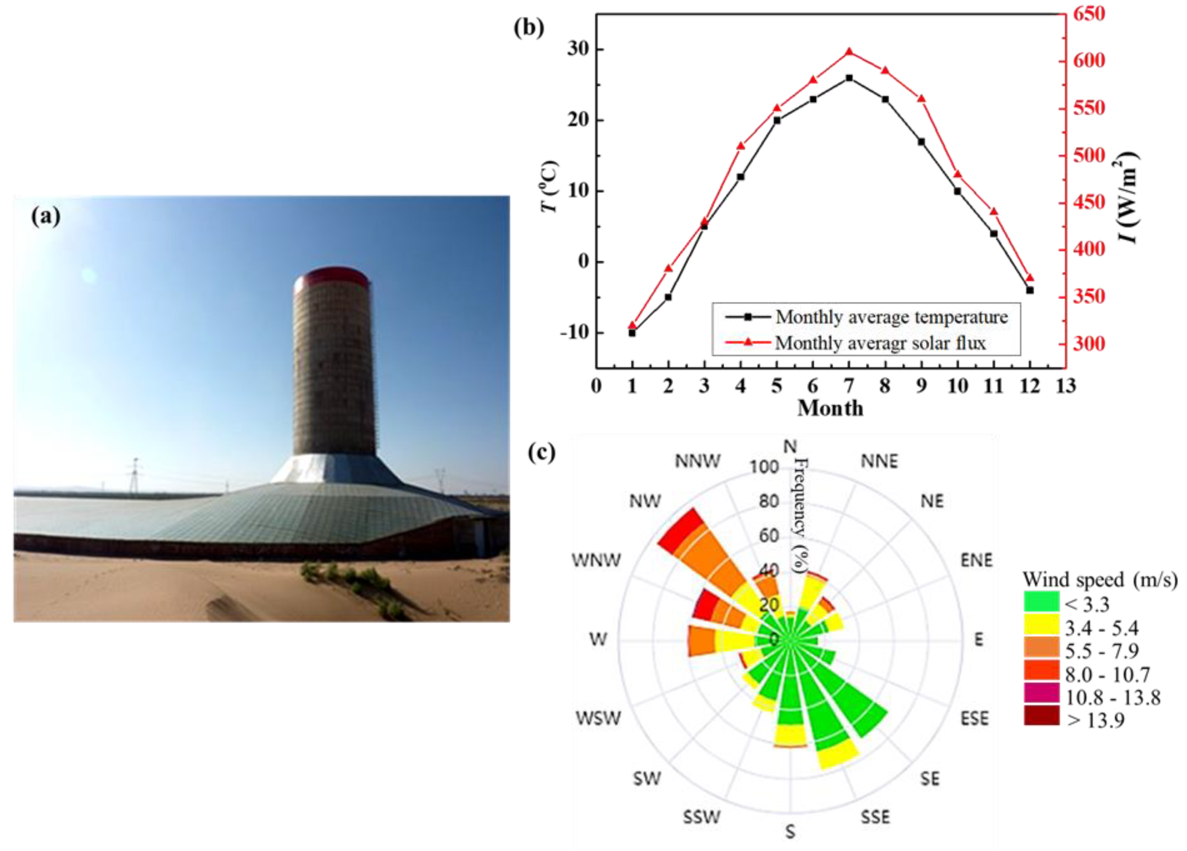
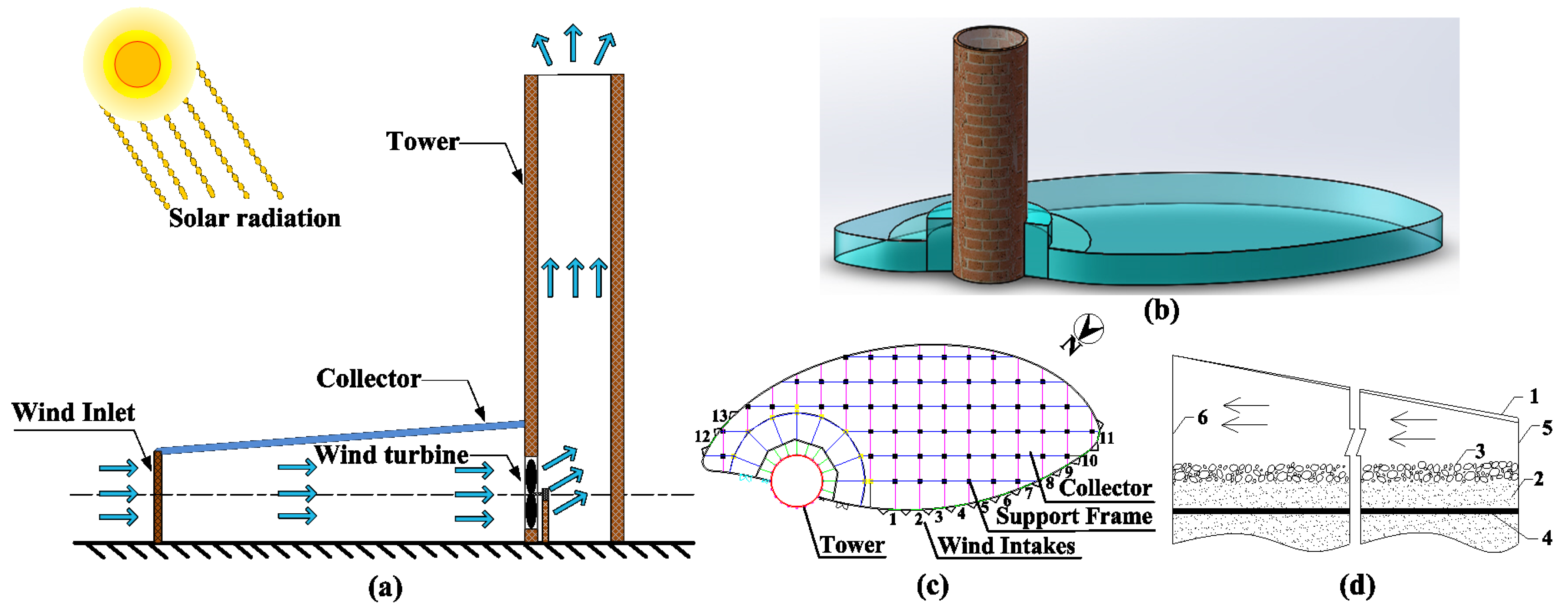
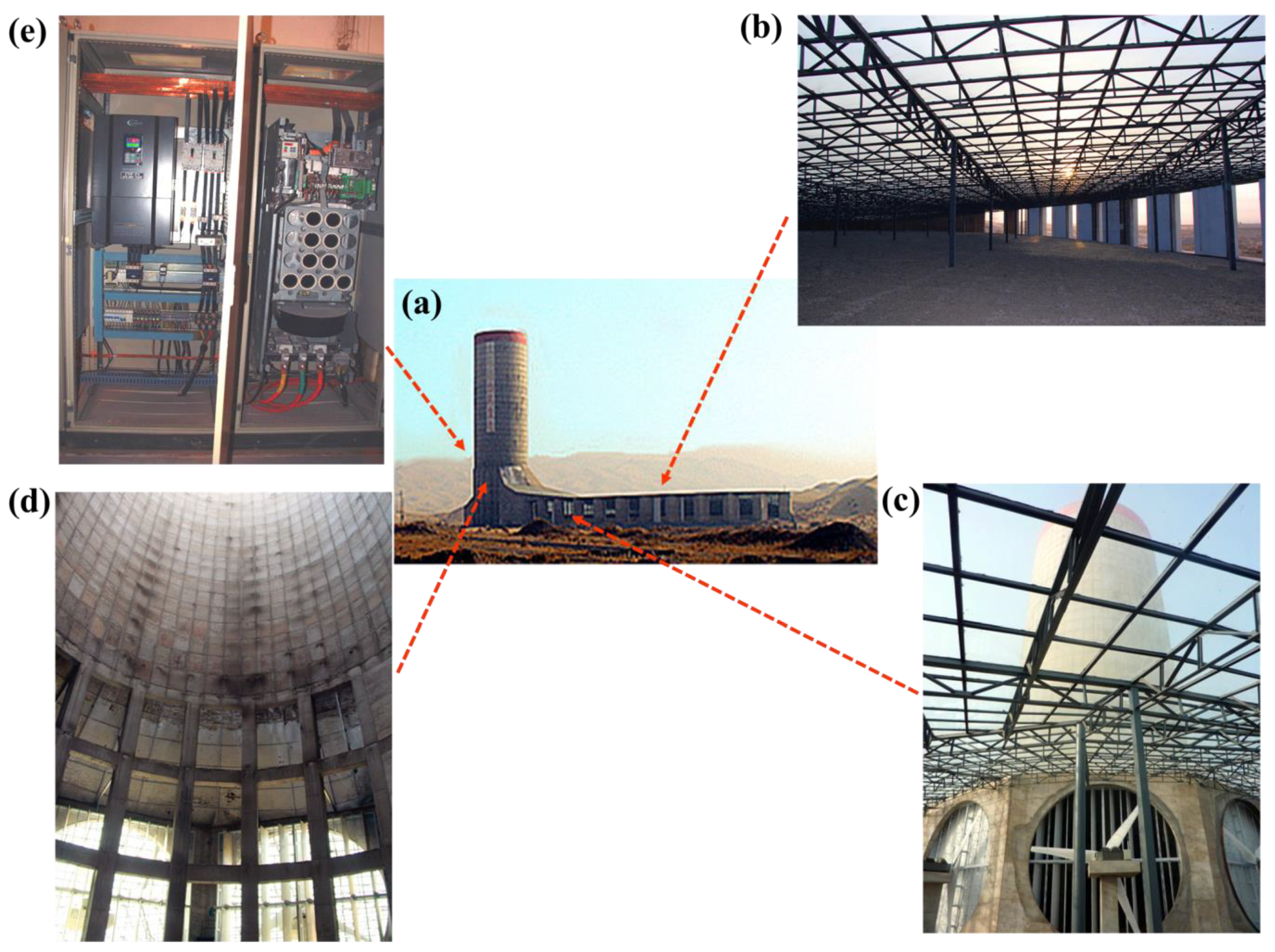
2.1. Experimental System

To design an SUTPP at a particular geographical location, the dimensions and shape of the collector roof and tower must be optimized to maximize the power output and minimize the construction cost. Therefore, considering the local natural environment conditions and cost, our research group designed a novel SUTPP in the Jinsha Desert, Wuhai City, Inner Mongolia, China. Wuhai has abundant solar resources, with an annual sunshine duration of 3000–3200 h. The photo of the SUTPP and meteorological conditions in Wuhai are shown in Figure 1a. At the prototype site, as shown in Figure 1b, the annual average solar irradiation is approximately 500 W/m2, and the maximum solar irradiation could reach 1000 W/m2 in summer. The annual average temperature is around 10 °C. The prevailing northwesterly winds have an annual average speed and maximum wind speed of 2.9 and 33 m/s (Figure 1c), respectively. Therefore, the geographical environment is highly favorable for the utilization of solar and wind energy.
The three-dimensional (3D) diagram of the experimental apparatus is shown in Figure 2a,b. As shown in Figure 2c, the collector adopted an approximately semi-circular shape. The novel structure of this SUTPP is designed based on previous studies of our group [39,40]. Designs for maximum energy capture from wind were considered based on the direction of the local prevailing wind. Eleven controllable air inlets were installed along the north-western rim of the solar collector facing the predominant wind direction. The solar tower was constructed at the north-northeast rim. Moreover, the other two inlets were placed toward the northeastern direction to protect the system from overloading and to optimize the utilization of wind energy during wind changes. The opening of the air inlets can be regulated through sensors and controllers based on the wind speed and direction for optimal performance. The energy storage element within the solar collector is a critical component of our system, designed to harness and store the thermal energy derived from solar radiation. As shown in Figure 2d, because the power plant was built in the Jinsha Desert, the local desert resources have been innovatively utilized, employing pebbles and desert sand as energy storage materials due to their cost-effectiveness and availability. The sand absorbs thermal energy from the sun and slowly releases it, which can be used to increase air temperature and drive the updraft even when direct solar radiation is not available [41,42,43]. The layer of pebbles contributes to the thermal mass of the collector. The pebbles store heat during the day and release it gradually, helping to maintain a consistent temperature within the collector. The pebble layer also functions to stabilize the desert sand, preventing it from shifting and ensuring optimal energy storage performance. Furthermore, recognizing that the deep desert sand contains moisture, which could lead to reduced surface temperatures and diminished solar energy utilization due to evaporative cooling, a waterproof layer was incorporated beneath the energy storage medium. This layer minimizes evaporation, thereby enhancing the thermal efficiency of the system.
The experimental system, as depicted in Figure 3a, featured a tower with a height of 53 m and a diameter of 18.5 m. The collector area, which was 6170 m2, was strategically designed to optimize solar energy capture. The tower was equipped with five entrances, each with a diameter of 8.2 m, ensuring efficient airflow. Both the collector area and the tower were meticulously sealed to maintain the integrity of the system. The collector roof was made of tempered glass and supported by a steel framework, as shown in Figure 3b,c. The collector tilt matched the solar resource feature. The toughened glass roof, which uses the greenhouse effect, was able to effectively stop long-wave heat radiation upwardly emitted by the heat storage medium. The internal structure of the tower is shown in Figure 3d. The cylindrical solar tower was made of cement, steel, and bricks, and the basement employed the three reverse casting methods. The tower required a relatively thin, reinforced ring-shell wall and was reinforced with stiffening rings. As shown in Figure 3c,d, five horizontal-axis wind turbines with three blades were installed at the bottom zone of the tower. The length of one blade was 4 m, and the rated power of each unit was 40 kW. Squirrel cage induction motors, which had simple structures, flexible adjustment, high efficiency, and no hysteresis, were employed as generators in the wind turbine system. Figure 3e shows one inverter (CONVO-CVF-P3-4T04450, Bosch Rexroth AG & Co. KG, Shenzhen, China) unit of the prototype. The simplified firmware of the control system is shown in Figure 4. The S7-300 PLC (Siemens AG, Munich, Germany) was adopted as the main controller. It collected and processed field sensor signals and the controller’s output signals and then relayed orders to field actuators via the Profibus control network. The PLC and inverter controllers controlled the rotor speed and the yaw angle error according to the wind speed and direction measured by wind anemometers and vanes to approximately track wind speed fluctuations. This controlling method was employed to improve efficiency in converting wind energy to electrical energy and is widely used in wind energy applications [44,45]. Moreover, remote-control technology was used in this control system, which enables us to monitor and control the operation of the plant from the laboratory through the Internet. During the experiment, the power generated by the wind turbine was recorded.

2.2. Model Development

2.2.1. Model Assumptions

In this study, the experimental section is dedicated to introducing and assessing the novel SUTPP prototype, capturing its performance under diverse environmental conditions, especially the effect of solar radiation on power output. The numerical simulations are essential, complementing the empirical data by providing detailed analysis of critical parameters such as the temperature rise and air velocity at the turbine inlet. Moreover, the numerical work is crucial for validating and refining our computational models. The integration of experimental and numerical analyses is vital for a comprehensive understanding of the SUTPP’s operational dynamics, allowing for the optimization of system design and performance. Therefore, in this study, a 3D numerical model was set up to evaluate the influence of two dominant factors, namely, the ambient wind speed and solar irradiation. Simulations were carried out with the commercial CFD software Fluent 6.3.26. In the simulation, the geometry parameters of the real prototype were adopted. However, many negligible details were not considered to reduce calculation time. Moreover, the following assumptions were made to simplify the simulation.
(1)
The airflow inside the collector and the tower can be regarded as an incompressible flow, and the Boussinesq hypothesis is applicable to this system.
(2)
The non-uniform heating of the collector surface in terms of the solar altitude angle is neglected.
(3)
The energy storage layer is not included in the SUTPP system because it can be neglected in the steady-state simulation.
(4)
Radiation models are not used because the radiation heat transfer inside the collector and tower is small compared with the conduction and convection.
(5)
The collector efficiency is not considered.

2.2.2. Governing Equations

The natural convection in the tower is caused by the buoyancy from the heated air. The Rayleigh number evaluates the strength of this buoyancy-induced flow.
R a = g β Δ T L 3 ρ μ α
where g is the gravitational acceleration, β is the thermal expansion coefficient of air, Δ T is the maximum temperature difference in the solar tower, L is the height of the collector, and μ and α are the kinetic viscosity and the thermal diffusivity of air, respectively. In general, when Ra reaches 108, the flow transforms from laminar to turbulent [46,47]. According to experimental data, the Ra in this SUTPP system is estimated from 2.2 × 10¹² to 4.5 × 10¹⁴; thus, the flow is turbulent. An RNG κ-ε two-equation model is utilized to simulate the turbulent flow.
The mathematical model of the SC system includes continuous equations, momentum equations, energy equations, and κ-ε equations based on the following 3D assumptions in tensor form:
( ρ u j ) x j = 0
( ρ u i u j ) x j = p x j + x j [ ( μ + μ l ) ( u i x j + u j x i 2 3 u k x k δ i j ) ] + ρ g i
( ρ u j c p T ) x j = x j [ ( λ + μ t c p σ T ) T x j ] + u i x j [ ( μ + μ l ) ( u i x j + u j x i 2 3 u k x k δ i j ) ] + μ j p x j
( ρ u j κ ) x j = x j [ α κ ( μ + μ t ) κ x j ] + G κ + G b ρ ε Y M
( ρ u j ε ) x j = x j [ α ε ( μ + μ t ) ε x j ] + C 1 ε ε κ ( G k + C 3 ε ) C 2 ε ρ ε 2 κ
where Gκ represents the turbulence kinetic energy due to velocity gradient, Gb represents the turbulence kinetic energy due to buoyancy, YM represents the dissipation rate due to fluctuating expansion, ε represents the turbulent dissipation rate, C 1 ε = 1.44, and C 2 ε = 1.92.
According to the Betz power limit [48], the pressure jump at the turbine can be calculated as follows:
Δ p t = 8 ρ t U t 2 27
where ρ t represents the average air density at the turbine section and Ut represents the average air velocity at the turbine section. The output power through the turbine can be calculated as follows:
W t = η t Δ p t V
where η t represents the efficiency of the turbine, which can be set as 0.8 [30], and V represents the volume flow rate at the turbine section.

2.2.3. Boundary Conditions

The boundary conditions were as follows. The ambient temperature of 293.15 K was selected because it is the typical value from April to October. The convection between the collector roof and inner air was considered, and the coefficient of convection was set as 20 W/m2 K. The inlet of the collector was set as the pressure-inlet boundary, the tower wall was set as an adiabatic boundary, and the tower outlet was set as the pressure-outlet boundary. Both inlet and outlet pressures were set to atmospheric pressure (1 atm). Solar radiation was regarded as a constant heat flux fixed on the collector bottom (energy storage layer).
In this study, we considered the influence of ambient wind speed outside the collector. To simplify the simulation, we regarded the influence of the ambient wind as an extra static pressure fixed on the inlet of the collector. Thus, the wind speed was transformed to a static pressure expressed as follows:
P i n l e t = ρ v a m b 2 2
where v a m b represents the ambient wind speed outside the tower. The boundary conditions at different sections are shown in Table 1.

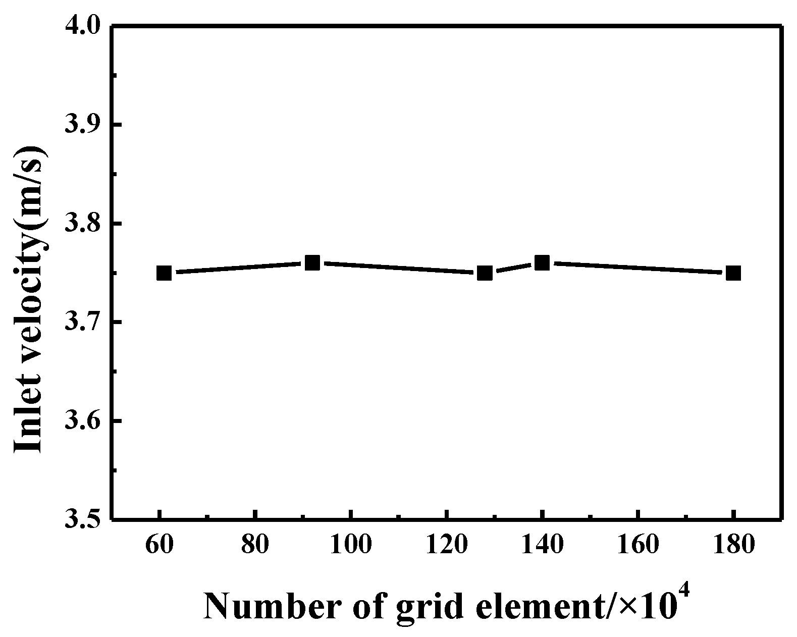
2.2.4. Solution Method

In the simulation, the Boussinesq approach was used to define air density. The SIMPLE algorithm was employed to couple the pressure and velocity, and equations, such as momentum and energy equations, were discretized with a second-order upwind scheme. The PRESTO method was utilized to calculate the pressure values on the volume surface. The mesh number of the SUTPP model was approximately 1,200,000. These cells were used after the grid-independent test (Figure 5). The number of grids varied from 600,000 to 1,800,000, but the inlet velocity change was inconspicuous.

3. Results and Discussion

In the experimental investigation, the data collected from the practical novel prototype built in the Jinsha Desert were analyzed. The developed SUTPP is engineered to capture the dual benefits of solar and wind energy. By analyzing the ambient wind speed and solar irradiation, the synergistic effects of these renewable resources on the system’s overall performance are discussed. The selection of the ambient wind speed and solar irradiation for analysis is rooted in their pivotal role in dictating the SUTPP’s performance. The ambient wind speed and solar irradiation are identified as keystones of the SUTPP’s energy conversion mechanism, exerting a direct influence on the dynamics of buoyancy-driven airflow and the thermal energy harnessed for electrical conversion. Therefore, the effects of the two main factors, namely, the ambient wind speed and solar radiation, are discussed. The numerical simulation provided insights into the coupling effects of the ambient wind speed and solar radiation on the temperature rise, air velocity, and output power.

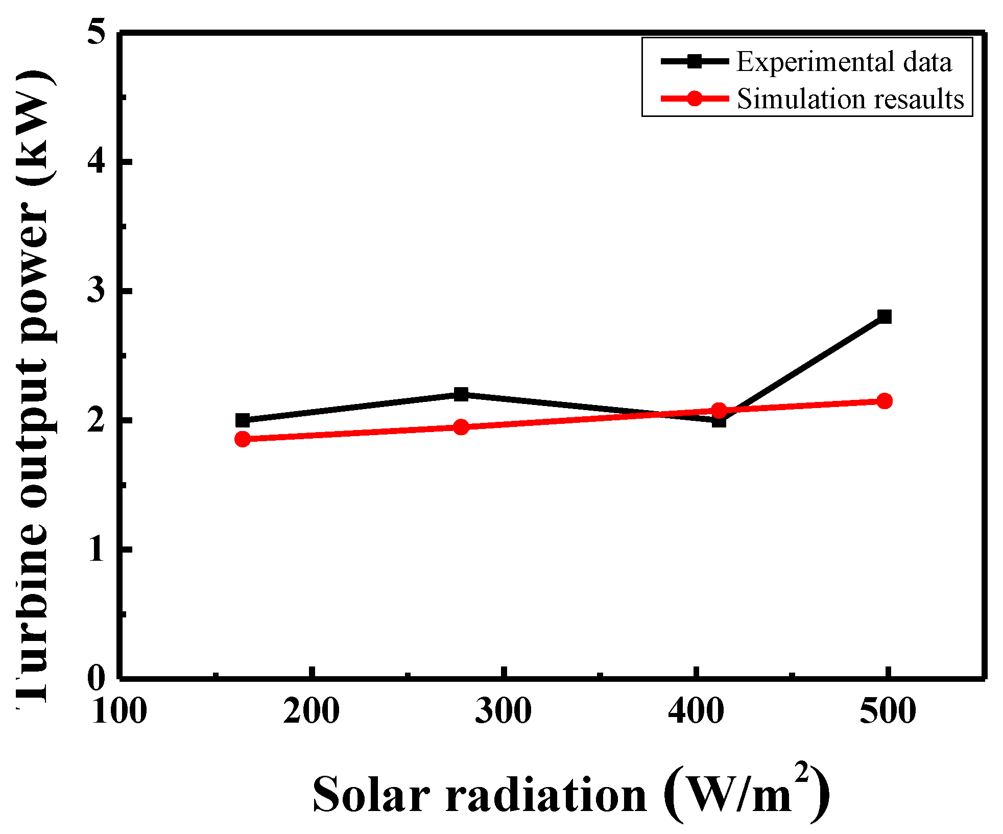
3.1. Model Validation

Validation of the numerical model was carried out by comparing the experimental data and the simulation results. Four experiment points were chosen to validate our numerical method. The experimental data were measured at an ambient speed of approximately 5.5 m/s and at a solar radiation range of 164 W/m2 to 498 W/m2. As shown in Figure 6, the average difference between the experimental data and the simulation results is 11.9%. The differences may be caused by the simplification of the mathematical model, as many influential factors, such as the number of open intakes, the intake’s opening direction, the humidity, sand and dust in the air, and cloud cover, were not considered in our numerical simulation. Moreover, the characteristics of wind power and solar power, such as volatility and randomness, may result in operational and reliability problems. Therefore, considering the simplifications in numerical simulation and randomness in the experiment, the difference between the experimental data and the simulation results is reasonable, and the simulation method in this paper is effective.

3.2. Experimental Results

3.2.1. Effects of Solar Radiation

The effects of solar radiation on the output power were studied. Figure 7 depicts the variation in output power with regard to different solar radiations, and the experimental data were measured at an approximate ambient wind speed of 5.5 m/s. vamb represents the ambient wind speed. The result clearly shows that the output power increased with increasing solar radiation. This observation is pivotal as it demonstrates the system’s sensitivity to solar energy, a critical factor for optimizing the performance of the SUTPP, especially in desert regions, where solar irradiance is abundant. The experimental results substantiate the effectiveness of our system in converting solar energy into electrical power, thereby enhancing the overall energy yield of the plant. Moreover, these findings underscore the significance of integrating solar radiation as a parameter in the design and operation of SUTPPs, offering valuable insights for future research and development in the field of renewable energy systems.

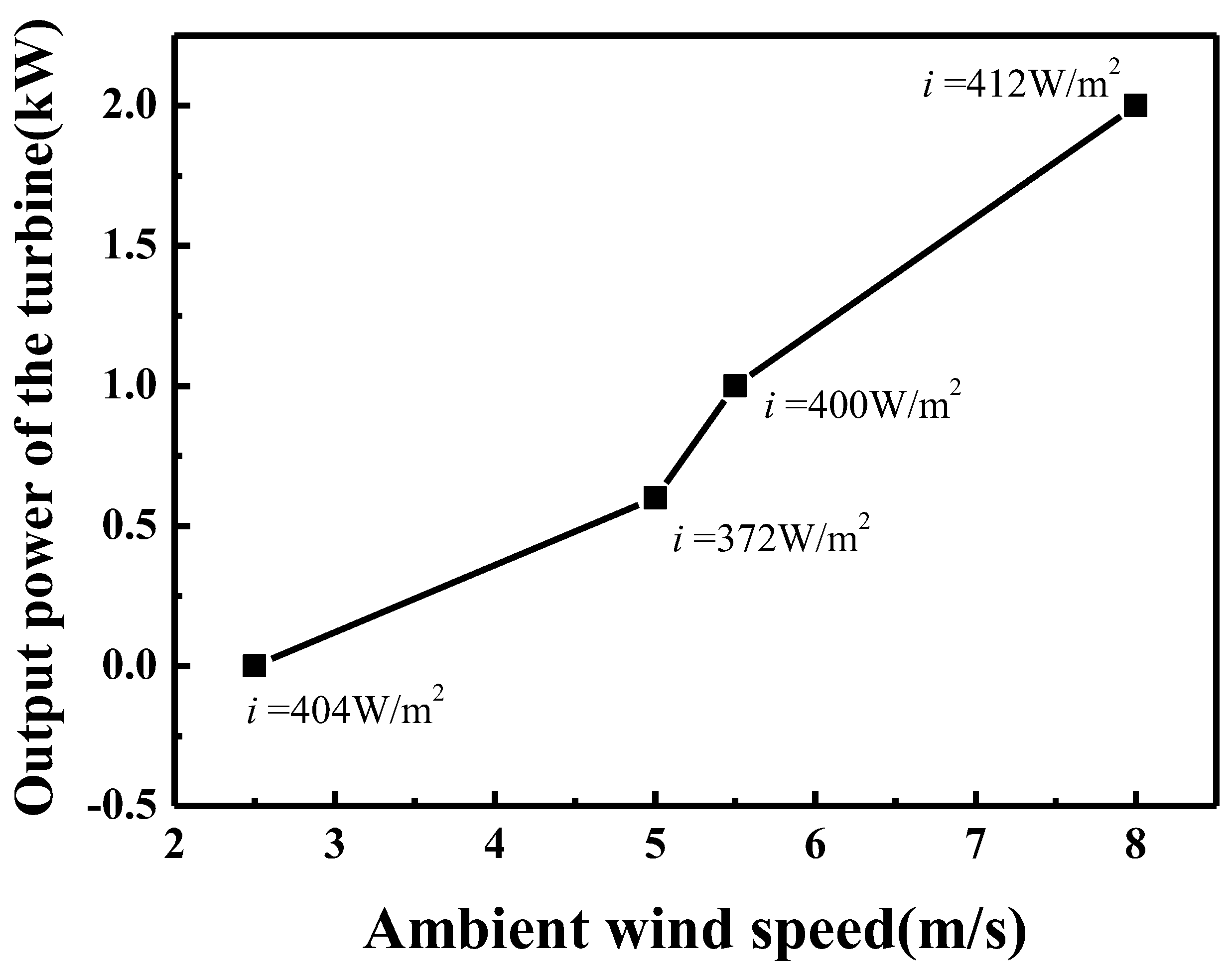
3.2.2. Effects of Ambient Wind Speed

The effects of ambient wind speed on the output power are shown in Figure 8. The variations in output power with regard to different ambient wind speeds were studied. The experimental data were measured at approximately 400 W/m2 solar radiation. i represents solar radiation. The result clearly shows that the ambient wind speed had a significant influence on the increase in the output power of the novel prototype. When the wind speed increases from 5 m/s to 8 m/s, the output power increases by 70%. This substantial increase underscores the importance of ambient wind speed as a critical parameter in the performance optimization of the SUTPP, especially when integrated with solar energy. These findings are instrumental for the strategic planning and design of SUTPPs, particularly in regions where wind speeds are variable, and underscore the potential for harnessing both solar and wind energy to achieve optimal energy output.

3.3. Numerical Results

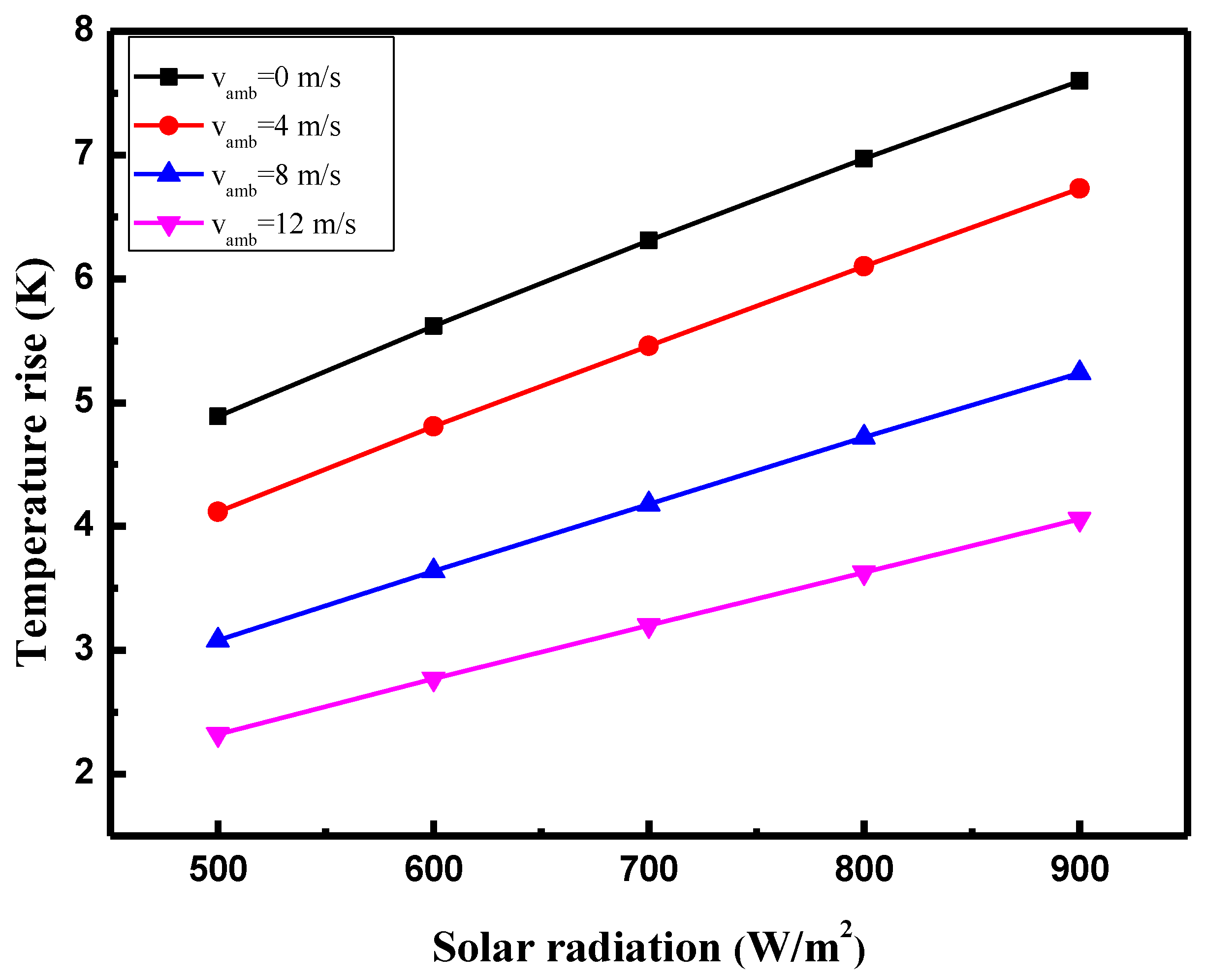
3.3.1. Temperature Rise at Tower Inlet

The coupling effects of the solar radiation and ambient wind speed on the temperature rise between the inlet of the collector and the tower bottom section are shown in Figure 9. The temperature rise was significantly influenced by solar radiation and the ambient wind speed. As shown in Figure 9, the temperature increased with the solar radiation at the same ambient wind speed. By contrast, the increase in the ambient wind speed caused a drop in the temperature. As increasing ambient wind speed results in an increased volume flow rate, the temperature will certainly decrease with more air volume heated under the same solar radiation intensity conditions.

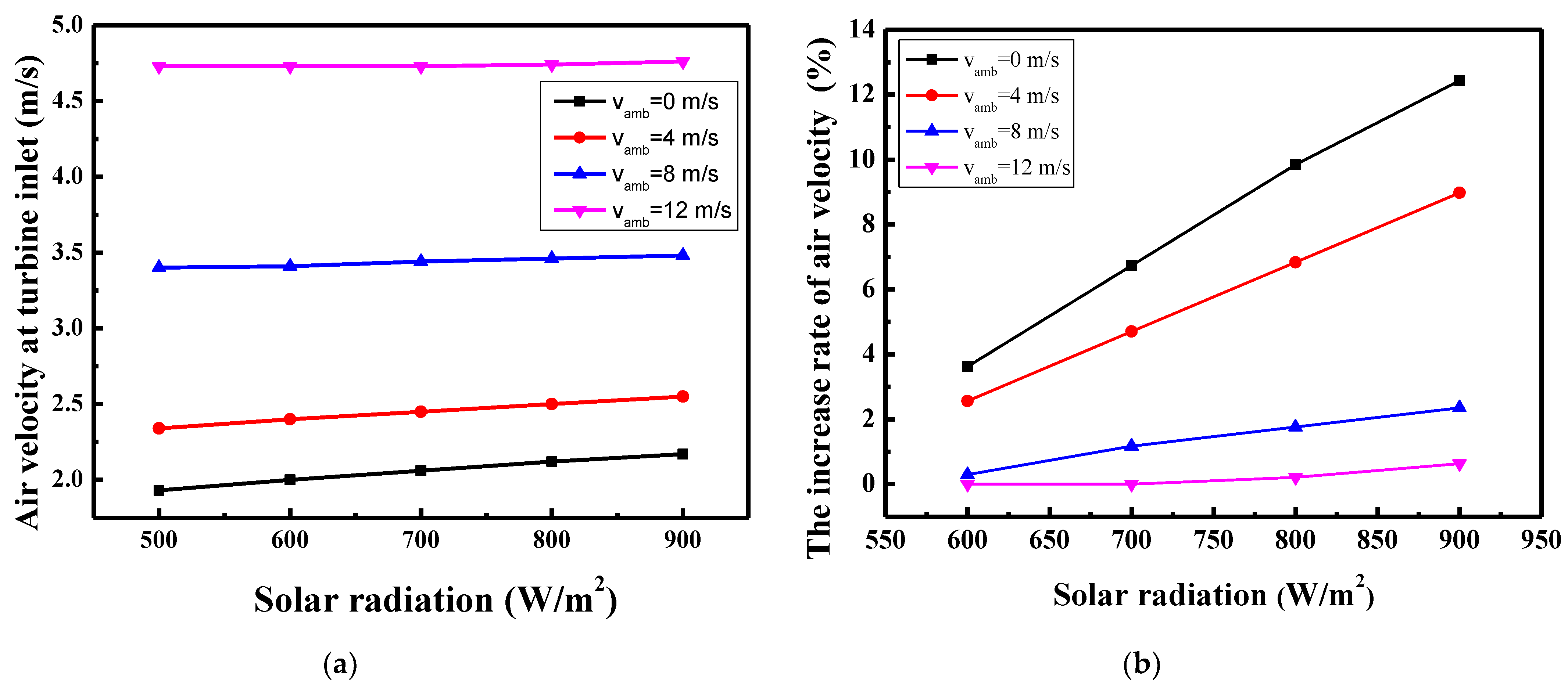
3.3.2. Air Velocity at Turbine Inlet

In contrast to traditional SUTTPs, this novel structure utilizes wind power. The wind intakes of the collector were fixed toward the prevailing northwesterly winds. As shown in Figure 10a, the air velocity at the turbine inlet increased with solar radiation and ambient wind speed. The increase rate of air velocity was used to give a quantitative assessment of the air velocity. The rate of air velocity increase is defined as v v a m b , i v v a m b , i = 500   W / m 2 v v a m b , i = 500   W / m 2 × 100 % ; vamb = 0, 4, 8, and 12 m/s, and i = 500, 600, 700, 800, and 900 W/m2. v v a m b , i is the air velocity at the turbine inlet under different ambient wind speeds and solar radiation conditions, v v a m b , i = 500   W / m 2 is the reference at different ambient wind speeds, v v a m b = 0 m / s , i = 500   W / m 2 = 1.93   m / s , v v a m b = 4   m / s , i = 500   W / m 2 = 2.34   m / s , v v a m b = 8   m / s , i = 500   W / m 2 = 3.4   m / s , and v v a m b = 12   m / s , i = 500   W / m 2 = 4.73   m / s . As shown in Figure 10b, the increase rate of the air velocity rose with the solar radiation. This rate more significantly increased at low ambient wind speeds and less significantly at high ambient wind speeds. As a result, the solar radiation had a more dominant influence on the increase rate of the air velocity in the collector at low ambient wind speeds. At high ambient wind speeds, the influence of solar radiation became less significant. The observed phenomenon of solar radiation having a less significant impact on the air velocity at the turbine inlet section at high wind speeds can be mainly attributed to the enhanced convective heat transfer within the collector at high wind speeds. Solar radiation contributes to heating the ground surface, which in turn heats the air above it. However, at high wind speeds, convective heat transfer is enhanced within the collector, and the surface is cooled down more rapidly by the wind, which can diminish the heating effect of solar radiation, thus limiting its ability to accelerate the air velocity at the turbine inlet.

3.3.3. Output Power

Figure 11a shows the variation in the turbine output with regard to the solar radiation at different ambient wind speeds; vamb = 0, 4, 8, and 12 m/s. Notably, the output power was influenced by the solar radiation and ambient wind speed. As shown in Figure 11a, the output power increased with the solar radiation and ambient wind speed. The influence of the ambient wind speed was more significant than that of solar radiation. Moreover, this SUTPP with a novel structure can be viewed as a conventional SUTPP when the ambient wind speed is 0 m/s. In most of the conventional SUTPPs, the collector is circular, and the tower is fixed at its center. In addition, the buoyancy caused by solar radiation is the only driving force that generates power. A comparison of the output power between present and previous simulation results ([47,49]) is presented in Table 2. The novel SUTPP was slightly less efficient than conventional SUTPPs in utilizing solar energy. This result may be caused by the novel structure of the SUTPP, which was designed to utilize wind power as a part of power generation. However, as the wind speed increases, the novel SUTPP shows a nuanced reduction in solar energy utilization efficiency, it offers a significant advantage in its ability to generate power through wind energy, thereby providing a more consistent and reliable power output. This innovative approach to integrating wind power into the SUTPP design presents a promising direction for the development of renewable energy systems that can operate effectively in diverse environmental conditions.
As the increasing trend in the output power with regard to solar radiation was not significant as shown in Figure 11a, the rate of output power increase was used to give a quantitative assessment of the influence of solar radiation. The increase rate of output power is defined as W v a m b , i W v a m b , i = 500   W / m 2 W v a m b , i = 500   W / m 2 × 100 % , W v a m b , i is the output power under different inlet wind speeds and solar radiation conditions, W v a m b , i = 500   W / m 2 is the reference at different inlet wind speeds. vamb = 0, 4, 8, and 12 m/s, and i = 500, 600, 700, 800, and 900 W/m2. At the solar radiation of 500 W/m2, W v a m b = 0   m / s , i = 500   W / m 2 = 0.78   W / m 2 , W v a m b = 4   m / s , i = 500   W / m 2 = 1.42   W / m 2 , W v a m b = 8   m / s , i = 500   W / m 2 = 4.39   W / m 2 , and W v a m b = 12   m / s , i = 500   W / m 2 = 11.75   W / m 2 . As the inlet wind speed increases from 4 to 12 m/s, the output power increases by 727%. The results of the increase rate of the output power are depicted in Figure 11b. When the ambient wind speed was 0 m/s, the output power was increased by 40% at 900 W/m2 compared with that at 500 W/m2. However, this variation in the output power became less significant with increasing ambient wind speeds. For instance, when the ambient wind speed reaches 16 m/s, we can barely observe any change in the output power at different solar radiation conditions. Thus, the influence of the solar radiation was more significant at low ambient wind speeds than at high ambient wind speeds.

4. Conclusions

In this study, we designed and built a novel SUTPP in the Jinsha Desert, which utilizes solar and wind energy. The details of the SUTPP structure were described, and experimental data were obtained. Both experimental and numerical studies were performed. For the experimental investigation, we obtained experimental data of the output power measured at different ambient wind speeds and solar radiation conditions. In the numerical investigation, a 3D numerical simulation of a novel SUTPP was carried out. Considerable attention was focused on the influences of the ambient wind speed and solar radiation. The experimental results showed that the output power of the SUTPP increased with the ambient wind speed and solar radiation. In the numerical simulation, the temperature increased with the solar radiation and decreased with the ambient wind speed. Solar radiation and ambient wind speed contributed to the increase in the air velocity at the turbine section. The numerical simulation provided more specific coupling effects of the ambient wind speed and solar radiation on the output power. At an ambient wind speed of 0 m/s, the SUTPP exhibited a 40% increase at a solar irradiation value of 900 W/m2 compared to 500 W/m2. However, the impact of solar irradiation on the output power diminished as ambient wind speeds increased. Notably, as the inlet wind speed rose from 4 m/s to 12 m/s, the output power witnessed a substantial increase of 727%. The numerical investigation indicated that the ambient wind speed was the dominant factor in the output power generation of the novel SUTPP, and the influence of the solar radiation was more significant at lower ambient wind speeds than at high speeds.
It is important to note that, while the design of the energy storage layer has been thoughtfully considered in this study, it has not yet undergone a process of optimization to maximize heat absorption and retention while minimizing heat loss. We intend to conduct simulations and small-scale tests in our future work. These will allow us to fine-tune the dimensions, materials, and arrangement of the components within the energy storage layer to achieve the best possible performance. Additionally, detailed analyses of the generation and energy costs between the novel SUTPP and traditional wind power plants, as well as classic SUTPPs, will be incorporated into our future research. This will allow us to comprehensively compare the technical feasibility of the new SUTPP with traditional technologies.

Author Contributions

Supervision, methodology, review and editing, and funding acquisition, Z.J.; conceptualization and resources, Y.W.; software, validation, and writing—original draft preparation, Q.W., M.C., X.Z. and L.R. All authors have read and agreed to the published version of the manuscript.

Funding

This work was financially sponsored by the National Natural Science Foundation of China (No. 52206109), the Shaanxi Province Key Research and Development Plan (No. 2024GX-YBXM-435), the Shaanxi Province Postdoctoral Research Project (No. 2023BSHTBZZ40), the Scientific Research Foundation of Xi’an University of Architecture and Technology (No. 1960321033), the National Natural Science Foundation of China (No. 52106111), and the Shaanxi Province Natural Science Basic Research Program (No. 2023-JC-YB-322).

Data Availability Statement

The data presented in this study are available on request from the corresponding author. The data are not publicly available due to the nature of this research.

Conflicts of Interest

The authors declare no conflicts of interest.

References

  1. Abdelsalam, E.; Almomani, F.; Azzam, A.; Juaidi, A.; Abdallah, R.; Shboul, B. Synergistic energy solutions: Solar chimney and nuclear power plant integration for sustainable green hydrogen, electricity, and water production. Process Saf. Environ. Prot. 2024, 186, 756–772. [Google Scholar] [CrossRef]
  2. Mehranfar, S.; Gharehghani, A.; Azizi, A.; Mahmoudzadeh Andwari, A.; Pesyridis, A.; Jouhara, H. Comparative assessment of innovative methods to improve solar chimney power plant efficiency. Sustain. Energy Technol. Assess. 2022, 49, 101807. [Google Scholar] [CrossRef]
  3. Das, P.; Chandramohan, V.P. A review on solar updraft tower plant technology: Thermodynamic analysis, worldwide status, recent advances, major challenges and opportunities. Sustain. Energy Technol. Assess. 2022, 52, 102091. [Google Scholar] [CrossRef]
  4. Saleh, M.J.; Atallah, F.S.; Algburi, S.; Ahmed, O.K. Enhancement methods of the performance of a solar chimney power plant: Review. Results Eng. 2023, 19, 101375. [Google Scholar] [CrossRef]
  5. Das, P.; Chandramohan, V.P. A review on recent advances in hybrid solar updraft tower plants: Challenges and future aspects. Sustain. Energy Technol. Assess. 2023, 55, 102978. [Google Scholar] [CrossRef]
  6. Belkhode, P.; Sakhale, C.; Bejalwar, A. Evaluation of the experimental data to determine the performance of a solar chimney power plant. Mater. Today Proc. 2020, 27, 102–106. [Google Scholar] [CrossRef]
  7. Onyango, F.N.; Ochieng, R.M. The potential of solar chimney for application in rural areas of developing countries. Fuel 2006, 85, 2561–2566. [Google Scholar] [CrossRef]
  8. Kasaeian, A.B.; Molana, S.; Rahmani, K.; Wen, D. A review on solar chimney systems. Renew. Sustain. Energy Rev. 2017, 67, 954–987. [Google Scholar] [CrossRef]
  9. Zhou, X.; Yang, J.; Xiao, B.; Shi, X. Special Climate around a Commercial Solar Chimney Power Plant. J. Energy Eng. 2008, 134, 6–14. [Google Scholar] [CrossRef]
  10. Al-Kayiem, H.H.; Aja, O.C. Historic and recent progress in solar chimney power plant enhancing technologies. Renew. Sustain. Energy Rev. 2016, 58, 1269–1292. [Google Scholar] [CrossRef]
  11. Haaf, W.; Friedrich, K.; Mayr, G.; Schlaich, J. Solar Chimneys Part I: Principle and Construction of the Pilot Plant in Manzanares. Int. J. Sol. Energy 1983, 2, 3–20. [Google Scholar] [CrossRef]
  12. Schlaich, J. Solar Chimney: Electricity from the Sun. 1996. Available online: https://www.semanticscholar.org/paper/Solar-Chimney%3A-Electricity-from-the-Sun-Schlaich/7faff4a4b0cd375de3bd87802d59672afbed1e2f?utm_source=direct_link (accessed on 3 August 2024).
  13. Schlaich, J.; Schafer, K.; Jennewein, M. Toward a consistent design of structural concrete. PCI J. 1987, 32, 74–150. [Google Scholar] [CrossRef]
  14. Zhou, X.; Wang, F.; Ochieng, R.M. A review of solar chimney power technology. Renew. Sustain. Energy Rev. 2010, 14, 2315–2338. [Google Scholar] [CrossRef]
  15. Sundararaj, M.; Rajamurugu, N.; Anbarasi, J.; Yaknesh, S.; Sathyamurthy, R. Parametric optimization of novel solar chimney power plant using response surface methodology. Results Eng. 2022, 16, 100633. [Google Scholar] [CrossRef]
  16. Pretorius, J.P.; Kröger, D.G. Critical evaluation of solar chimney power plant performance. Sol. Energy 2006, 80, 535–544. [Google Scholar] [CrossRef]
  17. Zhou, X.; Wang, F.; Fan, J.; Ochieng, R.M. Performance of solar chimney power plant in Qinghai-Tibet Plateau. Renew. Sustain. Energy Rev. 2010, 14, 2249–2255. [Google Scholar] [CrossRef]
  18. Saad, M.; Ahmed, N.; Mahmood, M.; Sajid, M.B. Performance enhancement of solar updraft tower plant using parabolic chimney profile configurations: A numerical analysis. Energy Rep. 2022, 8, 4661–4671. [Google Scholar] [CrossRef]
  19. Gholamalizadeh, E.; Chung, J.D. Analysis of fluid flow and heat transfer on a solar updraft tower power plant coupled with a wind turbine using computational fluid dynamics. Appl. Therm. Eng. 2017, 126, 548–558. [Google Scholar] [CrossRef]
  20. Balijepalli, R.; Chandramohan, V.P.; Kirankumar, K. Performance parameter evaluation, materials selection, solar radiation with energy losses, energy storage and turbine design procedure for a pilot scale solar updraft tower. Energy Convers. Manag. 2017, 150, 451–462. [Google Scholar] [CrossRef]
  21. Torabi, M.R.; Hosseini, M.; Akbari, O.A.; Afrouzi, H.H.; Toghraie, D.; Kashani, A.; Alizadeh, A.A. Investigation the performance of solar chimney power plant for improving the efficiency and increasing the outlet power of turbines using computational fluid dynamics. Energy Rep. 2021, 7, 4555–4565. [Google Scholar] [CrossRef]
  22. Keshari, S.R.; Chandramohan, V.P.; Das, P. A 3D numerical study to evaluate optimum collector inclination angle of Manzanares solar updraft tower power plant. Sol. Energy 2021, 226, 455–467. [Google Scholar] [CrossRef]
  23. Belkhode, P.N.; Shelare, S.D.; Sakhale, C.N.; Kumar, R.; Shanmugan, S.; Soudagar, M.E.M.; Mujtaba, M.A. Performance analysis of roof collector used in the solar updraft tower. Sustain. Energy Technol. Assess. 2021, 48, 101619. [Google Scholar] [CrossRef]
  24. Cuce, P.M.; Cuce, E.; Mandal, D.K.; Gayen, D.K.; Asif, M.; Bouabidi, A.; Alshahrani, S.; Prakash, C.; Soudagar, M.E.M. ANN and CFD driven research on main performance characteristics of solar chimney power plants: Impact of chimney and collector angle. Case Stud. Therm. Eng. 2024, 60, 104568. [Google Scholar] [CrossRef]
  25. Rezaei, L.; Saeidi, S.; Sápi, A.; Abdollahi Senoukesh, M.R.; Gróf, G.; Chen, W.-H.; Kónya, Z.; Klemeš, J.J. Efficiency improvement of the solar chimneys by insertion of hanging metallic tubes in the collector: Experiment and computational fluid dynamics simulation. J. Clean. Prod. 2023, 415, 137692. [Google Scholar] [CrossRef]
  26. Singh, A.P.; Singh, J.; Kumar, A.; Singh, O.P. Vertical limit reduction of chimney in solar power plant. Renew. Energy 2023, 217, 119118. [Google Scholar] [CrossRef]
  27. Eryener, D. Performance investigation of a solar updraft tower concept with downdraft windcatcher. Energy Convers. Manag. 2023, 286, 117055. [Google Scholar] [CrossRef]
  28. Praveen, V.; Chandramohan, V.P. Numerical study on optimization of fillet size on the chimney base of solar updraft tower plant for enhanced performance. Therm. Sci. Eng. Prog. 2022, 34, 101400. [Google Scholar] [CrossRef]
  29. Das, P.; Chandramohan, V.P. Computational study on the effect of collector cover inclination angle, absorber plate diameter and chimney height on flow and performance parameters of solar updraft tower (SUT) plant. Energy 2019, 172, 366–379. [Google Scholar] [CrossRef]
  30. Das, P.; Chandramohan, V.P. 3D numerical study on estimating flow and performance parameters of solar updraft tower (SUT) plant: Impact of divergent angle of chimney, ambient temperature, solar flux and turbine efficiency. J. Clean. Prod. 2020, 256, 120353. [Google Scholar] [CrossRef]
  31. Esmail, M.F.C.; A-Elmagid, W.M.; Mekhail, T.; Al-Helal, I.M.; Shady, M.R. A numerical comparative study of axial flow turbines for solar chimney power plant. Case Stud. Therm. Eng. 2021, 26, 101046. [Google Scholar]
  32. Xue, H.; Esmaeilpour, M. Power generation using solar energy: The effect of curved-guide vanes on the performance of a turbine in a solar chimney power plant. Sol. Energy 2022, 247, 468–484. [Google Scholar] [CrossRef]
  33. Balijepalli, R.; Chandramohan, V.P.; Kirankumar, K. Optimized design and performance parameters for wind turbine blades of a solar updraft tower (SUT) plant using theories of Schmitz and aerodynamics forces. Sustain. Energy Technol. Assess. 2018, 30, 192–200. [Google Scholar] [CrossRef]
  34. Bagheri, S.; Ghodsi Hassanabad, M. Numerical and experimental investigation of a novel vertical solar chimney power plant for renewable energy production in urban areas. Sustain. Cities Soc. 2023, 96, 104700. [Google Scholar] [CrossRef]
  35. Ali, M.H.; Kurjak, Z.; Beke, J. Modelling and simulation of solar chimney power plants in hot and arid regions using experimental weather conditions. Int. J. Thermofluids 2023, 20, 100434. [Google Scholar] [CrossRef]
  36. Esmail, M.F.C.; Khodary, A.; Mekhail, T.; Hares, E. Effect of wind speed over the chimney on the updraft velocity of a solar chimney power plant: An experimental study. Case Stud. Therm. Eng. 2022, 37, 102265. [Google Scholar] [CrossRef]
  37. Rushdi, M.A.; Yoshida, S.; Watanabe, K.; Ohya, Y. Machine learning approaches for thermal updraft prediction in wind solar tower systems. Renew. Energy 2021, 177, 1001–1013. [Google Scholar] [CrossRef]
  38. Zandian, A.; Ashjaee, M. The thermal efficiency improvement of a steam Rankine cycle by innovative design of a hybrid cooling tower and a solar chimney concept. Renew. Energy 2013, 51, 465–473. [Google Scholar] [CrossRef]
  39. Chen, Y.; Yang, Y.; Wei, Y. The Technology of Solar Heated Buoyancy driven flow Updraft Tower Power Plant and its Application in Wuhai desert of Inner Mongolia. Energy Res. Inf. 2010, 26, 117–121. [Google Scholar]
  40. Yang, Y.; Chen, Y.; Wei, Y. Experiments and CFD simulation of solar heated wind updraft tower power plant. J. Inn. Mong. Univ. Sci. Technol. 2010, 29, 62–65. [Google Scholar]
  41. Guo, P.; Wang, Y.; Li, J.; Wang, Y. Thermodynamic analysis of a solar chimney power plant system with soil heat storage. Appl. Therm. Eng. 2016, 100, 1076–1084. [Google Scholar] [CrossRef]
  42. Hasnain, S.M. Review on sustainable thermal energy storage technologies, Part I: Heat storage materials and techniques. Energy Convers. Manag. 1998, 39, 1127–1138. [Google Scholar] [CrossRef]
  43. Zhang, M.; Zhu, X.; Shi, J.; Liu, B.; He, Z.; Liang, C. Utilization of desert sand in the production of sustainable cement-based materials: A critical review. Constr. Build. Mater. 2022, 327, 127014. [Google Scholar] [CrossRef]
  44. Barzegar-Kalashani, M.; Seyedmahmoudian, M.; Mekhilef, S.; Stojcevski, A.; Horan, B. Small-scale wind turbine control in high-speed wind conditions: A review. Sustain. Energy Technol. Assess. 2023, 60, 103577. [Google Scholar] [CrossRef]
  45. Fuchs, F.W. Power Electronic Generator Systems for Wind Turbines; Springer Science and Business Media Deutschland GmbH: Berlin/Heidelberg, Germany, 2023; pp. 319–394. [Google Scholar]
  46. Hobbs, B.; Ord, A. Chapter 12—Fluid Flow. In Structural Geology; Hobbs, B., Ord, A., Eds.; Elsevier: Oxford, UK, 2015; pp. 365–421. [Google Scholar]
  47. Xu, G.; Ming, T.; Pan, Y.; Meng, F.; Zhou, C. Numerical analysis on the performance of solar chimney power plant system. Energy Convers. Manag. 2011, 52, 876–883. [Google Scholar] [CrossRef]
  48. Asnaghi, A.; Ladjevardi, S.M. Solar chimney power plant performance in Iran. Renew. Sustain. Energy Rev. 2012, 16, 3383–3390. [Google Scholar] [CrossRef]
  49. Zhou, X.; Yang, J.; Xiao, B.; Hou, G. Simulation of a pilot solar chimney thermal power generating equipment. Renew. Energy 2007, 32, 1637–1644. [Google Scholar] [CrossRef]
Figure 1. The photo of the established SUTPP and the monthly average temperature and monthly average solar irradiation in Wuhai. (a) The photo of the established SUTPP, (b) the monthly average solar irradiation and temperature, and (c) wind rise.
Buildings 14 02416 g001
Figure 2. Schematic of experimental setup. (a) Schematic of the SUTPP. (b) A 3D diagram of the experimental setup in the Jinsha Desert. (c) Diagrammatic top views of the experimental setup in the Jinsha Desert. (d) Interior design of the solar collector. 1—Toughened glass, 2—energy storage medium (desert sand), 3—pebble bed, 4—waterproof layer, 5—wind inlet, and 6—tower entrance.
Buildings 14 02416 g002
Figure 3. Experimental prototype in the Jinsha Desert. (a) Panoramic image of the experimental prototype. (b) Internal structure of the collector. (c) Entrance of the tower. (d) Internal structure of the tower. (e) Inverter unit.
Buildings 14 02416 g003
Figure 4. Simplified firmware of the control system.
Buildings 14 02416 g004
Figure 5. Independent test of the computational grid. The simulation boundary conditions were 700 W/m2 solar radiation and 13 m/s ambient wind speed.
Buildings 14 02416 g005
Figure 6. Validation for the numerical model.
Buildings 14 02416 g006
Figure 7. Variations in output power with regard to different solar radiations. Experimental data were measured at the ambient wind speed of approximately 5.5 m/s.
Buildings 14 02416 g007
Figure 8. Variation in output power with regard to different ambient wind speeds. The experimental data were measured at approximately 400 W/m2 solar radiation.
Buildings 14 02416 g008
Figure 9. Influence of solar radiation and ambient wind speed on the temperature rise in the collector. i = 500, 600, 700, 800, and 900 W/m2. vamb = 0, 4, 8, and 12 m/s.
Buildings 14 02416 g009
Figure 10. Influence of solar radiation and ambient wind speed on the air velocity at turbine inlet section. vamb = 0, 4, 8, and 12 m/s. i = 500, 600, 700, 800, and 900 W/m2. (a) Variations in air velocity and (b) variations in the increase rates of air velocity.
Buildings 14 02416 g010
Figure 11. Influence of solar radiation and ambient wind speed on the turbine output power. vamb = 0, 4, 8, and 12 m/s. i = 500, 600, 700, 800, and 900 W/m2. (a) Variation in the turbine output power and (b) variation in the rate of turbine output power increase.
Buildings 14 02416 g011
Table 1. Boundary conditions.
PlaceTypeDescription
Bottom of the collectorHeat flux500–900 W/m2
Surface of the canopyWallT = 293.15 K, 20 W / ( m 2 K )
Surface of the chimneyWall q = 0 W / ( m 2 K )
Collector inletPressure inlet P i n l e t = ρ v a m b 2 2
Chimney outletPressure outletAtmospheric pressure (1 atm)
Table 2. Comparison of the output power between present and previous simulation results.
ResultsRange of Solar RadiationRange of Output PowerRate of Output Power Increase
Present work500–900 W/m20.78–1.1 kW41.0%
Zhou [49]500–900 W/m23.4–5.5 W61.7%
Xu [47]500–900 W/m29.5–16 MW68.4%
Disclaimer/Publisher’s Note: The statements, opinions and data contained in all publications are solely those of the individual author(s) and contributor(s) and not of MDPI and/or the editor(s). MDPI and/or the editor(s) disclaim responsibility for any injury to people or property resulting from any ideas, methods, instructions or products referred to in the content.

