Article

Study on Deformation of New Tunnels Overcrossing Existing Tunnels Underneath Operating Railways

School of Traffic Engineering, Shandong Jianzhu University, Jinan 250101, China
*
Author to whom correspondence should be addressed.
Buildings 2024, 14(8), 2420; https://doi.org/10.3390/buildings14082420 (registering DOI)
Submission received: 30 May 2024 / Revised: 29 July 2024 / Accepted: 30 July 2024 / Published: 6 August 2024

Abstract

:
With the increasing utilization of urban underground space, new tunnels frequently intersect with existing tunnels and operational railways. However, sometimes the excavation and unloading of new tunnels can cause deformation of adjacent existing tunnels and railways, significantly affecting their normal operation. We used finite element software to predict the influence of new tunnel construction on overcrossing existing tunnels and down-traversing operational railways by a dynamic tunneling model based on a connection channel project of the east and west squares of a railway station. This article is not only control the distance between the two tunnels, but the new tunnel and the existing tunnel, as well as the new tunnel and the operation of the railway, the positional relationship between the three, the deformation laws of existing tunnels and operational railways during the construction of new tunnels with different buried depths are analyzed. The results show that the deformation curves of existing tunnels and operational railways present a normal distribution. The maximum deformation position is at the intersection with the new tunnel upon completion of the new tunnel excavation construction. Moreover, an increase in the buried depth of the new tunnel increases the deformation of the operational railway and the existing tunnel. The influence of the depth change of the new tunnel on the settlement of the operational railway is greater than that of the existing tunnel.

1. Introduction

In the course of urban development, given the limited space above ground, the development of underground transportation has emerged as an essential means for metropolitan progress. Nevertheless, as the development of underground transportation lags behind the process of spatial urbanization, and the construction of urban facilities is imperfect, underground transportation projects constructed in the later stage often intersect with existing above-ground projects and other underground ones. However, the construction of a new underground shield tunnel will lead to alteration of ground stress, which will inevitably exert a series of adverse effects on the adjacent above-ground and underground projects.
Many researchers have analyzed the impact of new tunnel construction on adjacent existing tunnels or operating railways. Different methods and models have been used to predict settlement during tunnel excavation [1,2]. Jin et al. [3] discuss several key factors influencing the settlement of existing tunnels, such as spatial position, support pressure, and tunnel stiffness, and propose an empirical equation for estimating the settlement of existing tunnels caused by the excavation of new shield tunnels. Feng et al. [4,5] derived the stress added under the action of shield tunneling based on a modified Gaussian formula and proposed a method for closely predicting stress-induced deformation of newly constructed tunnels under existing tunnels. He et al. and Li et al. [6,7] investigated the impact of shield tunnel excavation on rectangular pipe jacking and the surface, respectively. Zhang et al. [8] developed an analytical solution by utilizing Timoshenko beams placed on Kerr foundations, investigated the response of existing tunnels to the excavation of new tunnels underground, and examined the applicability of the proposed analytical solution through centrifuge laboratory tests and field measurements collected at a construction site. Ma et al. [9] conducted a three-dimensional numerical simulation to investigate the influence of overburden thickness and examined the distribution characteristics and variation of land subsidence. Within the range of 0.5 times the width of the central axis of the large pipe tunnel, cumulative ground settlement decreases linearly as the thickness of the casing increases. Cumulative settlement of the foundation rises with the increase in casing thickness. A simplified analysis method was proposed by Liang et al. [10], which considers the tunnel merely as a continuous Euler–Bernoulli beam with a certain equivalent flexural stiffness. When the existing tunnel is disregarded, the unloading stress caused by crossing the tunnel is calculated by the Mindlin solution. Fei et al. [11,12,13,14,15] used theoretical and numerical simulation methods to reveal the deformation patterns of existing shield tunnels deformed by newly constructed overpass tunnels. Furthermore, Zhang [16] and Pan [17] considered different construction parameters for sandy layer and water-rich strongly weathered sandstone layers to investigate deformation effects on operating railways during the construction of new tunnels under the railways and possible deformation-control measures. Shield tunnels also have different effects on railway tracks and roadbeds under different working conditions [18,19,20]. Mroueh H. and Shahrour I. [21] carried out a numerical investigation on the interaction between tunnels and adjacent structures in soft soil. The numerical simulation was performed through full three-dimensional computations, considering the existence of structures during tunneling. The analysis indicates that the force induced by the tunnel significantly depends on the presence of adjacent structures. The structural stiffness was disregarded in the tunnel-structure analysis, resulting in a serious overestimation of the internal force of the structural members. Hu [22] studied the axial force, bending moment, and pore water pressure of shield tunnel segments in soft and hard uneven strata, clay layers, and weathered granite strata of overlying buildings by establishing a rectangular element mechanical model based on the field test method. Zhang [23,24,25] studied the impact of a new tunnel on an existing tunnel through numerical analysis and verified the numerical analysis results of horizontal convergence displacement of the side wall of the new tunnel and longitudinal cracks of the existing tunnel through real-time monitoring. Zhang et al. [26,27,28] studied vertical deformation of the surface, arch foot, and ballast bed of the existing tunnel and analyzed in detail the effect of technical measures to control deformation of the existing shield tunnel. Therefore, it is of certain significance to study the influence of shield tunnel excavation on surrounding buildings [29,30]. Cheng’s [31] study shows that the force on the tunnel segments and the shield excavation speed are increasing. Too fast shield tunneling speed will lead to an increase of tunnel segment load and aggravate uneven distribution of grouting pressure.
There have been many studies focused on the deformation of newly built tunnels crossing existing tunnels or operating railways. However, there are only a few studies investigating construction of shield tunnels in complex environments. Therefore, this paper takes the underground connecting passage of the east and west squares of a railway station as the engineering background. The newly built shield tunnel is in a complex environment, spanning the subway tunnel and beneath the railway. Aiming at the new shield tunnel project in a complex environment, this paper utilizes finite element software to establish six distinct numerical models with buried depths of 5 m, 7 m, 9 m, 11 m, 13 m, and 15 m, which are employed to simulate and calculate the influence of underground connection channels with different buried depths on adjacent subway tunnels and operational railways in a complex environment. The deformation patterns of the existing tunnel and operating railway during the dynamic tunneling of the new shield tunnel under different buried depths are analyzed. This study offers the theoretical basis for determining the location of the new shield tunnel and the rational utilization of underground space and provides a reference for on-site construction and similar projects.

2. Project Overview

The project is the construction of a shield tunnel that serves as an underground pedestrian exchange channel between the east and west squares of a railway station. The channel crosses Metro Line 1 at an angle of 34.2° and crosses four tracks of the operating railway. The positions of the newly constructed tunnel, the overlying subway tunnel, and the operating railway are shown in Figure 1.
The outer diameter and inner diameter of the existing subway tunnel segments are 6 m and 5.5 m, respectively, with a width of 2 m and a thickness of 0.25 m. The outer and inner diameters of the newly constructed shield tunnel segments are 6 m and 5.5 m, with a width of 2 m and a thickness of 0.25 m. According to the geological survey, the surface layer is composed of artificial miscellaneous fill soil, and below it is silt formed by recent quaternary alluvial deposits consisting of silty clay. The groundwater level of the site is approximately 10.5–11.7 m below the natural ground level (with an elevation of approximately 91.0 m), corresponding to the quaternary loose rock pore water. The main sources of groundwater recharge are atmospheric precipitation infiltration recharge and groundwater runoff recharge, with the main discharge methods being artificial extraction and groundwater runoff. The annual variation in the groundwater level at the site is approximately 1.0–2.0 m, and the highest water level at the site within 3–5 years was approximately 8.0 m (elevation of approximately 94.0 m). The historically highest groundwater level is at a depth of approximately 6.0 m underground (elevation 96.0 m).

3. Numerical Simulation

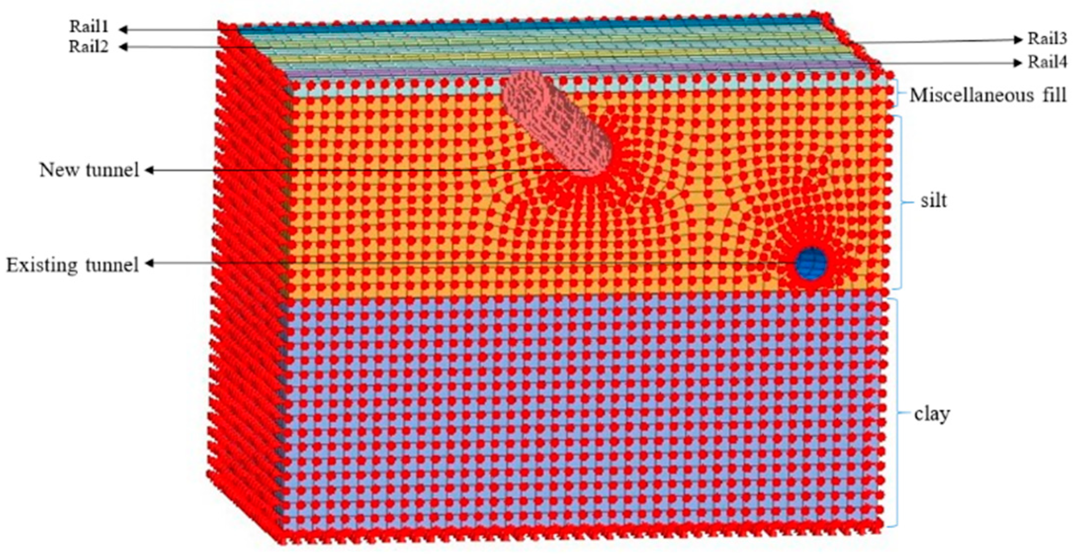
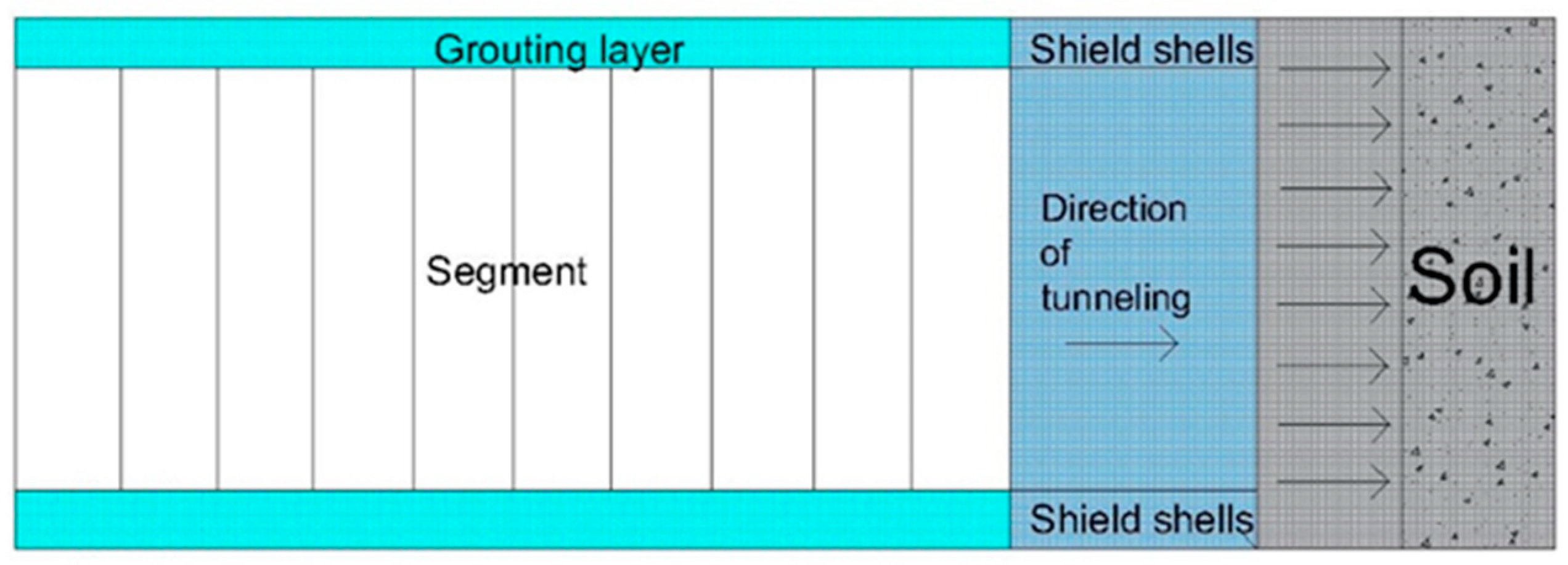
3.1. Model Establishment

MIDAS GTS NX 2021 software was used to create a comprehensive three-dimensional model based on the spatial relationships among the new shield tunnel, existing tunnel, and operating railway. The model establishes boundary constraints around and beneath the soil mass, considering the soil mass as infinite and keeping the top surface of the soil mass free at the same time. The distance from the lateral boundary of the model and the distance between the lower bound of the model from top should be taken as sufficient, so that the effects of the boundaries in the numerical model was minimized. The displacement and the stress contours in the finite element software indicate that this distance is sufficient. The model is divided into 531,700 units within an 80 m × 40 m × 60 m space, with a simulated excavation depth of 2 m (Figure 2). Different vertical clearances between the new shield tunnel and both the operating railway (S1) and existing tunnel (S2) are analyzed (5, 7, 9, 11, 13, and 15 m) to simulate and analyze the deformation of the existing tunnels and operational railways during the excavation of new underpass tunnels. The specific working conditions are detailed in Table 1, and the grid calibration is automatically inspected and calibrated by the software.

3.2. Calculation Parameters and Operating Conditions

Solid elements are used to simulate the segments, existing tunnels, grouting, shield shells, and strata. The segments, existing tunnels, and grouting layers are based on elastic constitutive models, while others are based on Mohr–Coulomb elastoplastic constitutive models. The calculation parameters are listed in Table 2 and Table 3.
The surface of the model is free, while all other surfaces constrain normal displacement. A built-in function of the simulation software is used to automatically divide the solid mesh into tetrahedral elements with four nodes. According to Code for Design of Railway Bridges and Culverts [32], the calculation model must apply ZKH live load, uniformly distributed load, concentrated load, and concentrated load at the center of the road surface.
The softening modulus method is used to simulate the release of stress during excavation. For simulating shield tunnel excavation, MIDAS GTS NX is used to analyze the activation and passivation of elements. Firstly, the element is “activated,” then the excavated soil element is “passivated,” and some node forces are released. Finally, the lining element of the pipe segment is “changed in attributes,” and all other node forces are released. The simulation of the shield tunnel excavation is presented in Figure 3, and the calculation conditions are listed in Table 4.

4. Analysis of Calculation Results

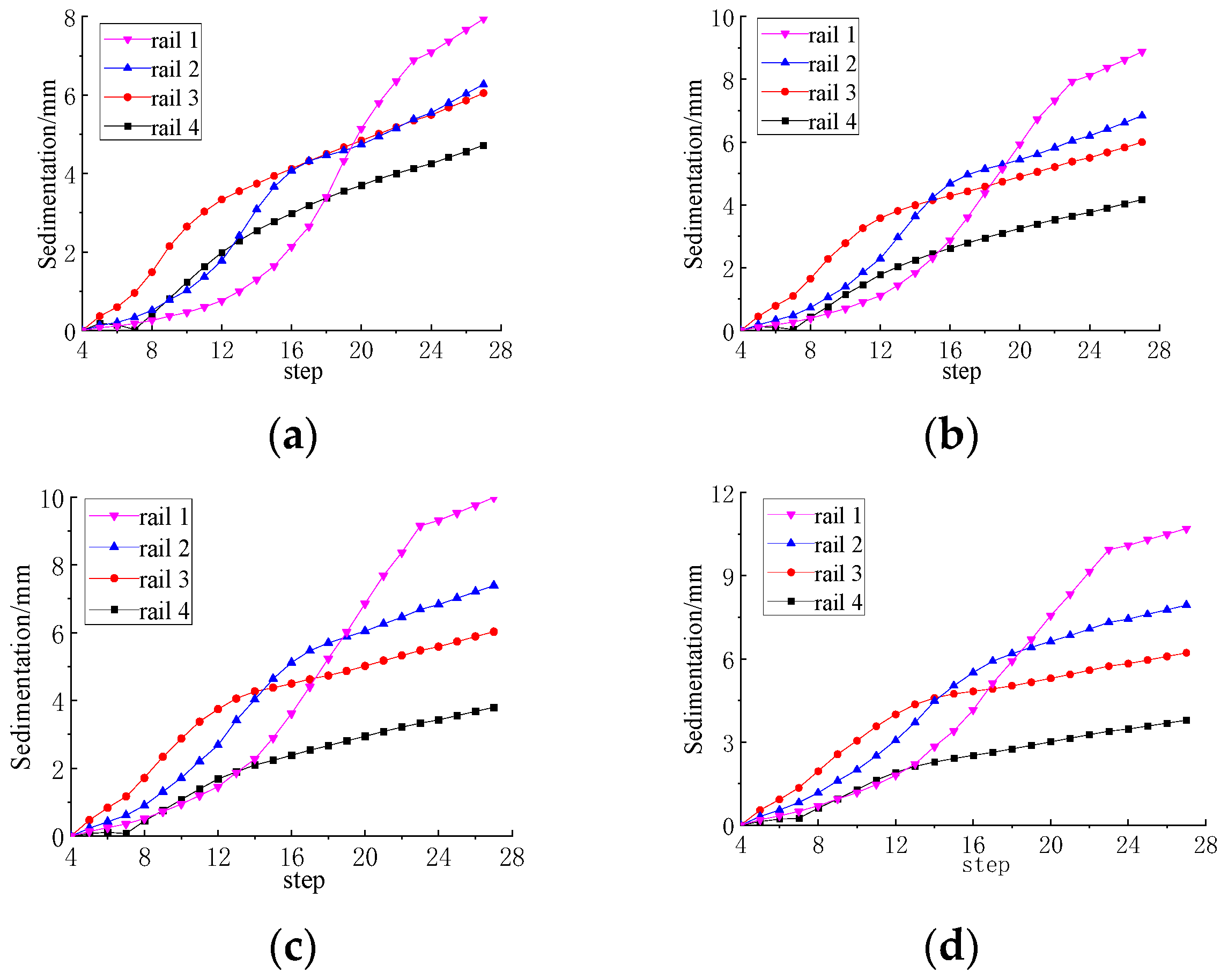
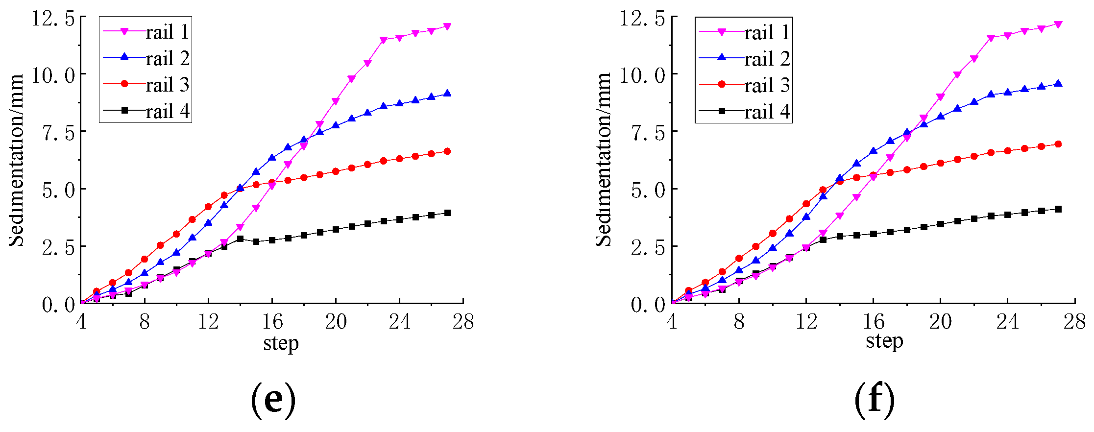
4.1. Impact of New Tunnels on Operating Railways

The cloud map of railway track settlement after completion of the new tunnel excavation is shown in Figure 4. The maximum settlement position of each track is at the intersection of the newly built tunnel and the operating railway. The self-intersection is symmetrically distributed along both sides of the tracks with an impact range of 30 m on both sides of the track, which conforms to a normal distribution.
The maximum settlement curve of the operating railway track corresponding to different steps in the construction of the new tunnel is depicted in Figure 5. As shown in Figure 5, under different burial depths, with the excavation of the new tunnel, the settlement of rail 1, rail 2, rail 3, and rail 4 increases continuously. After completion of construction, maximum settlement of rail 1 is achieved, and as the burial depth increases, rail 1’s maximum settlement continuously increases; the maximum settlement value of rail 1 is 12.2 mm (when S1 = 15 m). During the process of construction, new tunnels must not be buried too deep, and corresponding reinforcement measures should be adopted for operating railways.
Taking railway track 2, for example, Figure 6 shows that in the range of 1D to 3D buried depth, the maximum settlement of the operating railway increases with the increase of the buried depth S1. This is because the self-bearing capacity of the surrounding rock cannot be fully utilized when the buried depth of the tunnel is shallow. With the increase of tunnel buried depth, the self-weight stress and self-bearing capacity of surrounding rock will increase, too, while the growth rate of the self-bearing capacity of surrounding rock is relatively less. Due to the limitation of the actual distance between the operating railway and the existing tunnel, this paper does not study the situation in which the buried depth of the tunnel is greater than 3D. Combined with the research results of the literature [33], when the buried depth of the tunnel is greater than 3D, the surface settlement decreases with the increase of the buried depth of the tunnel. As the excavation of the new tunnel steps proceed, the rate of settlement also undergoes certain changes, and these changes can be divided into the following stages: the advanced-deformation stage, the intensified-deformation stage, and the slow-deformation stage. Tunnel excavation causes disturbances to the soil around the operating railway, but the rate of settlement change at this time is low; this is the advanced deformation stage. During the construction step, it is the highest when the location of the construction is directly below the operating railway. The rate of settlement change is the highest in the stage of intensified deformation. Owing to the application of shield tail compensation grouting and lining, the settlement deformation of the operating railway slows down in the slow-deformation stage.

4.2. Deformation of Existing Tunnels

The total displacement cloud map of the arch of the existing tunnel is shown in Figure 7 for the condition in which the deformation of the existing tunnel is S2 = 11 m. From the figure, it can be seen that, after construction of the new tunnel, the arch of the existing tunnel undergoes uneven deformation. The closer the existing tunnel is to the intersection of the new and old tunnels, the greater the total deformation, with a maximum value of 1.19 mm. Moreover, the extent of overall deformation of the existing tunnel is substantial in the middle and small on both sides, which conforms to a normal distribution. When the S2 value is 9, 7, 5, 3, and 1 m, the deformation patterns are consistent with that at S2 = 11 m. Due to space limitations, we will not elaborate further.
The total displacement curve of the existing tunnel arch during the excavation of new tunnels at different burial depths is shown in Figure 8. As the new tunnel excavation progresses, the maximum total displacement of the arch continuously increases and eventually remains unchanged. During excavation and construction of a new tunnel, the total displacement rate of the existing tunnel arch increases with the decrease in the S2 value. When the S2 value is between 7 m and 11 m (i.e., the vertical clear distance is 1–2D, where D is the diameter of the new tunnel), the total displacement rate of the existing tunnel arch is relatively low. When S2 is between 1 m and 5 m (i.e., the vertical clear distance is 0–1D), the total displacement of the existing arch crown changes rapidly and tends to stabilize at the 14th construction step. The maximum total displacement of the arch of the existing subway tunnel gradually increases with the decrease in the value of S2. When S2 = 1 m, the maximum total displacement of the arch is 6.66 mm. In actual construction, the location of the new tunnel needs to be reasonably selected by considering the potential deformation of the underpass operating railway and by taking corresponding settlement-control measures.

5. Conclusions

During shield construction of urban subway tunnels, it is inevitable that existing underground pipelines, building foundations, subway stations, existing subway tunnels, and other related underground structures will be traversed and overridden underground. The construction of tunnel shields causes soil disturbance, which affects the stability of related structures and even leads to functional damage to existing structures and accidents. Based on the east–west square connecting passage project of a railway station, this paper establishes a dynamic tunnel connection model using finite element software and discusses the influence of the construction of the new tunnel on the existing tunnel crossing and down-running railway. Moreover, it also analyzes the deformation of the existing tunnel and the operating railway under the construction condition of the new tunnel at different buried depths by controlling the distance between the existing tunnel and the new tunnel.
(1)
The excavation of new shield tunnels can cause uneven deformation of adjacent existing tunnels and operating railways. In the burial depth range of 1 to 3D, the impact of the construction of a new shield tunnel on the deformation of existing tunnels and operating railways increases with the burial depth of the new tunnel.
(2)
After completion of new shield tunneling construction, both the operating railway and the existing tunnel exhibit maximum deformation at the intersection with the new tunnel, gradually decreasing from the center point toward both sides and following a normal distribution.
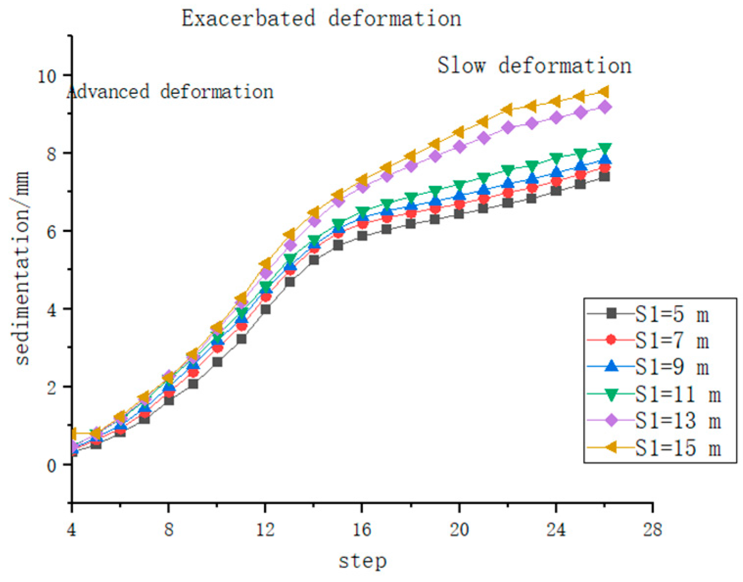
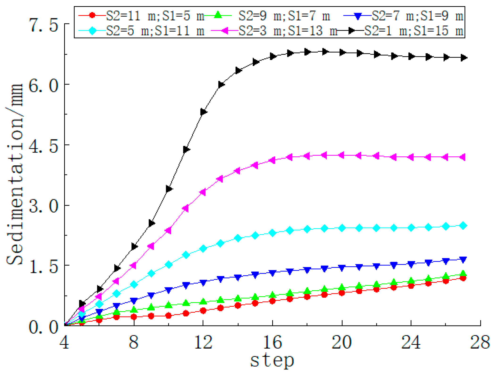
(3)
As construction of the new tunnel progresses, the settlement changes of the operating railways can be divided into three stages: the advanced-deformation stage, intensified-deformation stage, and slow-deformation stage. During excavation and construction of a new tunnel, the rate of change in the total displacement of the existing tunnel arch increases with the decrease in the value of S2.
(4)
For the existing tunnel, when the buried depth is shallow, the deformation of the second stage (strengthening deformation stage) constitutes 42.8% of the principal deformation. However, with the progressive increase in buried depth, the proportion of the first stage gradually rises and eventually reaches 70%. The principal deformation is concentrated in the first (advanced-deformation) and the second (strengthening deformation) stages, each accounting for approximately 40%, and the third stage merely accounts for approximately 13%.

Author Contributions

Conceptualization, C.X. and Y.Q.; Methodology, C.X. and Y.Q.; Software, C.X., Y.Q. and H.L.; Data curation, C.X., Y.Q., H.L. and S.S.; Writing—original draft, C.X. and Y.Q.; Writing—review and editing, C.X., Y.Q., S.S. and H.L. All authors have read and agreed to the published version of the manuscript.

Funding

This research was funded by Shandong Province Higher Education Youth Innovation Technology Support Program Project, grant number 2021KJ058, and the Shandong Jianzhu University College Student Innovation and Entrepreneurship Competition Project (GCX23019501).

Data Availability Statement

The raw data supporting the conclusions of this article will be made available by the authors on request.

Conflicts of Interest

The authors declare no conflicts of interest.

References

  1. Jin, D.L.; Shen, X.; Yuan, D.J. Theoretical Analysis of Three-dimensional Ground is Placements Induced by Shield Tunneling. Appl. Math. Model. 2020, 79, 85–105. [Google Scholar] [CrossRef]
  2. Liang, R.Z. Simplified Analytical Method for Evaluating the Effects of Overcrossing Tunnelling on Existing Shield Tunnels Using the Nonlinear Pasternak foundation model. Soils Found. 2019, 59, 1711–1727. [Google Scholar] [CrossRef]
  3. Jin, D.L.; Yuan, D.J.; Li, X.G.; Zheng, H.T. Analysis of the Settlement of an Existing Tunnel Induced by Shield Tunneling Underneath. Tunn. Undergr. Space Technol. 2018, 81, 209–220. [Google Scholar] [CrossRef]
  4. Feng, G.H.; Xu, C.J.; Zheng, M.W. Study of Tunnel-soil Interaction Induced by Tunneling Underlying. Eng. Mech. 2023, 40, 59–68. [Google Scholar]
  5. Feng, G.H. Deformation Response Analysis on Existing Tunnel Caused by Shield Tunneling Underlying Considering Axial Internal Force. J. Southeast Univ. (Nat. Sci. Ed.) 2022, 53, 523–529. (In Chinese) [Google Scholar]
  6. He, J.; Yang, Z.; Zhang, X. Effect of Undercrossing Shield Tunnels Excavation on Existing Rectangular Pipe-Jacking Tunnels. Appl. Sci. 2023, 13, 12235. [Google Scholar] [CrossRef]
  7. Li, Y.; Bian, X.; Peng, H.; Zhu, B.; Zhou, Y. Additional Stress of Soil and Surface Settlement during Tunnel Shield Construction. Buildings 2023, 13, 1437. [Google Scholar] [CrossRef]
  8. Zhang, D.M.; Huang, Z.K.; Li, Z.L.; Zong, X.; Zhang, D.M. Analytical Solution for the Response of an Existing Tunnel to a New Tunnel Excavation Underneath. Comput. Geotech. 2018, 108, 197–211. [Google Scholar] [CrossRef]
  9. Ma, S.J.; Li, M.Y.; Jin, J.W.; Bai, K. The Influence of Shallow Buried Double-line Parallel Rectangular Pipe Jacking Construction on Ground Settlement Deformation. Alex. Eng. J. 2021, 60, 1911–1916. [Google Scholar] [CrossRef]
  10. Liang, R.Z.; Xia, T.D.; Hong, Y.; Yu, F. Effects of above-crossing Tunnelling on the Existing Shield Tunnels. Tunn. Undergr. Space Technol. 2016, 58, 159–176. [Google Scholar] [CrossRef]
  11. Fei, R.; Peng, L.; Zhang, C.; Zhang, J.; Zhang, P. Experimental and Numerical Studies of a Shield Twin Tunnel Undercrossing the Existing High-Speed Railway Tunnel. Geotech. Geol. Eng. 2024, 42, 1871–1886. [Google Scholar] [CrossRef]
  12. Liu, H.Y.; Small, J.C.; Carter, J.P.; Williams, D.J. Effects of Tunnelling on Existing Support Systems of Perpendicularly crossing Tunnels. Comput. Geotech. 2009, 36, 880–894. [Google Scholar] [CrossRef]
  13. Chen, H.D.; Shen, W.M.; Zhang, W.J. Viscoelastic Analysis of Deformation of the Existing Tunnel Due to the Above-Crossing Tunneling. Chin. Q. Mech. 2022, 43, 958–969. (In Chinese) [Google Scholar]
  14. Liu, H.Y.; Small, J.C.; Carter, J.P. Full 3D Modelling for Effects of Tunnelling on Existing Support Systems in the Sydney Region. Tunn. Undergr. Space Technol. 2008, 23, 399–420. [Google Scholar] [CrossRef]
  15. Luo, C.S.; Cheng, Y.H.; Bai, Z.; Shen, T.; Wu, X.Y.; Wang, Q.G. Study on Deformation Law of Subway Construction under Passing Existing Line in Short Distance. Adv. Civ. Eng. 2021, 2021, 6626927. [Google Scholar] [CrossRef]
  16. Zhang, R.; Xiong, H.; Su, D.; Han, W.; Li, Q.; Chen, X. Micromechanical Investigation into the Mechanism of Slurry Fracturing and the Effect of Covering Depth Concerningshield Tunneling in a Sandy Stratum. Tunn. Undergr. Space Technol. 2024, 144, 105538. [Google Scholar] [CrossRef]
  17. Pan, P.; Chen, W.; Zheng, J.C. Construction Technology of Pipe-jacking Tunnel in Water-rich Intensely Weathered Sandstone Formation crossing underneath Existing Railway. Sci. Technol. Eng. 2023, 23, 12714–12720. (In Chinese) [Google Scholar]
  18. Fang, M.; Zhou, C.Y.; Liu, Z. Influence of Construction Parameters and Cross Angle on Existing Tunnel Settlement During undercrossing Shield Tunneling Construction. Eng. Mech. 2011, 28, 133–138. (In Chinese) [Google Scholar]
  19. Li, S. Monitoring and Early Warning of Subgrade Settlement for High Speed Railway Undercrossed by Shield Tunnel. Railw. Eng. 2023, 63, 127–130. (In Chinese) [Google Scholar]
  20. Liu, X.; Fang, H.C.; Jiang, A.N.; Zhang, D.L.; Fang, Q.; Lu, T.; Bai, J.R. Mechanical Behaviours of Existing Tunnels Due to Multiple-tunnel Excavations Consideringconstruction Sequence. Tunn. Undergr. Space Technol. 2024, 152, 105870. [Google Scholar] [CrossRef]
  21. Mroueh, H.; Shahrour, I. A full 3-D Finite Element Analysis of Tunneling-adjacent Structures Interaction. Comput. Geotech. 2003, 30, 245–253. [Google Scholar] [CrossRef]
  22. Hu, H.; Xue, T.; Li, J.; Liu, P.; Wang, B.; Liu, Y. Mechanical Performance of Concrete Segment Lining Structure of Shield Tunneling in Different Strata. Buildings 2023, 13, 3118. [Google Scholar] [CrossRef]
  23. Xiang, P.; Wei, G.; Jiang, H.; Ding, Y.; Guo, H.; Zhang, R. Experimental Study and Theoretical Analysis of the Effect of Surcharge/Unloading at Both Sides of the Ground Surface on an Existing Shield Tunnel at Different Burial Depths. Buildings 2023, 13, 1911. [Google Scholar] [CrossRef]
  24. Wang, C.W.; Liu, X.L.; Song, D.Q.; Wang, E.Z.; He, Z.H.; Tan, R.S. Structural response of former Tunnel in the Construction of Closely-Spaced cross-river Twin Tunnels. Tunn. Undergr. Space Technol. 2024, 147, 105652. [Google Scholar] [CrossRef]
  25. Ding, Z.; Zhang, X.; He, S.H.; Qi, J.Y.; Lin, G.C. Experimental and Theoretical Study on Longitudinal Deformation and Internal Force of Shield Tunnel under Surcharge. Tunn. Undergr. Space Technol. 2024, 144, 105506. [Google Scholar] [CrossRef]
  26. Zhang, Y.; Tao, L.; Liu, J.; Zhao, X.; Guo, F.; Tan, L.; Wang, Z. Construction Techniques and Mechanical Behavior of Newly-built Large-Span Tunnel Ultra-short Distance up-crossing the Existing Shield Tunnel with Oblique Angle. Tunn. Undergr. Space Technol. 2023, 138, 105162. [Google Scholar] [CrossRef]
  27. Yao, J.; Wang, Z.; Li, Z.; Xiao, X.; Wu, H.; Ma, W.; Huo, Z.; Pu, Y. Research on Structural Deformation Law and Allowable Deformation of Shield Tunnel Underneath Passing High-Speed Railway Tunnel. Proc. SPIE-Int. Soc. Opt. Eng. 2021, 12058, 758–764. [Google Scholar] [CrossRef]
  28. Shi, Y.; Lin, L.; Xu, J.; Qing, J. Analysis of Construction Mechanics of Expansive Soil Tunnel Passing Through Existing subway station in short distance Under humidification Condition. J. Railw. Sci. Eng. 2020, 18, 200–210. [Google Scholar] [CrossRef]
  29. Zhu, Q.L.; Ding, Y.P. Impact of New undercrossing Tunnel Excavation on the Stability of the Existing Tunnel. Front. Earth Sci. 2022, 10, 915882. [Google Scholar] [CrossRef]
  30. Wu, K.; Zheng, Y.; Li, S.; Sun, J.; Han, Y.; Hao, D. Vibration Response Law of Existing Buildings Affected by Subway Tunnel Boring Machine Excavation. Tunn. Undergr. Space Technol. 2021, 120, 104318. [Google Scholar] [CrossRef]
  31. Cheng, Y.; Liu, X. Research on the Pressure Distribution Law of Synchronous Grouting in ShieldTunnels and the Force on Segments. Buildings 2024, 14, 1099. [Google Scholar] [CrossRef]
  32. TB 10002-2017; Code for Design on Railway Bridge and Culvert. National Railway Administration: Beijing, China, 2017.
  33. Yan, P.F. Three-dimensional Finite element Analysis of Influence by Excavation of different buried Tunnels on Ground Subsidence. J. Guangxi Univ. 2021, 46, 60–66. [Google Scholar]
Figure 1. The positions of the new tunnel, the upper subway tunnel, and the operating railway. (a) Front view; (b) top view.
Buildings 14 02420 g001
Figure 2. Calculation model.
Buildings 14 02420 g002
Figure 3. Schematic diagram of simulated excavation of shield tunnel.
Buildings 14 02420 g003
Figure 4. Settlement cloud map of the operational railway track after completion of new tunnel construction. (a) S1 = 5 m; (b) S1 = 7 m; (c) S1 = 9 m; (d) S1 = 11 m; (e) S1 = 13 m; (f) S1 = 15 m.
Buildings 14 02420 g004
Figure 5. Maximum settlement curve of railway tracks under different construction steps of the new tunnel (a) S1 = 5 m; (b) S1 = 7 m; (c) S1 = 9 m; (d) S1 = 11 m; (e) S1 = 13 m; (f) S1 = 15 m.
Buildings 14 02420 g005aBuildings 14 02420 g005b
Figure 6. Variation curve of track 2 settlement with construction steps under different S1 values.
Buildings 14 02420 g006
Figure 7. Cloud image of the total displacement of the arch roof of the existing tunnel when S2 = 11 m.
Buildings 14 02420 g007
Figure 8. Variation curve of existing tunnel settlement with construction steps under different burial depths.
Buildings 14 02420 g008
Table 1. Different buried depths of new tunnels.
ModelS1S2
15 m11 m
27 m9 m
39 m7 m
411 m5 m
513 m3 m
615 m1 m
Table 2. Formation parameters.
StratumModulus of Elasticity
KN/m2
Poisson’s RatioUnit Weight
KN/m3
Cohesion KN/m2Internal Friction Angles °
Miscellaneous fill15,0000.4218515
silt20,0000.4182025
clay40,0000.35202536
Table 3. Supporting parameters.
TypeModulus of Elasticity
KN/m2
Poisson’s RatioUnit Weight
KN/m3
railway31.50.220
lining segment31.50.2525
shield shell34.50.2525
slip casting28.00.2525
Table 4. Construction step.
StepStep Content
1Initial stress balance
2Displacement clearing
3Subway operation
4Displacement clearing
5–23Inner and outer diameter excavation, shield application
7–26Segment construction and grouting simulation
Disclaimer/Publisher’s Note: The statements, opinions and data contained in all publications are solely those of the individual author(s) and contributor(s) and not of MDPI and/or the editor(s). MDPI and/or the editor(s) disclaim responsibility for any injury to people or property resulting from any ideas, methods, instructions or products referred to in the content.

