Article

The Hysteresis Behavior of Steel Beam–Column Joint with the Load Bearing-Energy Dissipation Connection for Converter Station Building

1
Economic and Technological Research Institute of State Grid Fujian Electric Power Co., Ltd., Fuzhou 350013, China
2
State Grid Fujian Electric Power Co., Ltd., Fuzhou 350013, China
3
School of Civil Engineering, Fujian University of Technology, Fuzhou 350108, China
*
Author to whom correspondence should be addressed.
Buildings 2024, 14(8), 2424; https://doi.org/10.3390/buildings14082424 (registering DOI)
Submission received: 27 June 2024 / Revised: 1 August 2024 / Accepted: 2 August 2024 / Published: 6 August 2024
(This article belongs to the Special Issue High-Performance Composite Construction: Materials and Components)

Abstract

:
Prefabricated converter station building has been gradually applied in the field of power engineering construction due to the advantages of standardized design, high construction efficiency, and quality control. The beam–column joint is the essential constitutive part to ensure structural integrity and reliable force transmission for the prefabricated structure. In this paper, a novel load bearing-energy dissipation connection is proposed and applied to the beam–column joint to improve seismic performance and seismic resilience. Pseudo-static tests were conducted on the beam–column joint with the load bearing-energy dissipation connection, and the test results demonstrated that the tested beam–column joints developed with similar failure modes, and the damage was concentrated in the load bearing-energy dissipation connection while the beam and column remained elastic. The beam–column joint with the load bearing-energy dissipation connection had stable hysteresis behavior, with favorable bearing capacity and energy dissipation behavior. A shorter slip length and a larger bolt distance could lead to better stress development and enhance the bearing capacity, while the slip length barely affected the ductile behavior. Moreover, a finite element model was established and validated to extend the parametric study to provide a preliminary understanding of the mechanical mechanism of the proposed beam–column joint with the load bearing-energy dissipation connection. It was confirmed that the load–-deformation behavior was greatly affected by the slip length, but the slip length barely affected the initial stiffness. The width of the sliding steel fuse influenced the bearing capacity and the degradation behavior. A wider width could lead to a higher bearing capacity and improve the degradation behavior. Based on the analysis of the stress development and stress distribution corresponding to different feature points, it was concluded that the use of bearing-energy dissipation improved the stress development in the framing components and achieved damage concentration.

1. Introduction

Amid the background of building industrialization, traditional converter station project construction can no longer meet the requirements of power engineering construction development. Therefore, the development of prefabricated converter station buildings is of great significance, with the advantage of modular, industrialized, and informationized production. The application of prefabricated converter station building is helpful for the improvement of construction quality and management efficiency. Welded connections are commonly used for prefabricated steel structures [1,2,3], and have adequate stiffness and can be considered rigid connections. However, a welded connection might suffer brittleness failure, resulting in limited ductility and energy dissipation capacity [4]. Therefore, research on the development of new types of beam–column joints with better ductile behavior has been extensively performed.
Modified beam–column connections including weakened beam–section joints and partially strengthened joints have been widely used to shift the plastic hinge from the beam–column interface to the beam span, thereby improving the ductility of the beam–column joint. Jannesari and Tasnimi [5] developed a widened flange beam–column connection modified by two cover plates welded to the top and bottom flanges of the beam, and evaluated its seismic performance in an SMRF. The optimal dimensions of the modified beam–column joint were also obtained through a parametric study. Sofias and Pachoumis [6], Sophianopoulos and Deri [7], and Horton et al. [8] investigated the seismic performance of the reduced beam section (RBS) connection experimentally and numerically. Results demonstrated that the RBS connection developed good performance if the plastic hinge was formed at the RBS region. Ohsaki et al. [9] conducted research on shape optimization of the RBS to improve energy dissipation behavior, validating that energy dissipation capacity could be significantly improved by optimizing the shape of the beam flange. Atashzaban et al. [10] presented a weakened joint with holes in the beam flange, and studied the influence of the location of the holes, the form of the holes, and the thickness of the reinforcing plate. Shi et al. [11], Lee et al. [12], and Tartaglia et al. [13] adopted the extended end-plate connection to improve the response at the beam–column face, and developed satisfactory ductility without fracture. Özkılıç [14] conducted a comprehensive study to investigate the influence of different parameters on the plastic moment capacity of the extended end-plate connection, including the width and thickness of the end-plate, edge distance, etc. Munkhunur et al. [15] and Yu et al. [16] adopted haunches and knee braces as the strengthen strategies for beam-to-column connections to improve seismic performance. Wang and Ke [17] used widened beam flange plates to maximize the structural fuse effect without excessively weakening the bearing capacity, and it was verified that a desirable fuse effect could be realized with a smaller required degree of weakening.
Owing to the advantage of simplicity of assembly, desirable connection performance, and short construction period, bolted beam–column joints have become a widely used connection strategy for prefabricated steel structures [18,19]. Liu et al. [20] proposed a beam-to-column connection with a rib-stiffened splicing plate to facilitate on-site assembly and enhance the stiffness of beam–column joints. The proposed connection had good seismic performance, and trapezoidal stiffeners could improve the load-carrying and energy-dissipating capacities. Mou et al. [21] presented a new type of bolted unequal-depth beam–column joint with a T-shape connector and analytically investigated shear performance. Results indicated that connections with thin end plates could develop better ductility and strength. Results indicated that the width-to-thickness ratio greatly affected the shear performance while the beam depth ratio had a limited effect. Zhang et al. [22] developed an end-plate-type beam–column joint with controllable stiffness to avoid the complex stress field caused by arranging the end-side plate. It was verified that a reasonably designed end-plate-type beam–column joint has good seismic performance. The design concept of the buckling-restrained component was adopted for the beam–column connection to improve seismic performance [23,24,25]. Liu et al. [26] adopted a buckling-restraining device assembled outside the reduced region of an RBS connection to prevent large-amplitude local buckling of the flanges and web before yielding, thus improving the seismic performance of the RBS connection. Liu et al. [27] developed a steel beam system with a bolted replaceable buckling-restrained fuse, and verified that the strength and failure mode of the steel beam system was mainly controlled by the moment capacity ratio of fuses. Chen et al. [28,29] applied buckling-restrained fuses into the steel beam-to-column joints to guarantee the stable strength and superior energy dissipation capacity of the joint under earthquakes. The proposed new joint was verified to provide an economical and effective solution for seismic resilient steel structures.
Based on the previous research, a stable mechanical behavior with good energy dissipation capacity and ductility is important for improving seismic performance, while achieving damage control and element replaceability is key to seismic resilience. In this paper, a beam–column joint with the load bearing-energy dissipation connection (BCJ-BEDC) was developed for prefabricated converter station building to improve seismic performance and resilience. It consists of a sliding steel fuse, flange cover plates, rounded ear plates, end plates, L-shaped plates and a pin shaft, as illustrated in Figure 1. All the constitutive members are independent prefabricated members, improving element replaceability. The BCJ-BEDC could develop multiple load–deformation stages, where friction slippage and bolt bearing could improve the stress development and energy dissipation of the steel structure under seismic actions. Moreover, the design of the BCJ-BEDC is based on the idea of damage control, and it could be adjusted based on the requirement of force transferring, and achieve damage concentration in the connecting region, thereby protecting the framing members from plastic damage.
To have a better understanding of the mechanical behavior of the proposed BCJ-BEDC, a pseudo-static test and numerical study were performed, and the hysteresis behavior was investigated, including the failure mode, the bearing capacity, the ductility, and the energy dissipation behavior. Overall, the presented paper is organized into three parts. The first part (Section 2) provides an overview of the tested specimens and the test program. Then, in the second part (Section 3), the experimental observations and the experimental results are analyzed. Finally, the development of finite element models (FEMs) is described and the parametric study is presented in the last part (Section 4). Based on the experimental and numerical study, the characteristic points of the load–deformation curve of the BCJ-BEDC were obtained, and the corresponding mechanical mechanism was analyzed. This research aims to provide some references for the practical application of the BCJ-BEDC.

2. The Test Program

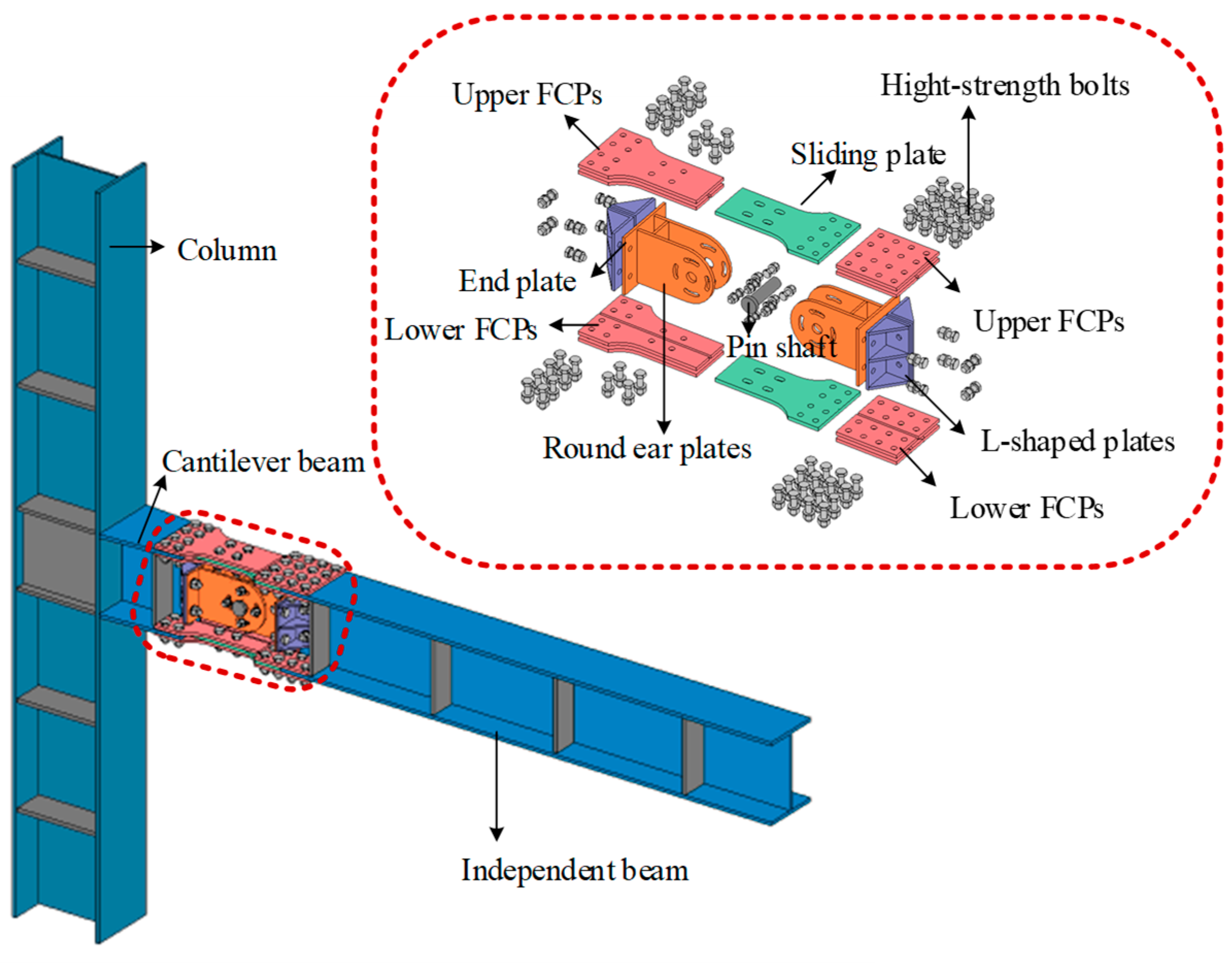
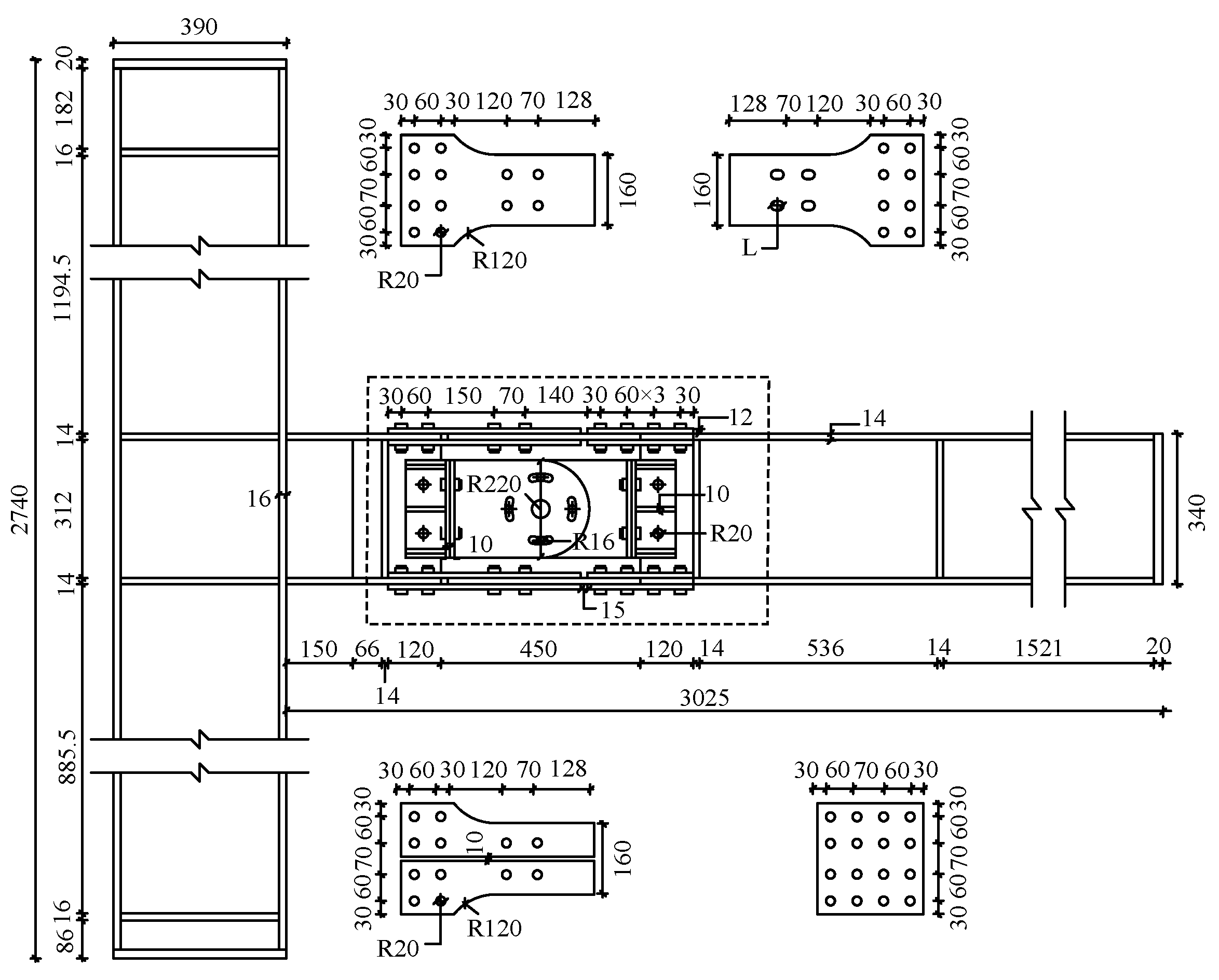
2.1. The Tested Specimens

Pseudo-static tests were conducted to investigate the mechanical behavior of the beam–column joint with the load bearing-energy dissipation connection (BCJ-BEDC). A total of four BCJ-BEDCs were manufactured, and the column and beam were determined based on the principle of “strong column–weak beam”. HM 400 × 300 × 10 × 16 and HM 350 × 250 × 10 × 14 were adopted for the beam and column members for all tested specimens. The lengths of the column and beam were 2740 mm and 3025 mm, while the effective lengths of the column and beam were 3000 mm. The lengths of the cantilever beam and the ordinary beam were 350 mm and 2200 mm, respectively. The design parameters included the slip length and the bolt distance, and the details of the load bearing-energy dissipation connection are tabulated in Table 1. Figure 2 demonstrates the detailed configurations for the proposed BCJ-BEDC.
The sliding steel fuse is made of Q235B steel, while the other constitutive members of the tested specimens are made of Q345 steel. For the load bearing-energy dissipation connection region, high-strength bolts of Grade 10.9 with a diameter of 22 mm were used for the flange bolted connections, and high-strength bolts of Grade 10.9 with a diameter of 18 mm were for the web bolted connection. The material properties of the steel member were obtained through coupon test according to GB/T228.1 2010 [30], including the yield strength fy, the ultimate strength fu, and the yield strain εy. Table 2 lists the results of the material property test.

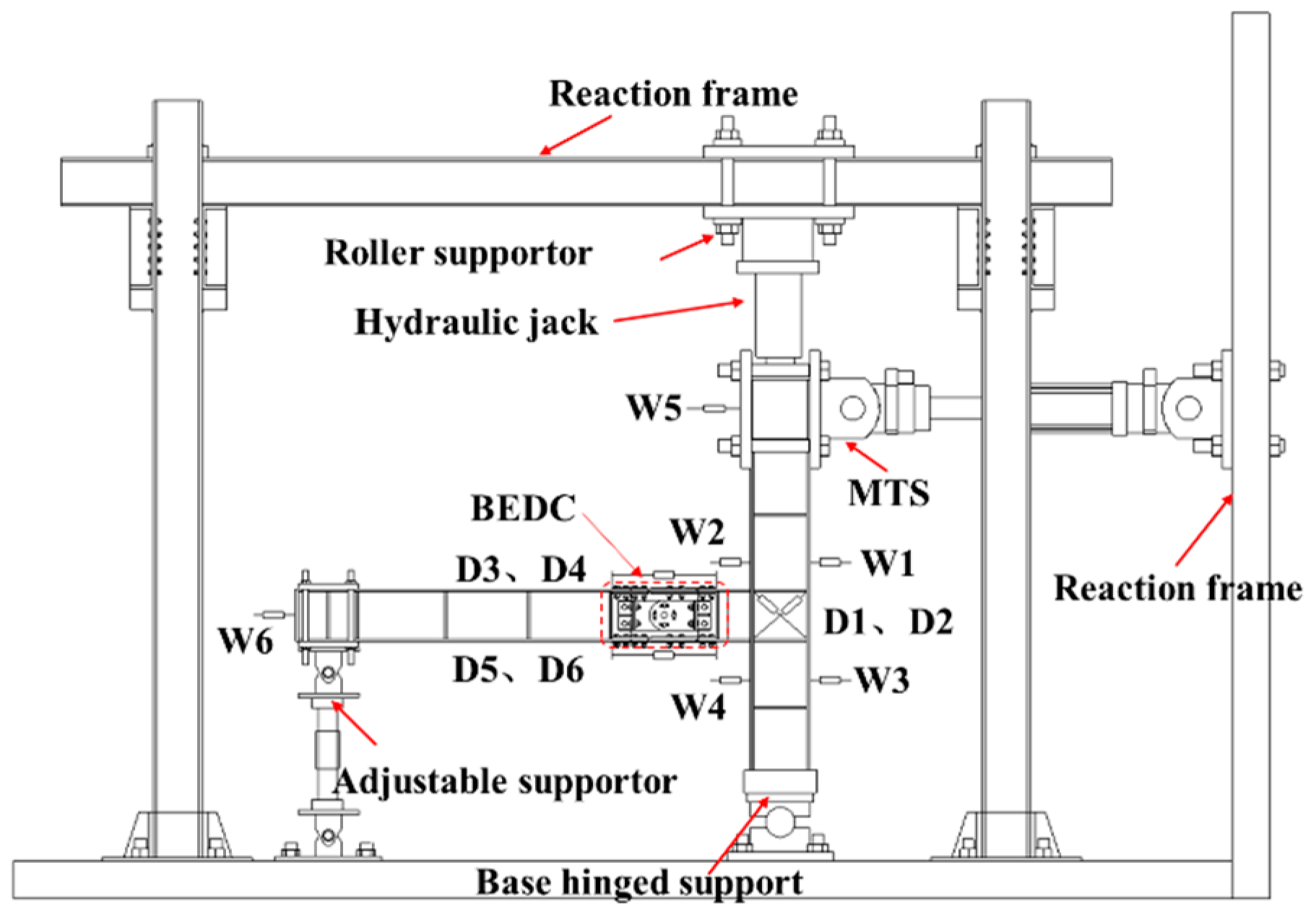
2.2. The Test Scheme

Figure 3 exhibits the test set-up for the BCJ-BEDC, from which it was seen that a hinged support was adopted at the column base, while an adjustable roller support was set at the beam end. The column was connected to a hydraulic jack at the column top, which was used to apply the vertical load, and the axial compression ratio was set as 0.3. The lateral cyclic load was applied by a 500 kN MTS system at the upper column. A preload test was conducted first to check whether all instruments worked normally. Figure 4 shows the loading protocol, which was determined according to AISC seismic provisions [31]. At the initial loading stage, each displacement level was repeated, and then each displacement load level was repeated 3 times. When the bearing capacity decreased to less than 85% of the peak load due to serious damage or the target drift was approached, the test was stopped.
The arrangement of the measurement instruments is also provided in Figure 3. Five displacement meters (W1~W5) were arranged along the column length to record the lateral deformation, and D1~D2 were placed in the joint core to measure the shear deformation. D3~D6 were installed at the upper and lower flange segments to record the relative movement between the sliding steel fuse and FCPs, thereby reflecting the rotation behavior at the connecting region.

3. Results and Discussion

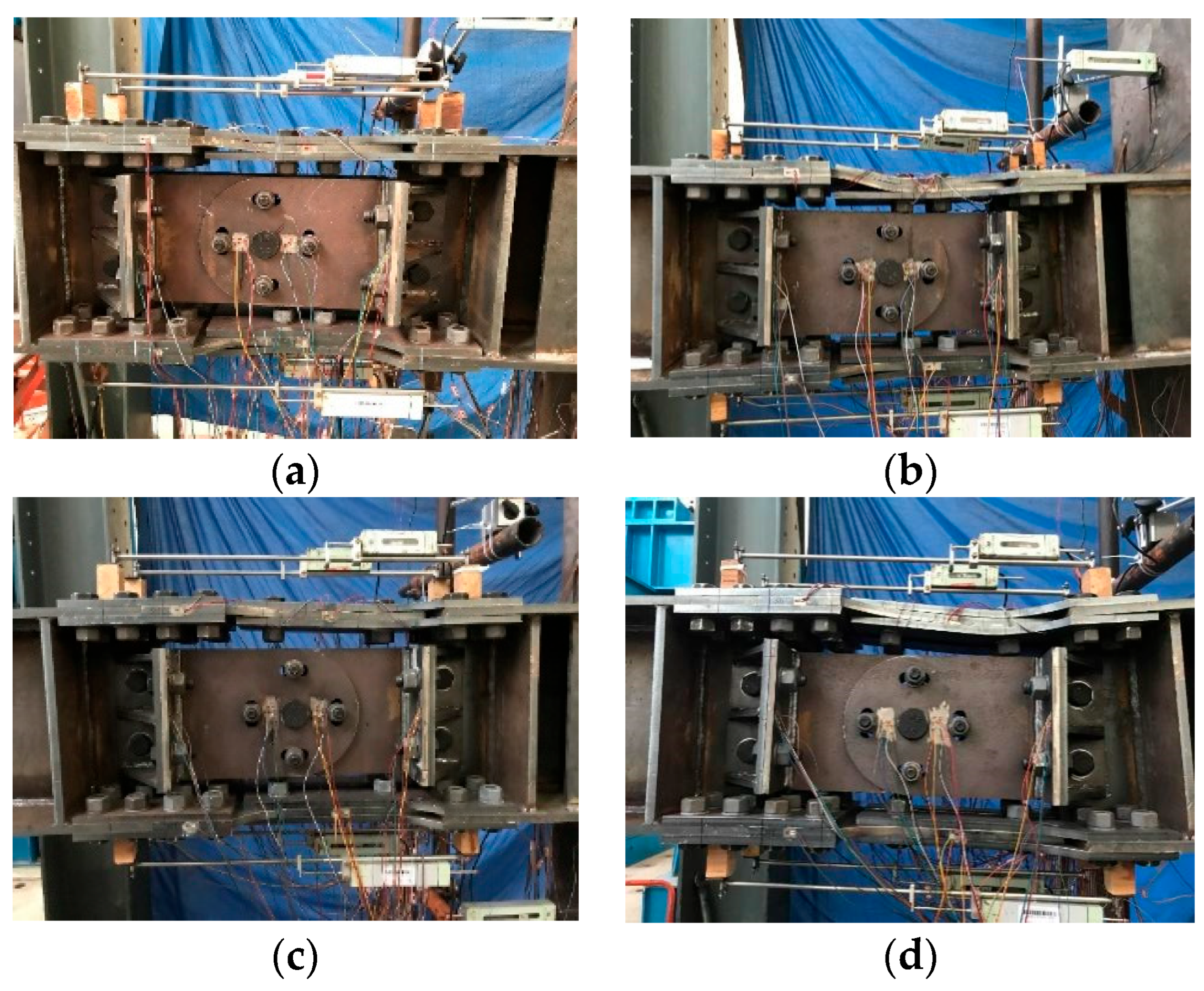
3.1. The Test Phenomena

No obvious phenomena were found at the initial loading, and all members remained elastic. When the loading displacement reached 20 mm, a noise caused by the friction mechanism was slightly heard. Then, the frictional movement between the sliding steel fuses and the FCPs was activated, and the relative movement became more and more apparent with loading increasing, accompanied by a noisy sound. In addition, the global flexural deformation of the load bearing-energy dissipation connection was evident during the slipping stage, while the bearing resistance developed slowly. At the displacement of 60 mm, it was found that the development of the relative movements in BCJ-BEDC2 and BCJ-BEDC4 was slowed down, while the bearing capacity was enhanced quickly. It was deduced that the bolt collided with the edge of the bolt holes and the bolt bearing was activated. For the other BCJ-BEDC specimens, the occurrence of the bolt bearing was induced under a relatively larger displacement of 80 mm, due to a large slip length. Warping deformation was found in the upper FCPs with load increasing. At the bolt bearing stage, the flexural deformation of the BEDC was more evident, and compared with BCJ-BEDC1, the deformation at the connection region of BCJ-BEDC2 and BCJ-BEDC4 was more serious, since the stress development was more significant with a small slip length.
When the loading displacement exceeded 100 mm, the deformation in the flange segment was obvious, especially in the upper flange segment. The strain in the sliding steel fuse exceeded the yield strength and the plastic deformation was serious due to the extrusion by bolts. When the loading displacement approached 120 mm, the BCJ-BEDCs generally remained in stable condition, while the deformation was serious. No obvious performance degradation was found, and the damage was mainly concentrated in the connection region. The test was stopped to avoid unexpected collapse and the drift had exceeded 1/30, far beyond the drift limit required for rare earthquakes. Figure 5 illustrates the failure modes for tested BCJ-BEDCs.

3.2. The Test Results

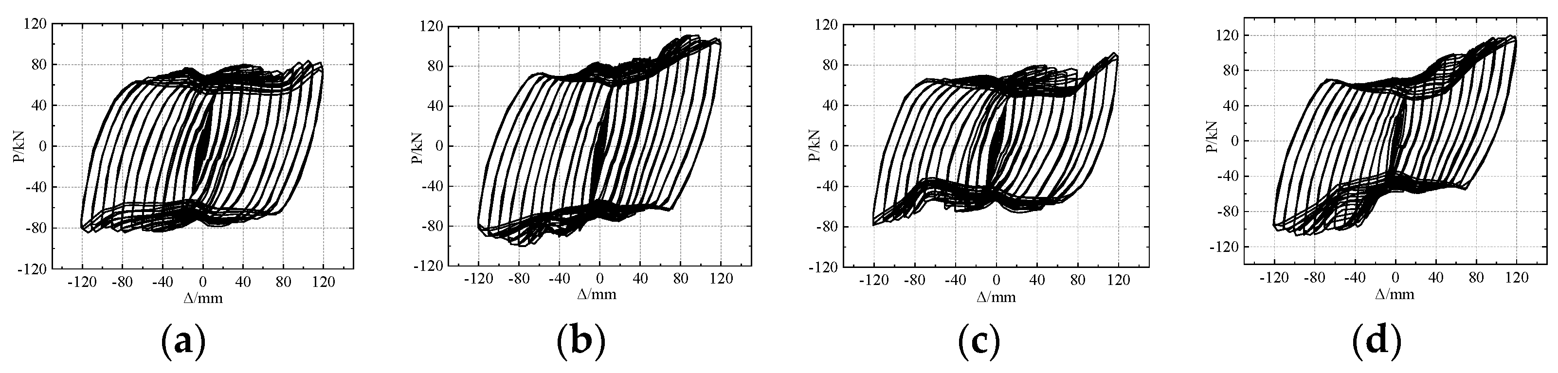
3.2.1. Hysteresis Curves

Figure 6 illustrates the load–deformation hysteresis curves for the tested BCJ-BEDCs. As shown, all the BCJ-BEDCs developed stable mechanical behavior with a plumped hysteresis loop, indicating that the proposed BCJ-BEDC had favorable energy dissipation behavior. Initially, the load linearly increased with the displacement increasing, and the hysteresis loop was small. When the slipping behavior occurred, the load barely developed and a platform segment was found in the hysteresis curves. During the slipping stage, the load was a bit reduced with the load cycles increasing, and it was caused by the loss of bolt pretension and the friction coefficient under repeated loads. The load was enhanced at a later loading stage when the collision between the bolt and the sliding steel fuse occurred. The difference between the comparison groups of BCJ-BEDC1 and BCJ-BEDC2 lied in the slip length, and it could be noted that the load–deformation behavior was different. BCJ-BEDC3 also differed from BCJ-BEDC4 in the slip length. By analysis, the development of the load deformation of the BCJ-BEDC was highly similar if with the same slip length. The maximum load corresponding to the termination of the test for BCJ-BEDC was higher if with a small slip length. The bolt-bearing mechanism helps to improve the bearing capacity, while the generation of the bolt-bearing mechanism was affected by the slip length.
Compared with Figure 6a, the decrease in the load at the slipping stage was greater for the curves in Figure 6c, implying that a large bolt distance imposed an adverse effect on the slipping behavior. The comparison between the curves in Figure 6b,d also came to a similar conclusion. Moreover, a larger bolt distance could lead to a higher bearing capacity, and it was because the damage concentration was more serious if the bolt was arranged closely. However, the bolt distance rarely influenced the hysteresis characteristics of the BCJ-BEDC generally.

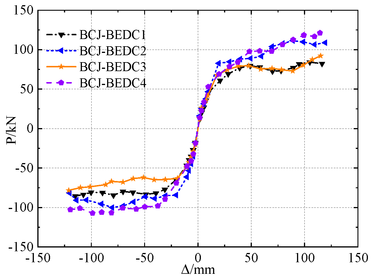
3.2.2. Skeleton Curves

Figure 7 gives the load–deformation skeleton curves for the tested BCJ-BEDCs, exhibiting in an S-shaped manner. The load increased quickly at the beginning of loading, and developed in a linear manner. The development of curves started to differ at the displacement of approximately 20 mm, when the slip was about to occur. It was also found that the skeleton curves for BCJ-BEDC with the same slip length were consistent, which again reflected that the development of the load–deformation behavior was mainly affected by the slip length. The bearing capacity of BCJ-BEDC with a small slip length was higher since the bolt bearing occurred at a relatively smaller displacement, leading to better stress development. The skeleton curves for BCJ-BEDC1 and BCJ-BEDC3 experienced a degradation in load when displacement ranged from 50 mm to 80 mm, corresponding to the slipping stage, due to the loss of friction between the sliding steel fuse and the FCPs.

3.2.3. Primary Performance Results

Table 3 provides the result of primary mechanical indices for tested specimens. It includes the yield displacement Δy, the yield load Py, the ultimate displacement Δu, the peak load Pmax, and the ductility μ. The yield displacement Δy is calculated from the skeleton curve according to Ref. [32], and the displacement at the termination of the test was set as the ultimate displacement since no obvious degradation in strength occurred. The ductility is defined as the ratio between the ultimate displacement and the yield displacement ( μ = Δ u Δ y ).
As outlined in Table 3, the BCJ-BEDC could develop desirable bearing capacity and good ductile behavior. The change in the slip length did not greatly affect the ductile behavior, while the increase in the bolt distance reduced the ductility. A shorter slip length could lead to a higher bearing capacity and the larger bolt distance was also beneficial to the bearing capacity. With a shorter slip length, the bearing action was activated at the smaller deformation level, leading to better stress development in the sliding steel fuse. A larger bolt distance helped to avoid a serious stress concentration in the sliding steel fuse, thereby improving the stress behavior.

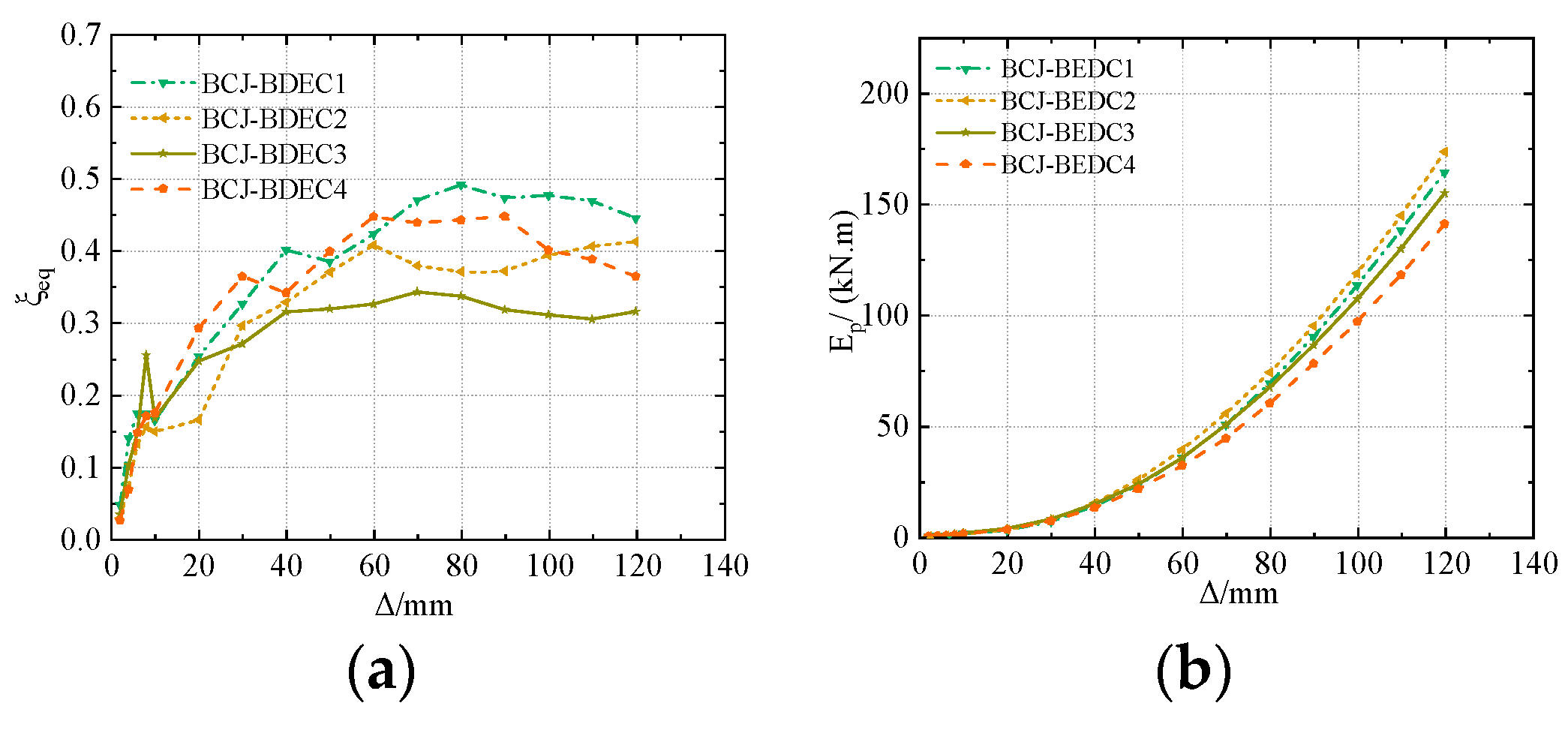
3.2.4. Energy Dissipation

To evaluate the energy dissipation behavior, the equivalent damping ratio (ξeq) and the accumulative energy consumption (Ep) were adopted. The equivalent damping ratio (ξeq) is expressed by Equation (1), and the involved parameter could be calculated according to Figure 8, where SABCD is the area enclosed by the hysteresis loop, while SΔOBE and SΔODF are the area surrounded by triangles. The accumulative energy consumption (Ep) is the sum of the energy dissipation with the displacement increasing.
ξ eq = 1 2 π S ABCD S Δ OBE + S Δ ODF
Figure 9a presents the results of the equivalent damping ratio (ξeq) and Figure 9b illustrates the results of energy consumption under different displacement levels. At the initial loading, the equivalent damping ratio and the accumulative energy consumption were small since the BCJ-BEDC was almost in an elastic state. With loading increasing, slipping behavior occurred, leading to a quick increase in the equivalent damping ratio. However, the equivalent damping ratio was reduced under larger displacement due to the improvement in the bearing capacity caused by the bearing behavior. Generally, the equivalent damping ratio was larger than 0.3 at the later loading stage, indicating that the proposed BCJ-BEDC had favorable energy dissipation behavior. In addition, the energy dissipation was increased greatly with the displacement increasing, also reflecting the good energy dissipation behavior of the BCJ-BEDC.

4. Finite Element Analysis

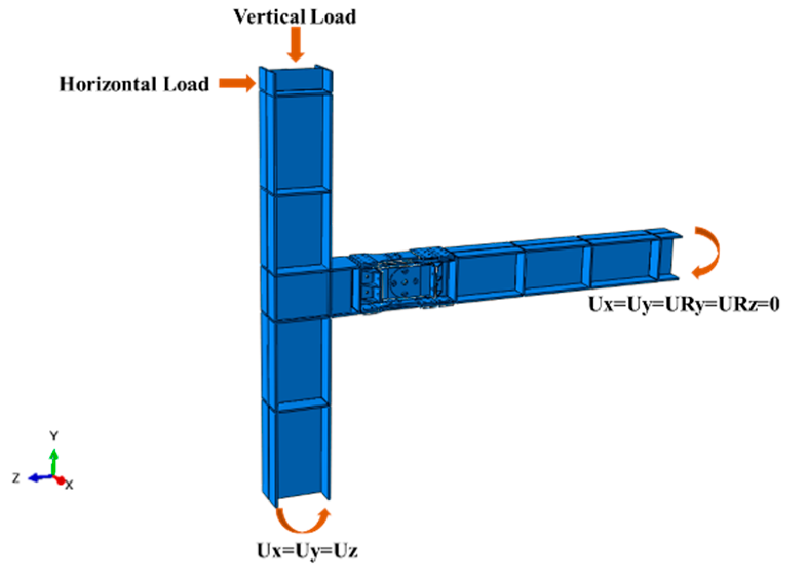
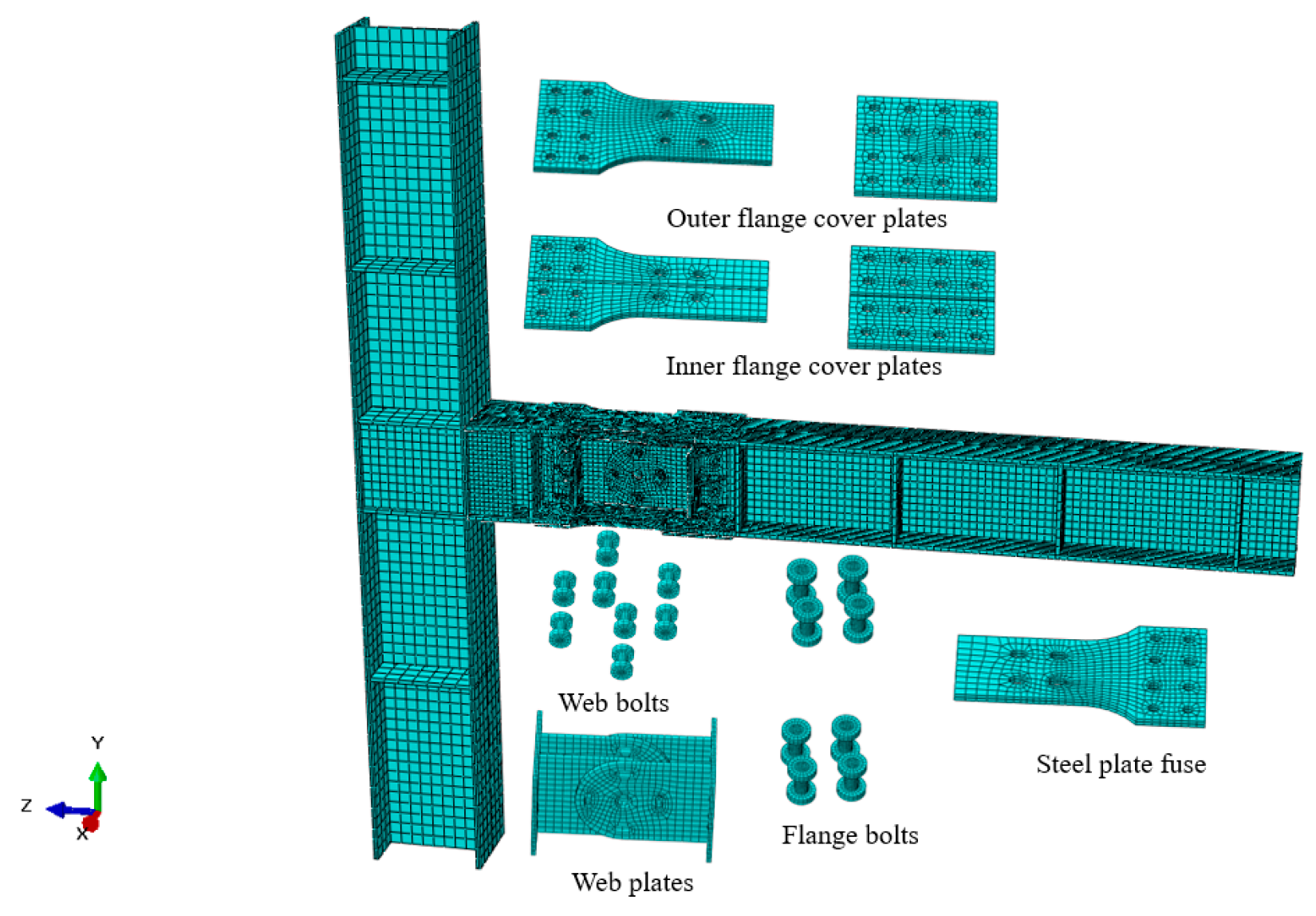
4.1. Finite Element Model

The development of finite element models (FEMs) is an efficient complementary investigation for a test study, with less cost and time consumption. To further investigate the mechanical mechanism of the beam-to-column joint with the bearing-energy dissipation (BCJ-BEDC) and the influence of different parameters, the FEM of the BCJ-BEDC was built using ABAQUS software (version 6.14-1), and the accuracy of the modeling was validated.
In the FEM, all constitutive components were built with 3D solid elements, the sliding steel fuse was made of Q235B steel, and the other components were made of Q345 steel. The material properties of the steel referred to the coupon test result, as listed in Table 2, and a kinematic hardening model with the von Mises yield criterion was adopted to reflect the stress–strain behavior. Furthermore, the bilinear kinematic hardening model was also used for high-strength bolts, to reflect the constitutive relationship, with Young’s modulus, the yield strength and ultimate strength of 206,000 MPa, 960 MPa and 1196 MPa, respectively. The Poisson’s for steel and high-strength bolt was taken as 0.3.
As presented in Figure 10, the translation motion at the column base was restricted to mimic the hinged support. From beam, only the translation motion in the z-direction, and rotational motion in the z-y plane were free to reflect the boundary condition at the beam end. The vertical load was applied at the top surface of the column and the horizontal load was applied at the upper column, with the same loading protocol to the test. As for the interactions between different components, the bolted connections between the BEDC and the beams were imitated with tie interactions for simplicity since the slipping was not allowed, thereby improving simulation efficiency. However, the frictional interaction between the members in the BEDC was simulated through contact pairs to establish surface-to-surface contact. In the surface-to-surface contact, the properties of the normal behavior and tangent behavior were important. For the established FEA, the hard contact, and the Coulomb friction model were used to mimic the normal behavior and tangent behavior. According to the recommendation from GB 50017-2017 [33], the friction coefficient of 0.4 was preliminarily adopted for the tangent behavior since no surface treatment was performed. The bolt preload (190 kN for M20 and 155 kN for M16) was applied through the bolt load. To achieve better convergence, a small preload was applied first to establish a stable contact, then the preload was increased to the designed bolt pretension, and finally, the bolt length was fixed to achieve the designed bolt pretension.
For the meshing details, the C3D8R elements (eight-node linear brick element with reduced integration and hourglass control) were used for the column, beams, sliding steel fuses, and bolts. For the flange and web of the framing component, two elements were employed in the thickness direction, while for the steel plate dampers, three elements were employed for the flange and web of beam and column in the thickness direction. Moreover, a finer mesh size of roughly 30 mm was employed for the BEDC and the connecting region in beams, while a coarse mesh size of roughly 100 mm was employed for other members, as shown in Figure 11.

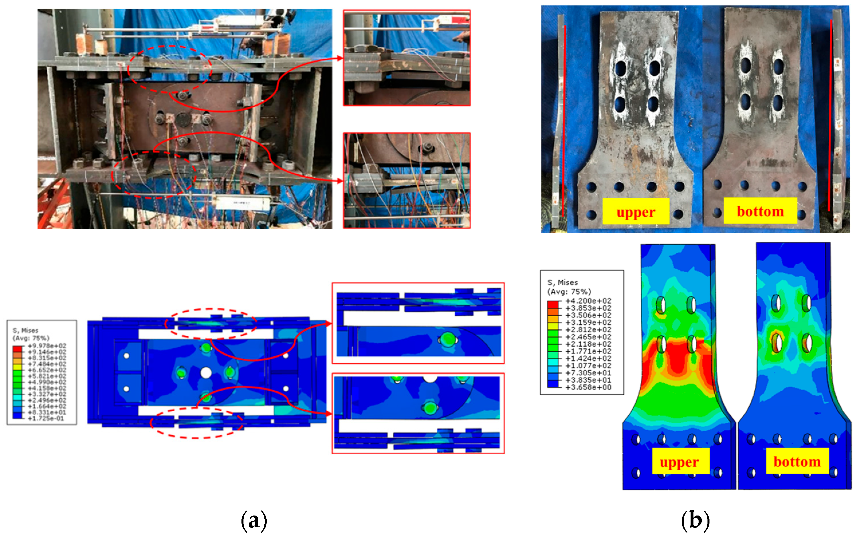
4.2. Model Validation

The failure process and the hysteresis behavior of the developed FE models for tested specimens were similar, and then BCJ-BEDC1 was taken as an example to illustrate the comparisons between the test and the simulation.
Figure 12 demonstrates the failure modes obtained numerically. The residual flexural deformation was found in the segment of the BEDC and the stress developed in the BEDC was more serious than the framing members. Furthermore, the plastic behavior of the BEDC was concentrated in the sliding steel fuse. The comparison between the test results implies that both the overall failure mode and local failure mode obtained from the simulation matched well with the test result, and FE modeling could be used to reflect the failure process of the beam–column joint with BEDC under cyclic loading.
Figure 13 illustrates the comparison of load-displacement hysteretic curves between the test results and numerical results, for the beam-column joint and the moment-rotation hysteretic curve for the BEDC. As seen, both the global and local hysteresis behavior obtained from the simulation agreed well with the test results. The development of the load–deformation characteristics was linear initially, and then the development of the load was slowed down due to the occurrence of slipping behavior. An obvious increase in the bearing capacity was observed at the later loading stage, caused by the bearing action between the bolts and the sliding steel fuse.

4.3. Parametric Study

To further investigate the influence of different parameters on the mechanical behavior of the beam–column joint with the BEDC, a parametric study was conducted. The performance including the load–displacement curve, the accumulative energy dissipation, and the equivalent damping ratio is discussed.

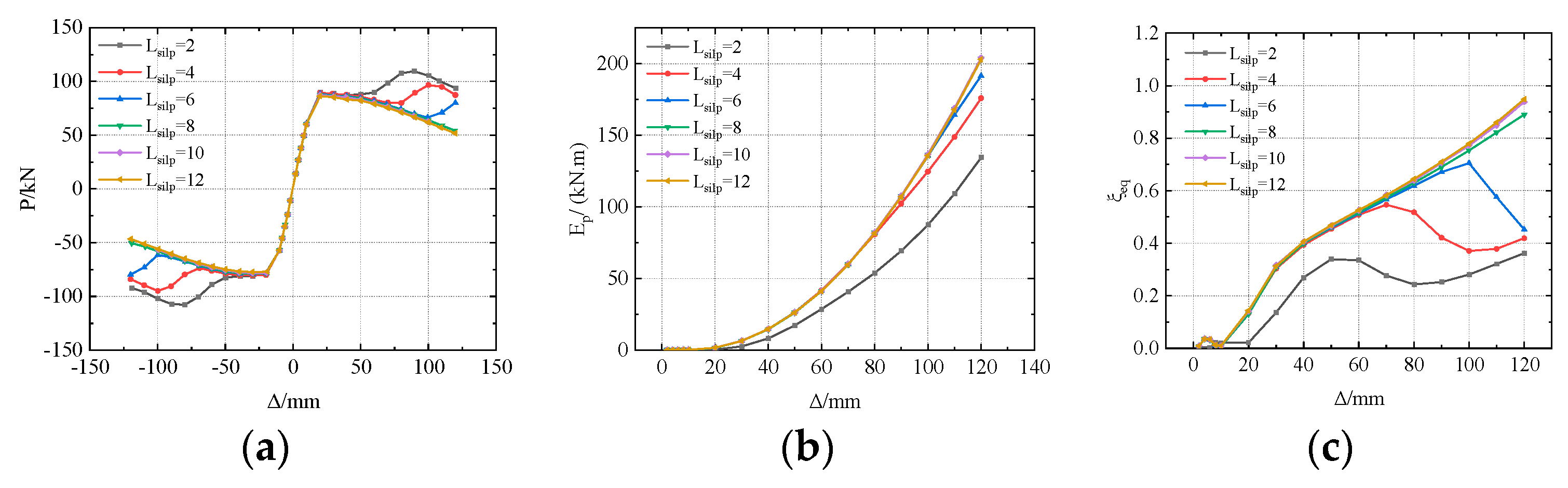
4.3.1. The Slip Length

Figure 14 gives the results of the primary mechanical behavior of the beam–column joint with the BEDC considering the influence of the slip length. In Figure 14a, the slip length barely affected the initial stiffness, and the curves overlapped. With load increasing, the BCJ-BEDC generated an increase in the load when the slip length was less than 6 mm, caused by the bolts bearing with the sliding steel fuse. With a shorter slip length, bearing action was induced under a relatively smaller displacement and led to a more obvious enhancement in the bearing capacity. Bearing action did not occur with a slip length longer than 8 mm, and a decrease in the bearing capacity was found due to the loss of the friction coefficient and bolt pretension under cyclic loading. From Figure 14b,c, the accumulative energy dissipation and the equivalent damping ratio were improved with the increase in the slip length. However, the advantage of the slip length on the energy dissipation behavior was reduced with an excessively longer slip length.

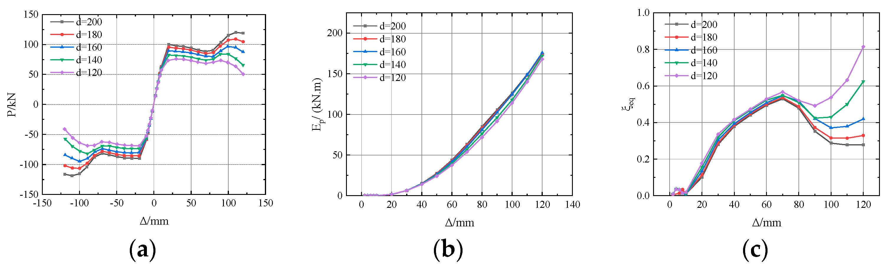
4.3.2. The Width of the Sliding Steel Fuse

Given that the bearing behavior was mainly influenced by the stress behavior of the sliding steel fuse, the influence of the width of the sliding steel fuse was investigated. Figure 15 presents the results of the primary mechanical behavior of the BCJ-BEDC considering the influence of the width of the sliding steel fuse. It was seen that the change in the width of the sliding steel fuse did not affect the two-stage load–deformation characteristics of the BCJ-BEDC since all the numerical models had the same slip length, as in Figure 15a. Differences were found after the slipping behavior was activated. The deformation of the BEDC with a smaller width of the sliding steel fuse was more serious, and a premature loss in the friction load was induced. Once the bearing action occurred, the bearing capacity of the BEDC was primarily determined by the mechanical behavior of the sliding steel fuse. The bearing action was beneficial for the improvement of the bearing capacity, and a wider sliding steel fuse could result in a higher bearing capacity. Furthermore, the degradation behavior of the BCJ-BEDC with a wider sliding steel fuse was alleviated when the stress concentration was reduced. In Figure 15b,c, the influence of the width of the sliding steel fuse on the accumulative energy dissipation was not significant, while the equivalent damping ratio corresponding to the bearing stage was affected by the width of the sliding steel fuse. The BCJ-BEDC with a wider sliding steel fuse developed a relatively smaller equivalent damping ratio due to a more significant enhancement in the bearing capacity.

4.4. Mechanical Mechanism Analysis

With references to the skeleton curves obtained from the test and parametric study, it was considered that the development of the load–deformation behavior experienced four stages, as demonstrated in Figure 16. By analysis, the initiation of the slipping behavior (Point A), the initiation of bearing behavior (Point B), and the initiation of degradation in performance (Point C) are the feature points during the whole loading process. From the initial loading to point A, the BCJ-BEDC was elastic, and the skeleton curve was linear. From point A to point B, the BCJ-BEDC was in the slipping stage, where the load did not change greatly with the deformation increasing. After Point B, the BCJ-BEDC entered into the bearing stage, and the bearing capacity was increased more quickly until reaching the peak point (Point C). Afterward, degradation in the performance occurred.
Figure 17 illustrates the stress conditions and damage development when the BCJ-BEDC reached Point A. When the BEDC started to slip, the stress in the beam and column was less than the yielding strength, with a maximum Mises stress of 231.1 MPa. The stress in the BEDC was close to the yield strength and the maximum stress was found in the sliding steel fuse.
Figure 18 illustrates the stress condition and the damage development when loaded to Point B. The bolts collided with the edge of the slotted hole in the sliding steel fuses, and the stress in the framing components increased to 264.54 MPa, indicating that the stress development in the slipping stage was not significant. It was also concluded that the slipping behavior of the sliding steel fuse improved the stress development of the framing component. As for the BEDC, the maximum stress developed larger than the yield strength (284 MPa), which was generated around the bolting region of the sliding steel fuse (shown in Figure 18c). Compared with Figure 17c and Figure 18c, it was known that the sliding steel fuses experienced obvious stress development, which might be caused by the large flexure deformation. The stress in the FCPs was also more serious, while the plastic behavior was primarily concentrated in the sliding steel fuse.
At the bearing stage, the bearing capacity was enhanced, and the maximum Mises stress in the framing approached 361.94 MPa, which was still less than the yield strength of 391 MPa. The stress condition and the damage development are provided in Figure 19. From Figure 19c, the stress development in the BEDC was more adequate, with the yielded part expanding to a larger region. The sliding steel fuse developed an ultimate stress of 391 MPa due to the constant bolt-bearing action at Point C. The stress development in the sliding steel fuse was more serious than the FCPs, and slight yielding behavior was found in the FCPs. By analysis, the plastic behavior was concentrated in the BEDC while the framing components remained in good condition, indicating that the use of the BEDC could achieve damage concentration.

5. Conclusions

This paper presents a novel beam–column joint with a load bearing-energy dissipation connection, and investigates the hysteresis behavior through cyclic tests. The mechanical mechanism under cyclic loading was also discussed through the numerical study. Some main conclusions are summarized as follows:
(1)
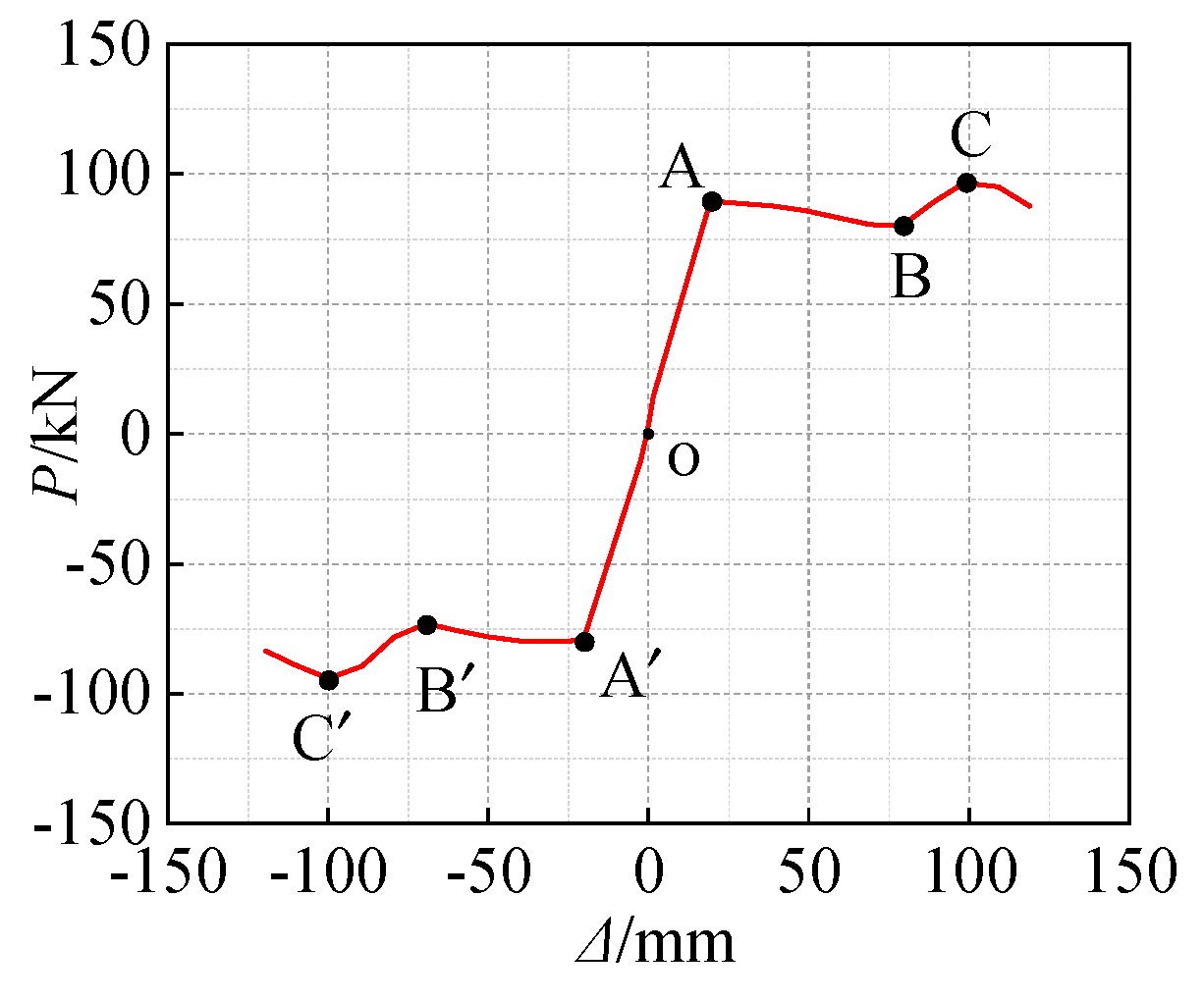
The beam–column joint with the load bearing-energy dissipation connection could develop two-stage load–deformation characteristics, featuring a friction mechanism and bearing mechanism. The hysteresis behavior of the BCJ-BEDC was stable without obvious degradation, and the maximum drift could exceed 1/30.
(2)
The friction mechanism caused by the slipping behavior could improve the stress development of the framing components, and it also improved the energy dissipation behavior. The bearing mechanism was conducive to the bearing capacity, while it resulted in more serious development of the plastic behavior of the BEDC.
(3)
The slip length greatly influenced the load–deformation behavior of the BCJ-BEDC. A shorter slip length led to a higher bearing capacity, while it might reduce the energy dissipation capacity. The bolt distance primarily affected the ductility and the bearing capacity, which were improved through a larger bolt distance. The width of the sliding steel fuse primarily affected the bearing behavior and the degradation behavior.
(4)
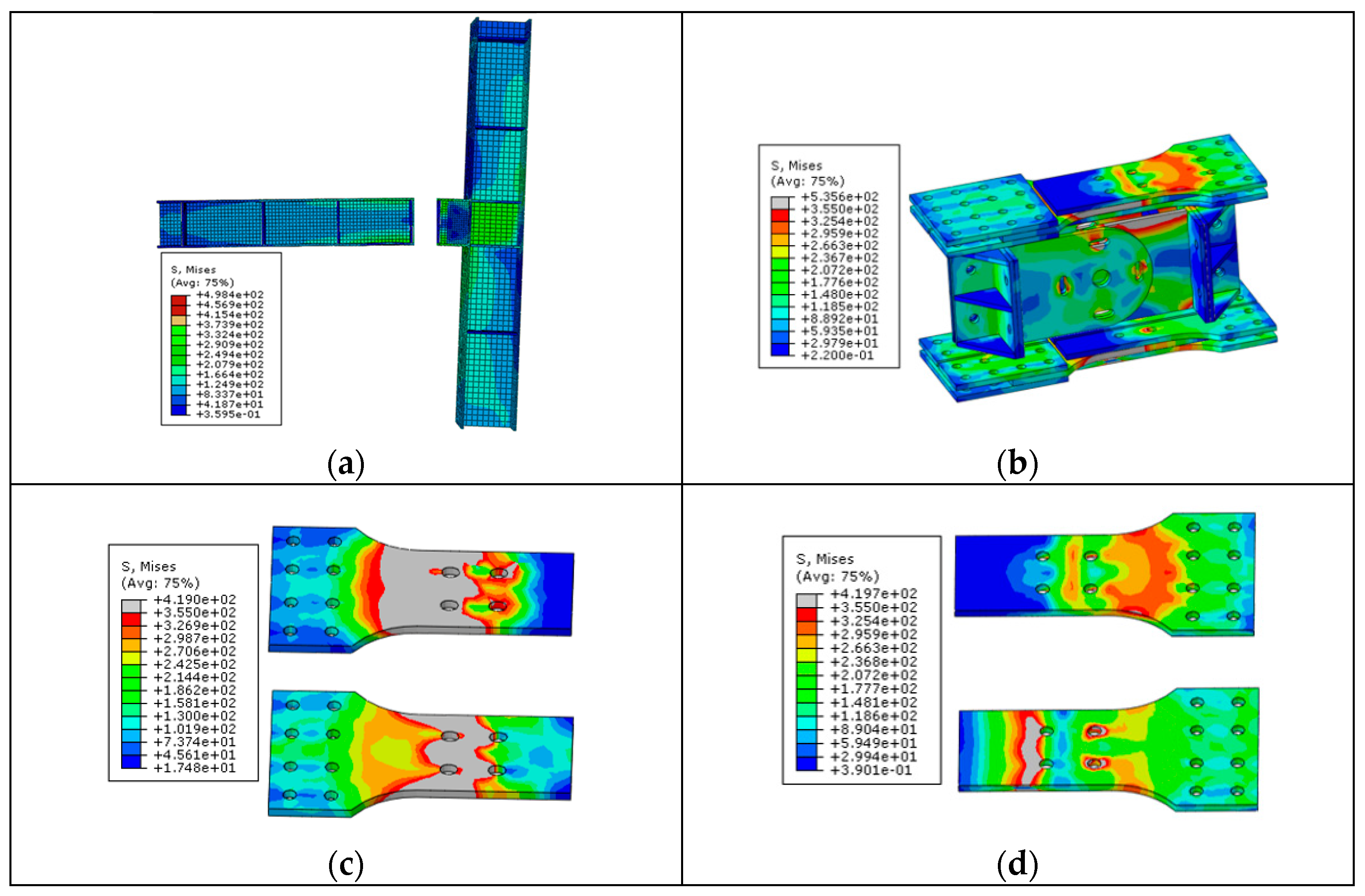
The stress development of the BEDC was more serious than the framing components, and the Mises stress in the framing component did not exceed the yield strength during the whole loading process. The stress of the BEDC developed more quickly in the bearing stage, and the stress development was more adequate. The plastic behavior of the BCJ-BEDC was concentrated on the BEDC, especially on the sliding steel fuse.

Author Contributions

Conceptualization, X.G.; Methodology, S.L.; Software, R.L. and X.C.; Validation, S.L. and X.C.; Investigation, R.L. and X.C.; Writing—original draft, R.L.; Writing—review and editing, X.G. and R.L.; Funding acquisition, X.G. All authors have read and agreed to the published version of the manuscript.

Funding

This research project was supported by “The research project of State Grid Fujian Economic Research Institute (Study on the application of high–performance concrete building materials for prefabricated substations in coastal areas, Contract Number: SGFJJY00BDJS2400038)”.

Data Availability Statement

The data presented in this study are available upon request from the corresponding author.

Acknowledgments

The work performed by Qiulan Lai is highly appreciated, including the contributions to the software and investigation.

Conflicts of Interest

Authors Xian Gao, Shaoyuan Lin and Xilong Chen were employed by the company State Grid Fujian Electric Power Co., Ltd. The remaining authors declare that the research was conducted in the absence of any commercial or financial relationships that could be construed as a potential conflict of interest.

References

  1. Dubina, D.; Stratan, A. Behaviour of welded connections of moment resisting frames beam-to-column joints. Eng. Struct. 2002, 24, 1431–1440. [Google Scholar] [CrossRef]
  2. Abdoh, D. Three-dimensional peridynamic modeling of deformations and fractures in steel beam-column welded connections. Eng. Fail. Anal. 2024, 160, 108155. [Google Scholar] [CrossRef]
  3. Vacev, T.; Paunović, S.; Nešović, I.; Zorić, A.; Milić, M. Plasticization conditions and strength of a welded beam-to-column connection in case of various detailing. Eng. Struct. 2018, 165, 11–26. [Google Scholar] [CrossRef]
  4. Lu, L.W.; Ricles, J.M.; Mao, C.; Fisher, J.W. Critical issues in achieving ductile behaviour of welded moment connections. J. Constr. Steel Res. 2000, 55, 325–341. [Google Scholar] [CrossRef]
  5. Jannesari, Z.; Tasnimi, A.A. Investigating seismic behavior of a modified widened flange beam-column connection in SMRF utilizing experimental, numerical and hybrid simulation. J. Constr. Steel Res. 2023, 207, 107971. [Google Scholar] [CrossRef]
  6. Sofias, C.; Pachoumis, D. Assessment of reduced beam section (RBS) moment connections subjected to cyclic loading. J. Constr. Steel Res. 2020, 171, 106151. [Google Scholar] [CrossRef]
  7. Sophianopoulos, D.S.; Deri, A.E. Steel beam-to-column RBS connections with European profiles: I. Static optimization. J. Constr. Steel Res. 2017, 139, 101–109. [Google Scholar] [CrossRef]
  8. Horton, T.A.; Hajirasouliha, I.; Davison, B.; Ozdemir, Z. More efficient design of reduced beam sections (RBS) for maximum seismic per-formance. J. Constr. Steel Res. 2021, 183, 106728. [Google Scholar] [CrossRef]
  9. Ohsaki, M.; Tagawa, H.; Pan, P. Shape optimization of reduced beam section under cyclic loads. J. Constr. Steel Res. 2009, 65, 1511–1519. [Google Scholar] [CrossRef]
  10. Atashzaban, A.; Hajirasouliha, I.; Jazany, R.A.; Izadinia, M. Optimum drilled flange moment resisting connections for seismic regions. J. Constr. Steel Res. 2015, 112, 325–338. [Google Scholar] [CrossRef]
  11. Shi, G.; Chen, X.; Wang, D. Experimental study of ultra-large capacity end-plate joints. J. Constr. Steel Res. 2017, 128, 354–361. [Google Scholar] [CrossRef]
  12. Lee, C.H.; Jung, J.H.; Oh, M.H.; Koo, E.S. Cyclic seismic testing of steel moment connections reinforced with welded straight haunch. Eng. Struct. 2003, 25, 1743–1753. [Google Scholar] [CrossRef]
  13. Tartaglia, R.; D’Aniello, M.; Zimbru, M.; Landolfo, R. Finite element simulations on the ultimate response of extended stiffened end-plate joints. Steel Compos. Struct. 2018, 27, 727–745. [Google Scholar]
  14. Zkılıç, Y.O. Cyclic and monotonic performance of unstiffened extended end-plate connections having thin end-plates and large-bolts. Eng. Struct. 2023, 281, 115794. [Google Scholar] [CrossRef]
  15. Munkhunur, T.; Hiroshi Tagawa, H.; Xingchen Chen, X.C. Steel rigid beam-to-column connections strengthened by buck-ling-restrained knee braces using round steel core bar dampers. Eng. Struct. 2022, 250, 113431. [Google Scholar] [CrossRef]
  16. Yu, Q.S.; Uang, C.M.; Gross, J. Seismic Rehabilitation Design of Steel Moment Connection with Welded Haunch. J. Struct. Eng. 2000, 126, 69–78. [Google Scholar] [CrossRef]
  17. Wang, M.; Ke, X.G. Seismic design of widening flange connection with fuses based on energy dissipation. J. Construc-Tional Steel Res. 2020, 170, 106076. [Google Scholar] [CrossRef]
  18. GB 50011-2010; Code for Seismic Design of Buildings. National Standard of the People’s Republic of China (NSPRC): Beijing, China, 2008.
  19. Hamburger, R.O. Prequalified connections for special and intermediate steel moment frames for seismic applications, ANSI/AISC 358-05. In Proceedings of the Structures Congress 2006, St Louis, MO, USA, 18–21 May 2006. [Google Scholar]
  20. Liu, X.C.; Wang, Y.; Cui, X.X.; Yu, C.; Bai, Z.X. Seismic performance of bolted beam-to-column connection with rib-stiffened splicing plate. J. Constr. Steel Res. 2020, 174, 106300. [Google Scholar] [CrossRef]
  21. Mou, B.; Liu, Y.; Wei, P.; Zhao, F.; Chenglong, W.; Ning, N. Numerical investigation and design method of bolted beam-column joint panel with eccentricity in beam depths. J. Constr. Steel Res. 2021, 180, 106568. [Google Scholar] [CrossRef]
  22. Zhang, A.L.; Qiu, P.; Guo, K.; Jiang, Z. Experimental study of earthquake-resilient end-plate type prefabricated steel frame beam-column joint. J. Constr. Steel Res. 2020, 166, 105927. [Google Scholar] [CrossRef]
  23. Chung, Y.L.; Chuang, C.H. Performance recovery of locally buckled reduced beam section connections by attaching buck-ling-restrained components. J. Constr. Steel Res. 2023, 210, 108122. [Google Scholar] [CrossRef]
  24. Xu, Y.; Su, Y.; Shang, Y.; Tian, L.-M. Seismic performance of earthquake-resilient prefabricated corrugated web beam-column connection with buckling-restrained plates. J. Constr. Steel Res. 2022, 194, 107327. [Google Scholar] [CrossRef]
  25. Feng, Y.; Wen, H.; Jiang, Q.; Chong, X. Experimental and numerical investigations of beam-to-column joints with a double-core buck-ling-restrained connector. J. Build. Eng. 2022, 51, 104225. [Google Scholar] [CrossRef]
  26. Liu, C.; Wu, J.; Xie, L. Seismic performance of buckling-restrained reduced beam section connection for steel frames. J. Constr. Steel Res. 2021, 181, 106622. [Google Scholar] [CrossRef]
  27. Lu, Y.; Guo, Z.; Basha, S.H.; Liu, Y. Performance of steel beams with replaceable buckling restrained fuses under cyclic loading. J. Constr. Steel Res. 2022, 194, 107310. [Google Scholar] [CrossRef]
  28. Chen, P.; Pan, J.; Hu, F.; Wang, Z. Experimental investigation on earthquake-resilient steel beam-to-column joints with replaceable buckling-restrained fuses. J. Constr. Steel Res. 2022, 196, 107413. [Google Scholar] [CrossRef]
  29. Chen, P.; Pan, J.; Hu, F.; Wang, Z. Numerical investigation on seismic resilient steel beam-to-column connections with replaceable buckling-restrained fuses. J. Constr. Steel Res. 2022, 199, 107598. [Google Scholar] [CrossRef]
  30. GB/T228.1; Metallic Materials-Tensile Testing at Ambient Temperature. China Standard Press: Beijing, China, 2010.
  31. ANSI/AISC 360-14; Seismic Provisions for Structural Steel Buildings. AISC: Chicago, IL, USA, 2016.
  32. Feng, P.; Qiang, H.L.; Ye, L.P. Discussion and definition on yield points of materials, members and structures. Eng. Mech. 2017, 34, 36–46. (In Chinese) [Google Scholar]
  33. GB 50017-2017; Standard for Design of Steel Structures. China Architecture & Building Press: Beijing, China, 2017.
Figure 1. Configurations of the BCJ-BEDC.
Buildings 14 02424 g001
Figure 2. Geometric configurations of BCJ-BEDC.
Buildings 14 02424 g002
Figure 3. Test set-up.
Buildings 14 02424 g003
Figure 4. Loading protocol.
Buildings 14 02424 g004
Figure 5. Failure modes of tested specimens. (a) BCJ-BEDC1. (b) BCJ-BEDC2. (c) BCJ-BEDC3. (d) BCJ-BEDC4.
Buildings 14 02424 g005
Figure 6. Hysteretic curves of tested specimens. (a) BCJ-BEDC1. (b) BCJ-BEDC2. (c) BCJ-BEDC3. (d) BCJ-BEDC4.
Buildings 14 02424 g006
Figure 7. Skeleton curves of tested specimens.
Buildings 14 02424 g007
Figure 8. Schematic diagram of hysteresis loops.
Buildings 14 02424 g008
Figure 9. (a) The equivalent viscous damping ratio. (b) The accumulative energy consumption.
Buildings 14 02424 g009
Figure 10. Boundary condition.
Buildings 14 02424 g010
Figure 11. Mesh size.
Buildings 14 02424 g011
Figure 12. Comparisons of the failure modes. (a) Failure mode of the BEDC. (b) Failure mode of the sliding steel fuse.
Buildings 14 02424 g012
Figure 13. Comparisons of the hysteresis curves. (a) The P–Δ curve for BCJ-BEDC. (b) The M–φ curve for the BEDC.
Buildings 14 02424 g013
Figure 14. The influence of the slip length on the primary performance indices. (a) The P–Δ curves. (b) The accumulative energy dissipation. (c) The equivalent damping ratio.
Buildings 14 02424 g014
Figure 15. The influence of the width of the sliding steel fuse on the primary performance indices. (a) The P–Δ curves. (b) The accumulative energy dissipation. (c) The equivalent damping ratio.
Buildings 14 02424 g015
Figure 16. The load–deformation characteristics.
Buildings 14 02424 g016
Figure 17. The stress nephogram at point A. (a) Framing components. (b) The BEDC. (c) The sliding steel fuses. (d) The FCPs.
Buildings 14 02424 g017
Figure 18. The stress nephogram at point B. (a) Framing components. (b) The BEDC. (c) The sliding steel fuses. (d) The FCPs.
Buildings 14 02424 g018
Figure 19. The stress nephogram at point C. (a) Framing components. (b) The BEDC. (c) The sliding steel fuses. (d) The FCPs.
Buildings 14 02424 g019
Table 1. Parameters of specimens.
Specimen No.t/mmd/mmLs/mmD/mm
BCJ-BEDC 114160470
BCJ-BEDC 214160270
BCJ-BEDC 3141604128
BCJ-BEDC 4141602128
Note: t and d are the thickness and the width of the sliding steel fuse, respectively. Ls is the slip length, D is the bolt distance.
Table 2. Mechanical properties of test specimens.
MemberGradet/mmfy/MPafu/MPaεy/με
Column flangeQ345163915602519
Beam flange144005612540
Flange cover plate123875542579
Steel plate damperQ235B142843911759
Table 3. Primary mechanical indices of tested specimens.
Specimen No.Δy/mmPy/mmΔu/mmPmax/kNμμ
BCJ-BEDC 139.476.6117.282.22.973.47
−30.5−77.5−121−81.93.97
BCJ-BEDC 244.888.3117.8104.22.633.35
−29.6−85.8−120.3−82.34.06
BCJ-BEDC 351.978.1115.792.12.232.36
−48.6−63.2−121−78.92.49
BCJ-BEDC 458.898.3115.1121.11.962.67
−35.4−96.5−119.5−103.53.38
Disclaimer/Publisher’s Note: The statements, opinions and data contained in all publications are solely those of the individual author(s) and contributor(s) and not of MDPI and/or the editor(s). MDPI and/or the editor(s) disclaim responsibility for any injury to people or property resulting from any ideas, methods, instructions or products referred to in the content.

