Abstract
This study aimed to rigorously evaluate the impact of tuned mass dampers (TMDs) on structural response under seismic excitation. By strategically placing TMDs at various levels within the structures, the research sought to determine their effectiveness in mitigating structural movement. A single-degree-of-freedom (SDOF) system incorporating TMDs was utilized to model structures of 10, 13, and 16 stories, each configured with TMDs at different heights. The structures were subjected to near-fault earthquakes to assess the efficacy of TMDs in reducing structural response. The findings revealed significant enhancements in structural performance when TMDs were optimally positioned. Specifically, a 50% reduction in both acceleration and displacement, alongside a 65% decrease in maximum drift, underscored the effectiveness of TMD deployment. Furthermore, the study demonstrated that distributing multiple TMDs along the height of the structure provided superior drift control. Notably, positioning TMDs within the upper one-third of the structure yielded the most pronounced improvements in acceleration, displacement, and maximum drift. Finally, the research indicates that the strategic incorporation of TMDs can significantly enhance the seismic resilience of structures. The results highlight the substantial benefits of TMDs in optimizing acceleration, displacement, and drift, thereby affirming their critical role in seismic design and retrofitting strategies.
1. Introduction
New devices have been developed and implemented to reduce vibrations in buildings caused by earthquakes and wind. These devices are categorized into three types: passive, semi-active, and active systems.
Passive control devices are systems that do not require an external power source. The forces developed in these devices due to building motions are utilized by the devices themselves. Examples of such devices include base isolation systems and tuned mass dampers (TMDs).
Recent research has extensively focused on tuned mass damper (TMD) systems. A TMD typically consists of a significant mass, a spring, and a viscous damper, and it is used to reduce vibrations induced by gravity forces [1].
The theoretical development of the TMD system dates back to 1928, when Ormondroyd and Den introduced the concept of a dynamic vibration absorber [2].
Research on multiple tuned mass dampers (TMDs) has been conducted to reduce earthquake-induced building motion. This research developed a methodology for designing multiple TMD systems to mitigate building responses. The results indicated that multiple passive TMD systems can achieve motion reductions of 40% to 60% when the building mass is increased by up to 5% [3].
In another study, the optimized parameters for multiple tuned mass dampers (MTMDs) in base-excited damped systems were investigated. The research focused on optimizing the parameters of MTMDs to suppress the dynamic response of a base-excited structure in a specific mode. The results demonstrated that an optimally designed MTMD system is more effective than a single optimized TMD system for the same mass. As the number of TMDs increases, the optimum damping ratio decreases while the frequency bandwidth increases moderately [1,4,5].
Other studies compared the control performances of three types of dampers for suppressing extreme building vibrations. The conclusion drawn from these comparisons is that the control performance of TMDs is consistently superior to that of liquid-type mass dampers [6,7].
Additionally, a parametric study was conducted to examine significant characteristics of tuned mass dampers (TMDs). Results from these studies revealed a modal contamination problem observed in harmonic and time-history analyses of three-degree-of-freedom (DOF) structures equipped with TMD and multiple TMD (MTMD) systems. The MTMD was found to be ineffective in response control due to the second and third modes of the TMD deteriorating the first mode response [8,9,10,11].
Furthermore, a study focused on the practical considerations and vibration control effectiveness of passive tuned mass dampers (PTMDs) for irregular buildings, modeled as multi-story coupled shear buildings under bi-directional horizontal earthquake excitations. The results indicated that the greater the distance between the PTMD and the mass center of the installed floor, the more effective the vibration reduction [12,13,14].
Other research has studied the seismic effectiveness of tuned mass dampers (TMDs) in reducing damage to buildings. Rather than describing the effectiveness of TMDs using displacement reduction—which is insufficient after structural yielding—this study proposed evaluating damage reduction. The results indicated that commonly used displacement reduction metrics fail to determine the effectiveness of TMDs when damage occurs. The application of TMDs can prevent structural collapse as the peak ground acceleration (PGA) increases. By comparing damage characteristics with those of structures with higher base shear yield, it was found that TMD application is equivalent to an increase in yield strength of about 45% for harmonic motions and 20% for ground motions [15,16].
Furthermore, optimal design theories and applications of TMDs were studied. The optimal design parameters of TMDs, including damping coefficients and spring constants, were evaluated by minimizing a performance index of structural responses defined in the frequency domain. To minimize the mean square value of structural responses, the optimal design parameters of the TMDs were systematically determined [17,18,19].
Ben Mekki et al. (2012) explored the use of semi-active tuned mass dampers (TMDs) in bridge construction. Traditional TMDs could lose efficiency due to changes in the bridge’s state, prompting the investigation of active TMDs (ATMDs). This study presented a semi-active control method using an electromechanical device featuring a pendulum linked to an alternator. This system converted the pendulum’s mechanical energy into electrical energy, which was then dissipated via an external resistor through the Joule effect. This setup aimed to control the bridge’s torsional mode during various construction phases. The new control law dynamically adjusted the damping coefficients and stiffness of the TMD to achieve optimal performance. Numerical and experimental tests on a small-scale bridge model validated the effectiveness of this approach [20].
Bourquin et al. (2014) [21] investigated magnetically tuned mass dampers for damping vibrations in large civil engineering structures. They analyzed two devices with finely adjustable frequency tuning ratios and damping coefficients. These were applied to a bridge mock-up under construction. Using the Maxwell receding image method, they developed an analysis to estimate drag force, accounting for self-inductance effects. The study highlighted the velocity range where drag force behaved viscously and its dependence on the dampers’ geometrical parameters. Theoretical models were validated against experimental calibration curves. The study presented a dynamic model of the controlled structure and derived optimization expressions for maximum damping. Experimental results showed that maximum theoretical damping could be achieved when tuning frequencies and damping coefficients were precisely calibrated [21].
The constrained reliability-based optimization of a tuned mass damper (TMD) for seismic control was thoroughly studied. This research focused on the optimal design of vibration absorbers for linear structures subjected to seismic excitations. The analysis revealed high sensitivity of the optimal solutions to structural characteristics such as structural frequency, mass ratio, and earthquake characteristics [22,23].
Another study investigated the robust optimal design of TMD devices for mitigating random vibrations. This research compared various conventional optimization approaches for mechanical parameters. These approaches typically involve deterministic optimization methods that adjust the damping ratio without considering the input frequency content. The findings suggest that conventional optimization methods may not adequately address the variability in input frequency content [24,25].
Subsequently, the robust design of mass-uncertain rolling-pendulum tuned mass dampers (TMDs) was studied for the seismic protection of buildings. This research suggests that converting non-structural masses into TMDs can sometimes make the top of buildings more functional. For instance, an innovative roof garden TMD appears to be a promising tool that combines environmental and structural protection in one device. The study found that, if designed properly, mass-uncertain TMDs (MUTMDs) offer a viable alternative to traditional TMDs, compensating for any reduction in effectiveness with added flexibility and multitasking capabilities. A roof garden MUTMD, in particular, shows promise in integrating structural and environmental protection into a single device [26,27].
Finally, the mass ratio factor was studied for optimized TMD strategies. The effect of mass ratio was investigated by conducting analyses under various earthquake records, emphasizing that both the structure and the excitation must be considered in the optimization process. Different types of excitations should be used; otherwise, the optimal solution may only be valid for a specific excitation [28,29,30].
Mazzon et al. (2023) conducted a case study on a five-story RC building with a TMD installed at the top. They aimed to assess how the TMD could change the building’s behavior to prevent earthquake damages, comparing it to a base isolation system. The TMD, using various damping mechanisms, significantly improved structural performance and dissipated seismic energy, proving its efficacy as a retrofit solution for medium-rise buildings [31].
Shahraki et al. (2023) investigated the use of multiple tuned mass dampers (TMDs) to reduce damage in a ten-story steel frame building during earthquakes. They utilized the Park–Ang damage index and a hybrid optimization algorithm to optimize the TMD numbers and properties. The study found that multiple TMDs effectively reduced overall damage, maximum drift ratio, residual displacements, and roof displacements, thereby enhancing the structure’s seismic performance. Comparing their method with classical approaches like the Den Hartog method revealed the superior performance of their optimized TMD system in reducing roof displacement and residual displacements by significant percentages [32].
This study delves into the impact of tuned mass dampers (TMDs) positioned at various levels within structures. It employs a single-degree-of-freedom (SDOF) system with TMDs and model structures of varying heights, specifically 10, 13, and 16 stories, each equipped with TMDs positioned at different levels. The aim is to comprehensively evaluate the effectiveness of TMDs in mitigating structural vibrations across different building heights. The investigation methodically analyzes the structural response under dynamic loads, focusing on the reduction of vibrations induced by seismic and wind forces. By strategically placing TMDs at different elevations within the building frames, the study aims to determine the optimal configuration for minimizing structural motion and enhancing overall stability. Through rigorous numerical simulations and analytical assessments, the study quantifies the impact of TMD placement on key structural performance metrics. These metrics include but are not limited to acceleration, displacement, and drift, which are crucial factors in assessing the structural integrity and resilience of buildings under dynamic loading conditions.
2. Tuned Mass Damper (TMD)
The tuned mass damper (TMD) is a conventional engineering device comprising a mass, a spring, and a viscous damper connected to a primary vibrating system. Its purpose is to mitigate undesired vibrations. The natural frequency of the TMD system is adjusted to be close to the natural frequency of the main system. When the main system vibrates, it induces resonance in the TMD, leading to the dissipation of vibration energy through damping in the tuned mass damper (see Figure 1).
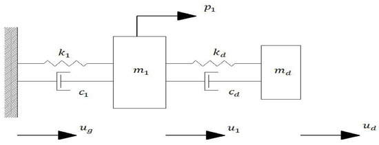
Figure 1.
Diagram depicting a damped single-degree-of-freedom (SDOF) system.
The Sydney Tower in Australia, the John Hancock Building in Boston, and the Chiba Port Tower in Japan are examples of buildings that utilize tuned mass dampers (TMDs) in their structural systems. Initially, TMDs were primarily employed to mitigate structural response to wind-induced vibrations. However, in recent years, numerous numerical studies and experimental tests have focused on utilizing TMDs to reduce structural response under seismic forces.
The frequency of a tuned mass damper is precisely adjusted to match a desired frequency. Once this frequency synchronization is achieved, the TMD is deliberately shifted in phase relative to the structural movement. This intentional phase difference results in a force being applied to counteract the structural motion, thereby dissipating the forces.
A tuned mass damper can be characterized by three key parameters:
Mass ratio: This refers to the ratio of the mass of the damper to the total mass of the single-degree-of-freedom (SDOF) system or the generalized mass for a specific mode of vibration of a multiple-degrees-of-freedom (MDOF) system [33].
Frequency ratio: Frequency ratio refers to the ratio between the fundamental frequency of the damper and the natural frequency of a single-degree-of-freedom (SDOF) system or the frequency corresponding to the first mode of vibration of a multiple-degrees-of-freedom (MDOF) system [33].
Damping ratio: The damping ratio of the TMD is (Zhou 2014) calculated by:
In a single-degree-of-freedom system attached to a TMD, the parameters are as follows:
: mass, damping, and the stiffness of the main structure.
: mass, damping, and the stiffness of the tuned mass damper.
: acceleration, velocity, and the displacement response of the main structure.
: acceleration, velocity, and the displacement response of the tuned mass damper.
: excitation force.
The equations on movement are as follows:
Primary mass:
Tuned mass damper:
The goal of using tuned mass dampers is to minimize structural displacement when exposed to external excitations. This is achieved by aligning the frequency of the damper with that of the structure, adjusting the damper to match the primary time period of the structure.
Considering an external excitation, the alternative excitation can be expressed as follows:
From this, the following relationships are derived:
where and are swing domain and phase difference, respectively. The critical case is related to the resonance condition (), and the response is as follows:
The analysis reveals that the response of the tuned mass is out of phase by 90 degrees compared to the response of the main mass, resulting in energy dissipation.
Without a tuned mass damper (TMD) attached to the structure, the response of the system is as follows:
To compare these two cases, the above equation is expressed in terms of the equivalent damping ratio:
The equation mentioned illustrates how the damper parameters contribute to the overall damping of the system. According to these equations, increasing the mass ratio enhances structural damping but is subject to certain limitations. Conversely, decreasing the damping factor of the damper increases damping which, in turn, leads to relative displacement but also has its limitations.
3. Structural Models
This study utilizes three reinforced concrete buildings of 10, 13, and 16 stories subjected to six earthquakes. The modeling process is conducted using MATLAB, and the characteristics of the modeled structures are evaluated using SAP2000. The study focuses on assessing the total response of the structures to confirm their linear response [34].
It is assumed that the mass of each story is lumped, resulting in a diagonal mass matrix for the structure. The stiffness matrix of reinforced concrete is determined based on the column stiffness of each story, while the damping matrix is evaluated using the mass matrix, stiffness matrix, and modal damping assumptions. The damping matrix of the structure is calculated as follows:
where and are damping ratio and natural frequency for each vibration, respectively [34].
To control the structure, variously tuned mass dampers are strategically placed at different levels. Using a constant mass ratio of 10% for each TMD, different configurations of TMDs are employed in the structure, categorized as single, double, and triple groups distributed across different levels.
The significant mass added to each story necessitates careful consideration of the equipment required to install the TMDs, which can increase the overall building dimensions. Therefore, distributing TMDs across different levels while maintaining a constant total mass can be an effective strategy to reduce the required equipment and structural dimensions while achieving similar structural performance compared to having a single TMD per story. The subsequent section will delve into the results obtained from the structural analysis.
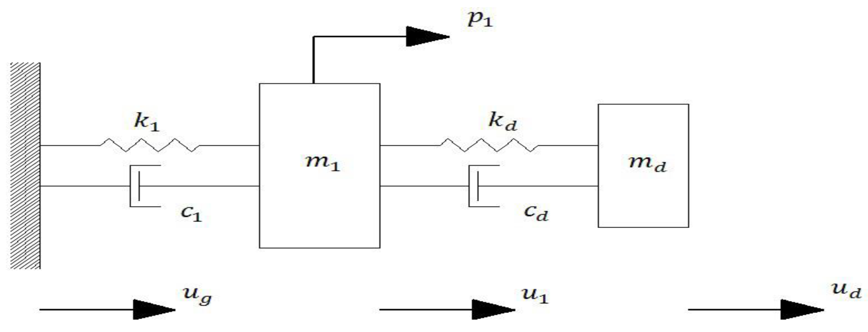
Figure 2 depicts an MDOF system with a TMD for reference.
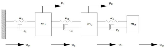
Figure 2.
Diagram of damped MDOF system.
The motion equations for a multiple-degrees-of-freedom (MDOF) system are as follows:
In the equations above:
Equation (24) represents the overall structural equation, and an additional secondary equation, such as Equation (25), is included for each story where a TMD is installed. Solving these differential equations enables the evaluation of the structure’s displacement and acceleration.
Similar to the approach used in the single-degree-of-freedom (SDOF) system, these differential equations are primarily solved using the Newmark-beta method. By substituting the appropriate equations and factors into Equations (22) and (24):
The displacement matrix of the original structure and TMD are as follow:
By considering factors A1 to A8 and factors Lj1 to Lj5 as the following, the numerical calculation of equation is conducted:
and
A1, A2, A3, and A4 factors are matrix and A5, A6, A7, and A8 are matrix. In Lj1 to Lj5 scalar factors, j represents the desired story.
By considering and :
which:
Equation (29) is evaluated as follows:
By placing in Equation (28) in each level of the structure:
By assuming Rj1 and Rj2 factors:
Equation (33) is evaluated as follows:
The matrix form of Equation (34), is as follows:
This equation can be rearranged as follows:
Therefore, using the matrix solution of Equation (36), structural acceleration and TMD acceleration are calculated in the next step as follows:
By evaluating the structural acceleration at each time step and employing Equations (39)–(42), the displacement, structural velocity, and TMD response can be calculated as follows:
By evaluating the displacement and structural acceleration under different earthquakes, the efficiency of TMDs is discussed.
4. Result Interpretation
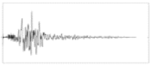
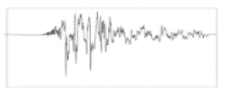
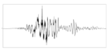
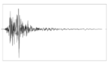
In this study, six different earthquakes of various and ratios are selected. Three structural models with 10, 13, and 16 stories were analyzed under these earthquakes. The considered records are near-fault earthquakes which are presented in Table 1.

Table 1.
Characteristics of earthquakes.
Near-fault records represent a specific type of earthquake characterized by a distinct pulse, attracting recent research interest. These earthquakes occur near the fault line and are oriented perpendicular to the fault direction, making them relevant for the structural analysis conducted in this research.
The impact of structural acceleration extends to non-structural elements. While minimizing deformation is crucial, reducing the necessity for deformation takes precedence due to the relative displacement of the structure. Consequently, the effect of TMDs in this study is considered a secondary priority.
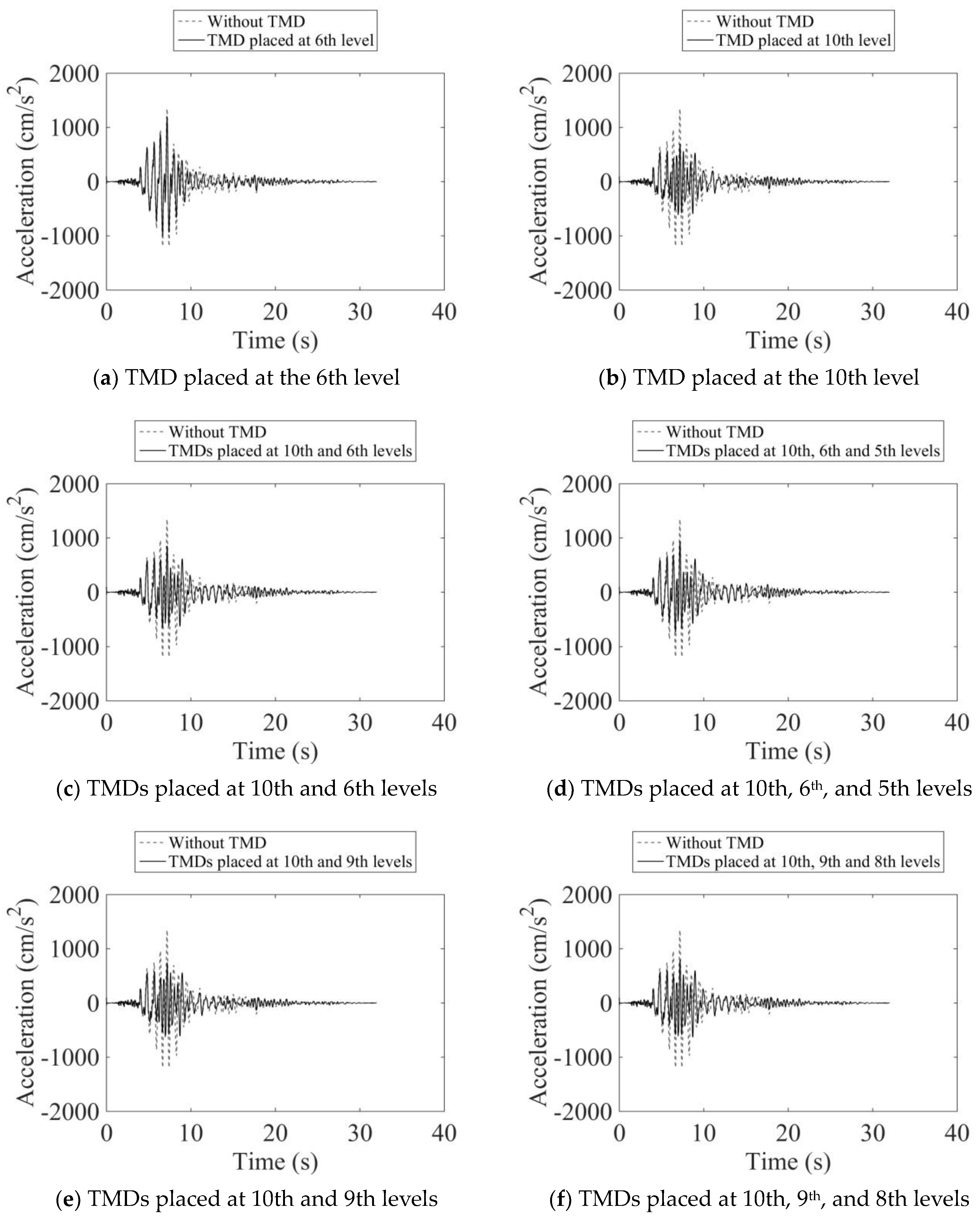
Based on the analysis, the maximum acceleration experienced by the 10-story structure with a TMD placed on the roof floor is 40% to 50% lower compared to a structure without a TMD. This reduction holds true for earthquakes such as the Chichi, Kobe, Kocaeli, and Northridge earthquakes. For the Imperial Valley and Lomaprieta earthquakes, this reduction is around 30%.
Figure 3 and Figure 4 suggest that placing a single TMD at lower levels results in reduced acceleration, while the optimal placement for TMDs is at higher levels of the structure. Furthermore, employing multiple TMDs at different heights yields comparable results to a single TMD. Notably, placing TMDs at levels 8, 9, and 10 of a 10-story structure yields favorable outcomes. The strategic distribution of TMDs across height levels can enhance the reduction of structural dimensions and improve overall performance.
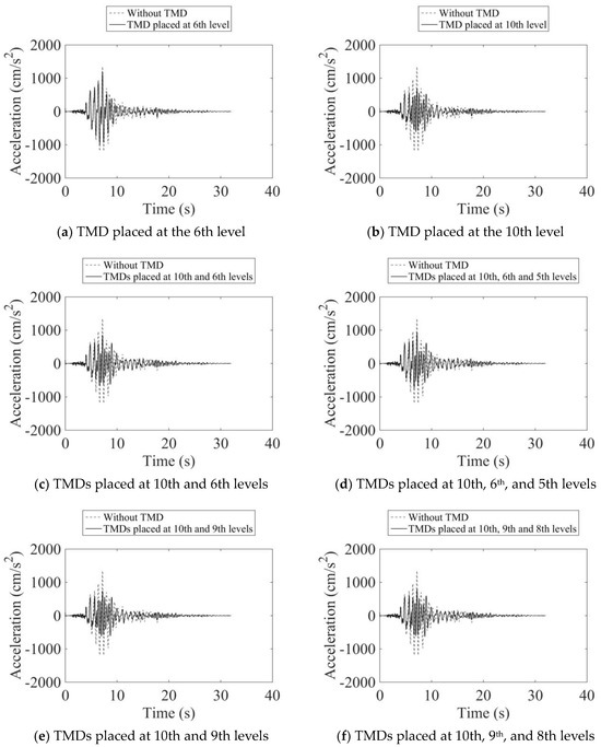
Figure 3.
Acceleration history of the 10-story structure under the Kobe earthquake.
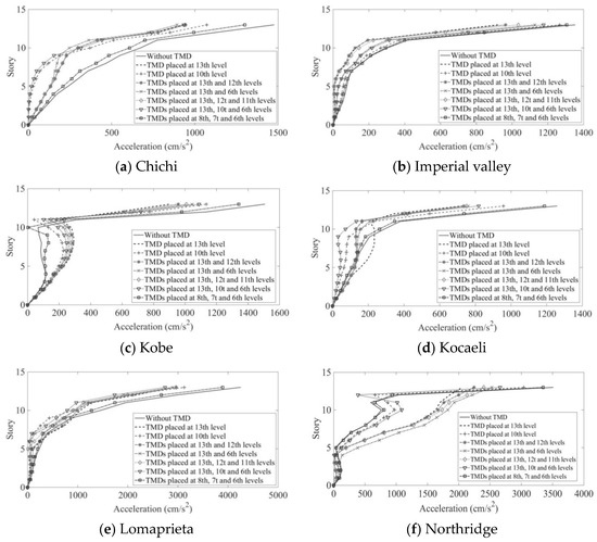
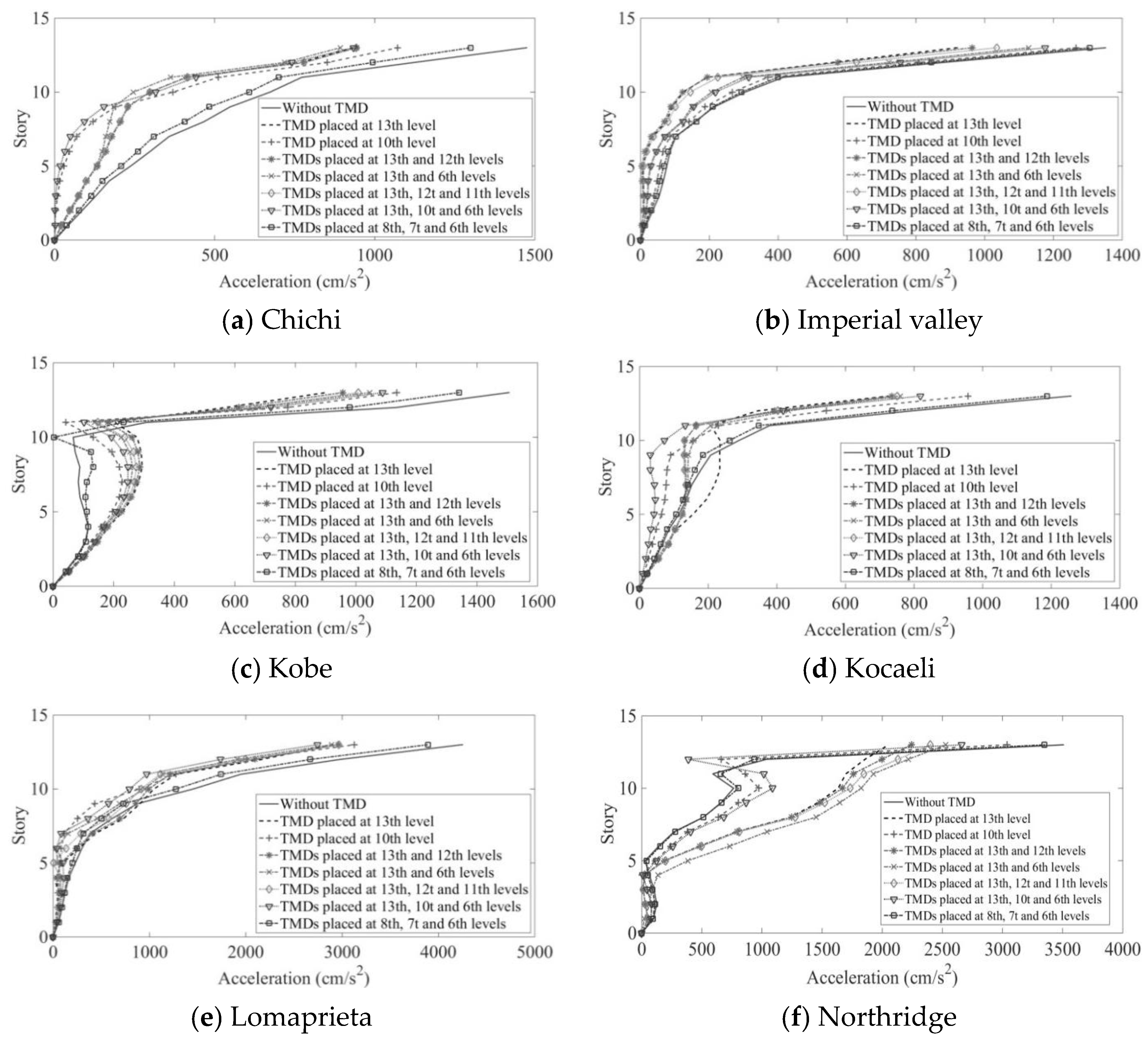
Figure 4.
The acceleration of different stories of the structure under the maximum acceleration of the total structure.
Figure 4 and Figure 5 illustrate that in 13- and 16-story structures, there is a reduction of 35% to 45% in structural acceleration. However, it is observed that as the height of the structure increases, the mitigating effect of a TMD on higher structures diminishes. Consequently, the reduction in acceleration in the 16-story structure is approximately 35%, while in the 13-story structure, it increases to around 45%.

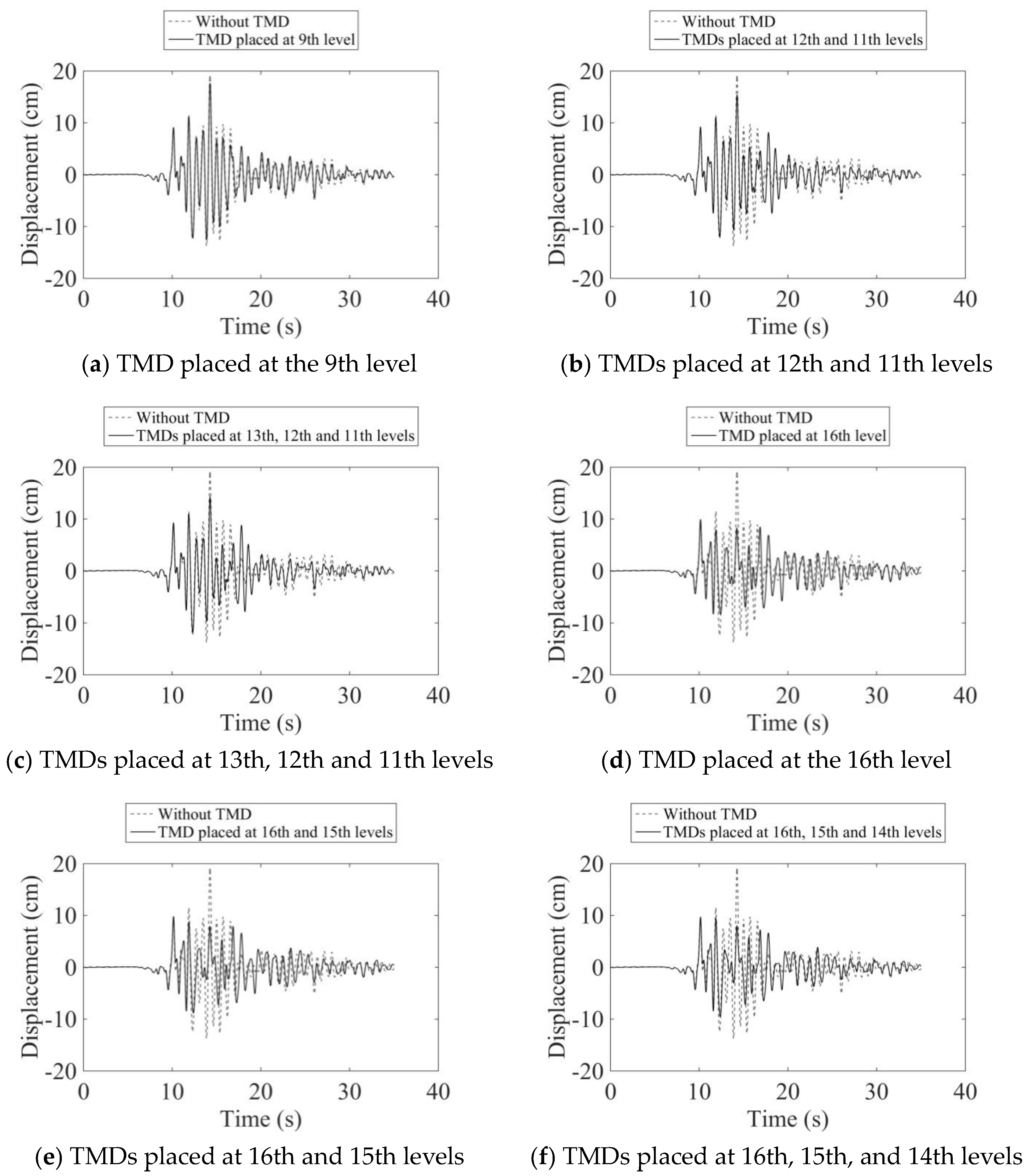
Figure 5.
Displacement history of the 16-story structure under Kocaeli earthquake.
Figure 5 also reveals a distinct behavior when the TMD is placed at the middle level of the structure. Placing the TMD at the middle level not only fails to reduce structural response but can also lead to undesirable behavior.
Placing the TMD at the middle levels of the structure leads to a failure in the acceleration plot, with the desired floor becoming the inflection point of the structure.
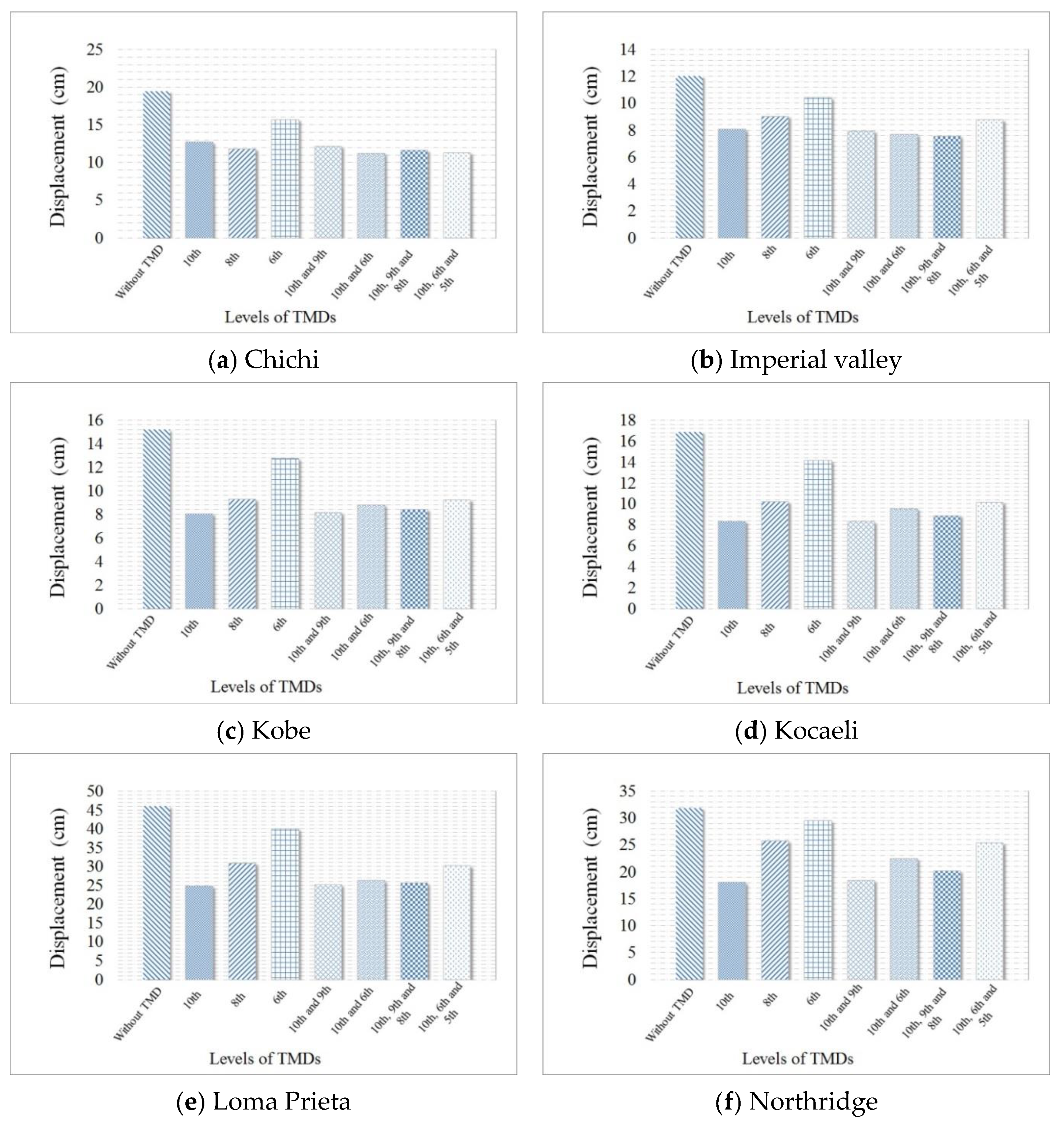
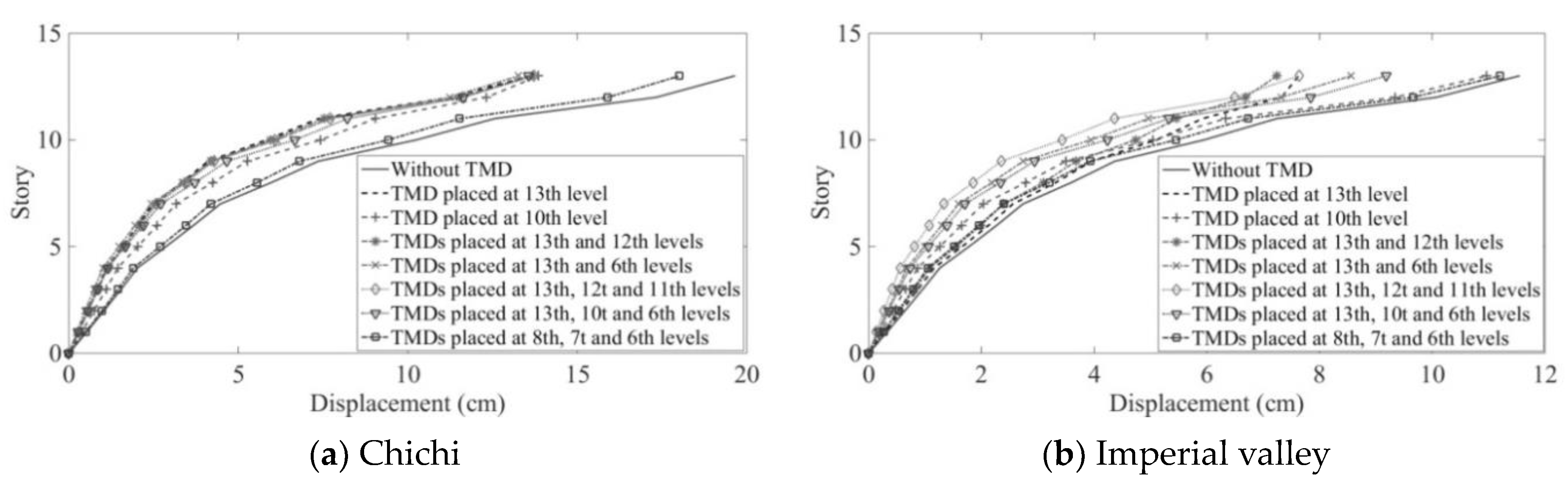
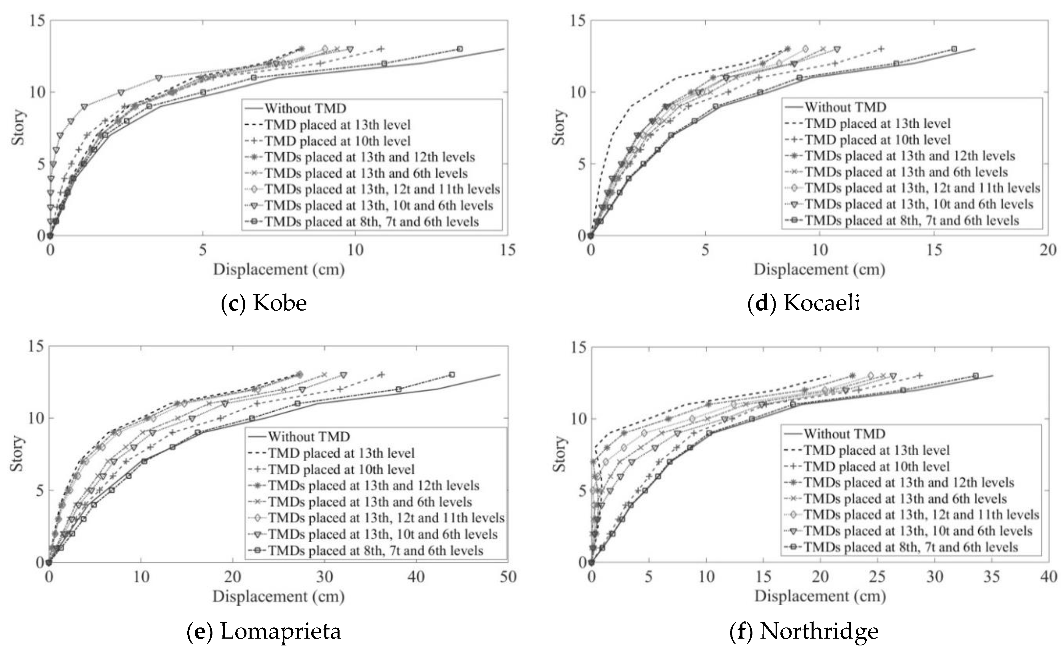
A widely used method in engineering to assess the effectiveness of control systems is to compare the relative displacement of stories and the maximum displacement of the structure. The displacement of the structure is depicted in Figure 6 and Figure 7. It is evident that the maximum displacement of the structure with a TMD experiences a significantly greater reduction compared to the structure without a TMD.
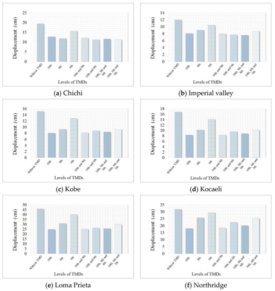
Figure 6.
The maximum acceleration of the 10-story structure under 6 different earthquakes.

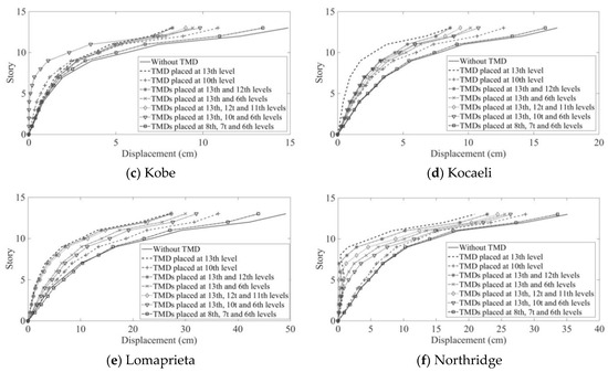
Figure 7.
The displacement of different stories of the structure under the maximum displacement of the total structure.
Based on the findings, it is observed that in the 10-story structure, the displacement reduction with a TMD ranges from 35% to 50% compared to the structure without a TMD. This reduction is consistent across various earthquakes with different frequencies.
Increasing the height of the structure leads to a notable decrease in maximum displacement. In the case of 13- and 16-story structures, applying a TMD results in up to a 50% reduction in structure displacement during certain earthquakes.
Placing TMDs at lower levels yields lower displacement reduction, while placing them at middle levels can be inefficient in reducing displacement. Therefore, higher levels of the structure are deemed the optimal placement for TMDs.
Distributing TMDs vertically results in favorable outcomes, showcasing a more unified behavior in displacement. This approach reduces the maximum displacement and significantly decreases drift in other stories compared to placing a TMD in a single story. Moreover, distributing the heavy mass of TMDs across multiple stories reduces the structural dimensions of the affected story, justifying the use of TMDs.
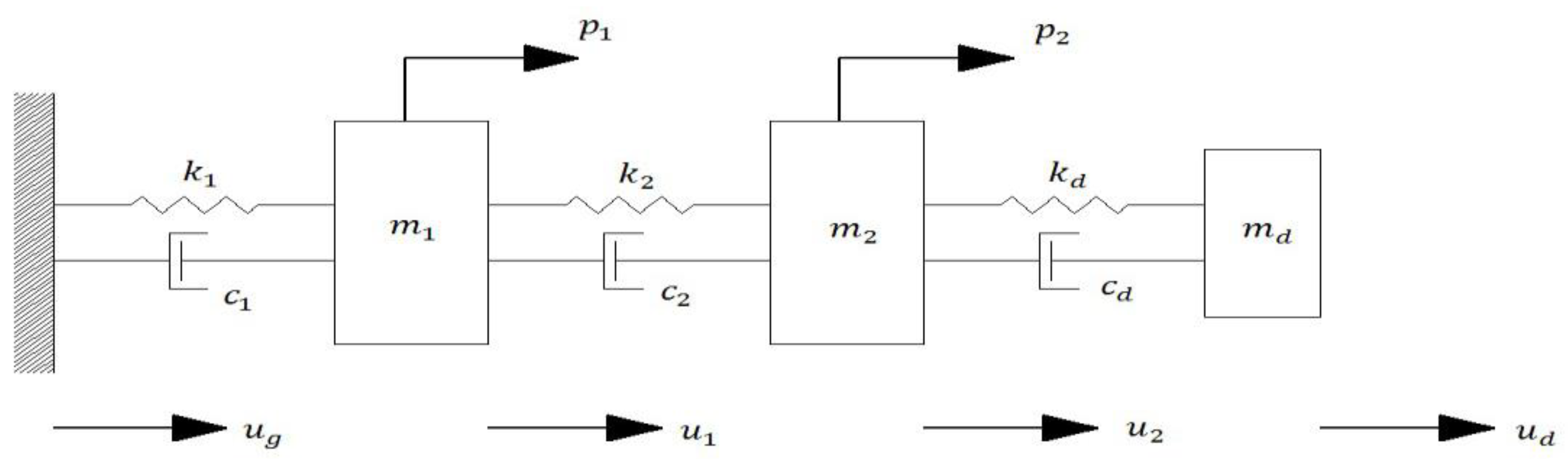
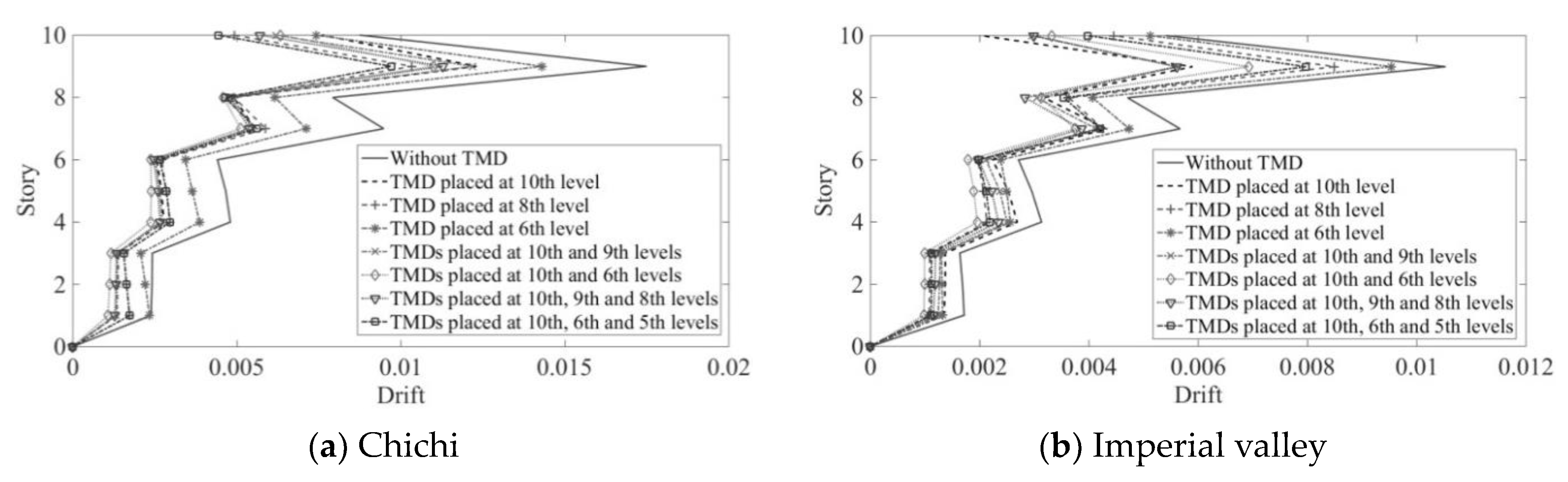
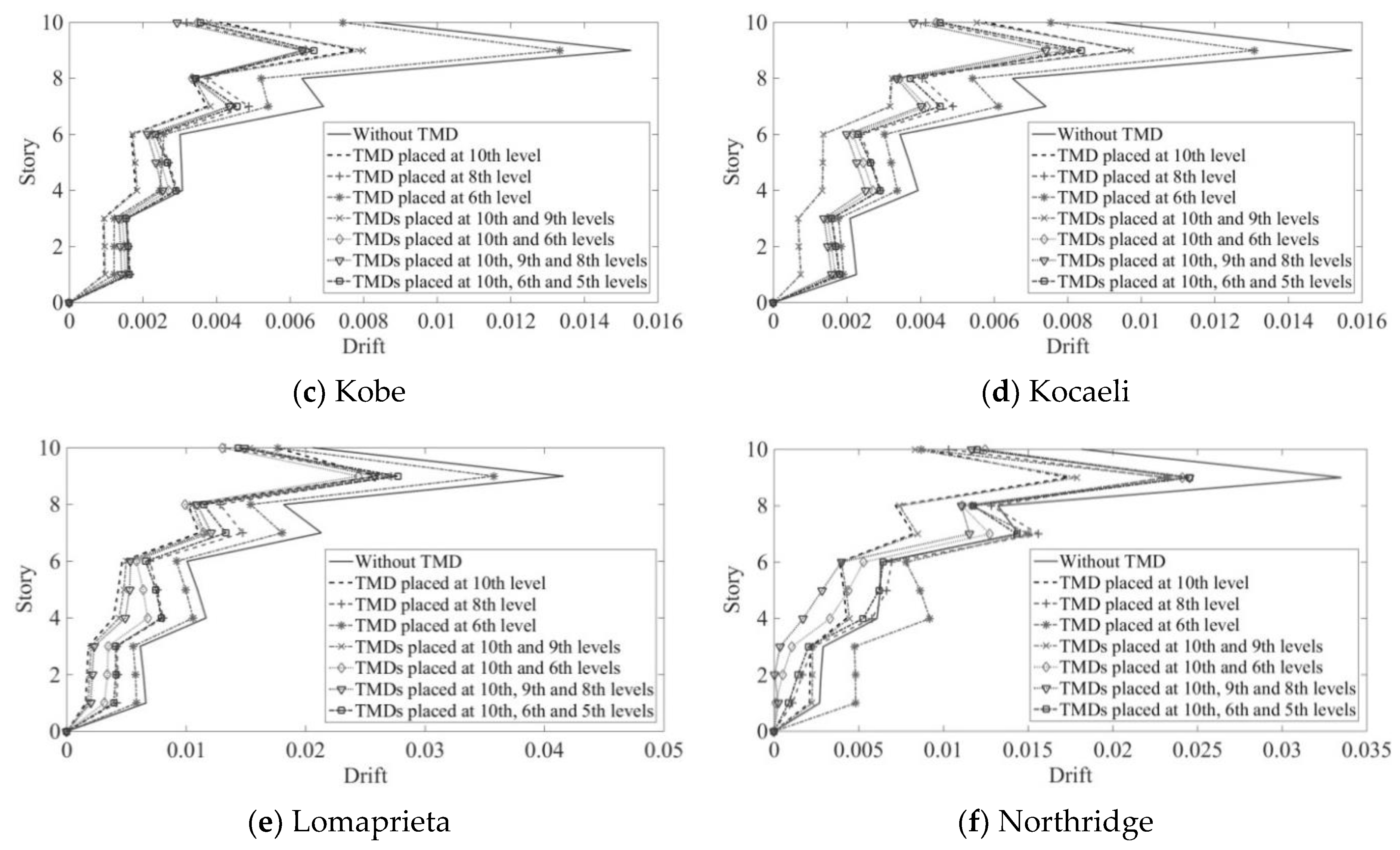
Figure 8 and Figure 9 demonstrate that distributing TMDs towards the top of the structure, such as one-third of the way to the top, yields better results. Employing multiple TMDs and distributing them in higher levels of structures leads to more effective outcomes in displacement reduction and structural behavior, encouraging further research in this area.
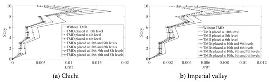
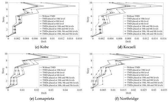
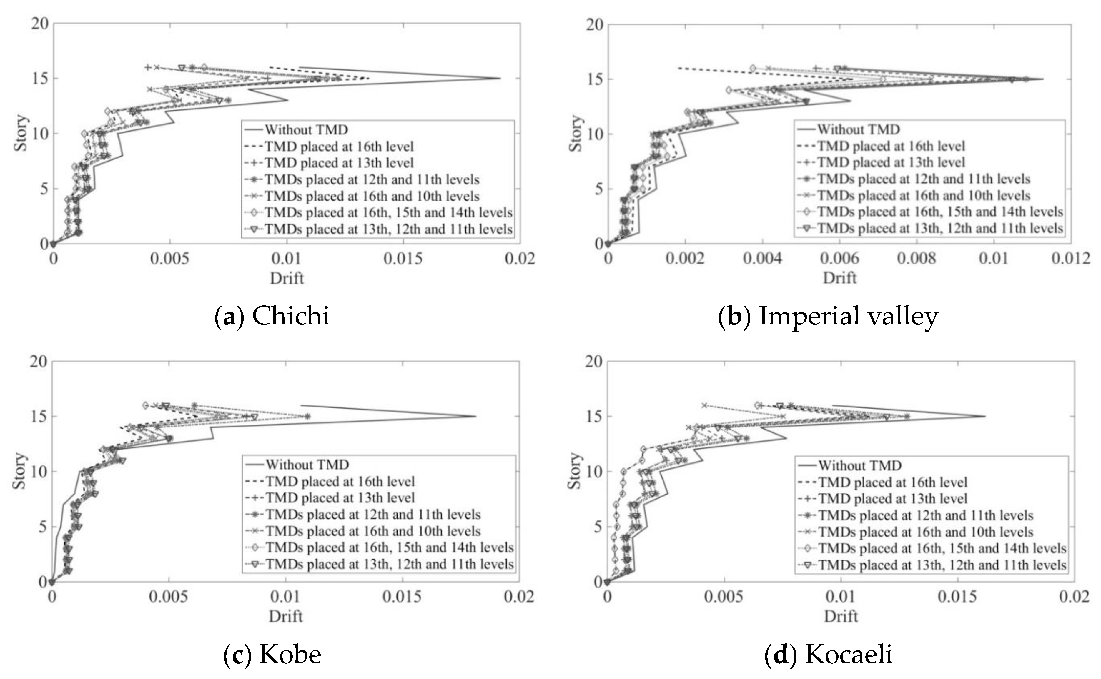
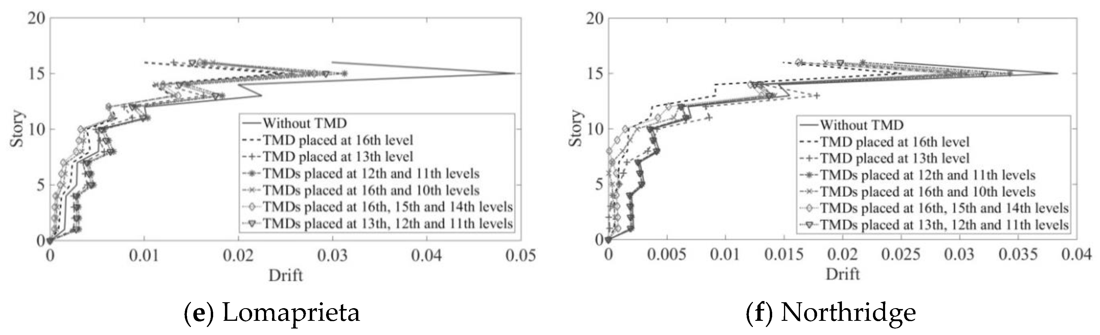
Figure 8.
Drift diagrams of the 10-story structure under 6 different earthquakes.
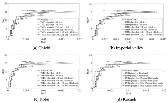
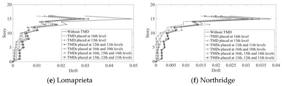
Figure 9.
Drift diagrams of the 16-story structure under 6 different earthquakes.
A commonly used performance metric among engineers is comparing relative drift, often expressed as the angle of relative drift, which is considered the best damage index.
The drift of the structure is illustrated in Figure 8 and Figure 9, showing a significant reduction in drift when TMDs are utilized. The maximum drift in the 10-story structure decreases by 45% to 65%. In 13- and 16-story structures, a reduction of 40% to 60% in maximum drift is observed, highlighting the effectiveness of distributing and placing TMDs at different heights throughout the structure. Thus, better outcomes can be achieved by employing multiple TMDs distributed vertically.
These results underscore the significant role of multiple TMDs distributed vertically. Vertical distribution of TMDs helps control the behavior of the structure across different levels, leading to reduced relative drift between stories and, consequently, reduced drift across all stories.
Analysis of the drift diagrams reveals that the maximum drift occurs at a level that is one-third of the total height of the structure. Therefore, distributing TMDs in the top third of the structure results in both reduced maximum displacement, as discussed in the previous section, and reduced maximum drift of the structure.
This study concludes that using TMDs in select stories, especially in levels where irregularities occur or in structures facing torsional issues, can effectively modify irregularities in height and address structural problems.
5. Conclusions
In this study, the components and functioning of passive control devices, specifically TMDs, are introduced as tools to reduce vibrations induced by earthquakes in structures. An SDOF system with a TMD is introduced to understand the structural response, revealing a 90-degree difference in the tuned mass response compared to the original mass response, leading to energy dissipation. Subsequently, three MDOF systems of varying heights (10, 13, and 16 stories) are analyzed under six near-fault earthquakes.
The key findings from the analysis are as follows:
- -
- Structures equipped with a TMD experience a 40% to 50% reduction in maximum acceleration compared to those without a TMD. Similar reductions of 35% to 45% are observed in 13- and 16-story structures.
- -
- Placing multiple TMDs vertically can further reduce acceleration by up to 50%.
- -
- TMD implementation reduces maximum displacement of the structure by up to 50%.
- -
- Increasing structure height diminishes the TMD’s effect on maximum acceleration.
- -
- The maximum drift of structures with a TMD is reduced by 45% to 65% in 10-story structures and 40% to 60% in 13- and 16-story structures compared to structures without a TMD.
- -
- Multiple TMDs contribute to more favorable structural behavior compared to single-TMD structures, especially when distributed vertically to control behavior across heights and minimize drift.
- -
- Placing TMDs at lower levels improves structural efficiency, while placing them at middle levels can lead to undesirable structural changes.
- -
- Distributing TMDs in the top third of the structure results in optimal structural behavior.
- -
- TMDs can effectively modify the behavior of irregular structures in terms of height.
These results highlight the significant impact of TMDs on reducing structural vibrations and improving overall structural performance, especially when strategically placed and utilized in multi-level structures.
Author Contributions
Conceptualization, H.N.; methodology, A.S.; software, A.S.; validation, H.N., A.S., N.E. and P.F.; formal analysis, A.S.; investigation, A.S.; resources, H.N. and A.K.; data curation, A.S.; writing—original draft preparation, A.S.; writing—review and editing, H.N., N.E. and P.F.; visualization, A.S.; supervision, H.N. and A.K.; project administration, H.N.; funding acquisition, H.N. All authors have read and agreed to the published version of the manuscript.
Funding
This research received no external funding.
Data Availability Statement
Data are contained within the article.
Conflicts of Interest
Author Nima Ezami was employed by the company GEI Consultants Inc. The remaining authors declare that the research was conducted in the absence of any commercial or financial relationships that could be construed as a potential conflict of interest.
References
- Joshi, A.S.; Jangid, R.S. Optimum parameters of multiple tuned mass dampers for base-excited damped systems. J. Sound Vib. 1997, 202, 657–667. [Google Scholar] [CrossRef]
- Ormondroyd, J.; Den Hartog, J.P. The theory of the dynamic vibration absorber. Trans. ASME 1928, 49, 021007. [Google Scholar] [CrossRef]
- Clark, A.J. Multiple passive tuned mass dampers for reducing earthquake induced building motion. In Proceedings of the Ninth Word Conference on Earthquake Engineering, Tokyo, Japan, 2–9 August 1988. [Google Scholar]
- Abe, M.; Fujino, Y. Dynamic characterization of multiple tuned mass dampers and some design formulae. Earthq. Eng. Struct. Dyn. 1994, 23, 813–835. [Google Scholar] [CrossRef]
- Tsai, H.C.; Lin, G.C. Optimum tuned mass dampers for minimizing steady-state response of support excited and damped system. Earthq. Eng. Struct. Dyn. 1993, 22, 957–973. [Google Scholar] [CrossRef]
- Chang, C.C. Mass dampers and their optimal designs for building vibration control. Eng. Struct. 1999, 21, 454–463. [Google Scholar] [CrossRef]
- Chang, C.C.; Hsu, C.T. Control performance of liquid column vibration absorbers. Eng. Struct. 1998, 20, 580–586. [Google Scholar] [CrossRef]
- Kareem, A.; Kline, S. Performance of multiple mass dampers under random loading. J. Struct. Eng.-ASCE 1995, 121, 348–361. [Google Scholar] [CrossRef]
- Rana, R.; Soong, T.T. Parametric study and simplified design of tuned mass dampers. Eng. Struct. 1998, 20, 193–204. [Google Scholar] [CrossRef]
- Sadek, F.; Mohraz, B.; Taylor, A.W.; Chung, R.M. A method of estimating the parameters of tuned mass dampers for seismic applications. Earthq. Eng. Struct. Dyn. 1997, 26, 617–635. [Google Scholar] [CrossRef]
- Xu, K.; Igusa, T. Dynamic characteristics of multiple substructures with closely spaced frequencies. Earthq. Eng. Struct. Dyn. 1992, 21, 1059–1070. [Google Scholar] [CrossRef]
- Jangid, R.S.; Datta, T.K. Performance of multiple tuned mass dampers for torsionally coupled system. Earthq. Eng. Struct. Dyn. 1997, 26, 307–317. [Google Scholar] [CrossRef]
- Lin, C.C.; Ueng, J.M.; Huang, T.C. Seismic response reduction of irregular buildings using passive tuned mass dampers. Eng. Struct. 1999, 22, 513–524. [Google Scholar] [CrossRef]
- Singh, M.P.; Singh, S.; Moreschi, L.M. Tuned mass dampers for response control of torsional buildings. Earthq. Eng. Struct. Dyn. 2002, 31, 749–769. [Google Scholar] [CrossRef]
- Pinkaew, T.; Lukkunaprasit, P.; Chatupote, P. Seismic effectiveness of tuned mass dampers for damage reduction of structures. Eng. Struct. 2003, 25, 39–46. [Google Scholar] [CrossRef]
- Villaverde, R.; Koyoama, L.A. Damped resonant appendages to increase inherent damping in buildings. Earthq. Eng. Struct. Dyn. 1993, 22, 491–507. [Google Scholar] [CrossRef]
- Kitts, L.; Wang, B.P.; Pilkey, W.D. Vibration reduction over a frequency range. J. Sound Vib. 1983, 89, 559–569. [Google Scholar] [CrossRef]
- Lee, C.L.; Chen, Y.T.; Chung, L.L.; Wang, Y.P. Optimal design theories and applications of tuned mass dampers. Eng. Struct. 2006, 28, 43–53. [Google Scholar] [CrossRef]
- Li, C.; Liu, Y. Ground motion dominant frequency effect on design of multiple tuned mass dampers. J. Earthq. Eng. 2004, 8, 89–105. [Google Scholar] [CrossRef]
- Ben Mekki, O.; Bourquin, F.; Maceri, F. Control of bridge structures with semi-active tuned mass damper. In Mechanics, Models and Methods in Civil Engineering; Springer: Berlin/Heidelberg, Germany, 2012; pp. 453–464. [Google Scholar]
- Bourquin, F.; Caruso, G.; Peigney, M.; Siegert, D. Magnetically tuned mass dampers for optimal vibration damping of large structures. Smart Mater. Struct. 2014, 23, 085009. [Google Scholar] [CrossRef]
- Chey, M.H.; Kim, J.U. Parametric control of structural responses using an optimal passive tuned mass damper under stationary Gaussian white noise excitations. Front. Struct. Civ. Eng. 2012, 6, 267–280. [Google Scholar] [CrossRef]
- Marano, G.C.; Greco, R.; Trentadue, F.; Chiaia, B. Constrained reliability-based optimization of linear tuned mass dampers for seismic control. Int. J. Solids Struct. 2007, 44, 7370–7388. [Google Scholar] [CrossRef]
- Maranoa, G.C.; Sgobbaa, S.; Grecob, R.; Mezzinab, M. Robust optimum design of tuned mass dampers devices in random vibrations mitigation. J. Sound Vib. 2008, 313, 472–492. [Google Scholar] [CrossRef]
- Takewaki, I. Robust building stiffness design for variable critical excitation. J. Struct. Eng.-ASCE 2002, 128, 165–1574. [Google Scholar] [CrossRef]
- Matta, E.; De Stefano, A. Robust design of mass-uncertain rolling-pendulum TMDs for the seismic protection of buildings. Mech. Syst. Signal Process. 2009, 23, 127–147. [Google Scholar] [CrossRef]
- Matta, E.; De Stefano, A. Seismic performance of pendulum and translational roof-garden TMDs. Mech. Syst. Signal Process. 2009, 23, 908–921. [Google Scholar] [CrossRef]
- Bekdaş, G.; Nigdeli, S.M. Mass ratio factor for optimum tuned mass damper strategies. Int. J. Mech. Sci. 2013, 71, 68–84. [Google Scholar] [CrossRef]
- Hadi, M.N.S.; Arfiadi, Y. Optimum design of absorber for MDOF structures. J. Struct. Eng.-ASCE 1998, 124, 1272–1280. [Google Scholar] [CrossRef]
- Marano, G.C.; Greco, R.; Chiaia, B. A comparison between different optimization criteria for tuned mass dampers design. J. Sound Vib. 2010, 329, 4880–4890. [Google Scholar] [CrossRef]
- Mazzon, L.; Frappa, G.; Pauletta, M. Effectiveness of Tuned Mass Damper in Reducing Damage Caused by Strong Earthquake in a Medium-Rise Building. Appl. Sci. 2023, 13, 6815. [Google Scholar] [CrossRef]
- Shahraki, M.A.; Kamgar, R.; Heidarzadeh, H. Damage-based design of multiple tuned mass dampers to improve the seismic performance of steel frame structures. Soil Dyn. Earthq. Eng. 2023, 173, 108062. [Google Scholar] [CrossRef]
- Zhou, Z. Effectiveness of Tuned Mass Dampers in Mitigating Earthquake Ground Motions in Low and Medium Rise Buildings. Master’s Thesis, The State University of New Jersey, New Brunswick, NJ, USA, 2014. [Google Scholar]
- Spencer, B.F., Jr.; Christenson, R.E.; Dyke, S.J. Next generation benchmark control problem for seismically excited buildings. In Proceedings of the Second World Conference on Structural Control, Kyoto, Japan, 22 March 1999. [Google Scholar]
Disclaimer/Publisher’s Note: The statements, opinions and data contained in all publications are solely those of the individual author(s) and contributor(s) and not of MDPI and/or the editor(s). MDPI and/or the editor(s) disclaim responsibility for any injury to people or property resulting from any ideas, methods, instructions or products referred to in the content. |
© 2024 by the authors. Licensee MDPI, Basel, Switzerland. This article is an open access article distributed under the terms and conditions of the Creative Commons Attribution (CC BY) license (https://creativecommons.org/licenses/by/4.0/).