
Behavior of Lightweight Self-Compacting Concrete with Recycled Tire Steel Fibers
 , , ,
, , ,  and
and
Abstract
:1. Introduction
2. Experimental Investigation
2.1. Materials
2.1.1. Cement Matrix
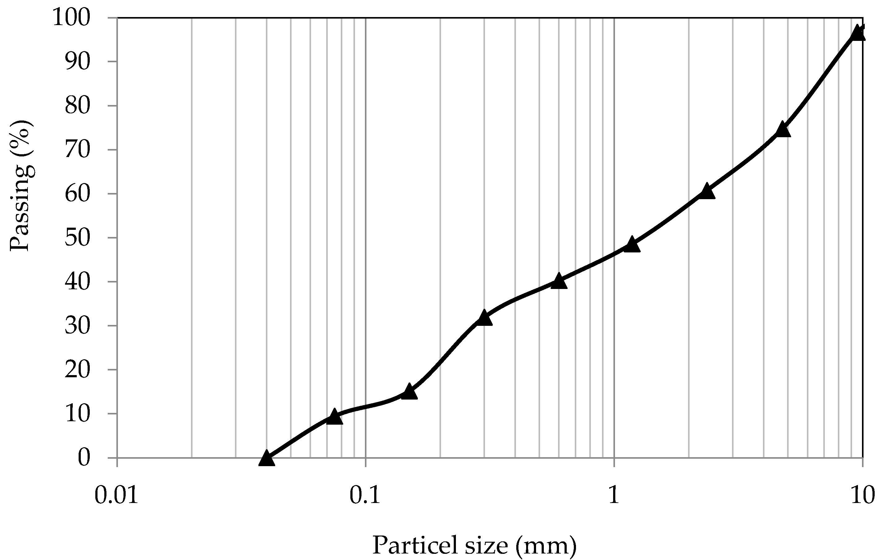
2.1.2. Aggregates
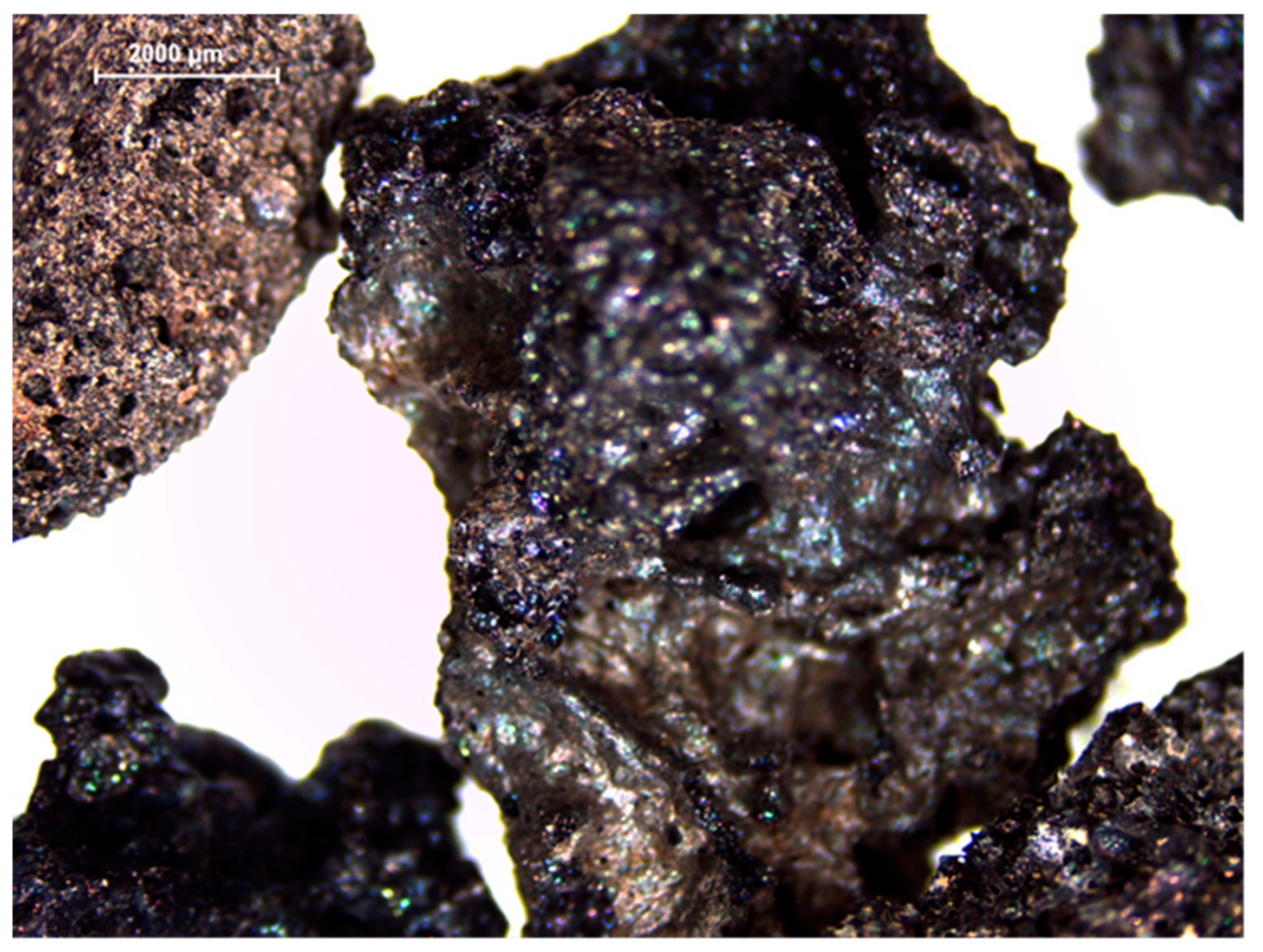
2.1.3. Recycled Tire Steel Fibers (RTSFs)
2.1.4. Steel Bars
2.2. Concrete Mixture Composition
2.3. Concrete Tests
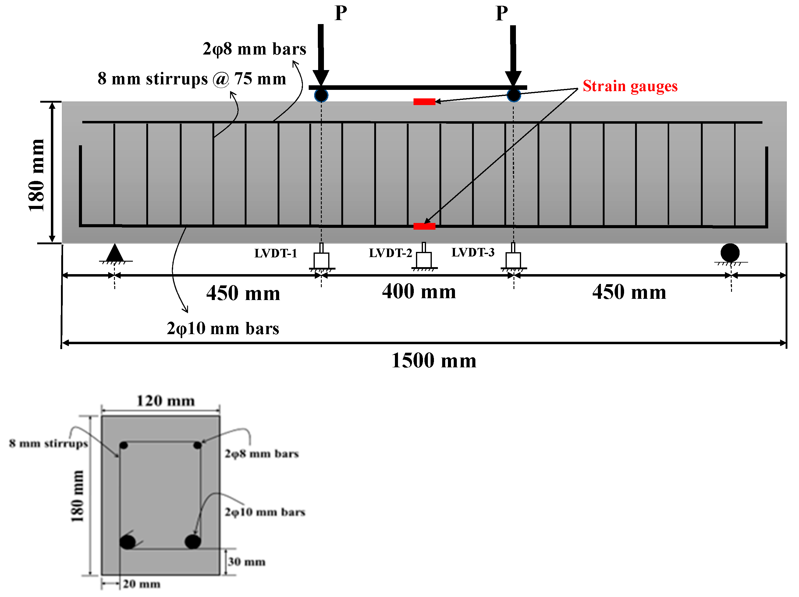
2.4. Beam Tests
3. Results of Concrete Tests
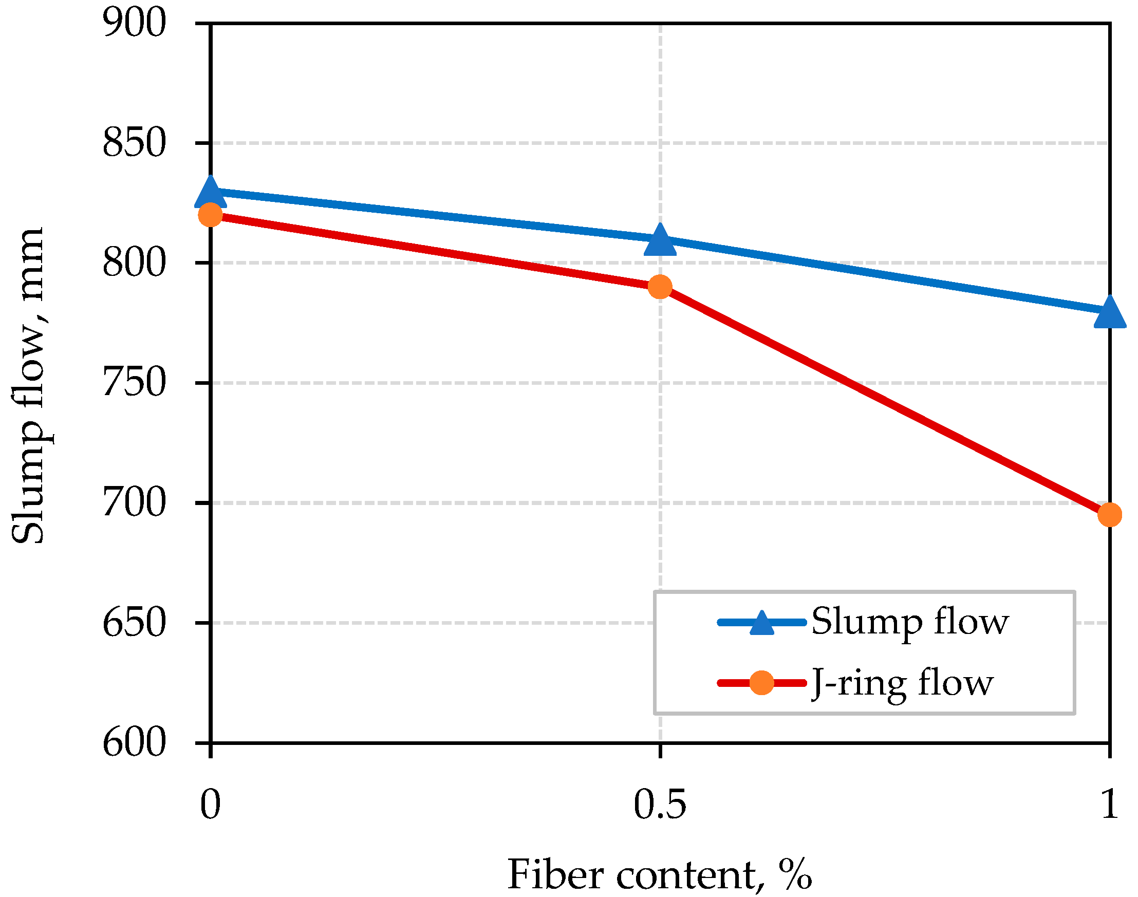
3.1. Fresh Properties
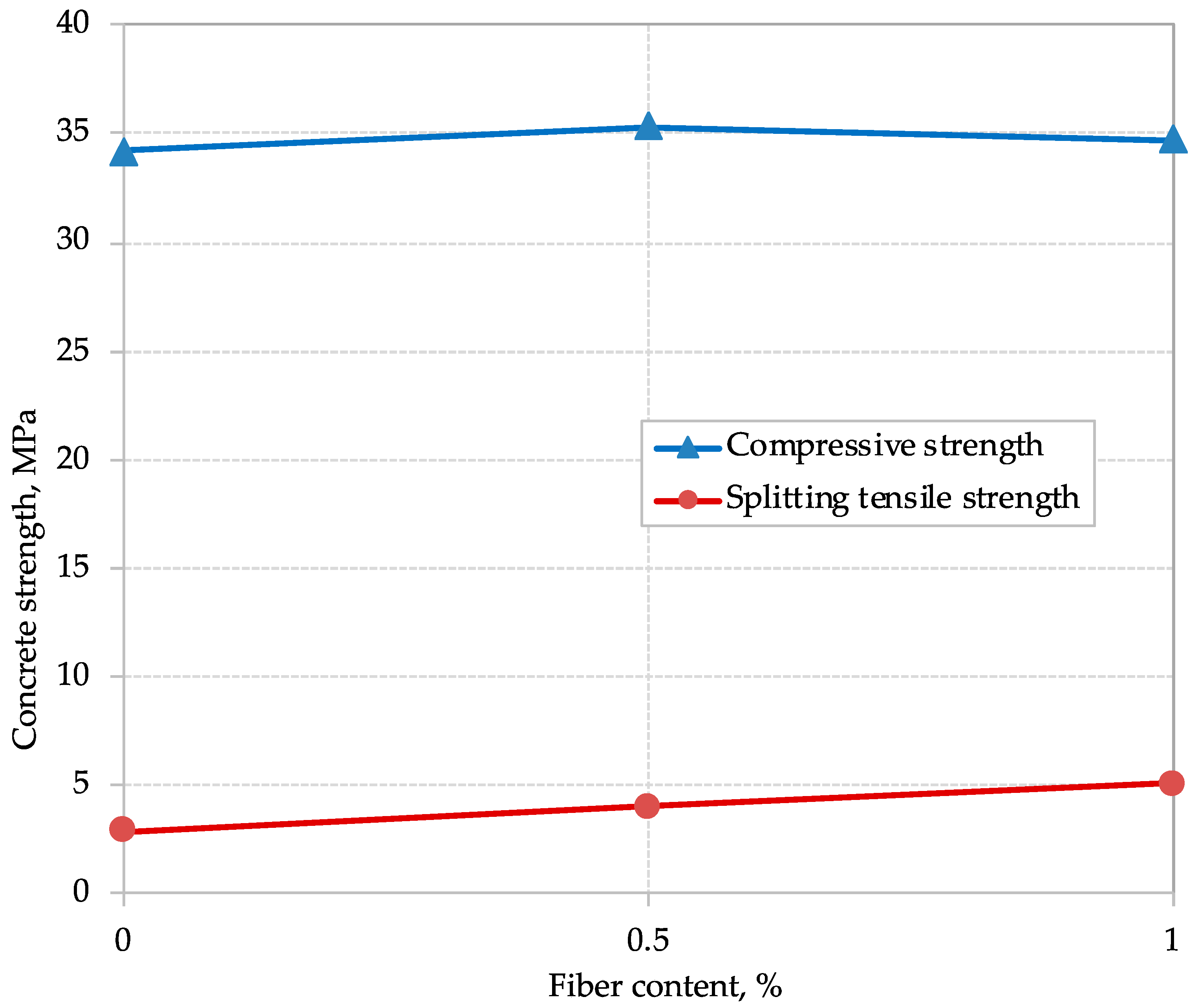
3.2. Compressive Strength
3.3. Splitting Tensile Strength
4. Beam Test Results
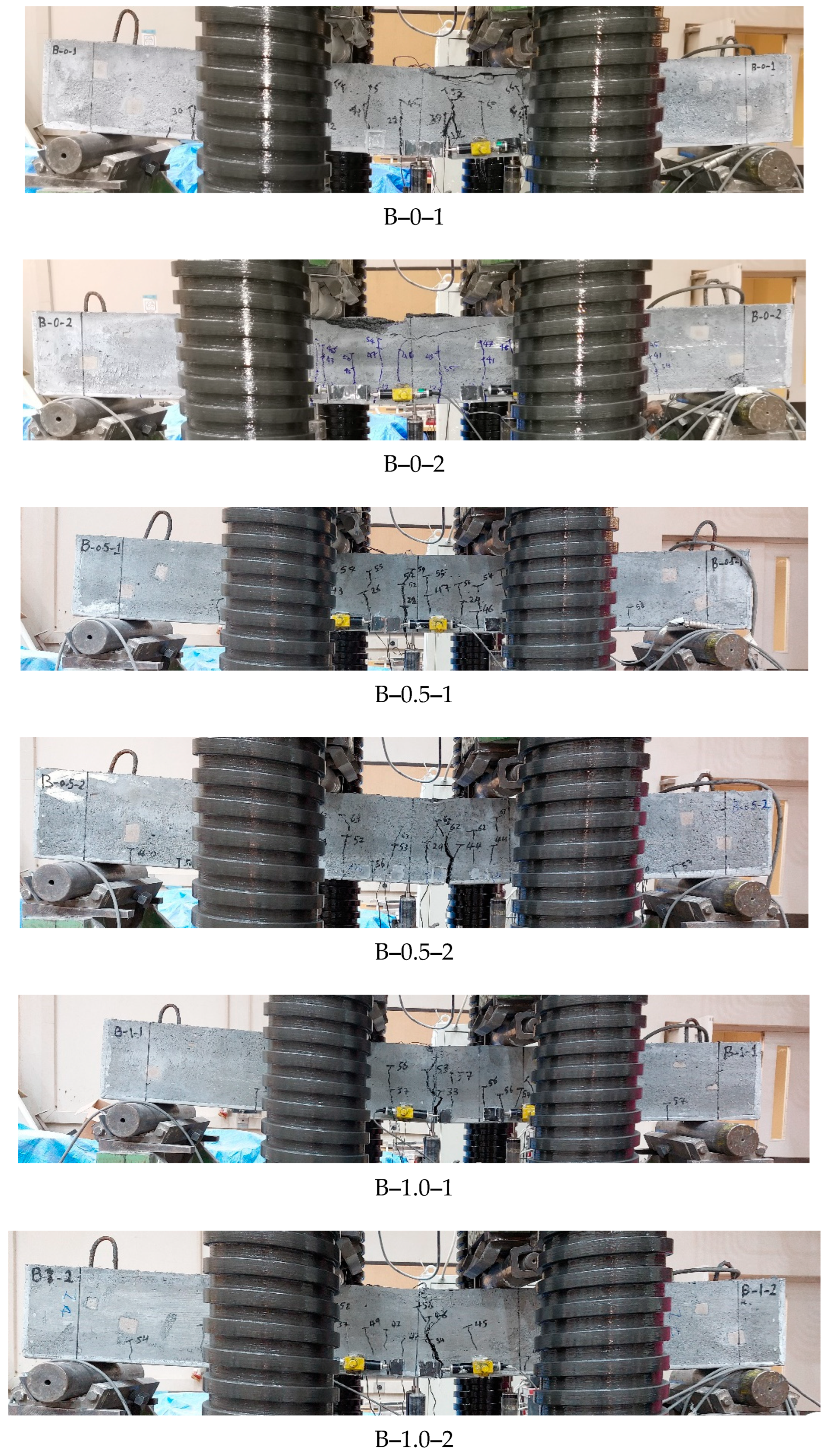
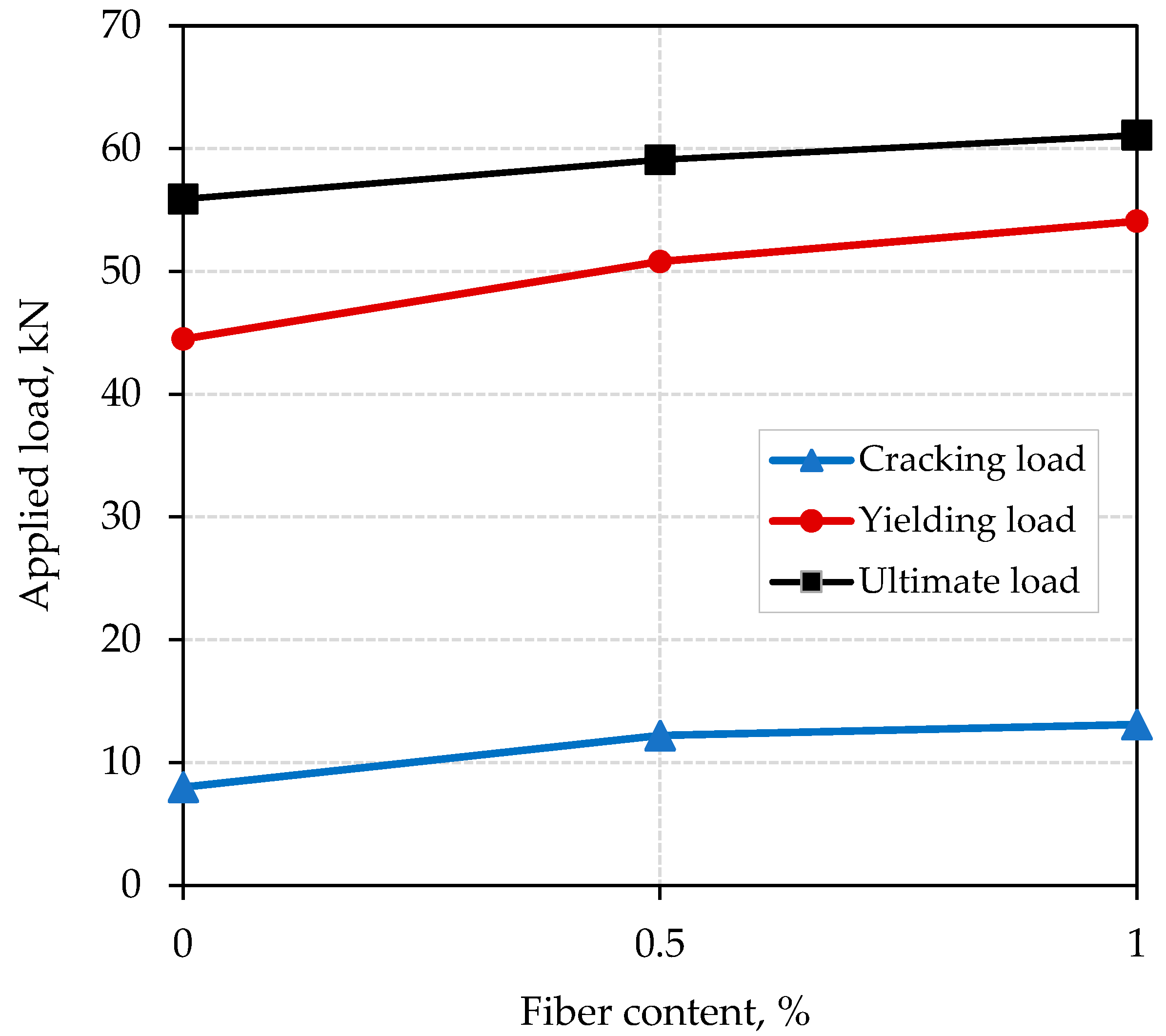
4.1. Load Capacity and Mode of Failure
4.2. Deflection and Ductility
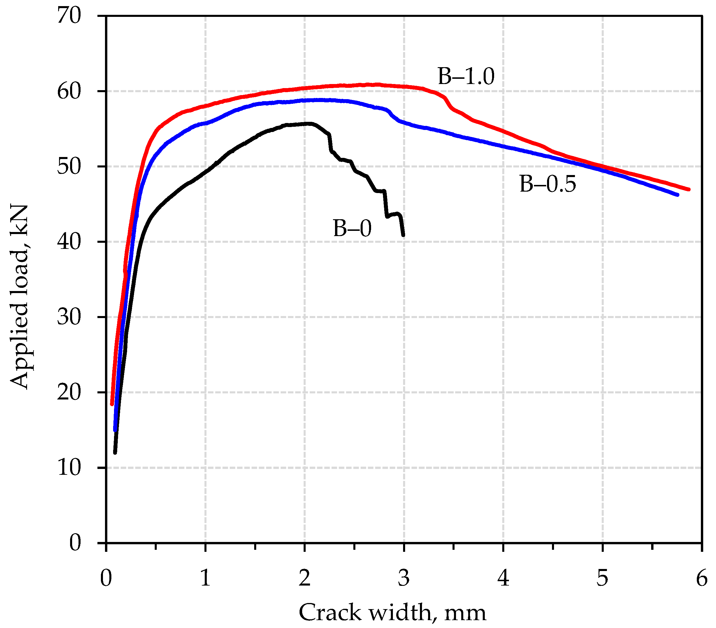
4.3. Cracking Behavior and Strains
5. Comparison of Predictions and Experimental Results
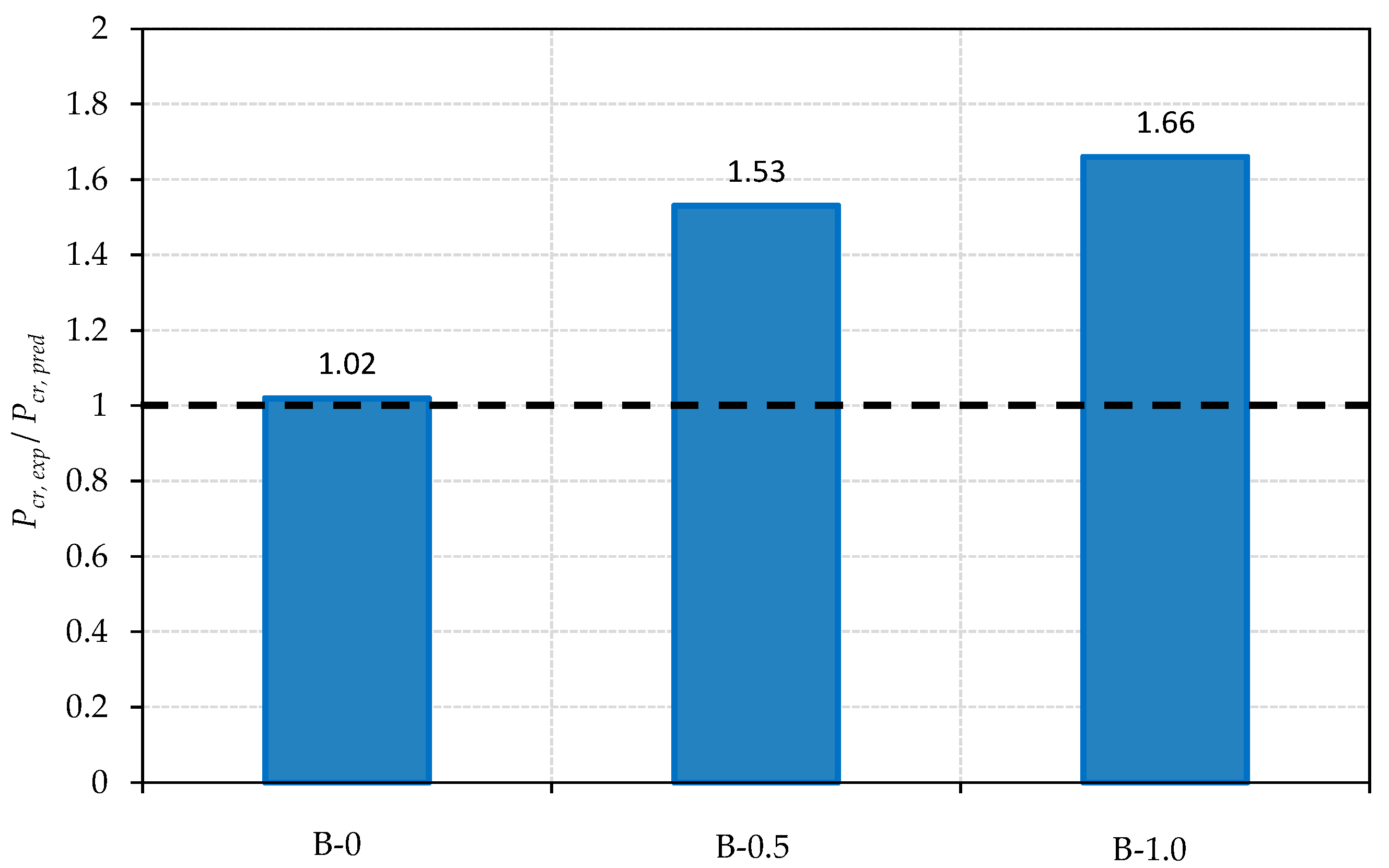
5.1. Cracking Load
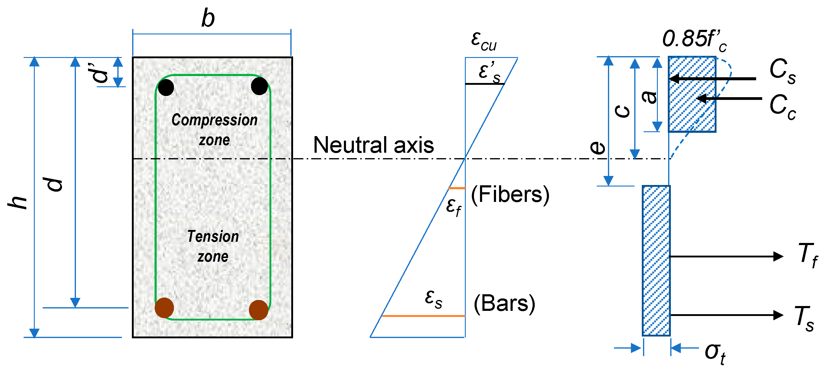
5.2. Ultimate Load
6. Conclusions
- The addition of RTSFs to the LWSCC mixtures resulted in slight decreases in the slump flow of the mixtures. However, the obtained slump flow values for the concrete mixtures remained well above the EFNARC-specified lower limit of 650 mm for SCC with sufficient flowability.
- The obtained fresh densities of the developed concrete mixtures fell within the range specified for structural lightweight concrete by both the ACI 318 code and Eurocode 2, despite the fibers’ effect on increasing the density of the fibrous concrete mixtures.
- The inclusion of RTSFs was found to significantly enhance the splitting tensile strength of the concrete mixtures. However, the compressive strength results show only a marginal improvement.
- The cracking load of the beams with 0.5 and 1.0% fiber contents increased by 52.5 and 63.8%, respectively, compared with the non-fibrous control beam. However, the corresponding increases in the ultimate load were 5.7 and 9.3%.
- The inclusion of RTSFs reduced the midspan deflection and crack width of the beams at service load level. Also, the RTSFs enhanced the ductility index by 12 and 16% for the beams with 0.5 and 1.0% fiber contents, respectively, over that of the non-fibrous control beam.
- The ACI 318 method accurately predicted the cracking load of the control beam without fibers. On the other hand, it provided conservative predictions for the beams containing RTSFs.
- The ACI 544.4R method was able to capture the beneficial effect of the RTSFs of enhancing the ultimate load of the beams, providing accurate and consistent predictions.
Author Contributions
Funding
Data Availability Statement
Acknowledgments
Conflicts of Interest
References
- Shideler, J.J. Lightweight aggregate concrete for structural use. ACI J. Proc. 1957, 54, 298–328. [Google Scholar]
- Hanson, J.A. Tensile strength and diagonal tension resistance of structural lightweight concrete. ACI J. Proc. 1961, 58, 1–40. [Google Scholar]
- Bentz, D.P.; Snyder, K.A. Protected paste volume in concrete: Extension to internal curing using saturated lightweight fine aggregate. Cem. Concr. Res. 1999, 29, 1863–1867. [Google Scholar] [CrossRef]
- ACI Committee 213. ACI 213R-03; Guide for Structural Lightweight Aggregate Concrete; American Concrete Institute: Farmington Hills, MI, USA, 2003. [Google Scholar]
- Alhnifat, R.S.; Abdel-Jaber, M.; Al-Dala’ien, R.N. Behavior of lightweight concrete incorporating pozzolana aggregate and expanded polystyrene beads. Eng. Sci. 2023, 25, 934. [Google Scholar] [CrossRef]
- ACI Committee 237. ACI 237R-07; Self-Consolidating Concrete; American Concrete Institute: Farmington Hills, MI, USA, 2007. [Google Scholar]
- Zhu, J.; Zhang, C.; Yu, W. Compressive properties of self-compacting concrete after cooling from high temperatures. Buildings 2022, 12, 1875. [Google Scholar] [CrossRef]
- Al-Negheimish, A.I.; El-Sayed, A.K.; Khanbari, M.O.; Alhozaimy, A.M. Long-term deflection of prestressed SCC hollow core slabs. Constr. Build. Mater. 2018, 189, 181–191. [Google Scholar] [CrossRef]
- Al-Negheimish, A.I.; El-Sayed, A.K.; Khanbari, M.O.; Alhozaimy, A.M. Structural behavior of prestressed SCC hollow core slabs. Constr. Build. Mater. 2018, 182, 334–345. [Google Scholar] [CrossRef]
- Kassimi, F.; El-Sayed, A.K.; Khayat, K.H. Performance of fiber reinforced self-consolidating concrete for repair of reinforced concrete beams. ACI Struct. J. 2014, 111, 1277–1286. [Google Scholar] [CrossRef]
- Ashteyat, A.; Obaidat, A.T.; Qerba’a, R.; Abdel-Jaber, M. Influence of basalt fiber on the rheological and mechanical properties and durability behavior of self-compacting concrete (SCC). Fibers 2024, 12, 52. [Google Scholar] [CrossRef]
- Abdel-Jaber, M.; Beale, R.; Makhoul, N. Self-compacting concrete (SCC) strength prediction via optimized duple-deep-learning model and distance ranked fire-hawk optimizer (DRFO). Civ. Eng. Archit. 2023, 11, 2447–2460. [Google Scholar] [CrossRef]
- Siamardi, K. Optimization of fresh and hardened properties of structural light weight self-compacting concrete mix design using response surface methodology. Constr. Build. Mater. 2022, 317, 125928. [Google Scholar] [CrossRef]
- Ting, T.Z.H.; Rahman, M.E.; Lau, H.H.; Ting, M.Z.Y. Recent development and perspective of lightweight aggregates based self-compacting concrete. Constr. Build. Mater. 2019, 201, 763–777. [Google Scholar] [CrossRef]
- Lotfy, A.; Hossain, K.M.A.; Lachemi, M. Lightweight self-consolidating concrete with expanded shale aggregates: Modelling and optimization. Int. J. Concr. Struct. Mater. 2015, 9, 185–206. [Google Scholar] [CrossRef]
- Abdelaziz, G.E. A study on the performance of lightweight self-consolidated concrete. Mag. Concr. Res. 2010, 62, 39–49. [Google Scholar] [CrossRef]
- Bogas, J.A.; Gomes, A.; Pereira, M.F.C. Self-compacting lightweight concrete produced with expanded clay aggregate. Constr. Build. Mater. 2012, 35, 1013–1022. [Google Scholar] [CrossRef]
- Vakhshouri, B.; Nejadi, S. Mix design of light-weight self-compacting concrete. Case Stud. Constr. Mater. 2016, 4, 1–14. [Google Scholar] [CrossRef]
- Fares, G.; El-Sayed, A.K.; Alhozaimy, A.M.; Al-Negheimish, A.I.; Albidah, A.S. Lightweight SCC development in a low-carbon cementitious system for structural applications. Materials 2023, 16, 4395. [Google Scholar] [CrossRef]
- Ranjbar, M.M.; Hosseinali Beygi, M.; Nikbin, I.M.; Rezvani, M.; Barari, A. Evaluation of the strength variation of normal and lightweight self-compacting concrete in full scale walls. Mater. Technol. 2011, 45, 571–577. [Google Scholar]
- Floyd, R.W.; Hale, W.M.; Bymaster, J.C. Effect of aggregate and cementitious material on properties of lightweight self-consolidating concrete for pre-stressed members. Constr. Build. Mater. 2015, 85, 91–99. [Google Scholar] [CrossRef]
- Bakouregui, A.S.; Mohamed, H.M.; Yahia, A.; Benmokrane, B. Axial load–moment interaction diagram of full-scale circular LWSCC columns reinforced with BFRP and GFRP bars and spirals: Experimental and theoretical investigations. Eng. Struct. 2021, 242, 112538. [Google Scholar] [CrossRef]
- Omar, A.T.; AbdelAleem, B.H.; Hassan, A.A.A. Performance of Stalite lightweight SCC beam-column joints under reversed cyclic loading. Eng. Struct. 2023, 288, 116182. [Google Scholar] [CrossRef]
- Ranjbar, M.M.; Madandoust, R.; Mousavi, S.Y.; Hashemi, S.J. Evaluation of the fluidity and mechanical properties of light-weight self-compacting concrete containing expanded polystyrene (EPS). In The Third International Conference on Concrete and Development, 27–29 April 2009; Building and Housing Research Center: Tehran, Iran, 2009; pp. 543–554. [Google Scholar]
- Wan, L.W.S.D.; Aslani, F.M.; Ma, G. Lightweight self-compacting concrete incorporating perlite, scoria, and polystyrene aggregates. J. Mater. Civ. Eng. 2018, 30, 04018178. [Google Scholar]
- Chen, H.-J.; Wu, K.-C.; Tang, C.-W.; Huang, C.-H. Engineering properties of self-consolidating lightweight aggregate concrete and its application in prestressed concrete members. Sustainability 2018, 10, 142. [Google Scholar] [CrossRef]
- Omar, A.T.; Hassan, A.A.A. Flexural performance and ductility of expanded slate lightweight self-consolidating concrete beams. ACI Struct. J. 2022, 119, 1277–1286. [Google Scholar]
- Garcia, S.L.G.; Lannes, C.V.; Carneiro, L.A.V.; Lara, R.C. Shear behavior of lightweight self-consolidating reinforced concrete beams without transverse reinforcement. Lat. Am. J. Solid. Struct. 2020, 17, e277. [Google Scholar] [CrossRef]
- Hossain, K.M.A.; Sathiyamoorthy, K.; Manzur, T.; Lotfy, A. Shear behavior of lightweight slag aggregate self-consolidating concrete beams. ACI Struct. J. 2020, 117, 259–268. [Google Scholar]
- El-Sayed, A.K.; Fares, G.; Albidah, A.S.; Alhozaimy, A.M.; Al-Saawani, M.A.; Al-Negheimish, A.I. Assessment of concrete shear resistance of lightweight SCC beams containing scoria aggregates. J. Build. Eng. 2023, 78, 107591. [Google Scholar] [CrossRef]
- Alkhattat, S.S.; Al-Ramahee, M.A. Flexural strength of fibrous light-weight self-compacted concrete beams. J. Phys. Conf. Ser. 1973, 2021, 012221. [Google Scholar] [CrossRef]
- Hasan, H.S.; Al-Hadithi, A.I.; Yousif, Y.K. Properties of self-compacting lightweight aggregate concrete containing polyolefin fibers. In Proceedings of the 8th International Engineering Conference on Sustainable Technology and Development (IEC), Erbil, Iraq, 23–24 February 2022; pp. 42–48. [Google Scholar]
- Choi, J.-S.; Lee, H.-J.; Yuan, T.-F.; Yoon, Y.-S. Shear strength of steel fiber reinforced lightweight self-consolidating concrete joints under monotonic and cyclic loading. Constr. Build. Mater. 2023, 363, 129829. [Google Scholar] [CrossRef]
- Al-Hadithi, A.I.; Hilal, N.N.; Al-Gburi, M.; Midher, A.H. Structural behavior of reinforced lightweight self-compacting concrete beams using expanded polystyrene as coarse aggregate and containing polyethylene terephthalate fibers. Struct. Concr. 2023, 24, 5808–5826. [Google Scholar] [CrossRef]
- Abdulkareem, M.; Ayeronfe, F.; Jassam, T.M.; AlAteah, A.H.; Al-Sodani, K.A.A.; Al-Tholaia, M.M.H.; Yam, H.; Ganiyu, A.; Alih, S.C. Compressive and flexural strengths of bio-recycled concrete incorporated with kenaf fibre. J. Nat. Fibers 2024, 21, 2296913. [Google Scholar] [CrossRef]
- Butt, F.; Ahmad, A.; Ullah, K.; Zaid, O.; Ahmed Shah, H.; Kamal, T. Mechanical performance of fiber-reinforced concrete and functionally graded concrete with natural and recycled aggregates. Ain Shams Eng. J. 2023, 14, 102121. [Google Scholar]
- Jaham, A.; Issa, C.A. Exploring the use of mixed waste materials (MWM) in concrete for sustainable construction: A review. Constr. Build. Mater. 2023, 398, 132476. [Google Scholar] [CrossRef]
- Liew, K.; Akbar, A. The recent progress of recycled steel fiber reinforced concrete. Constr. Build. Mater. 2020, 232, 117232. [Google Scholar] [CrossRef]
- Awolusi, T.F.; Oke, O.L.; Atoyebi, O.D.; Akinkurolere, O.O.; Sojobi, A.O. Waste tires steel fiber in concrete: A review. Innov. Infrastruct. Solut. 2021, 6, 34. [Google Scholar] [CrossRef]
- Alsaif, A.; Alshannag, M. Flexural behavior of portland cement mortars reinforced with hybrid blends of recycled waste fibers. Sustainability 2022, 14, 13494. [Google Scholar] [CrossRef]
- Yıldızel, S.A.; Ozkılıç, Y.O.; Bahrami, A.; Aksoylu, C.; Basaran, B.; Hakamy, A.; Arslan, M.H. Experimental investigation and analytical prediction of flexural behaviour of reinforced concrete beams with steel fibres extracted from waste tyres. Case Stud. Constr. Mater. 2023, 19, e02227. [Google Scholar] [CrossRef]
- ASTM C150/C150M-21; Standard Specifications for Portland Cement. ASTM International: West Conshohocken, PA, USA, 2021.
- ASTM C618/C618M-15; Standard Specification for Coal Fly Ash and Raw or Calcined Natural Pozzolan for Use in Concrete. ASTM International: West Conshohocken, PA, USA, 2015.
- ASTM C1240/C1240M-20; Standard Specification for Silica Fume Used in Cementitious Mixtures. ASTM International: West Conshohocken, PA, USA, 2020.
- ASTM C330/C1330M-23; Standard Specification for Lightweight Aggregates for Structural Concrete. ASTM International: West Conshohocken, PA, USA, 2023.
- ASTM A370-19e1; Standard Test Methods and Definitions for Mechanical Testing of Steel Products. ASTM International: West Conshohocken, PA, USA, 2019.
- ASTM C1611/C1611M-21; Standard Test Method for Slump Flow of Self-Consolidating Concrete. ASTM International: West Conshohocken, PA, USA, 2021.
- ASTM C1621/C1621M-17; Standard Test Method for Passing Ability of Self-Consolidating Concrete by J-Ring. ASTM International: West Conshohocken, PA, USA, 2017.
- ASTM C138/C138M-17a; Standard Test Method for Density (Unit Weight), Yield and Air Content (Gravimetric) of Concrete. ASTM International: West Conshohocken, PA, USA, 2017.
- ASTM C39/C39M-18; Standard Test Method for Compressive Strength of Cylindrical Concrete Specimens. ASTM International: West Conshohocken, PA, USA, 2018.
- ASTM C496/C496M-17; Standard Test Method for Splitting Tensile Strength of Cylindrical Concrete Specimens. ASTM International: West Conshohocken, PA, USA, 2017.
- EFNARC. The European Guidelines for Self-Compacting Concrete Specification, Production and Use; European Federation for Specialist Construction Chemicals and Concrete Systems: Norfolk, UK, 2005. [Google Scholar]
- ACI Committee 318. ACI 318-19; Building Code Requirements for Structural Concrete and ACI 318R-19 Commentary; American Concrete Institute: Farmington Hills, MI, USA, 2019. [Google Scholar]
- EN 1992-1-1; Eurocode 2: Design of Concrete Structures, Part 1: General Rules and Rules for Buildings. European Committee for Standardization (CEN): Brussels, Belgium, 2004.
- Ashour, S.A. Effect of compressive strength and tensile reinforcement ratio on flexural behaviour of high-strength concrete beams. Eng. Struct. 2000, 22, 413–423. [Google Scholar] [CrossRef]
- ACI Committee 544. ACI 544.4R-88; Design Considerations for Steel Fiber Reinforced Concrete; American Concrete Institute: Farmington Hills, MI, USA, 1988. [Google Scholar]


| CaO | MgO | SiO2 | Al2O3 | Fe2O3 | SO3 | P2O5 | TiO2 | MnO | Na2O | K2O | Cl | L.O.I | |
|---|---|---|---|---|---|---|---|---|---|---|---|---|---|
| PC | 64.14 | 0.71 | 20.41 | 5.32 | 4.1 | 2.44 | 0.04 | 0.3 | 0.07 | 0.1 | 0.17 | 0.01 | 2.18 |
| FA | 0.9 | 0.6 | 53.2 | 27.3 | 4.03 | 0.2 | 0.4 | 1.52 | 0.03 | 0.22 | 1.22 | 0.05 | 10.02 |
| SF | 0.15 | 0.75 | 91.3 | 0.35 | 0.05 | 0.86 | 0.06 | - | 0.03 | 0.4 | 0.8 | 0.1 | 5.1 |
| LP | 54.41 | 0.45 | 1.8 | 0.45 | 0.66 | 0.46 | 0.01 | 0.04 | - | 0.06 | 0.03 | 0.03 | 41.6 |
| Passing % | |||||||
|---|---|---|---|---|---|---|---|
| Nominal Size Designation | 9.5 mm | 4.75 mm | 2.36 mm | 300 μm | 150 μm | 75 μm | |
| Combined fine and coarse aggregates 9.5 mm to 0 | ASTM C330 requirements | 90–100 | 65–90 | 35–65 | 10–25 | 5–15 | 0–10 |
| Actual | 96.67 | 74.75 | 60.74 | 31.94 | 15 | 9.64 | |
| Aggregate | Dry Loose Bulk Density (kg/m3) | Rodded Bulk Density (kg/m3) | Particle Density (kg/m3) | Water Absorption (%) |
|---|---|---|---|---|
| Fine lightweight scoria aggregate [0–4.75 mm] | 790 | 1028 | 1710 | 14 |
| Coarse lightweight scoria aggregate [4.75–9.5 mm] | 416 | 506 | 1260 | 22 |
| Properties | RTSFs |
|---|---|
| Diameter (μm) | 195–380 |
| Length (mm) | 10–35 |
| Aspect ratio | 26–180 |
| Density (gm/cm3) | 7.85 |
| Bar Diameter (mm) | Yield Stress (MPa) | Ultimate Tensile Stress (MPa) | Elastic Modulus (GPa) |
|---|---|---|---|
| 8 | 460 | 523 | 200 |
| 10 | 503 | 572 | 200 |
| Concrete Mix | Material Quantities (kg/m3) | ||||||||
|---|---|---|---|---|---|---|---|---|---|
| Cement | Fly Ash | Silica Fume | Limestone Dust | Fine Aggregate | Coarse Aggregate | Superplasticizer | Water | Steel Fibers | |
| RF–00 | 442 | 149 | 57 | 158 | 644 | 94 | 17.5 | 253 | 0 |
| RF–0.5 | 442 | 149 | 57 | 158 | 644 | 94 | 17.5 | 253 | 39 |
| RF–1.0 | 442 | 149 | 57 | 158 | 644 | 94 | 17.5 | 253 | 78 |
| Concrete Mix | Slump Flow (mm) | T50 (sec) | J-Ring Flow (mm) | Density (kg/m3) |
|---|---|---|---|---|
| RF–00 | 830 | 7.6 | 820 | 1706 |
| RF–0.5 | 810 | 8 | 790 | 1785 |
| RF–1.0 | 780 | 11 | 695 | 1813 |
| Concrete Mix | Average Compressive Strength (MPa) | Average Splitting Tensile Strength (MPa) |
|---|---|---|
| RF–00 | 34.2 | 2.9 |
| RF–0.5 | 35.3 | 4.0 |
| RF–1.0 | 34.7 | 5.1 |
| Beam | Cracking Load (kN) | Yielding Load (kN) | Ultimate Load (kN) | |||
|---|---|---|---|---|---|---|
| Each | Average | Each | Average | Each | Average | |
| B–0–1 | 8.6 | 8.0 | 45.1 | 44.5 | 57.6 | 55.9 |
| B–0–2 | 7.4 | 43.8 | 54.1 | |||
| B–0.5–1 | 12.6 | 12.2 | 52.6 | 50.8 | 58.3 | 59.1 |
| B–0.5–2 | 11.8 | 48.9 | 59.9 | |||
| B–1.0–1 | 12.6 | 13.1 | 54.5 | 54.1 | 58.8 | 61.1 |
| B–1.0–2 | 13.6 | 53.7 | 63.4 | |||
| Beam | Deflection at Service Load, Δser (mm) | Deflection at Yielding Load, Δy (mm) | Deflection at Ultimate Load, Δu (mm) | Deflection at 0.85 of Ultimate Load, Δ0.85u (mm) | Ductility Index, Δ0.85u/Δy |
|---|---|---|---|---|---|
| B–0 | 2.45 | 5.97 | 16.8 | 18.03 | 3.02 |
| B–0.5 | 2.2 | 5.58 | 14.03 | 18.89 | 3.39 |
| B–1.0 | 1.92 | 6.4 | 15.2 | 22.44 | 3.51 |
| Beam | Crack Width at Service Load (mm) | Crack Width at Yielding Load (mm) | Crack Width at Ultimate Load (mm) | Crack Width at 0.85 of Ultimate Load (mm) |
|---|---|---|---|---|
| B–0 | 0.2 | 0.53 | 2.08 | 2.68 |
| B–0.5 | 0.15 | 0.47 | 2.33 | 4.78 |
| B–1.0 | 0.11 | 0.48 | 2.81 | 4.52 |
| Beam | Cracking Load | Ultimate Load | ||||
|---|---|---|---|---|---|---|
| Pcr,exp (kN) | Pcr,pred (kN) | Pcr,exp/Pcr,pred | Pu,exp (kN) | Pu,pred (kN) | Pu,exp/Pu,pred | |
| B–0 | 8.0 | 7.83 | 1.02 | 55.9 | 50.4 | 1.11 |
| B–0.5 | 12.2 | 7.96 | 1.53 | 59.1 | 53.6 | 1.10 |
| B–1.0 | 13.1 | 7.89 | 1.66 | 61.1 | 56.7 | 1.08 |
Disclaimer/Publisher’s Note: The statements, opinions and data contained in all publications are solely those of the individual author(s) and contributor(s) and not of MDPI and/or the editor(s). MDPI and/or the editor(s) disclaim responsibility for any injury to people or property resulting from any ideas, methods, instructions or products referred to in the content. |
© 2024 by the authors. Licensee MDPI, Basel, Switzerland. This article is an open access article distributed under the terms and conditions of the Creative Commons Attribution (CC BY) license (https://creativecommons.org/licenses/by/4.0/).
Share and Cite
Alabdulkarim, A.; El-Sayed, A.K.; Alsaif, A.S.; Fares, G.; Alhozaimy, A.M. Behavior of Lightweight Self-Compacting Concrete with Recycled Tire Steel Fibers. Buildings 2024, 14, 2463. https://doi.org/10.3390/buildings14082463
Alabdulkarim A, El-Sayed AK, Alsaif AS, Fares G, Alhozaimy AM. Behavior of Lightweight Self-Compacting Concrete with Recycled Tire Steel Fibers. Buildings. 2024; 14(8):2463. https://doi.org/10.3390/buildings14082463
Chicago/Turabian StyleAlabdulkarim, Abdullah, Ahmed K. El-Sayed, Abdulaziz S. Alsaif, Galal Fares, and Abdulrahman M. Alhozaimy. 2024. "Behavior of Lightweight Self-Compacting Concrete with Recycled Tire Steel Fibers" Buildings 14, no. 8: 2463. https://doi.org/10.3390/buildings14082463