
A Review on the Performance of Fibers on Restrained Plastic Shrinkage Cracks


Abstract
:1. Introduction
1.1. Plastic Shrinkage
1.1.1. Autogenous Shrinkage
1.1.2. Autogenous Shrinkage
1.2. Fibers
1.2.1. Natural Fibers
1.2.2. Synthetic Fibers
1.2.3. Steel Fibers
1.2.4. Environmental Impacts of Fibers
1.3. Properties of Concrete
1.4. Objective of Study
2. Review Methodology
2.1. Concrete Materials
2.2. Common Experimental Methods for Evaluating Early-Age Shrinkage Cracks
2.2.1. ASTM C 1579
2.2.2. Modified ASTM C1579
2.2.3. Kraai Method
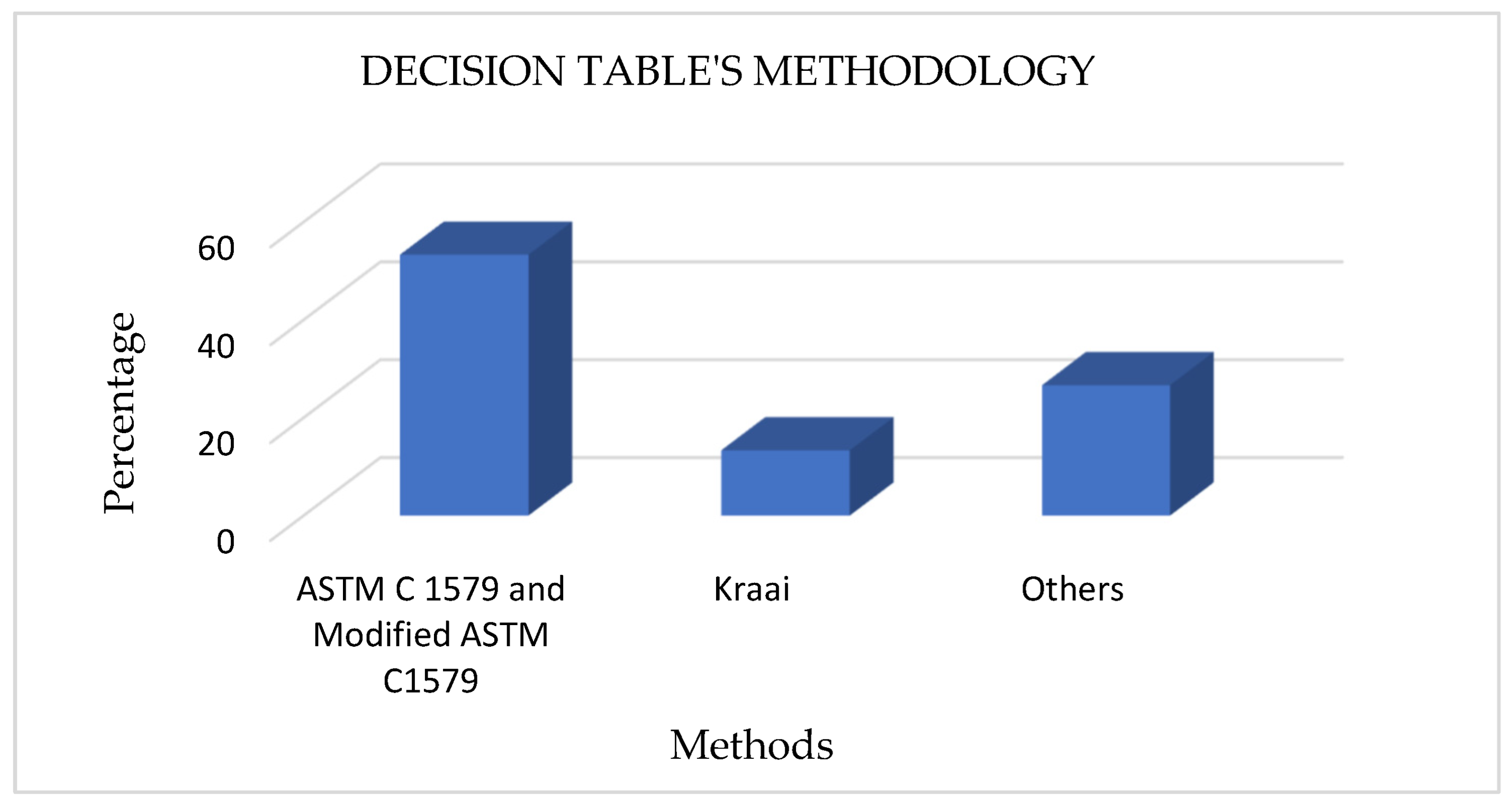
2.2.4. Materials and Methods for Decision Table
3. Decision Table
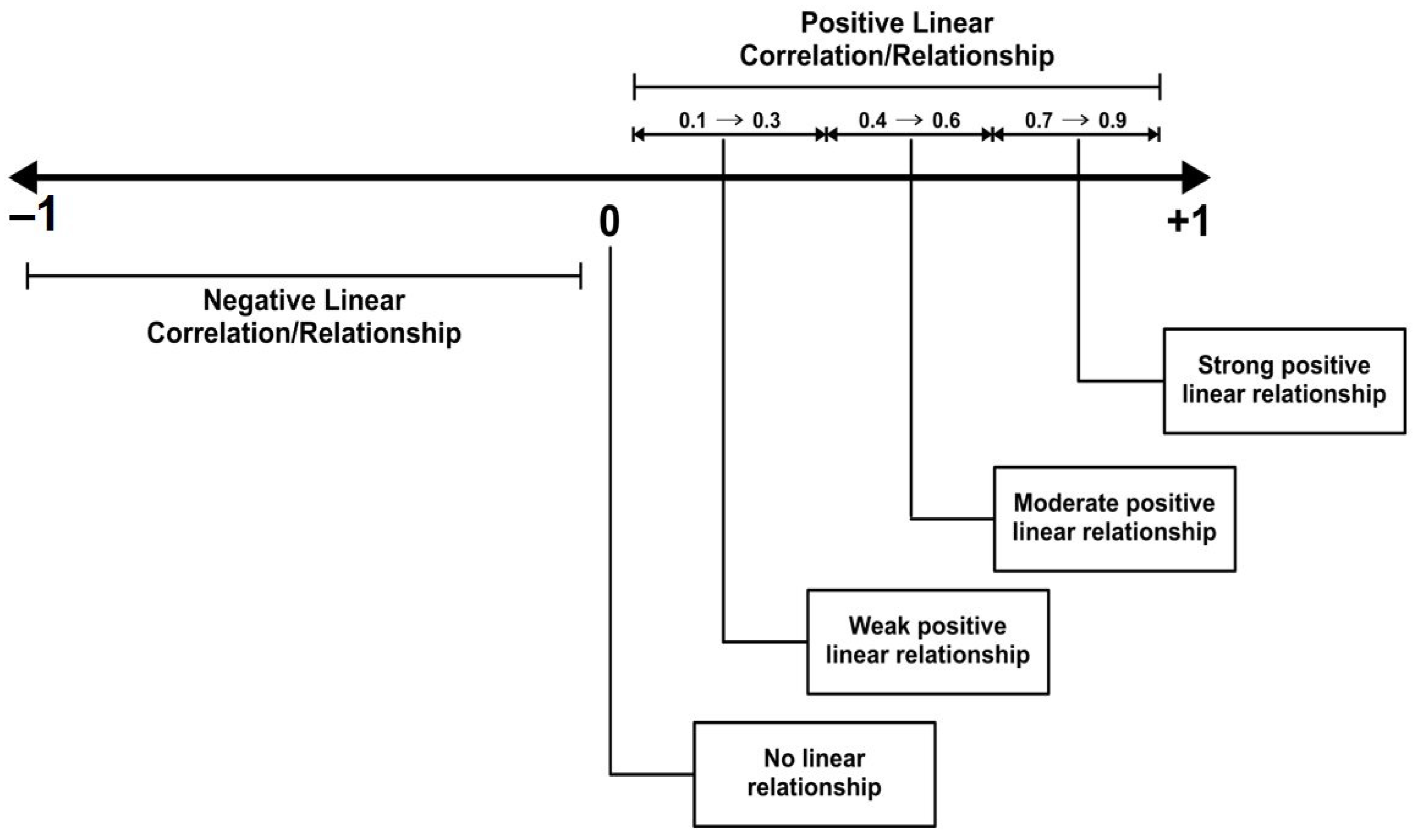
4. Statistical Interpretation
5. Discussion
5.1. Fibre Volume
5.2. Aspect Ratio of Fiber
5.3. Cracking Time
5.4. Type of Fiber
5.5. Limitations and Challenges of Using Fibers in Concrete
6. Future Research Direction
- While a few researchers considered crack initiation time, many neglected it. Future research should take the cracking time of concrete into consideration. This will give more insight into the performance of the additive used for mitigation.
- Steel and bolts have been used to further restrain the ASTM C1579 mold. Future research should consider using fiber-reinforced polymer (FRP) composites since the use of these composites is fast spreading in the construction industry due to their high strength and corrosion-resistant behavior. Therefore, there is a need to understand their effect in enhancing early-age cracking. Furthermore, past researchers primarily considered the crack length, width, and area. Therefore, research in the future should consider estimating the value of the crack depth. Doing this will provide a full description of the crack formed.
- Laboratory studies of constrained plastic shrinkage cracking have been conducted using a variety of techniques, including Kraai, Modified ASTMC 1579, and ASTMC 1579. To validate laboratory results and offer useful guidelines for construction methods, real-world case studies and field applications of fiber-reinforced concrete must be recorded and examined.
- For the most past research, only virgin natural, synthetic, and steel fibers have been used to mitigate plastic shrinkage cracking in concretes. Future research should consider the use of recycled fibers to reduce environmental impact, carbon footprint, and cost (recycled fibers are cheaper compared to virgin fibers).
- The role of fiber-reinforced concrete in capturing and managing microplastics in construction and the built environment should be examined. In particular, it is important to assess how the fibers interact with the concrete when they crack to either retain or release microplastics. This study will shed light on how fiber-reinforced concrete in urban infrastructure affects the environment and how sustainable it is.
7. Conclusions
- Plastic shrinkage cracks in concrete can be partially or completely mitigated by adding steel, synthetic, or natural fibers. Fibers assist in the distribution of environmental loads and improve the ductility of concrete by acting as reinforcements, owing to their tensile strength.
- The inclusion of either hooked-end or recycled tire steel fibers can delay the appearance of cracks when the concrete is in a plastic state. This delay allows the concrete to develop tensile strength, enabling it to withstand harsh environmental conditions and preventing cracking.
- Natural, synthetic, and steel fibers with a greater aspect ratio, longer length (approximately 50 mm), and higher tensile strength outperformed shorter fibers in eliminating plastic shrinkage cracks but also harmed the compressive strength of the concrete because of the high rate of water loss. Because of their increased surface area, they can bridge fractures. Furthermore, their higher tensile strength compared to shorter ones can prevent cracks from widening. The aspect ratio is weakly positively correlated with crack reduction and weakly negatively correlated with compressive strength. In addition, the fiber volume fraction had a greater impact on the aspect ratio for reducing plastic cracking.
- A strong positive relationship existed between the volume fraction of fibers and crack reduction, whereas a strong negative correlation was observed with the compressive strength of concrete. Therefore, increasing the volume percentage of fibers in a concrete matrix minimizes plastic shrinkage cracking but lowers the compressive strength. A volume percentage of no more than 1% of natural, synthetic, and steel fibers is recommended to strike a compromise between plastic shrinkage cracks and compressive strength.
- The type of fiber and characteristics play a significant role in their performance.
- The absence of large data points in the predictive analysis can limit the accuracy of the equations provided. However, it is more accurate when used to predict intermediate data points between the range of the original data points.
Author Contributions
Funding
Data Availability Statement
Conflicts of Interest
Abbreviations
| ASTM | American Society for Testing and Materials (ASTM International) |
| C:F.A:C.A:W | Cement:Fine Aggregate:Coarse Aggregate:Water |
| FRC | Fiber-reinforced Concrete |
| NM | Not Mentioned |
| SP | Superplasticizer |
| Ref | Reference |
| RH | Relative humidity |
| T | Temperature |
| Env. Cond | Environmental condition |
| W | Wind |
| E | Evaporation |
| FA | Fly ash |
| SF | Silica fume |
| OPC | Ordinary Portland cement |
| b/c | Binder to Cement ratio |
| H1 | Fiber with an Aspect Ratio of 55 |
| H2 | Fiber with an Aspect Ratio of 65 |
| H3 | Fiber with an Aspect Ratio of 80 |
References
- Mora-Ruacho, J.; Gettu, R.; Aguado, A. Influence of shrinkage-reducing admixtures on the reduction of plastic shrinkage cracking in concrete. Cem. Concr. Res. 2009, 39, 141–146. [Google Scholar] [CrossRef]
- Cohen, M.D.; Olek, J.; Dolch, W.L. Mechanism of plastic shrinkage cracking in portland cement and portland cement-silica fume paste and mortar. Cem. Concr. Res. 1990, 20, 103–119. [Google Scholar] [CrossRef]
- Padron, I.; Zollo, R.F. Effect of synthetic fibers on volume stability and cracking of portland cement concrete and mortar. Mater. J. 1990, 87, 327–332. [Google Scholar] [CrossRef]
- Singh, M. Coal bottom ash. In Waste and Supplementary Cementitious Materials in Concrete; Woodhead Publishing: Sawston, UK, 2018; pp. 3–50. [Google Scholar] [CrossRef]
- Mindess, S.; Young, F.; Darwin, D. Concrete. In Technical Documents; Prentice Hall: Hoboken, NJ, USA, 2003; p. 585. [Google Scholar]
- Brooks, J.J. Dimensional stability and cracking processes in concrete. In Durability of Concrete and Cement Composites; Woodhead Publishing: Sawston, UK, 2007; pp. 45–85. [Google Scholar] [CrossRef]
- Ghourchian, S.; Wyrzykowski, M.; Plamondon, M.; Lura, P. On the mechanism of plastic shrinkage cracking in fresh cementitious materials. Cem. Concr. Res. 2019, 115, 251–263. [Google Scholar] [CrossRef]
- Almussalam, A.A.; Maslehuddin, M.; Abdul-Waris, M.; Dakhil, F.H.; al-Amoudi, O.S.B. Plastic shrinkage cracking of blended cement concretes in hot environments. Mag. Concr. Res. 1999, 51, 241–246. [Google Scholar] [CrossRef]
- Banthia, N.; Gupta, R. Plastic shrinkage cracking in cementitious repairs and overlays. Mater. Struct. 2009, 42, 567–579. [Google Scholar] [CrossRef]
- Yun, K.-K.; Panov, V.; Kim, S.; Han, S. Plastic shrinkage cracking properties of high-performance shotcrete with supplementary cementitious materials. Eur. J. Environ. Civ. Eng. 2023, 27, 159–173. [Google Scholar] [CrossRef]
- Golewski, G.L. The phenomenon of cracking in cement concretes and reinforced concrete structures: The mechanism of cracks formation, causes of their initiation, types and places of occurrence, and Methods of Detection—A review. Buildings 2023, 13, 765. [Google Scholar] [CrossRef]
- Rodriguez, O.G. Influence of Cracks on Chloride Ingress into Concrete. ACI Mater. J. 2003, 100, 120–126. [Google Scholar] [CrossRef]
- Woodson, R.D. Concrete Structures: Protection, Repair and Rehabilitation; Elsevier: Amsterdam, The Netherlands, 2009. [Google Scholar]
- El-Reedy, M.A. Onshore Structural Design Calculations: Power Plant and Energy Processing Facilities; Elsevier: Amsterdam, The Netherlands, 2016. [Google Scholar]
- Day, R.; Clarke, J.M. Plastic and thermal cracking. Adv. Concr. Technol. 2003, 1, 3–17. [Google Scholar] [CrossRef]
- Leemann, A.; Nygaard, P.V.; Lura, P. Impact of admixtures on the plastic shrinkage cracking of self-compacting concrete. Cem. Concr. Compos. 2014, 46, 1–7. [Google Scholar] [CrossRef]
- Lura, P.; Pease, B.; Mazzotta, G.B.; Rajabipour, F.; Weiss, J. Influence of Shrinkage-Reducing admixtures on development of plastic shrinkage cracks. ACI Mater. J. 2007, 104, 187–194. [Google Scholar] [CrossRef]
- ASTM C1579-06; Standard Test Method for Evaluating Plastic Shrinkage Cracking of Restrained Fiber Reinforced Concrete (Using a Steel Form Insert). ASTM International: West Conshohocken, PA, USA, 2006.
- ASTM C1579-13; Standard Test Method for Evaluating Plastic Shrinkage Cracking of Restrained Fiber Reinforced Concrete (Using a Steel Form Insert). ASTM International: West Conshohocken, PA, USA, 2013.
- Wu, L.; Farzadnia, N.; Shi, C.; Zhang, Z.; Wang, H. Autogenous Shrinkage of High Performance Concrete: A Review. Constr. Build. Mater. 2017, 149, 62–75. [Google Scholar] [CrossRef]
- Lura, P.; Jensen, O.M.; van Breugel, K. Autogenous Shrinkage in High-Performance Cement Paste: An Evaluation of Basic Mechanisms. Cem. Concr. Res. 2003, 33, 223–232. [Google Scholar] [CrossRef]
- Ballekere Kumarappa, D.; Peethamparan, S.; Ngami, M. Autogenous Shrinkage of Alkali Activated Slag Mortars: Basic Mechanisms and Mitigation Methods. Cem. Concr. Res. 2018, 109, 1–9. [Google Scholar] [CrossRef]
- Williams, A.; Markandeya, A.; Stetsko, Y.; Riding, K.; Zayed, A. Cracking Potential and Temperature Sensitivity of Metakaolin Concrete. Constr. Build. Mater. 2016, 120, 172–180. [Google Scholar] [CrossRef]
- Tang, S.; Huang, D.; He, Z. A Review of Autogenous Shrinkage Models of Concrete. J. Build. Eng. 2021, 44, 103412. [Google Scholar] [CrossRef]
- Ghanem, H.; Ramadan, R.; Khatib, J.; Elkordi, A. A Review on Chemical and Autogenous Shrinkage of Cementitious Systems. Materials 2024, 17, 283. [Google Scholar] [CrossRef]
- Wang, D.; Shi, C.; Wu, Z.; Xiao, J.; Huang, Z.; Fang, Z. A Review on Ultra High Performance Concrete: Part II. Hydration, Microstructure and Properties. Constr. Build. Mater. 2015, 96, 368–377. [Google Scholar] [CrossRef]
- van Breugel, K.; van Tuan, N. Autogenous Shrinkage of HPC and Ways to Mitigate It. Key Eng. Mater. 2014, 629–630, 3–20. [Google Scholar] [CrossRef]
- Wang, L.; He, T.; Zhou, Y.; Tang, S.; Tan, J.; Liu, Z.; Su, J. The Influence of Fiber Type and Length on the Cracking Resistance, Durability and Pore Structure of Face Slab Concrete. Constr. Build. Mater. 2021, 282, 122706. [Google Scholar] [CrossRef]
- Akcay, B.; Tasdemir, M.A. Autogenous Shrinkage, Pozzolanic Activity and Mechanical Properties of Metakaolin Blended Cementitious Materials. KSCE J. Civ. Civ. Eng. 2019, 23, 4727–4734. [Google Scholar] [CrossRef]
- Wyrzykowski, M.; Assmann, A.; Hesse, C.; Lura, P. Microstructure Development and Autogenous Shrinkage of Mortars with C-S-H Seeding and Internal Curing. Cem. Concr. Res. 2020, 129, 105967. [Google Scholar] [CrossRef]
- Wang, L.; Jin, M.; Wu, Y.; Zhou, Y.; Tang, S. Hydration, Shrinkage, Pore Structure and Fractal Dimension of Silica Fume Modified Low Heat Portland Cement-Based Materials. Constr. Build. Mater. 2021, 272, 121952. [Google Scholar] [CrossRef]
- Wang, L.; Guo, F.; Lin, Y.; Yang, H.; Tang, S.W. Comparison between the Effects of Phosphorous Slag and Fly Ash on the C-S-H Structure, Long-Term Hydration Heat and Volume Deformation of Cement-Based Materials. Constr. Build. Mater. 2020, 250, 118807. [Google Scholar] [CrossRef]
- Ma, Y.; Ye, G. The Shrinkage of Alkali Activated Fly Ash. Cem. Concr. Res. 2015, 68, 75–82. [Google Scholar] [CrossRef]
- Huang, D.; Chen, P.; Peng, H.; Yang, Y.; Yuan, Q.; Su, M. A Review and Comparison Study on Drying Shrinkage Prediction between Alkali-Activated Fly Ash/Slag and Ordinary Portland Cement. Constr. Build. Mater. 2021, 305, 124760. [Google Scholar] [CrossRef]
- Henkensiefken, R.; Bentz, D.; Nantung, T.; Weiss, J. Volume Change and Cracking in Internally Cured Mixtures Made with Saturated Lightweight Aggregate under Sealed and Unsealed Conditions. Cem. Concr. Compos. 2009, 31, 427–437. [Google Scholar] [CrossRef]
- Mastali, M.; Kinnunen, P.; Dalvand, A.; Mohammadi Firouz, R.; Illikainen, M. Drying Shrinkage in Alkali-Activated Binders—A Critical Review. Constr. Build. Mater. 2018, 190, 533–550. [Google Scholar] [CrossRef]
- Tran, N.P.; Gunasekara, C.; Law, D.W.; Houshyar, S.; Setunge, S.; Cwirzen, A. A Critical Review on Drying Shrinkage Mitigation Strategies in Cement-Based Materials. J. Build. Eng. 2021, 38, 102210. [Google Scholar] [CrossRef]
- Mao, Y.; Liu, J.; Shi, C. Autogenous Shrinkage and Drying Shrinkage of Recycled Aggregate Concrete: A Review. J. Clean. Prod. 2021, 295, 126435. [Google Scholar] [CrossRef]
- Wongkeo, W.; Thongsanitgarn, P.; Chaipanich, A. Compressive Strength and Drying Shrinkage of Fly Ash-Bottom Ash-Silica Fume Multi-Blended Cement Mortars. Mater. Des. 2012, 36, 655–662. [Google Scholar] [CrossRef]
- Azarhomayun, F.; Haji, M.; Kioumarsi, M.; Shekarchi, M. Effect of Calcium Stearate and Aluminum Powder on Free and Restrained Drying Shrinkage, Crack Characteristic and Mechanical Properties of Concrete. Cem. Concr. Compos. 2022, 125, 104276. [Google Scholar] [CrossRef]
- Yang, J.; Wang, Q.; Zhou, Y. Influence of Curing Time on the Drying Shrinkage of Concretes with Different Binders and Water-to-Binder Ratios. Adv. Mater. Sci. Eng. 2017, 2017, 2695435. [Google Scholar] [CrossRef]
- Guerini, V.; Conforti, A.; Plizzari, G.; Kawashima, S. Influence of steel and Macro-Synthetic fibers on concrete properties. Fibers 2018, 6, 47. [Google Scholar] [CrossRef]
- Chalioris, C.E. Analytical approach for the evaluation of minimum fibre factor required for steel fibrous concrete beams under combined shear and flexure. Constr. Build. Mater. 2013, 43, 317–336. [Google Scholar] [CrossRef]
- Slater, E.; Moni, M.; Alam, M.S. Predicting the shear strength of steel fiber reinforced concrete beams. Constr. Build. Mater. 2012, 26, 423–436. [Google Scholar] [CrossRef]
- Ding, Y.; You, Z.; Jalali, S. The composite effect of steel fibres and stirrups on the shear behaviour of beams using self-consolidating concrete. Eng. Struct. 2011, 33, 107–117. [Google Scholar] [CrossRef]
- Sorelli, L.G.; Meda, A.; Plizzari, G.A. Steel fiber concrete slabs on ground: A structural matter. ACI Struct. J. 2006, 103, 551–558. [Google Scholar] [CrossRef]
- Kirsanov, A.; Stolyarov, O. Mechanical properties of synthetic fibers applied to concrete reinforcement. Mag. Civ. Eng. 2018, 80, 15–23. [Google Scholar] [CrossRef]
- Zhao, C.; Wang, Z.; Zhu, Z.; Guo, Q.; Wu, X.; Zhao, R. Research on different types of fiber reinforced concrete in recent years: An overview. Constr. Build. Mater. 2023, 365, 130075. [Google Scholar] [CrossRef]
- Sadrinejad, I.; Madandoust, R.; Ranjbar, M.M. The mechanical and durability properties of concrete containing hybrid synthetic fibers. Constr. Build. Mater. 2018, 178, 72–82. [Google Scholar] [CrossRef]
- Elfaleh, I.; Abbassi, F.; Habibi, M.; Ahmad, F.; Guedri, M.; Nasri, M.; Girard, C. A comprehensive review of natural fibers and their composites: An eco-friendly alternative to conventional materials. Results Eng. 2023, 19, 101271. [Google Scholar] [CrossRef]
- Singh, M.K.; Tewari, R.; Zafar, S.; Rangappa, S.M.; Siengchin, S. A comprehensive review of various factors for application feasibility of natural fiber-reinforced polymer composites. Results Mater. 2023, 17, 100355. [Google Scholar] [CrossRef]
- Tahir, P.M.; Ahmed, A.B.; Saifulazry, S.O.A.; Ahmed, Z. Retting Process of Some Bast Plant Fibres and Its Effect on Fibre Quality: A Review. BioResources 2011, 6, 5260–5281. [Google Scholar] [CrossRef]
- May-Pat, A.; Valadez-González, A.; Herrera-Franco, P.J. Effect of Fiber Surface Treatments on the Essential Work of Fracture of HDPE-Continuous Henequen Fiber-Reinforced Composites. Polym. Test. 2013, 32, 1114–1122. [Google Scholar] [CrossRef]
- Navaratnam, S.; Selvaranjan, K.; Jayasooriya, D.; Rajeev, P.; Sanjayan, J. Applications of natural and synthetic fiber reinforced polymer in infrastructure: A suitability assessment. J. Build. Eng. 2023, 66, 105835. [Google Scholar] [CrossRef]
- Kouta, N.; Saliba, J.; Saiyouri, N. Effect of flax fibers on early age shrinkage and cracking of earth concrete. Constr. Build. Mater. 2020, 254, 119315. [Google Scholar] [CrossRef]
- Guo, A.; Sun, Z.; Satyavolu, J. Impact of modified kenaf fibers on shrinkage and cracking of cement pastes. Constr. Build. Mater. 2020, 264, 120230. [Google Scholar] [CrossRef]
- Choi, S.; Panov, V.; Han, S.; Yun, K.-K. Natural fiber-reinforced shotcrete mixture: Quantitative assessment of the impact of fiber on fresh and plastic shrinkage cracking properties. Constr. Build. Mater. 2023, 366, 130032. [Google Scholar] [CrossRef]
- Hwang, C.; Tran, V.-A.; Hong, J.-W.; Hsieh, Y.-C. Effects of short coconut fiber on the mechanical properties, plastic cracking behavior, and impact resistance of cementitious composites. Constr. Build. Mater. 2016, 127, 984–992. [Google Scholar] [CrossRef]
- Othman, M.H. Bamboo Fiber as Fillers for Polypropylene-Nanoclay via Injection Molding. In Encyclopedia of Renewable and Sustainable Materials; Elsevier: Amsterdam, The Netherlands, 2020. [Google Scholar] [CrossRef]
- Juárez, C.G.; Fajardo, G.; Monroy, S.; Durán-Herrera, A.; Valdez, P.; Magniont, C. Comparative study between natural and PVA fibers to reduce plastic shrinkage cracking in cement-based composite. Constr. Build. Mater. 2015, 91, 164–170. [Google Scholar] [CrossRef]
- Özaşik, N.; Eren, Ö. Influence of recycled polyethylene terephthalate fibres on plastic shrinkage and mechanical properties of concrete. Front. Struct. Civ. Eng. 2022, 16, 792–802. [Google Scholar] [CrossRef]
- Xiao, K.T.; Li, J.Z.; Hua, Y. Study of crack resistance property of polyvinyl alcohol fiber reinforced concrete. Adv. Mater. Res. 2011, 287–290, 178–182. [Google Scholar] [CrossRef]
- Shao, Y.; Mirmiran, A. Control of plastic shrinkage cracking of concrete with carbon fiber-reinforced polymer grids. J. Mater. Civ. Eng. 2007, 19, 441–444. [Google Scholar] [CrossRef]
- Rahmani, T.; Kiani, B.; Bakhshi, M.; Shekarchizadeh, M. Application of Different Fibers to Reduce Plastic Shrinkage Cracking of Concrete; Rilem bookseries; Springer: Dordrecht, The Netherlands, 2012; pp. 635–642. [Google Scholar] [CrossRef]
- Alshammari, T.O.; Pilakoutas, K.; Guadagnini, M. Performance of manufactured and recycled steel fibres in restraining concrete plastic shrinkage cracks. Materials 2023, 16, 713. [Google Scholar] [CrossRef] [PubMed]
- Su, P.; Li, M.; Dai, Q.; Wang, J. Mechanical and durability performance of concrete with recycled tire steel fibers. Constr. Build. Mater. 2023, 394, 132287. [Google Scholar] [CrossRef]
- Abbass, W.; Khan, M.I.; Mourad, S. Evaluation of mechanical properties of steel fiber reinforced concrete with different strengths of concrete. Constr. Build. Mater. 2018, 168, 556–569. [Google Scholar] [CrossRef]
- Rahman, R.; Putra, S.Z.F.S. Tensile properties of natural and synthetic fiber-reinforced polymer composites. In Mechanical and Physical Testing of Biocomposites, Fibre-Reinforced Composites and Hybrid Composites; Woodhead Publishing: Sawston, UK, 2019; pp. 81–102. [Google Scholar] [CrossRef]
- Thakur, V.K.; Thakur, M.K.; Pappu, A. (Eds.) Hybrid Polymer Composite Materials: Applications; Woodhead Publishing: Sawston, UK, 2017. [Google Scholar]
- Cavaco-Paulo, A.; Gübitz, G. Textile Processing with Enzymes; Taylor & Francis: London, UK, 2003. [Google Scholar] [CrossRef]
- Silva, C.; Cavaco-Paulo, A. Biotransformations in synthetic fibres. Biocatal. Biotransform. 2008, 26, 350–356. [Google Scholar] [CrossRef]
- Klyuyev, A.V.; Sopin, D.M.; Netrebenko, A.V.; Казлитин, C.A. Heavy loaded floors based on fine-grained fiber concrete. Mag. Civ. Eng. 2013, 38, 7–14. [Google Scholar] [CrossRef]
- Yoo, D.Y.; Yoon, Y.S. A review on structural behavior, design, and application of ultra-high-performance fiber-reinforced concrete. Int. J. Concr. Struct. Mater. 2016, 10, 125–142. [Google Scholar] [CrossRef]
- Alani, A.M.; Beckett, D. Mechanical properties of a large scale synthetic fibre reinforced concrete ground slab. Constr. Build. Mater. 2013, 41, 335–344. [Google Scholar] [CrossRef]
- Cappitelli, F.; Sorlini, C. Microorganisms attack synthetic polymers in items representing our cultural heritage. Appl. Environ. Microbiol. 2008, 74, 564–569. [Google Scholar] [CrossRef] [PubMed]
- Ahmad, J.; Zhou, Z. Mechanical Properties of Natural as well as Synthetic Fiber Reinforced Concrete: A Review. Constr. Build. Mater. 2022, 333, 127353. [Google Scholar] [CrossRef]
- Alwesabi, E.A.H.; Bakar, B.H.A.; Alshaikh, I.M.H.; Zeyad, A.M.; Altheeb, A.; Alghamdi, H. Experimental investigation on fracture characteristics of plain and rubberized concrete containing hybrid steel-polypropylene fiber. Structures 2021, 33, 4421–4432. [Google Scholar] [CrossRef]
- Gong, C.; Kang, L.; Liu, L.; Lei, M.; Ding, W.; Yang, Z. A novel prediction model of packing density for single and hybrid steel fiber-aggregate mixtures. Powder Technol. 2023, 418, 118295. [Google Scholar] [CrossRef]
- Aslani, F.; Nejadi, S. Creep and Shrinkage of Self-Compacting Concrete with and without Fibers. J. Adv. Concr. Technol. 2013, 11, 251–265. [Google Scholar] [CrossRef]
- Grzymski, F.; Musiał, M.; Trapko, T. Mechanical properties of fibre reinforced concrete with recycled fibres. Constr. Build. Mater. 2019, 198, 323–331. [Google Scholar] [CrossRef]
- Zhang, P.; Wang, C.; Wu, C.; Guo, Y.; Li, Y.; Guo, J. A review on the properties of concrete reinforced with recycled steel fiber from waste tires. Rev. Adv. Mater. Sci. 2022, 61, 276–291. [Google Scholar] [CrossRef]
- Revuelta, D.; Carballosa, P.; García Calvo, J.L.; Pedrosa, F. Residual Strength and Drying Behavior of Concrete Reinforced with Recycled Steel Fiber from Tires. Materials 2021, 14, 6111. [Google Scholar] [CrossRef]
- Bernstad Saraiva, A.; Pacheco, E.B.A.V.; Gomes, G.M.; Visconte, L.L.Y.; Bernardo, C.A.; Simões, C.L.; Soares, A.G. Comparative Lifecycle Assessment of Mango Packaging Made from a Polyethylene/Natural Fiber-Composite and from Cardboard Material. J. Clean. Prod. 2016, 139, 1168–1180. [Google Scholar] [CrossRef]
- Pegoretti, T.d.S.; Mathieux, F.; Evrard, D.; Brissaud, D.; de França Arruda, J.R. Use of Recycled Natural Fibres in Industrial Products: A Comparative LCA Case Study on Acoustic Components in the Brazilian Automotive Sector. Resour. Conserv. Recycl. 2014, 84, 1–14. [Google Scholar] [CrossRef]
- Gonzalez, V.; Lou, X.; Chi, T. Evaluating Environmental Impact of Natural and Synthetic Fibers: A Life Cycle Assessment Approach. Sustainability 2023, 15, 7670. [Google Scholar] [CrossRef]
- Mansor, M.R.; Mastura, M.T.; Sapuan, S.M.; Zainudin, A.Z. The Environmental Impact of Natural Fiber Composites through Life Cycle Assessment Analysis. In Durability and Life Prediction in Biocomposites, Fibre-Reinforced Composites and Hybrid Composites; Elsevier: Amsterdam, The Netherlands, 2019; pp. 257–285. [Google Scholar]
- Adekomaya, O.; Jamiru, T.; Sadiku, R.; Huan, Z. Negative Impact from the Application of Natural Fibers. J. Clean. Prod. 2017, 143, 843–846. [Google Scholar] [CrossRef]
- Moazzem, S.; Crossin, E.; Daver, F.; Wang, L. Assessing Environmental Impact Reduction Opportunities through Life Cycle Assessment of Apparel Products. Sustain. Prod. Consum. 2021, 28, 663–674. [Google Scholar] [CrossRef]
- Bhalla, K.; Kumar, T.; Rangaswamy, J. An Integrated Rural Development Model Based on Comprehensive Life-Cycle Assessment (LCA) of Khadi-Handloom Industry in Rural India. Procedia CIRP 2018, 69, 493–498. [Google Scholar] [CrossRef]
- Munasinghe, P.; Druckman, A.; Dissanayake, D.G.K. A Systematic Review of the Life Cycle Inventory of Clothing. J. Clean. Prod. 2021, 320, 128852. [Google Scholar] [CrossRef]
- Barcelos, S.M.B.D.; Salvador, R.; Guedes, M.d.G.; de Francisco, A.C. Opportunities for Improving the Environmental Profile of Silk Cocoon Production under Brazilian Conditions. Sustainability 2020, 12, 3214. [Google Scholar] [CrossRef]
- Astudillo, M.F.; Thalwitz, G.; Vollrath, F. Life Cycle Assessment of Indian Silk. J. Clean. Prod. 2014, 81, 158–167. [Google Scholar] [CrossRef]
- Palacios-Mateo, C.; van der Meer, Y.; Seide, G. Analysis of the Polyester Clothing Value Chain to Identify Key Intervention Points for Sustainability. Environ. Sci. Eur. 2021, 33, 2. [Google Scholar] [CrossRef]
- Borrion, A.L.; Khraisheh, M.; Benyahia, F. Environmental Life Cycle Impact Assessment of Gas-to-Liquid Processes. In Proceedings of the 3rd Gas Processing Symposium, Doha, Qatar, 5–7 March 2012; pp. 71–77. [Google Scholar] [CrossRef]
- Singh, R.P.; Mishra, S.; Das, A.P. Synthetic Microfibers: Pollution Toxicity and Remediation. Chemosphere 2020, 257, 127199. [Google Scholar] [CrossRef]
- Holappa, L. A General Vision for Reduction of Energy Consumption and CO2 Emissions from the Steel Industry. Metals 2020, 10, 1117. [Google Scholar] [CrossRef]
- Burchart-Korol, D. Life Cycle Assessment of Steel Production in Poland: A Case Study. J. Clean. Prod. 2013, 54, 235–243. [Google Scholar] [CrossRef]
- Liew, K.M.; Akbar, A. The Recent Progress of Recycled Steel Fiber Reinforced Concrete. Constr. Build. Mater. 2020, 232, 117232. [Google Scholar] [CrossRef]
- Zanetta-Colombo, N.C.; Fleming, Z.L.; Gayo, E.M.; Manzano, C.A.; Panagi, M.; Valdés, J.; Siegmund, A. Impact of Mining on the Metal Content of Dust in Indigenous Villages of Northern Chile. Env. Environ. Int. 2022, 169, 107490. [Google Scholar] [CrossRef] [PubMed]
- Agboola, O.; Babatunde, D.E.; Isaac Fayomi, O.S.; Sadiku, E.R.; Popoola, P.; Moropeng, L.; Yahaya, A.; Mamudu, O.A. A Review on the Impact of Mining Operation: Monitoring, Assessment and Management. Results Eng. 2020, 8, 100181. [Google Scholar] [CrossRef]
- Worlanyo, A.S.; Jiangfeng, L. Evaluating the Environmental and Economic Impact of Mining for Post-Mined Land Restoration and Land-Use: A Review. J. Environ. Manag. 2021, 279, 111623. [Google Scholar] [CrossRef] [PubMed]
- Kim, J.; Son, M.; Park, J.; Kim, J. Optimized Rotary Hearth Furnace Utilization with Blast Furnace and Electric Arc Furnace: Techno-Economics, CO2 Reduction. Fuel Process. Technol. 2022, 237, 107450. [Google Scholar] [CrossRef]
- Babich, A. Blast Furnace Injection for Minimizing the Coke Rate and CO2 Emissions. Ironmak. Steelmak. 2021, 48, 728–741. [Google Scholar] [CrossRef]
- Perpiñán, J.; Peña, B.; Bailera, M.; Eveloy, V.; Kannan, P.; Raj, A.; Lisbona, P.; Romeo, L.M. Integration of Carbon Capture Technologies in Blast Furnace Based Steel Making: A Comprehensive and Systematic Review. Fuel 2023, 336, 127074. [Google Scholar] [CrossRef]
- Shi, X.; Park, P.; Rew, Y.; Huang, K.; Sim, C. Constitutive Behaviors of Steel Fiber Reinforced Concrete under Uniaxial Compression and Tension. Constr. Build. Mater. 2020, 233, 117316. [Google Scholar] [CrossRef]
- Chen, H.; Yang, J.; Chen, X. A Convolution-Based Deep Learning Approach for Estimating Compressive Strength of Fiber Reinforced Concrete at Elevated Temperatures. Constr. Build. Mater. 2021, 313, 125437. [Google Scholar] [CrossRef]
- Chung, K.L.; Wang, L.; Ghannam, M.; Guan, M.; Luo, J. Prediction of Concrete Compressive Strength Based on Early-Age Effective Conductivity Measurement. J. Build. Eng. 2021, 35, 101998. [Google Scholar] [CrossRef]
- Neville, A. Properties of Concrete; Wiley: Hoboken, NJ, USA, 1968. [Google Scholar]
- Mehta, P.; Monteiro, P.J.M. Concrete: Microstructure, Properties, and Materials; McGraw-Hill Education: New York, NY, USA, 2005. [Google Scholar]
- Vu, C.-C.; Plé, O.; Weiss, J.; Amitrano, D. Revisiting the concept of characteristic compressive strength of concrete. Constr. Build. Mater. 2020, 263, 120126. [Google Scholar] [CrossRef]
- Akinyele, J.O.; Folorunsho, A.B. The Use of SEM/EDX Analysis to Investigate the Pore Effect on the Mechanical Properties of some Selected Tropical Hardwoods. Int. J. Eng. Res. Afr. 2021, 56, 64–76. [Google Scholar] [CrossRef]
- Akinyele, J.O.; Folorunsho, A.B.; Igba, U.T.; Omotainse, P.O.; Labiran, J.O. The effect of wood microstructure on the mechanical properties of some selected tropical hardwood species used in construction. In Current Perspectives and New Directions in Mechanics, Modelling and Design of Structural Systems, Proceedings of the 8th International Conference on Structural Engineering, Mechanics and Computation, Cape Town, South Africa, 5–7 September 2022; CRC Press: Boca Raton, FL, USA, 2022; pp. 591–592. [Google Scholar] [CrossRef]
- Chia, R.W.; Lee, J.Y.; Jang, J.; Cha, J. Errors and recommended practices that should be identified to reduce suspected concentrations of microplastics in soil and groundwater: A review. Environ. Technol. Innov. 2022, 28, 102933. [Google Scholar] [CrossRef]
- Chia, R.W.; Lee, J.Y.; Cha, J.; Rodríguez-Seijo, A. Methods of soil sampling for microplastic analysis: A review. Environ. Chem. Lett. 2024, 22, 227–238. [Google Scholar] [CrossRef]
- Srivani, G.; Mohan, U.V. Study on strength properties of concrete by partial replacement of cement with sugarcane bagasse ash and coarse aggregate with coconut shells. Mater. Today Proc. 2023. [Google Scholar] [CrossRef]
- Chindasiriphan, P.; Meenyut, B.; Orasutthikul, S.; Jongvivatsakul, P.; Tangchirapat, W. Influences of high-volume coal bottom ash as cement and fine aggregate replacements on strength and heat evolution of eco-friendly high-strength concrete. J. Build. Eng. 2023, 65, 105791. [Google Scholar] [CrossRef]
- Banthia, N.; Soleimani, S.M. Flexural response of hybrid fiber-reinforced cementitious composites. ACI Mater. J. 2005, 102, 382–389. [Google Scholar] [CrossRef]
- Sultana, I.; Islam, G.M.S. Potential of ladle furnace slag as supplementary cementitious material in concrete. Case Stud. Constr. Mater. 2023, 18, e02141. [Google Scholar] [CrossRef]
- Salem, S.; Hamdy, Y.; Abdelraouf, E.-S.; Shazly, M. Towards sustainable concrete: Cement replacement using Egyptian cornstalk ash. Case Stud. Constr. Mater. 2022, 17, e01193. [Google Scholar] [CrossRef]
- Markin, S.; Mechtcherine, V. Quantification of plastic shrinkage and plastic shrinkage cracking of the 3D printable concretes using 2D digital image correlation. Cem. Concr. Compos. 2023, 139, 105050. [Google Scholar] [CrossRef]
- Bolander, J.E.; Roghani, H.; Nanni, A. Early-age cracking in concrete slabs with FRP reinforcement. In Life-Cycle of Structures and Infrastructure Systems; CRC Press: Boca Raton, FL, USA, 2023; pp. 1233–1240. [Google Scholar] [CrossRef]
- Roghani, H.; Nanni, A.; Bolander, J.E. Early-Age Cracking Behavior of Concrete Slabs with GFRP Reinforcement. Materials 2023, 16, 5489. [Google Scholar] [CrossRef] [PubMed]
- Nuaklong, P.; Jongvivatsakul, P.; Phanupornprapong, V.; Intarasoontron, J.; Shahzadi, H.; Pungrasmi, W.; Thaiboonrod, S.; Likitlersuang, S. Self-repairing of shrinkage crack in mortar containing microencapsulated bacterial spores. J. Mater. Res. Technol. 2023, 23, 3441–3454. [Google Scholar] [CrossRef]
- Arulmoly, B.; Konthesingha, C.; Nanayakkara, S. Plastic settlement and hardened state assessments of manufactured sand made concrete for varying microfine levels. Struct. Concr. 2022, 24, 3969–3989. [Google Scholar] [CrossRef]
- Alshammari, T.O.; Guadagnini, M.; Pilakoutas, K. The effect of harsh environmental conditions on concrete plastic shrinkage cracks: Case Study Saudi Arabia. Materials 2022, 15, 8622. [Google Scholar] [CrossRef]
- Boshoff, W.P.; Combrinck, R. Modelling the severity of plastic shrinkage cracking in concrete. Cem. Concr. Res. 2013, 48, 34–39. [Google Scholar] [CrossRef]
- Combrinck, R.; Steyl, L.; Boshoff, W.P. Interaction between settlement and shrinkage cracking in plastic concrete. Constr. Build. Mater. 2018, 185, 1–11. [Google Scholar] [CrossRef]
- Kraai, P.P. A proposed test to determine the cracking potential due to drying shrinkage of concrete. Concr. Constr. 1985, 30, 775–778. [Google Scholar]
- Balaguru, P. Contribution of fibers to crack reduction of cement composites during the initial and final setting period. Mater. J. 1994, 91, 280–288. [Google Scholar] [CrossRef]
- Soroushian, P.; Mirza, F.; Alhozajiny, A. Plastic shrinkage cracking of polypropylene fiber reinforced concrete. Mater. J. 1993, 92, 553–560. [Google Scholar] [CrossRef]
- Eren, Ö.; Marar, K. Effect of steel fibers on plastic shrinkage cracking of normal and high strength concretes. Mater. Res. 2010, 13, 135–141. [Google Scholar] [CrossRef]
- Bertelsen, I.M.G.; Ottosen, L.M.; Fischer, G. Influence of fibre characteristics on plastic shrinkage cracking in cement-based materials: A review. Constr. Build. Mater. 2020, 230, 116769. [Google Scholar] [CrossRef]
- Amaguaña, M.; Guamán, L.; Gómez, N.B.Y.; Khorami, M.; Calvo, M.I.; Albuja-Sánchez, J. Test Method for Studying the Shrinkage Effect under Controlled Environmental Conditions for Concrete Reinforced with Coconut Fibres. Materials 2023, 16, 3247. [Google Scholar] [CrossRef]
- Borg, R.P.; Baldacchino, O.; Ferrara, L. Early age performance and mechanical characteristics of recycled PET fibre reinforced concrete. Constr. Build. Mater. 2016, 108, 29–47. [Google Scholar] [CrossRef]
- Mazzoli, A.; Monosi, S.; Plescia, E.S. Evaluation of the early-age-shrinkage of Fiber Reinforced Concrete (FRC) using image analysis methods. Constr. Build. Mater. 2015, 101, 596–601. [Google Scholar] [CrossRef]
- Fenton, C.T. Testing Plastic Shrinkage and Cracking in Concrete with an Improved Digital Image Correlation Method; Stellenbosch University: Stellenbosch, South Africa, 2023. [Google Scholar]
- Dabhade, P.S.; Shinde, A.R.; Jadhav, P.A.; More, M.M.; Kadam, V.S.; Patil, A.S. An Investigation of Plastic Shrinkage Cracks in Concrete Containing Different Fibers. Available online: https://www.researchgate.net/profile/Vidyanand_Kadam/publication/374673862_An_investigation_of_plastic_shrinkage_cracks_in_concrete_containing_different_fibers/links/65290dae1a05311a23fbbe0f/An-investigation-of-plastic-shrinkage-cracks-in-concrete-containing-different-fibers.pdf. (accessed on 10 June 2024).
- Shen, D.; Liu, X.; Zeng, X.; Zhao, X.; Jiang, G. Effect of polypropylene plastic fibers length on cracking resistance of high performance concrete at early age. Constr. Build. Mater. 2020, 244, 117874. [Google Scholar] [CrossRef]
- Pan, Z.; Zhu, Y.; Zhang, D.; Chen, N.; Yang, Y.; Cai, X. Effect of expansive agents on the workability, crack resistance and durability of shrinkage-compensating concrete with low contents of fibers. Constr. Build. Mater. 2020, 259, 119768. [Google Scholar] [CrossRef]
- Tioua, T.; Kriker, A.; Barluenga, G.; Palomar, I. Influence of date palm fiber and shrinkage reducing admixture on self-compacting concrete performance at early age in hot-dry environment. Constr. Build. Mater. 2017, 154, 721–733. [Google Scholar] [CrossRef]
- Sivakumar, A.; Santhanam, M. A quantitative study on the plastic shrinkage cracking in high strength hybrid fibre reinforced concrete. Cem. Concr. Comp. 2007, 29, 575–581. [Google Scholar] [CrossRef]
- Sayahi, F.; Emborg, M.; Hedlund, H.; Cwirzen, A. Effect of steel fibres extracted from recycled tyres on plastic shrinkage cracking in self-compacting concrete. Mag. Concr. Res. 2021, 73, 1270–1282. [Google Scholar] [CrossRef]
- Paul, S.; van Zijl, G.; Savija, B. Effect of fibers on durability of concrete: A practical review. Materials 2020, 13, 4562. [Google Scholar] [CrossRef]
- More, F.M.D.S.; Subramanian, S.S. Impact of Fibres on the Mechanical and Durable Behaviour of Fibre-Reinforced Concrete. Buildings 2022, 12, 1436. [Google Scholar] [CrossRef]
- Wongtanakitcharoen, T. Effect of Randomly Distributed Fibers on Plastic Shrinkage Cracking of Cement Composites. Ph.D. Thesis, University of Michigan, Ann Arbor, MI, USA, 2005. [Google Scholar]
- Moelich, G.M.; Kruger, P.J.; Combrinck, R. Mitigating Early Age Cracking in 3D Printed Concrete Using Fibres, Superabsorbent Polymers, Shrinkage Reducing Admixtures, B-CSA Cement and Curing Measures. Cem. Concr. Res. 2022, 159, 106862. [Google Scholar] [CrossRef]
- Jamshaid, H.; Mishra, R.K.; Raza, A.; Hussain, U.; Rahman, M.d.L.; Nazari, S.; Chandan, V.; Muller, M.; Choteborsky, R. Natural Cellulosic Fiber Reinforced Concrete: Influence of Fiber Type and Loading Percentage on Mechanical and Water Absorption Performance. Materials 2022, 15, 874. [Google Scholar] [CrossRef]
- Shafei, B.; Kazemian, M.; Dopko, M.; Najimi, M. State-of-the-art review of capabilities and limitations of polymer and glass fibers used for fiber-reinforced concrete. Materials 2021, 14, 409. [Google Scholar] [CrossRef]
- Song, P.S.; Hwang, S. Mechanical Properties of High-Strength Steel Fiber-Reinforced Concrete. Constr. Build. Mater. 2004, 18, 669–673. [Google Scholar] [CrossRef]
- Singh, A.; Liu, Q.; Xiao, J.; Lyu, Q. Mechanical and Macrostructural Properties of 3D Printed Concrete Dosed with Steel Fibers under Different Loading Direction. Constr. Build. Mater. 2022, 323, 126616. [Google Scholar] [CrossRef]
- Avudaiappan, S.; Cendoya, P.; Arunachalam, K.P.; Maureira-Carsalade, N.; Canales, C.; Amran, M.; Parra, P.F. Innovative Use of Single-Use Face Mask Fibers for the Production of a Sustainable Cement Mortar. J. Compos. Sci. 2023, 7, 214. [Google Scholar] [CrossRef]
- Thwe Win, T.; Jongvivatsakul, P.; Jirawattanasomkul, T.; Prasittisopin, L.; Likitlersuang, S. Use of Polypropylene Fibers Extracted from Recycled Surgical Face Masks in Cement Mortar. Constr. Build. Mater. 2023, 391, 131845. [Google Scholar] [CrossRef]
- Nanduri, P.M.B.R.K. A Critical Review On Early-Age Cracking In Concrete. Int. J. Civ. Eng. Technol. 2021, 11, 74–83. [Google Scholar] [CrossRef]
- Xie, Y.; Qian, C.; Xu, Y.; Wei, M.; Du, W. Effect of Fine Aggregate Type on Early-Age Performance, Cracking Analysis and Engineering Applications of C50 Concrete. Constr. Build. Mater. 2022, 323, 126633. [Google Scholar] [CrossRef]
- Weli, S.S.; Abbood, I.S.; Hasan, K.F.; Jasim, M.A. Effect of Steel Fibers on the Concrete Strength Grade: A Review. IOP Conf. Ser. Mater. Sci. Eng. 2020, 888, 12043. [Google Scholar] [CrossRef]
- Ahmad, J.; Majdi, A.; Deifalla, A.F.; Ben Kahla, N.; El-Shorbagy, M.A. Concrete Reinforced with Sisal Fibers (SSF): Overview of Mechanical and Physical Properties. Crystals 2022, 12, 952. [Google Scholar] [CrossRef]
- Aghaee, K.; Khayat, K.H. Effect of Shrinkage-Mitigating Materials on Performance of Fiber-Reinforced Concrete—An Overview. Constr. Build. Mater. 2021, 305. [Google Scholar] [CrossRef]
- Zhang, P.; Yang, Y.; Wang, J.; Jiao, M.; Ling, Y. Fracture Models and Effect of Fibers on Fracture Properties of Cementitious Composites—A Review. Materials 2020, 13, 5495. [Google Scholar] [CrossRef] [PubMed]
- Laverde, V.; Marin, A.; Benjumea, J.M.; Rincón Ortiz, M. Use of Vegetable Fibers as Reinforcements in Cement-Matrix Composite Materials: A Review. Constr. Build. Mater. 2022, 340, 127729. [Google Scholar] [CrossRef]
- Afroughsabet, V.; Biolzi, L.; Ozbakkaloglu, T. High-Performance Fiber-Reinforced Concrete: A Review. J. Mater. Sci. 2016, 51, 6517–6551. [Google Scholar] [CrossRef]
- Niş, A.; Özyurt, N.; Özturan, T. Variation of Flexural Performance Parameters Depending on Specimen Size and Fiber Properties. J. Mater. Civ. Civil. Eng. 2020, 32, e04020054. [Google Scholar] [CrossRef]
- Ahmad, J.; Majdi, A.; Al-Fakih, A.; Deifalla, A.; Althoey, F.; El Ouni, M.; El-Shorbagy, M. Mechanical and Durability Performance of Coconut Fiber Reinforced Concrete: A State-of-the-Art Review. Materials 2022, 15, 3601. [Google Scholar] [CrossRef] [PubMed]
- Kayondo, M.; Combrinck, R.; Boshoff, W.P. State-of-the-art review on plastic cracking in concrete. Constr. Build. Mater. 2019, 225, 886–899. [Google Scholar] [CrossRef]
- Isla, F.; Luccioni, B.; Ruano, G.; Torrijos, M.C.; Morea, F.; Giaccio, G.; Zerbino, R. Mechanical response of fiber-reinforced concrete overlays over asphalt concrete substrates: Experimental results and numerical simulation. Constr. Build. Mater. 2015, 93, 1022–1033. [Google Scholar] [CrossRef]
- Murali, G.; Haridharan, M.K.; Abid, S.R.; Mohan, C.; Singh Khera, G.; Bandhavi, C. Compressive Strength and Impact Strength of Preplaced Aggregate Fibre Reinforced Concrete. Mater. Today Proc. 2023. [Google Scholar] [CrossRef]
- Wang, Y.; Qiu, J.; Deng, W.; Xing, J.; Liang, J. Factors Affecting Brittleness Behavior of Coal-Gangue Ceramsite Lightweight Aggregate Concrete. Front. Mater. 2020, 7, 554718. [Google Scholar] [CrossRef]
- Johnston, C.D. Proportioning, Mixing And Placement Of Fibre-Reinforced Cements And Concretes. In Production Methods And Workability Of Concrete; CRC Press: Boca Raton, FL, USA, 2004; pp. 167–192. [Google Scholar] [CrossRef]
- Efimov, B.; Isachenko, S.; Kodzoev, M.-B.; Dosanova, G.; Bobrova, E. Dispersed Reinforcement in Concrete Technology. E3S Web Conf. 2019, 110, e01032. [Google Scholar] [CrossRef]
- Wang, J.; Dong, H. PVA Fiber-Reinforced Ultrafine Fly Ash Concrete: Engineering Properties, Resistance to Chloride Ion Penetration, and Microstructure. J. Build. Eng. 2023, 66, 105858. [Google Scholar] [CrossRef]
- Sadiqul Islam, G.M.; Gupta, S. Das Evaluating Plastic Shrinkage and Permeability of Polypropylene Fiber Reinforced Concrete. Int. J. Sustain. Built Environ. 2016, 5, 345–354. [Google Scholar] [CrossRef]
- Al-Ghaban, A.; Jaber, H.; Shaher, A. Investigation of Addition Different Fibers on the Performance of Cement Mortar. Eng. Technol. J. 2018, 36, 957–965. [Google Scholar] [CrossRef]
- Chung, D.D.L. Cement Reinforced with Short Carbon Fibers: A Multifunctional Material. Compos. B Eng. 2000, 31, 511–526. [Google Scholar] [CrossRef]
- Khedari, J.; Suttisonk, B.; Pratinthong, N.; Hirunlabh, J. New Lightweight Composite Construction Materials with Low Thermal Conductivity. Cem. Concr. Compos. 2001, 23, 65–70. [Google Scholar] [CrossRef]
- Del Vecchio, C.; Di Ludovico, M.; Prota, A. Cost and Effectiveness of Fiber-Reinforced Polymer Solutions for the Large-Scale Mitigation of Seismic Risk in Reinforced Concrete Buildings. Polymers 2021, 13, 2962. [Google Scholar] [CrossRef] [PubMed]
- Akeed, M.H.; Qaidi, S.; Ahmed, H.U.; Faraj, R.H.; Mohammed, A.S.; Emad, W.; Tayeh, B.A.; Azevedo, A.R.G. Ultra-High-Performance Fiber-Reinforced Concrete. Part IV: Durability Properties, Cost Assessment, Applications, and Challenges. Case Stud. Constr. Mater. 2022, 17, e01271. [Google Scholar] [CrossRef]
- Marvila, M.T.; Rocha, H.A.; de Azevedo, A.R.G.; Colorado, H.A.; Zapata, J.F.; Vieira, C.M.F. Use of Natural Vegetable Fibers in Cementitious Composites: Concepts and Applications. Innov. Infrastruct. Solut. 2021, 6, 180. [Google Scholar] [CrossRef]
- de Azevedo, A.; Cruz, A.; Marvila, M.; de Oliveira, L.; Monteiro, S.; Vieira, C.; Fediuk, R.; Timokhin, R.; Vatin, N.; Daironas, M. Natural Fibers as an Alternative to Synthetic Fibers in Reinforcement of Geopolymer Matrices: A Comparative Review. Polymers 2021, 13, 2493. [Google Scholar] [CrossRef]
- Mohamad Moasas, A.; Amin, M.N.; Ahmad, W.; Khan, K.; Al-Hashem, M.N.; Qureshi, H.J.; Mohamed, A. Bibliographic Trends in Mineral Fiber-Reinforced Concrete: A Scientometric Analysis. Front. Mater. 2022, 9, 1100276. [Google Scholar] [CrossRef]
- Paschalis, S.A.; Lampropoulos, A.P. Developments in the Use of Ultra High Performance Fiber Reinforced Concrete as Strengthening Material. Eng. Struct. 2021, 233, 111914. [Google Scholar] [CrossRef]


| Reference | Group | Types of Fibers |
|---|---|---|
| [50,51,55,56,57,58,59] | natural fibers | flax, sisal, hemp, jute, kenaf, cellulose, coconut (coir), bamboo, ramie |
| [60,61,62,63,64] | synthetic fibers | polypropylene, nylon, polyethylene, polyvinyl alcohol, glass, carbon, polyester |
| [65,66,67] | steel fibers | hooked-end, straight-end, recycled, crimped, deformed |
| Ref. | Binder | C:F.A:C.A:W | Fiber Additive | Length (mm) | Aspect Ratio | Tensile Strength (MPa) | Volume (%) | Other | Experimental Description |
|---|---|---|---|---|---|---|---|---|---|
| [133] | Type 1 cement | 1:2.09:1.46:0.62 | Coconut | 40 | NM | NM | 0.50% | none | A wind tunnel to produce hot wind in a controlled environment. Specimen size—750 × 400 × 25 mm. Time—6 h. Measurement—pictures were analyzed on AutoCAD Env. Cond.—T—60 °C, RH—NM, W—1.34 m/s, E—NM |
| 0.75% | |||||||||
| 1.00% | |||||||||
| [134] | CEM II OPC | 1:2.2:1.8:0.55 | Recycled PET Deformed—D Straight—S | 50 S | 55 | NM | 0.50 | SP—0.01% of cement | ASTM C1579-06. Time—6 h. Measurement-nm Env. Cond.—T—33 ± 3 °C, RH—30 ± 10%, W—>4.7 m/s, E—1 kg/m2/h |
| 30 S | 33 | 1.00 | |||||||
| 50 S | 55 | 1.00 | |||||||
| 50 S | 55 | 1.50 | |||||||
| 50 D | 70 | 0.50 | |||||||
| 30 D | 42 | 1.00 | |||||||
| 50 D | 70 | 1.00 | |||||||
| 50 D | 70 | 1.50 | |||||||
| [135] | CEM II 32.5R | 1:2.69:2.77:0.55 | Polypropylene | 40 | 53.3 | 338 | 0.3% | SP—0.76% of cement | Specimen size—NM Time—NM Measurement—Image analysis on Adobe Photoshop, ImageJ, and Auto stitch. Env. Cond.—T—25 ± 1 °C, RH—50 ± 2%, W—2.2 m/s, E—1 kg/m2/h |
| 54 | 66 | 481 | |||||||
| 40 | 93 | 620 | |||||||
| Polyvinyl alcohol | 50 | 76 | 800 | ||||||
| Polyethylene | 52 | 81 | 238 | ||||||
| [136] | CEM II 52.5N | 1:1.62:2.17:0.5 | Polypropylene | 12 | 300 | nm | 0.13% | none | ASTM C1579-06 with two additional horizontal steel rods for restraint. Time—6 h. Measurement—digital image correlation Env. Cond.—T—28 °C, RH—29%, W—22 m/s, E—0.86 kg/m2/h. |
| [137] | Grade 53 IS:12269-1987 | 1:1.8:3.4:0.5 | Bagas | NM | NM | NM | 0.03% | none | Specimen size—500 × 350 × 50 mm with bottom steel mesh of 50 × 50 mm and diameter of 3.0 mm for restraint. Time—6 h Measurement- magnifying lens and hand lens microscope. Env. Cond.—T—37.5 ± 3.5 °C, RH—NM, W—NM, E—NM. |
| 0.06% | |||||||||
| 0.09% | |||||||||
| Coconut | 0.03% | ||||||||
| 0.06% | |||||||||
| 0.09% | |||||||||
| Polypropylene | 0.03% | ||||||||
| 0.06% | |||||||||
| 0.09% | |||||||||
| [64] | ASTM type II Portland cement | 1:2.73:2.24:0.47 | Glass | 15 | 1250 | 2450 | 0.1% | none | ASTM C1579-06. Time—24 h. Measurement—images were processed in MATLAB environment Env. Cond.—T—36 °C, RH—25%, W—>4.7 m/s, E—2 kg/m2/h |
| Polypropylene | 12 | 545 | 350 | ||||||
| [138] | P.II 52.5R Portland cement | 1:1.24:2.21:0.33 | Polypropylene | 42 | NM | 550 | 1.56% of cement. cement—(512 kg/m3) | SP—0.6% of cement | The experiment was conducted in a Temperature Stress Test Machine (TSTM). Specimen size—150 × 150 mm at the center, and 150 × 280 mm at two ends (dog bone shape) restrained and one end. Time—nm Measurement—nm Env. Cond.—T—NM, RH—NM, W—NM, E—NM. |
| 54 | 640 | ||||||||
| 60 | 640 | ||||||||
| [55] | CEM I 52.5N | 1:6.13:_:0.55 | Flax | 12 | 681.4 | NM | 0.3% | Bentonite (b/c)—2.7 SP—1.05% Lime—22.5% of cement | ASTM C1579-06. Time—6 h. Measurement—digital image correlation Env. Cond.—T—34 ± 1 °C, RH—33 ± 6%, W—6 ± 1 m/s, E—1 kg/m2/h. |
| 0.6% | |||||||||
| 24 | 1362.9 | 0.3% | |||||||
| 0.6% | |||||||||
| 50 | 2839.3 | 0.3% | |||||||
| 0.6% | |||||||||
| [139] | PO 42.5 Chinese standard GB 175-2007 | 1:2.60:3.68: 0.57 | Polypropylene | 15 | 333.33 | 400 | 0.6% | Slag—8.6% FA.—27.5% SP—1.4% of cement | The experimental methodology was carried out through GB/T 50082-2009 with a crack inducer parallel to the short side of the mold. Specimen size—800 × 600 × 100 mm Time—24 ± 0.5 h. Measurement- images were processed with ZBL-F101. Env. Cond.—T—NM, RH—NM, W—5 ± 0.5 m/s, E—NM. |
| 0.9% | |||||||||
| Polyvinyl Alcohol | 12 | 307 | 1620 | 0.6% | |||||
| 0.9% | |||||||||
| Cellulose | 2.5 | 166.67 | 750 | 0.6% | |||||
| 0.9% | |||||||||
| [140] | OPC CEM I 42.5 R | 1:1.96:2.26:0.59 | Date palm | 10 | 100–12.5 | NM | 0.1% | Limestone filler—100%, SP—1%, of cement | Kraai method of estimation. Specimen size—450 × 300 × 50 mm Time—A week. Measurement—NM. Env. Cond. 1—T—20 ± 2 °C, RH—50 ± 5%, W—3 m/s, E—<1 kg/m2/h. |
| 0.2% | |||||||||
| 20 | 200–25 | 290 ± 20 | 0.1% | ||||||
| 0.2% | |||||||||
| [141] | O.P.C IS 12269 + Silica fume | 1:2:3.06:0.43 | Polypropylene | 20 | 200 | 450 | 0.5% | SF—7.5%, SP—2.15%, of cement | Comparable to ASTM C1579-06. Specimen size—500 × 250 × 75 mm. The slab’s longitudinal movements were restricted, and additional restraints were applied using bolts and nuts. Time—24 h. Measurement—a curve tracing tool on image analysis software was used. Env. Cond.—T—35 ± 1 °C, RH—40 ± 1%, W—6 m/s, E—>1 kg/m2/h |
| Polyester | 12 | 240 | 970 | ||||||
| Glass | 6 | 600 | 2280 |
| Ref. | Binder | C:F.A:C.A:W | Fiber Additive | Length (mm) | Aspect Ratio | Tensile Strength (MPa) | Volume (%) | Other | Experimental Description |
|---|---|---|---|---|---|---|---|---|---|
| [125] | CEM II 42.5 | 1:2.53:3.05:0.55 | Recycled Tire | 49 | 140 | 2500 | 0.5% | SP—0.45% of cement | ASTM C1579-06. Time—24 h. Measurement—digital image processing Env. Cond.—T—45 °C, RH—37%, W—4.7 m/s, E—1.8 kg/m2/h |
| [65] | CEM II 42.5 | 1:2.53:3.05:0.55 | Hooked-end | 50 | 50 | 1150 | 0.13% | SP—0.45% of cement | ASTM C1579-06. Time—24 h. Measurement- digital image processing Env. Cond.—T—36 ± 3 °C, RH—30 ± 10%, W—>4.7 m/s, E—1 kg/m2/h |
| 0.26% | |||||||||
| 0.38% | |||||||||
| Recycled Tire | 49 | 140 | 2300 | 0.13% | |||||
| 0.26% | |||||||||
| 0.38% | |||||||||
| [142] | CEM I 42.5N + limestone filler | 1:3:2.35:0.55 | Recycled Tire | 10–40 | 60–210 | 2560 ± 550 | 0.74% | Limestone filler—47% SP—1% of cement | ASTM C1579-06. Time—18 h. Measurement—digital microscope. Env. Cond.—T—36 ± 3 °C, RH—30 ± 10%, W—>4.7 m/s, E—1kg/m2/h |
| 1.47% | |||||||||
| 3% | |||||||||
| Hooked-end | 50 | 45 | 1115 | 1.47% | |||||
| 2.21% | |||||||||
| [64] | ASTM type II Portland cement | 1:2.73:2.24:0.47 | Hooked-end | 35 | 64 | 1100 | 0.10% | none | ASTM C1579-06. Time—24 h. Measurement—MATLAB programming software to process images. Env. Cond.—T—20 ± 1 °C, RH—30 ± 3%, W—>8.5 m/s, E—1 kg/m2/h |
| [131] | O.P.C class 52.5 | 1:1.68:2.05:0.54 | Hooked-end | NM | 55 | NM | 0.05% | SP—0.8% of cement | Kraai method of estimation. Specimen size—840 × 540 × 40 mm Time—5.5 h. Measurement—hand-held microscope and planimeter. Env. Cond.—T—25 ± 1.5 °C, RH—60 ± 5%, W—18 m/s, E—>1 kg/m2/h. |
| 1.00% | |||||||||
| 1.50% | |||||||||
| 65 | 0.50% | ||||||||
| 1.00% | |||||||||
| 1.50% | |||||||||
| 80 | 0.50% 1.00% | ||||||||
| 1.50% | |||||||||
| [131] | O.P.C class 52.5 | 1:1.26:1.55:0.43 | Hooked-end | NM | 55 | NM | 0.50% | SP—0.8% of cement | Kraai method of estimation. Specimen size—840 × 540 × 40 mm Time—5.5 h. Measurement- hand-held microscope and planimeter. Env. Cond.—T = 25 ± 1.5 °C, RH—60 ± 5%, W—18 m/s, E—>1 kg/m2/h. |
| 1.00% | |||||||||
| 1.50% | |||||||||
| 65 | 0.50% | ||||||||
| 1.00% | |||||||||
| 1.50% | |||||||||
| 80 | 0.50% | ||||||||
| 1.00% | |||||||||
| 1.50% | |||||||||
| [141] | O.P.C IS 12269 | 1:2:3.06:0.43 | Hooked-end | 30 | 60 | 1700 | 0.5% | Silica fume—7.5% SP—2.15% of cement | ASTM C1579-06 with bolts and nuts used to provide additional restraints. Time—24 h. Measurement—MATLAB programming software to process images. Env. Cond.—T—35 ± 1 °C, RH—40 ± 1%, W—6 m/s, E—>1 kg/m2/h |
| Reference | Fiber | Length (mm) | Volume (%) | Crack Reduction (%) | Cracking Time (Minutes) | Compressive Strength (%) |
|---|---|---|---|---|---|---|
| [133] | Coconut | 40 | crack length | NM | ||
| 0.50 | 54.43 | +12.40 | ||||
| 0.75 | 72.40 | +2.50 | ||||
| 1.00 | 95.93 | −9.00 | ||||
| [134] | Recycled PET Straight—S Deformed—D | crack width | ref—[90] | |||
| 50 S | 0.50 | 33.09 | 90 | −7.09 | ||
| 30 S | 1.00 | 25.29 | 95 | −5.35 | ||
| 50 S | 1.00 | 54.95 | 105 | −7.14 | ||
| 50 S | 1.50 | 60.65 | 120 | −8.66 | ||
| 50 D | 0.50 | 37.78 | 105 | −0.46 | ||
| 30 D | 1.00 | 49.72 | 100 | −1.69 | ||
| 50 D | 1.00 | 60.40 | 120 | −2.34 | ||
| 50 D | 1.50 | 68.69 | 135 | −8.00 | ||
| [135] | 0.3 | crack area | NM | |||
| Polypropylene | 40 | 54.61 | 37 ± 1 MPa at 28 days | |||
| 54 | 65.62 | |||||
| 40 | 81.73 | |||||
| Polyvinyl alcohol | 50 | 68.14 | ||||
| Polyethylene | 52 | 81.55 | ||||
| [136] | crack area | |||||
| Polypropylene | 12 | 0.13 | no crack | +7.57 | ||
| [137] | crack area | |||||
| Bagas | nm | 0.03 | 86.14 | |||
| 0.06 | 79.03 | |||||
| 0.09 | 91.01 | |||||
| Coconut | 0.03 | 79.03 | NM | |||
| 0.06 | 91.01 | |||||
| 0.09 | 92.51 | |||||
| Polypropylene | 0.03 | 88.76 | ||||
| 0.06 | 91.01 | |||||
| 0.09 | 79.02 | |||||
| [64] | 0.1 | crack area | ref—[90] | |||
| Glass | 15 | 59.00 | 120 | −6.77 | ||
| Polypropylene | 12 | 43.00 | 110 | −6.51 | ||
| [138] | Polypropylene | 1.56 | crack width | |||
| 42 | Reference | |||||
| 54 | 14.9 | NM | −2.00 | |||
| 60 | 28.4 | −3.30 | ||||
| [55] | ||||||
| Flax | 12 | 0.3 | 38.81 | 0.00% | ||
| 0.6 | 53.73 | +18.03 | ||||
| 24 | 0.3 | 47.76 | NM | −2.30 | ||
| 0.6 | 55.22 | +8.20 | ||||
| 50 | 0.3 | 53.73 | −1.64 | |||
| 0.6 | 62.68 | +21.31 | ||||
| [139] | crack area | |||||
| Polypropylene | 15 | 0.6 | no crack | |||
| 0.9 | 19.83 | |||||
| Polyvinyl Alcohol | 12 | 0.6 | 74.02 | NM | NM | |
| Cellulose | 2.5 | 0.6 | 43.02 | |||
| 0.9 | 20.11 | |||||
| [140] | crack area | |||||
| Date Palm | 10 | 0.1 | 72.00 | −10.53 | ||
| 0.2 | 78.00 | NM | −2.63 | |||
| 20 | 0.1 | 76.00 | −6.58 | |||
| 0.2 | 68.00 | −7.89 | ||||
| [141] | crack area | |||||
| Polypropylene | 20 | 0.5% | 98.80 | NM | NM | |
| Polyester | 12 | 99.87 | ||||
| Glass | 6 | 96.72 |
| Reference | Fiber | Length (mm) | Volume (%) | Crack Reduction (%) | Cracking Time (Minutes) | Compressive Strength (MPa) |
|---|---|---|---|---|---|---|
| [125] | Recycled Tire | 49 | 0.5 | no crack | NM | +0.3 |
| [65] | crack width | |||||
| Hooked-end | 50 | 0.13 | 28.57 | +2.5 | ||
| 0.26 | 54.61 | +2.6 | ||||
| 0.38 | 69.10 | NM | +2.1 | |||
| Recycled Tire | 49 | 0.13 | 30.65 | +1.5 | ||
| 0.26 | 62.30 | +1.9 | ||||
| 0.38 | no crack | +2.4 | ||||
| [142] | crack area | ref—[143] | ||||
| Recycled Tire | 10–40 | 0.74 | 15.67 | 298 | NM | |
| 1.47 | 26.95 | 301 | ||||
| 3.00 | 78.36 | 389 | ||||
| Hooked-end | 50 | 1.47 | 25.39 | 324 | ||
| 2.21 | 86.83 | 331 | ||||
| [64] | crack area | ref—[90] | ||||
| Hooked-end | 35 | 0.10 | 53.00 | 125 | +2.08 | |
| [131] | crack area | ref—[25] | ||||
| Hooked-end | H1 | 0.50 | 7.12 | 30 | −6.91 | |
| 1.00 | 11.37 | 23 | −2.90 | |||
| 1.50 | 37.44 | 12 | +0.53 | |||
| H2 | 0.50 | 22.05 | 15 | −2.24 | ||
| 1.00 | 34.66 | 15 | −2.19 | |||
| 1.50 | 57.11 | 25 | −7.00 | |||
| H3 | 0.50 | 19.67 | 25 | −4.45 | ||
| 1.00 | 36.55 | 20 | −2.32 | |||
| 1.50 | 73.95 | 28 | −3.67 | |||
| [131] | crack area | ref—[50] | ||||
| Hooked-end | H1 | 0.50 | 41.82 | 33 | −7.17 | |
| 1.00 | 47.48 | 37 | −5.79 | |||
| 1.50 | 71.10 | 30 | −3.75 | |||
| H2 | 0.50 | 47.10 | 40 | −2.80 | ||
| 1.00 | 53.89 | 22 | −0.90 | |||
| 1.50 | 71.29 | 35 | −0.34 | |||
| H3 | 0.50 | 40.53 | 48 | −5.80 | ||
| 1.00 | 65.80 | 35 | −8.53 | |||
| 1.50 | 69.97 | 41 | −8.53 | |||
| [141] | crack area | ref—[144] | ||||
| Hooked-end | 30 | 0.5 | 48.58 | 280 | NM |
| Ref. | Variable | Regression Line | |
|---|---|---|---|
| [133] | Volume | 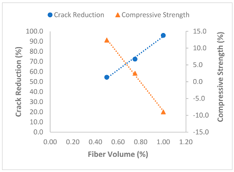 | |
| Compressive Strength y = −42.8x + 34.067 R2 = 0.9981 r = −0.9990 | Crack Reduction y = 83x + 12.003 R2 = 0.9941 r = 0.9970 | ||
| [134] | Volume | 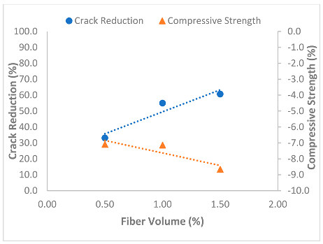 | |
| Compressive Strength y = −1.57x − 6.06 R2 = 0.7739 r = −0.8797 | Crack Reduction y = 27.56x + 22.003 R2 = 0.8972 r = 0.9472 | ||
| [55] | Aspect ratio (@ 0.3% volume fraction) | 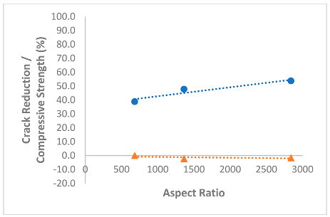 | |
| [55] | Relationship equation | Compressive Strength = −20.21 + 0.061AS + 57.20VF R2 = 0.8319 r = 0.9121 | Crack Reduction = 27.58 + 0.305AS + 34.81VF R2 = 0.9433 r = 0.9712 |
| Ref. | Variable | Regression Lines | |
|---|---|---|---|
| [131] | Volume (H3) |  | |
| Compressive Strength y = −2.73x − 4.89 R2 = 0.75 r = −0.8660 | Crack Reduction y = 29.44x + 29.327 R2 = 0.8538 r = 0.9240 | ||
| [65] | Volume | 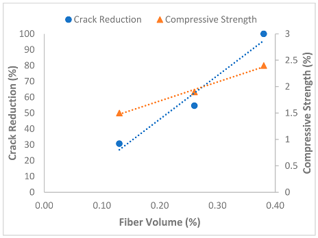 | |
| Compressive Strength y = 3.5928x + 1.0112 R2 = 0.9924 r = 0.9962 | Crack Reduction y = 276.11x − 9.1149 R2 = 0.9607 r = 0.9801 | ||
| [131] | Aspect ratio (@ 0.5% volume) |  | |
| Compressive Strength y = −0.1411x + 4.3337 R2 = 0.211 r = −0.4594 | Crack Reduction y = 0.7376x + 6.5479 R2 = 0.9968 r = 0.9984 | ||
| [131] | Relationship equation | Compressive Strength = −3.781 − 0.013AS + 1.153VF R2 = 0.0465 r = 0.2156 | Crack Reduction = −69.279 + 0.941AS + 39.87VF R2 = 0.8655 r = 0.9303 |
Disclaimer/Publisher’s Note: The statements, opinions and data contained in all publications are solely those of the individual author(s) and contributor(s) and not of MDPI and/or the editor(s). MDPI and/or the editor(s) disclaim responsibility for any injury to people or property resulting from any ideas, methods, instructions or products referred to in the content. |
© 2024 by the authors. Licensee MDPI, Basel, Switzerland. This article is an open access article distributed under the terms and conditions of the Creative Commons Attribution (CC BY) license (https://creativecommons.org/licenses/by/4.0/).
Share and Cite
Folorunsho, A.B.; Kim, S.; Park, C. A Review on the Performance of Fibers on Restrained Plastic Shrinkage Cracks. Buildings 2024, 14, 2477. https://doi.org/10.3390/buildings14082477
Folorunsho AB, Kim S, Park C. A Review on the Performance of Fibers on Restrained Plastic Shrinkage Cracks. Buildings. 2024; 14(8):2477. https://doi.org/10.3390/buildings14082477
Chicago/Turabian StyleFolorunsho, Abidemi Bashiru, Seungwon Kim, and Cheolwoo Park. 2024. "A Review on the Performance of Fibers on Restrained Plastic Shrinkage Cracks" Buildings 14, no. 8: 2477. https://doi.org/10.3390/buildings14082477
APA StyleFolorunsho, A. B., Kim, S., & Park, C. (2024). A Review on the Performance of Fibers on Restrained Plastic Shrinkage Cracks. Buildings, 14(8), 2477. https://doi.org/10.3390/buildings14082477