Article

Tensegrity FlaxSeat: Exploring the Application of Unidirectional Natural Fiber Biocomposite Profiles in a Tensegrity Configuration as a Concept for Architectural Applications

1
Faculty of Architecture and Urban Planning, University of Stuttgart, Keplerstrasse 11, 70174 Stuttgart, Germany
2
BioMat@Stuttgart: Bio-Based Materials and Materials Cycles in Architecture, Institute of Building Structures and Structural Design (ITKE), University of Stuttgart, Keplerstrasse 11, 70174 Stuttgart, Germany
3
BioMat@Copenhagen: Bio-Based Materials and Materials Cycles in the Building Industry Research Centre-TECH-Technical Faculty for IT & Design, Planning Department, Aalborg University, Meyersvænge 15, 2450 Copenhagen, Denmark
4
Department of Architecture (FEDA), Faculty of Engineering, Ain Shams University, Cairo 11517, Egypt
*
Author to whom correspondence should be addressed.
Buildings 2024, 14(8), 2490; https://doi.org/10.3390/buildings14082490
Submission received: 28 June 2024 / Revised: 30 July 2024 / Accepted: 9 August 2024 / Published: 12 August 2024

Abstract

:
Material selection is crucial for advancing sustainability in the building sector. While composites have become popular, biocomposites play a pivotal role in raising awareness of materials deriving from biomass resources. This study presents a new linear biocomposite profile, fabricated using pultrusion technology, a continuous process for producing endless fiber-reinforced composites with consistent cross-sections. The developed profiles are made from flax fibers and a plant-based resin. This paper focuses on the application of these profiles in tensegrity systems, which combine compression and tension elements to achieve equilibrium. In this study, the biocomposite profiles were used as compression elements, leveraging their properties. The methods include geometrical development using physical and digital models to optimize the geometry based on material properties and dimensions. A parametric algorithm including physics simulations was developed for this purpose. Further investigations explore material options for tension members and connections, as well as assembly processes. The results include several prototypes on different scales. Initially, the basic tensegrity principle was built and explored. The lessons learned were applied in a final prototype of 1.5 m on a furniture scale, specifically a chair, integrating a hanging membrane serving as a seat. This structure validates the developed system, proving the feasibility of employing biocomposite profiles in tensegrity configurations. Furthermore, considerations for scaling up the systems to an architectural level are discussed, highlighting the potential to enhance sustainability through the use of renewable and eco-friendly building materials, while promoting tensegrity design applications.

1. Introduction

The ongoing challenge of climate change has become a pressing global concern, particularly within the building industry due to the surge in new constructions. Addressing CO2 emissions during construction and product fabrication has emerged as a great issue that requires consideration both by producers and consumers [1]. Manufacturers are under increasing pressure to reduce the negative environmental impact of their products and often resort to advertising strategies portraying their products as environmentally friendly. However, 53.3% of environmental claims in the European Union have been found to be ambiguous [2]. Considering sustainability, it is crucial to examine all stages of production, from inception to the final product. To confront this challenge, scientists are actively engaged in researching and developing innovative alternatives aiming to reduce carbon emissions. These efforts involve substituting materials and refining production methods. Designers, architects, and engineers involved should meticulously evaluate material compositions when exploring these substitutes, while ensuring that the resulting structures maintain durability and functionality. By adhering to sustainability principles and embracing advancements in research and development, we can collectively strive towards a more environmentally conscious future.

1.1. Biocomposites

Composites are customized materials comprising various combinations tailored to specific applications. Typically, they consist of dispersed particles or fibers embedded within a binding matrix material. Fiber-reinforced polymer (FRP) composites are widely used, most commonly employing glass or carbon fibers as reinforcements due to their strength and cost-effectiveness. Fibers can be categorized as long continuous or short discontinuous, distinguished by the length-to-diameter ratio. In FRP composites, factors such as fiber orientation, thickness, and fiber-volume fraction are critical, especially for structural applications. Experimentation, prototyping, and structural analysis are essential steps in achieving desired outcomes while necessitating careful allocation of time and financial resources. FRP material composition can be customized to achieve lightweight yet strong products with properties like corrosion resistance and high-temperature tolerance, catering to specific needs. Manufacturing processes can also be customized and industrialized to achieve desired results efficiently. Consequently, FRP composites find applications across various industries, including construction, automotive, aerospace, marine, and transportation, among others [3].
In FRP, when at least one of two main components, the fiber or the matrix, are derived from biomass resources, the resulting material is named biocomposite. Biocomposites offer significant potential for sustainability, for example by replacing synthetic fibers such as glass or carbon with natural alternatives such as coir, jute, flax, and hemp, creating the so-called natural fiber-reinforced polymers (NFRP) [4]. Natural fibers present several advantages in terms of sustainability, primarily because they are renewable, biodegradable, and require less energy and fewer chemicals for production, compared to synthetic fibers. They support soil health and biodiversity, and can be recycled more efficiently, contributing to overall sustainability [5]. Natural fibers generally exhibit lower tensile strength, density, and stiffness, compared to carbon or glass fibers, yet they contribute to reduced weight and enhanced fuel efficiency. Additionally, they possess excellent acoustic and thermal properties, albeit with susceptibility to moisture absorption, presenting certain limitations. Each type of natural fiber may exhibit variations in basic chemical compositions, including hemicellulose, cellulose, lignin, and pectin, which directly influence their properties. Therefore, these factors must be carefully considered for each application [6].
Over the past decade, the BioMat Department at the ITKE Institute of the University of Stuttgart has explored the potential of biocomposites in architectural and structural systems. Following the concept of using materials as a design tool, a bottom-up approach has been employed, beginning with the material and its properties. The synergy of material, design, and fabrication has been considered to create various types of biocomposites. This progress has been made possible through the exploration and refinement of various manufacturing techniques, including several molding techniques such as extrusion, pultrusion, tailored fiber placement (TFP), 3D printing, and fused deposition modelling (FDM), among others. Numerous projects have utilized biocomposites created with one or a combination of these techniques [7].

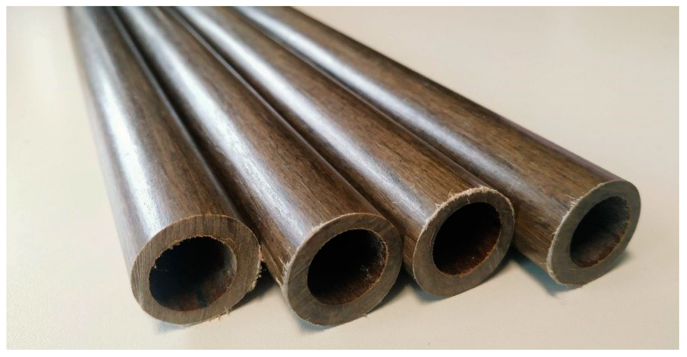
1.2. Pultrusion and Pultruded Profiles
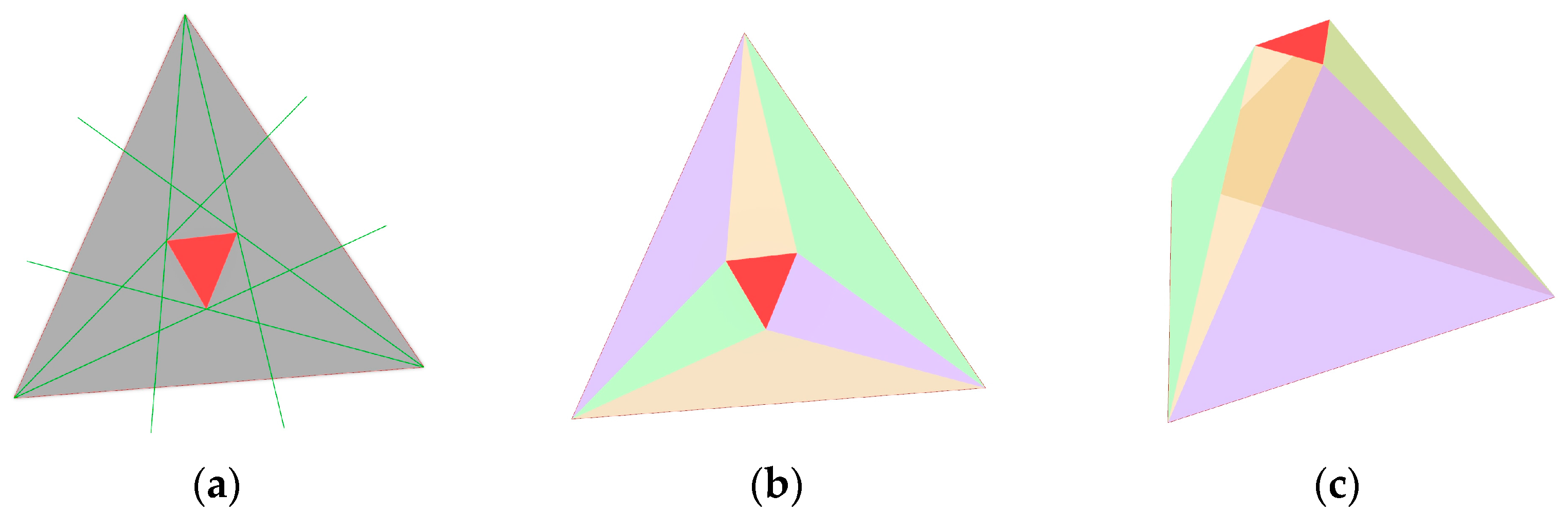
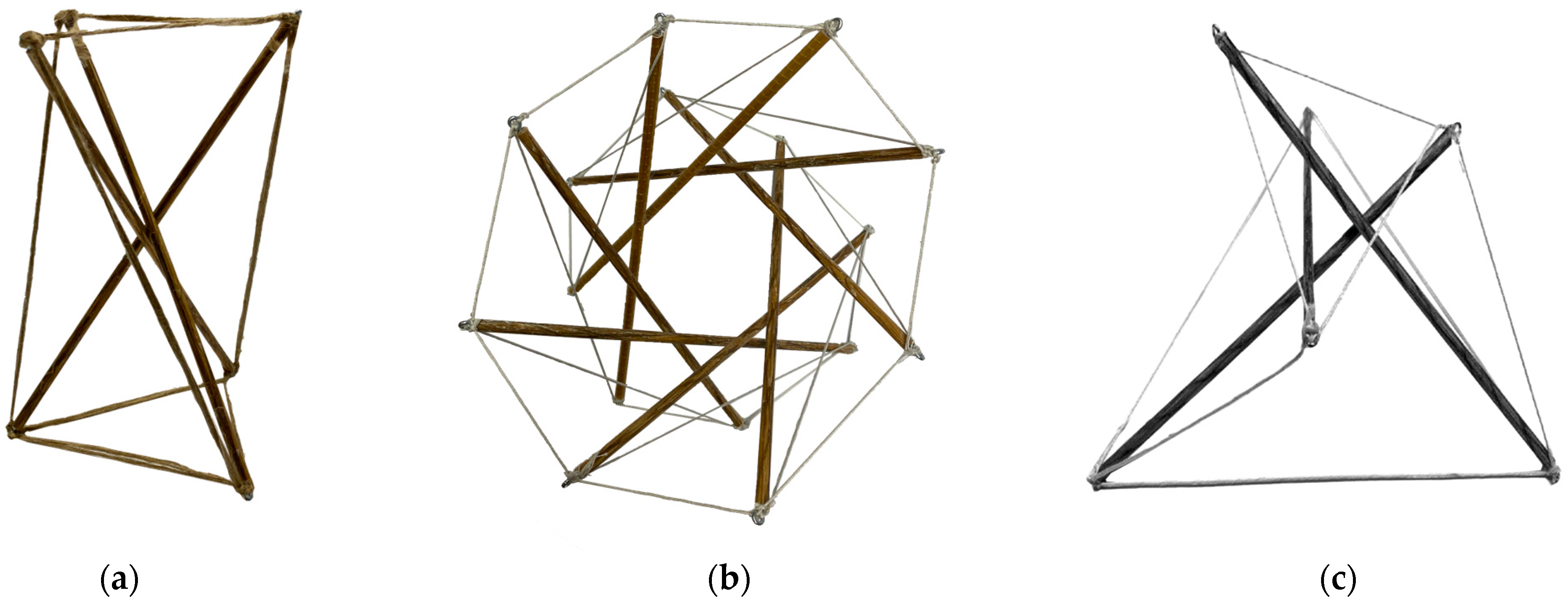
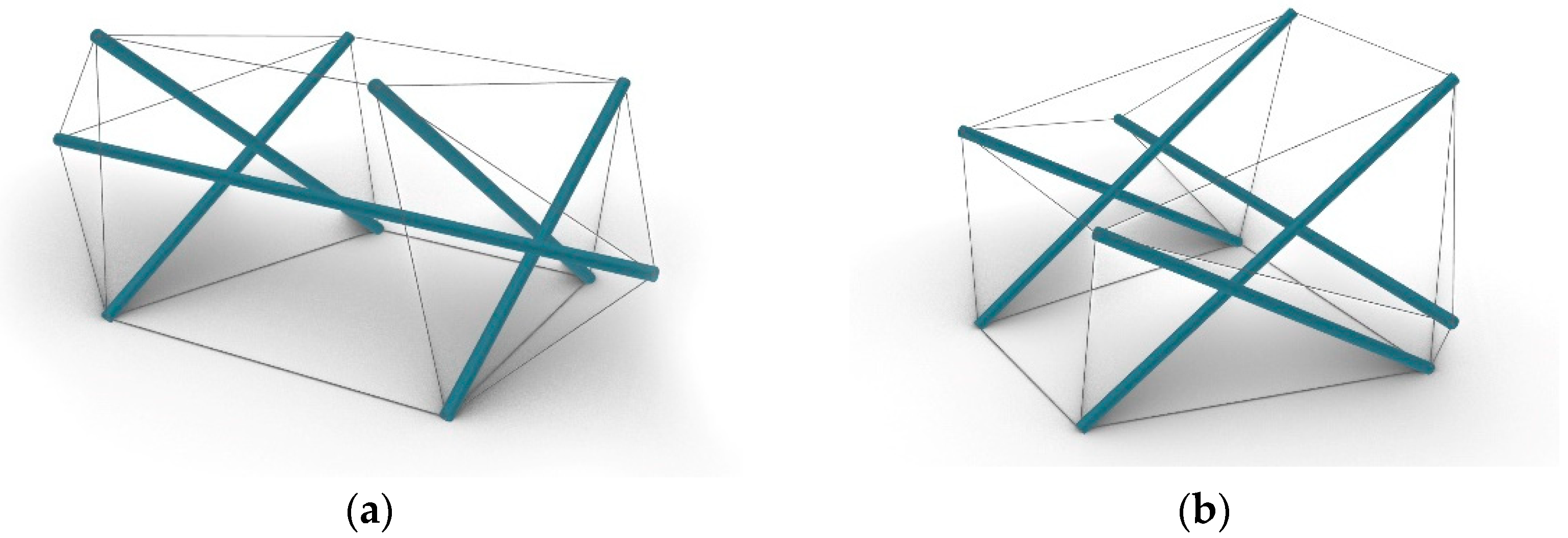
This study will delve into the Pultrusion manufacturing process, as utilized in the framework of the research project LeichtPRO (Pultruded load-bearing lightweight profiles from natural fiber composites), led by the BioMat at the University of Stuttgart. Pultrusion is a continuous process for manufacturing FRP composites with a constant cross-section. The setup comprises several stations which the fibers are guided through. The fiber rovings are sorted by a fiber creel before undergoing moisture extraction in a drying oven. Subsequently, the dried fibers are immersed in the chosen matrix within a resin tank. Guided by orientation plates, the fibers are directed into a heated molding tool, shaping the composite. A caterpillar haul-off system propels the entire production process (Figure 1). The resulting profiles can vary in length, primarily constrained by spatial and transportation limitations.
The so-called LeichtPRO-Profiles produced in this research are made from natural flax fiber rovings reinforced with a custom bio-based matrix system. They are round and hollow, with a diameter of 25 mm and a wall thickness of 4 mm, and can be manufactured to any length. Developed as structural components for various applications, these profiles underwent extensive mechanical testing to determine their properties. They have a compression strength of 118 MPa and an average flexural strength of 300 MPa. They exhibit notable flexibility, with a minimum radius of 2.4 m after a certain length, while shorter sections under 2 m display excellent compression behavior [8,9]. This characteristic inspired their use in this project for tensegrity structures, utilizing short compression bars.
A notable application of these profiles is demonstrated in the LightPRO Shell structure, developed by BioMat in 2021. This structure successfully integrated the biocomposite profiles into an active-bending design, forming a 10-m span lightweight shell combined with a tensioned membrane [10,11]. In a different approach, using shorter members, the profiles were applied in a 5-m span reciprocal canopy showcased at the Venice Biennial 2023, organized by the European Cultural Centre (ECC) [12,13].

1.3. Tensegrity

Tensegrity is a structural system characterized by its ambiguous principles and geometric and mechanical aspects. Coined by Buckminster Fuller in the 1950s, the term combines “tension” and “integrity”. The first tensegrity structure, a sculpture dating back to 1920, was created by the constructivist artist Karl Ioganson [14]. A tensegrity structure achieves equilibrium through a balance of tension and compression forces. Typically, cables provide tensile strength, stabilizing the entire system and maintaining the position of compressive elements, namely bars, ensuring overall structural stability [15,16]. Tensegrity structures exhibit four key characteristics: they can stand freely without external support, their structural members are exclusively linear, they consist of two types of elements—discontinuous struts that bear compression and continuous cables that bear tension—and, notably, the struts do not make direct contact with each other [17].
The basic spatial tensegrity configuration, known as a twist element, utilizes a minimum of three bars and nine cables. By pre-tensioning all cables, the system achieves a stable state where all forces are internally balanced. This inherent stability, due to the anchored nature of the system, allows the twist element to maintain stability regardless of its position in space. Pre-stressing ensures that all structural elements contribute uniformly to load transfer, giving tensegrity structures high stiffness relative to their lightweight nature. Despite their high rigidity, tensegrity structures exhibit controlled deformation capacity. This is particularly advantageous under dynamic or kinematic loads, for example earthquakes, as it protects the system from additional constraints and overloading. However, tensegrity structures are vulnerable to the failure of a single element, which could potentially lead to the collapse of the entire structure. To prevent the risk of sudden collapse, Lars Meeß-Olsohn suggested utilizing the surface load-bearing effect of a membrane to stabilize tensegrity structures [15]. Tensegrity principles are also evident in natural systems. For instance, in the controlled movement of our bodies, bones endure compression while muscles apply stabilizing tension, enabling walking through varying muscle strength [18]. The adaptive nature of tensegrity enables diverse architectural applications. This includes optimizing load distribution, providing solar shading for building envelopes, and altering spatial experiences. These adaptations hinge on controlled adjustments to the length of supporting members [16,19].
An example of a well-known tensegrity structure is the pair of Needle Towers by Kenneth Snelson, which reach heights of 18 m and 30 m. These towers illustrate the concept of arranging basic tensegrity T-prisms vertically. David Geiger drew inspiration from Buckminster Fuller’s Aspension Dome for the roof design of the 1988 Seoul Olympic Fencing and Gymnastics Arena. Unlike traditional radial cables, Geiger employed vertical planes connecting an inner and outer ring [14]. A similar approach involving unwinding multiple ropes to a closed membrane was used in the design of the MOOM pavilion. This structure features a single textile membrane supporting embedded aluminum bars, where the interaction between compression elements and the membrane creates internal mechanical pressure, embodying a tensegrity membrane structure where the membrane replaces conventional cables. Over the past decade, research at the University of Patras has explored tensegrity networks, experimenting with geometries such as ellipsoidal and helicoidal shapes to create functional spaces. These studies have focused on both single- and double-layer tensegrity systems, while also considering the incorporation of flexible skins and mechanisms for interactive applications [20,21,22].

1.4. Scope of the Research

The scope of this research is to investigate the application of the developed biocomposite pultruded profiles within a tensegrity configuration, specifically as the compression elements of the system. Further studies will explore suitable material combinations for the remaining elements to maximize biocomposite integration. To validate these materials, an initial prototype of the basic tensegrity principle will be developed. Subsequently, the project will progress to designing and creating a furniture-scale application, particularly a chair. This project will serve as a proof of concept, showcasing the functional and aesthetic capabilities of biocomposite profiles in tensegrity structures. Subsequently, the research will expand to explore potential architectural applications, evaluating the scalability and practicality of larger structures. Ultimately, this research aims to advance the broader use of biocomposites while promoting tensegrity in sustainable architectural design.

2. Materials and Methods
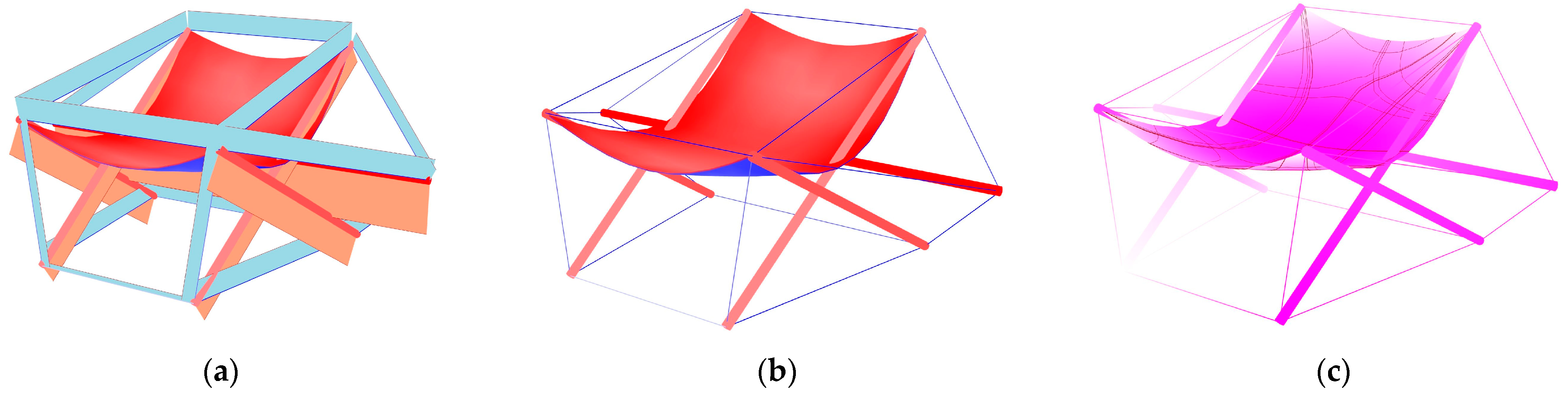
The workflow utilized for the realization of this project is structured into four integral phases: first, the conceptual design stage where initial ideas are developed and refined; second, the geometrical generation and analysis, involving physical and digital models, and the form-finding and structural analysis using a tensegrity solver; third, the selection of the tensegrity system elements, focusing on identifying suitable material options and assessing their properties for the intended application; and fourth, the fabrication and assembly of physical demonstrators, encompassing the physical realization and integration of the designed components. This systematic approach ensures a thorough exploration from concept to implementation in the development of the tensegrity structure (Figure 2).

2.1. Design Concept

Before the concept of a tensegrity structure made of pultruded profiles with a membrane was developed, the initial design focused on the mathematical justification of the geometry and its practical realization. A pattern for constraining the geometry was sought and found through model theory. Model theory, a subfield of mathematical logic, describes the relevant elements of structures using an appropriate formal language. Inspired by the strength of triangles as a structural shape, research was conducted on Morley’s theorem, a significant milestone in model theory [23]. This theorem states that for any triangle, an equilateral triangle can be formed by intersecting its adjacent angle trisectors [24]. When considering solid shapes made of triangles, the versatility and robustness of triangular configurations were explored. For instance, constructing an equilateral Morley’s triangle and examining the resulting geometric properties led to new insights into the stability and strength inherent in such formations (Figure 3). The ability to transform these theoretical principles into practical structures underscores the importance of mathematical logic in geometric design.
In the next stage, the principles of tensegrity systems were considered, and the lessons learned from model theory studies were applied to interpret the concept of Morley’s triangle and its edges as compression or tension elements within the system. During the development and understanding of the tensegrity system’s principles, all edges of the volume were initially considered as compression elements, resulting in a robust framework with intricate joints. To simplify the joints and improve the system while considering the physical behavior of tensegrity, certain elements were eliminated. The remaining elements were translated into tensile components while preserving the original shape. This interpretation of the combination of remaining and dissolved rods as compression and tension elements led to a structural system that meets all requirements of a tensegrity structure. Overall, this study marked the first step in understanding the principles of the intended system and helped establish the basics of concept development.

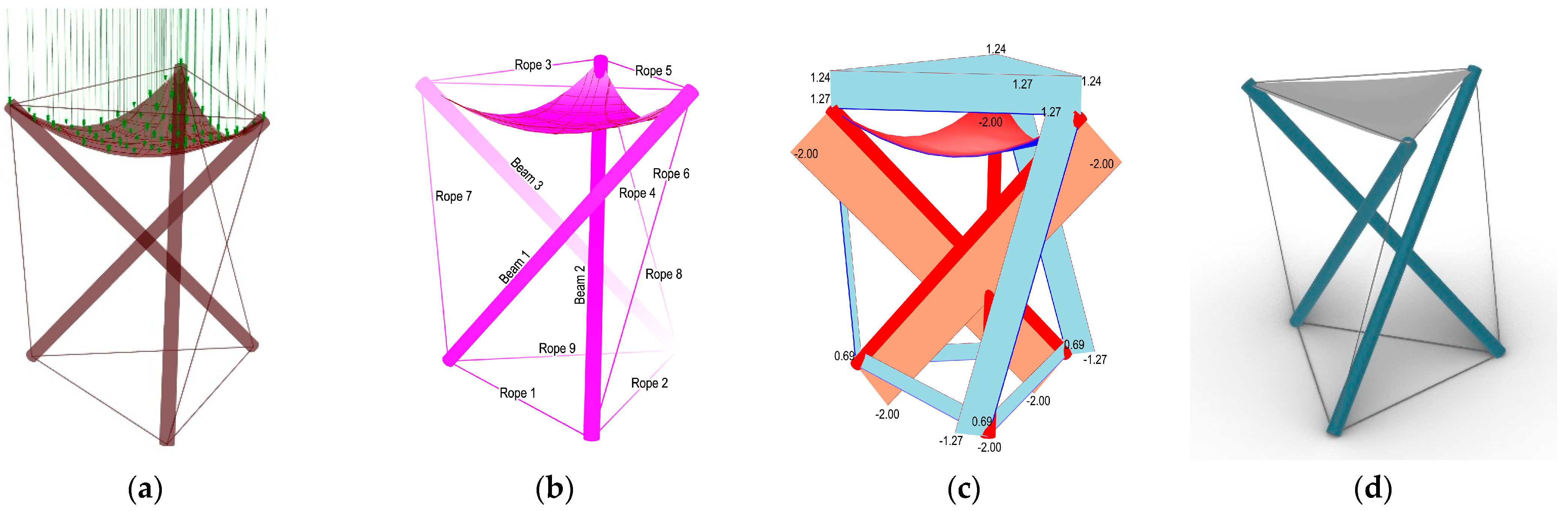
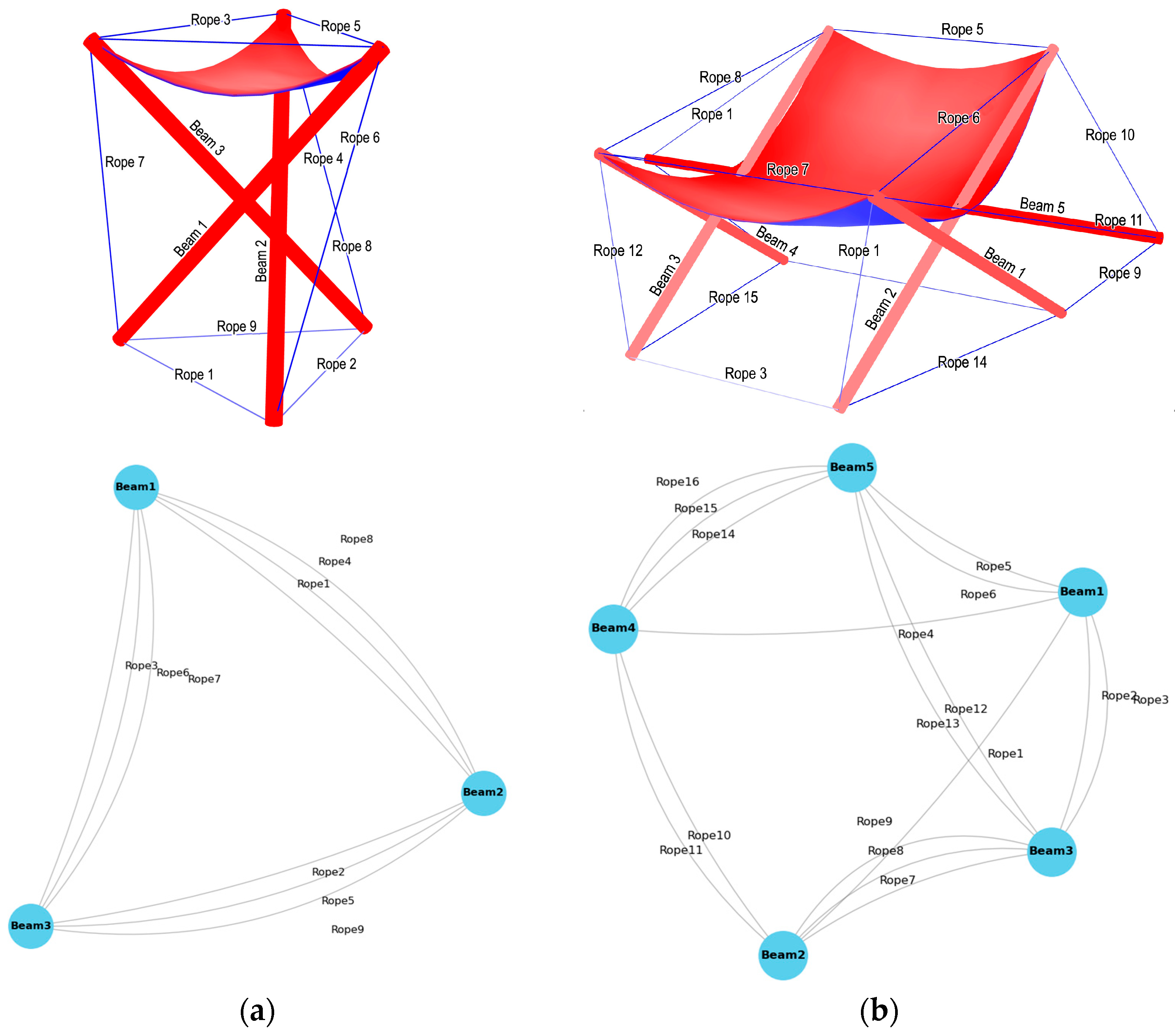
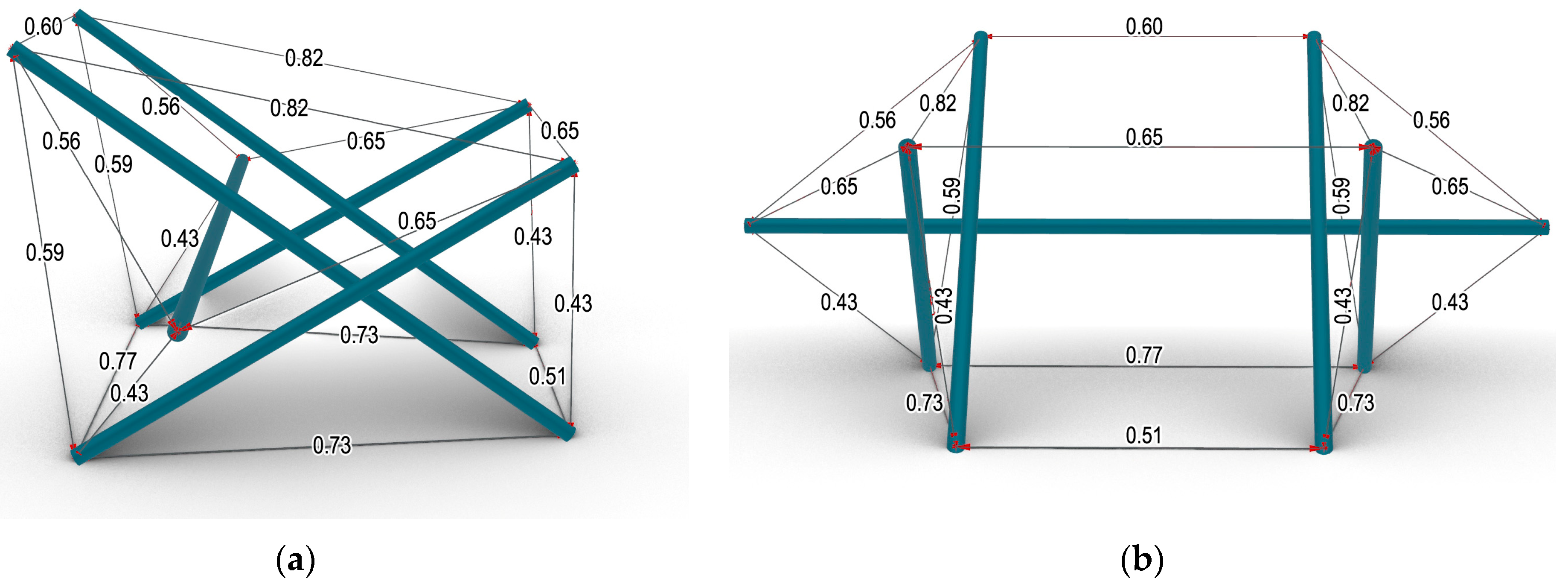
2.2. Geometry Generation and Analysis

At the outset of the geometry-generation process, a hands-on approach utilizing physical modeling was employed. A series of small tensegrity models were constructed to evaluate the diversity and functionality of these systems. In this initial experimental phase, several tensegrity systems were built, following well-known principles and using different numbers of bars. The aim of these first tests was to understand tensegrity systems through hands-on experimentation, focusing on assembly processes and the critical role of tensioning cables in maintaining equilibrium. For these small-scale experiments, 6 mm-diameter, round, pultruded biocomposite profiles were used. These profiles, developed in an earlier stage of the LeichtPRO research project, were made from hemp fibers and a bio-based resin system [8]. The profiles were cut into 20 cm lengths, and small screws with eyelets were inserted at the ends to attach the cables. Various models were developed with different numbers of bars, testing several principles. These included simple twist element tensegrity with 3 bars, more complex configurations with 8 bars, and setups where 3 bars were connected around a horizontal beam acting as the 4th bar in the system, as shown in Figure 4. It was observed that, as the number of bars increased, maintaining tension in the cables became more challenging, making it difficult to keep all bars in place during assembly. Pre-stressing and properly tensioning the overall structures were crucial. An alternative approach involved placing varying numbers of bars within a tensioned membrane, which produced satisfactory outcomes of minimal surfaces. However, this method was not further explored in the geometry-development phase.
Building on an initial understanding of tensegrity systems, potential applications for the developed systems were explored. Given the dimensions of the pultruded profiles (Ø25 mm) and their potential uses, the decision was made to start prototyping on a bigger scale, specifically focusing on furniture. Scenarios related to tables and seating elements were conceptualized. Creating a chair proved to be both challenging and interesting, offering an opportunity for direct validation of the system through use. Traditional tensegrity systems, consisting solely of bars and cables, appeared limited for this application. Drawing inspiration from the literature and previous tensegrity projects that employed membranes as a linking element, the idea to create a hanging seat within the chair design using textiles was generated. These concepts were initially implemented in small-scale models, as shown in Figure 5. Several approaches for integrating the membrane were explored. One approach involved stretching the membrane against some of the bars and replacing local cables. Alternatively, the membrane could be hung from the existing nodes of the tensegrity system. These preliminary models provided valuable insights into the feasibility and functionality of applying tensegrity principles to furniture design.
To access the design development digitally, a parametric model was created within the Rhino/Grasshopper environment using the Kangaroo 2.42 physics simulations plug-in [25]. The aim was to create a balanced tensegrity structure with custom dimensions and additionally simulate the hanging membrane as the seat. The process begins by defining a set of interconnected lines designated to function in either compression or tension. These lines are then processed by the Kangaroo solver, which iteratively moves the points to achieve a state of equilibrium. This results in a stable configuration of the tensegrity structure, which can be adjusted by applying tension forces to modify overall stability. To analyze the structural behavior of the design, the Karamba3D 3.1.4. Finite Element Analysis (FEA) plug-in [26] was integrated into the script. This allows for the optimization of minimum displacement under given loads. The tensegrity structure, comprising pre-defined compression and tension elements, is inputted into the Karamba3d solver as beams. In addition, the seating area is defined as a flat surface resulting from the intersection points of the compression bars, which is inputted as a shell. After configuring the material properties and applying a distributed load to the shell—for example, this can be approximately 80–90 kg when designing a chair—the displacement, overall force applied, and stress lines of the shell can be computed. A simple representation of the parametric development of a tensegrity geometry is presented in Figure 6.
After exploring the main tensegrity principles and establishing a parametric model for generating multiple designs, various configurations were examined. Considerations included material usage, applicability, and ergonomic factors tailored to the chair design, alongside envisioning scalability for future architectural applications. Considerations on the applicability of the biocomposite profiles were included, initially starting with the testing of different geometries using Ø6 mm pultruded profiles. The cross-section of the final profiles, measuring Ø25 mm, was integrated into the digital model to facilitate geometry development, structural simulation, and calculations.
After exploring the basic system (Figure 6), additional designs were generated and developed, increasing the number of elements and complexity. The first iteration involved converting one compression element into a horizontal beam while retaining the other two crossing bars and adding two more in a similar configuration. In this concept, the set of these two elements can be horizontally multiplied along the beam indefinitely. The horizontal beam bridges the sets of two crossings (Figure 7a). This system offers the potential for expansion in length by stacking multiple units or extending the horizontal bar and adding more crossings. However, the extension possibilities of this system are limited by the material strength of the horizontal beam and its intended application.
This system was found significantly promising for furniture applications, adding its expandability for various uses. The design was further developed and optimized featuring a larger and wider design, providing sufficient space for a suspended seating and leaning area. In this configuration, the inclinations of the four bars were adjusted to meet the specific requirements of a chair, resulting in a more ergonomic and functional design (Figure 7b). Using the developed parametric model, the design underwent further optimization to determine the best combination of lengths and inclinations to support the design. Subsequently, the incorporation of a textile to create a hanging seat effectively integrating both tension and compression elements will ensure the chair’s stability and comfort. After rigorous testing and validation in both physical and digital models, this final geometry was selected as the final design concept for the chair prototype. Named Tensegrity FlaxSeat, the chair combines its system type with the main structural element, a biocomposite made from natural flax fibers. The next steps will involve further design refinements, optimization, and material exploration for the remaining system elements.

2.3. Tensegrity System Elements

As previously explained, the regular tensegrity system consists of two primary elements, compression and tension elements, along with their connections at the nodes. In this project, an additional element is integrated as a seat. The selection criteria are based on the properties and intended functions of these materials within the system, detailed later in this section.

2.3.1. Compression Elements

As previously mentioned, this research aimed to apply the newly developed natural fiber biocomposite profiles (Figure 8) in a tensegrity configuration. The biocomposite profiles were chosen as the compression elements due to their linear nature and stiffness in shorter sections, along with their compression strength of up to 31.2 kN, making them suitable for the intended application. Although the profiles exhibit flexibility in longer lengths, they perform well in shorter sections of less than 2 m, making this application appropriate within this range. Given that this material is new, the application remains challenging and requires verification through physical tests. Additionally, considerations for connections with other elements in the system must account for the unique properties of the biocomposite material.

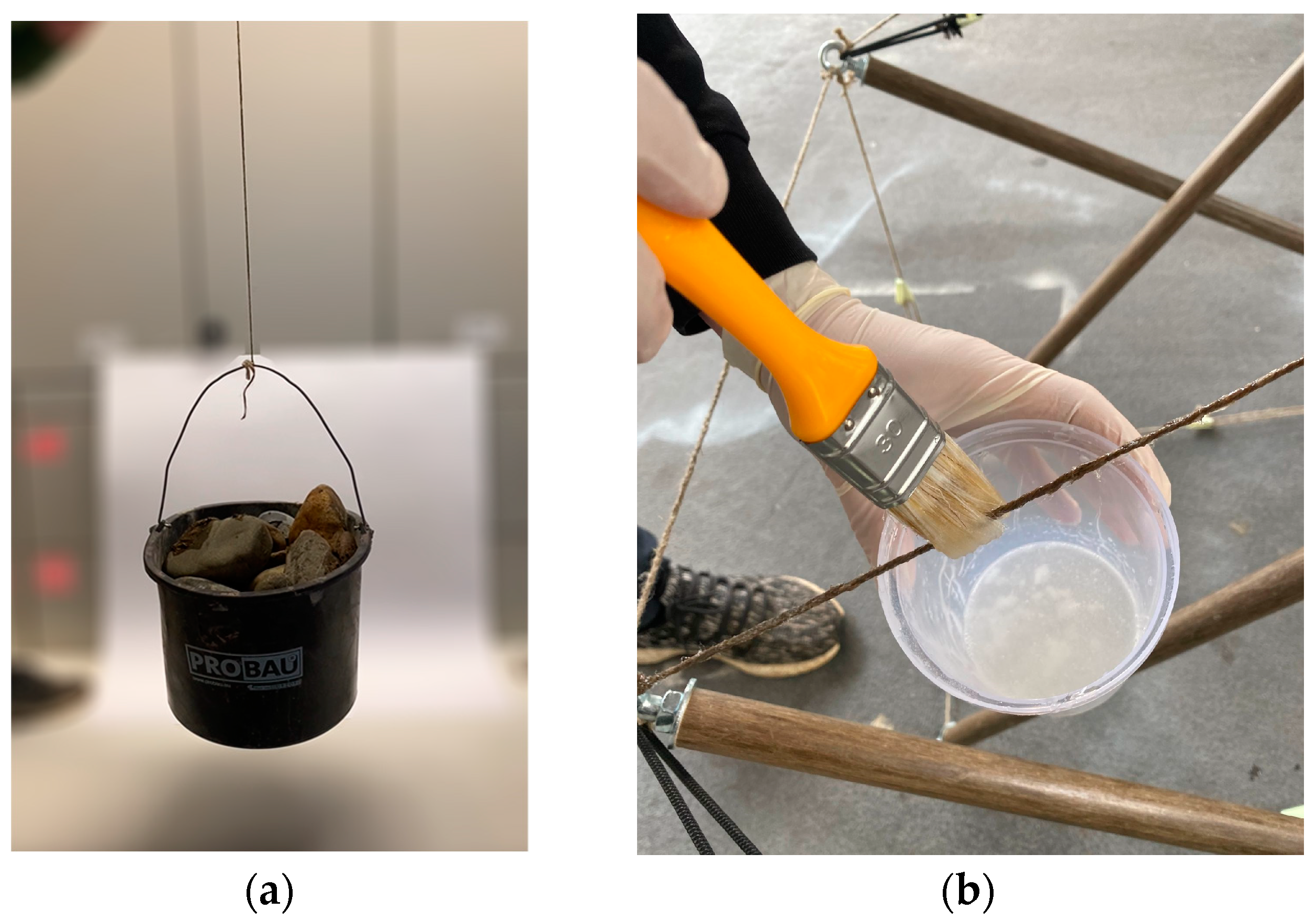
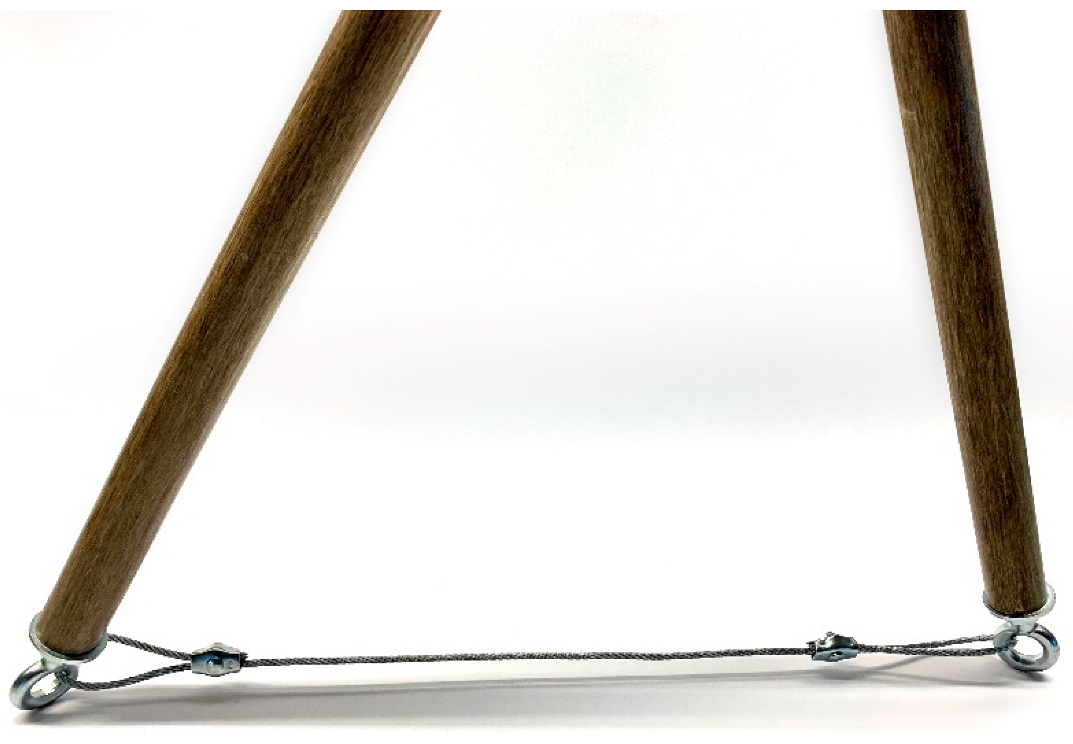
2.3.2. Tension Elements
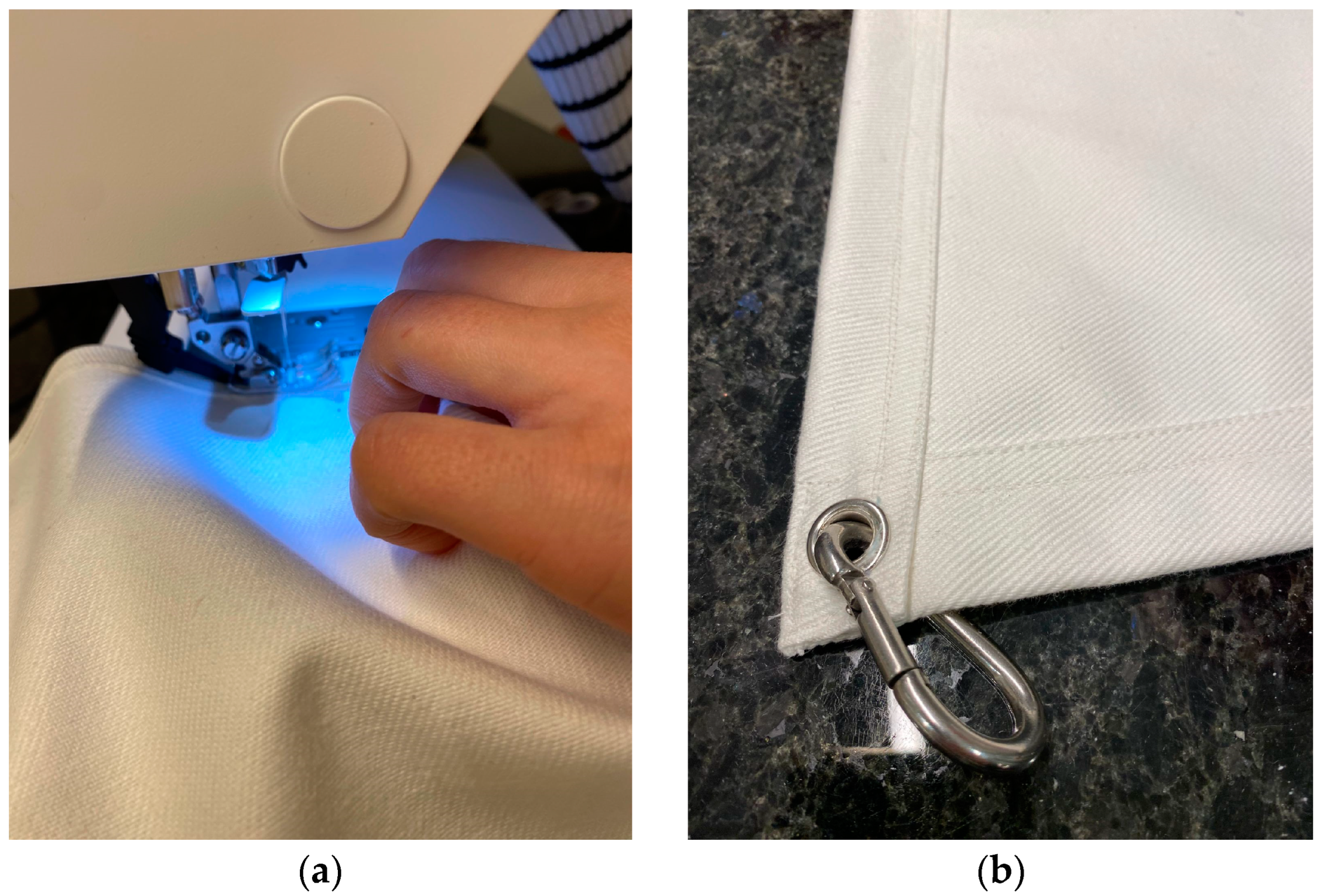
In the search for the ideal material for the tensile elements, various materials were tested to determine their suitability for the structure’s requirements. Initially, flax fiber was tested as a potential candidate due to its natural origin and its use in the pultruded profiles. Raw flax fibers, which were non-twisted with a 1000 tex count, were used. These fibers could easily be pulled apart by hand, requiring additional treatment to make them suitable for the application. Connecting raw natural fibers proved challenging—knots had to be created by hand, wrapping the fibers around the connection element, which was difficult due to their nature. To address these challenges, methods to enhance the fiber’s structure were explored. Twisting or braiding the fibers was initially tried to prevent them from tearing. The flax yarn was braided to enhance its thickness, thereby increasing its stiffness, and in a simple test it could hold more than 50 kg (Figure 9a). In the next trial, the fibers were impregnated with a resin (RIM135 from company Hexion based in Columbus, Ohio) to improve their properties and prevent damage during handling. The flax yarn was impregnated by hand for this test (Figure 9b). While this process increased the strength of the fibers, it introduced multiple drawbacks and constraints, such as controlling resin impregnation, curing on the assembled structure, and maintaining tension in the system. Unlike flexible cables commonly used in tensegrity systems, the cured fibers are stiff and lack the necessary pliability. This rigidity could complicate both the deployment and assembly processes. Additionally, the thin, rigid nature of these elements makes them more fragile, necessitating extra care to prevent damage during handling and operation.
An alternative approach involved using tent cables, also known as guy lines, to serve as the tensile elements in the tensegrity system. These industrial tent cables had adequate load capacity but their elasticity did not meet the system’s requirements. To address this issue, guy line tensioners, named line loks, were used to empirically adjust the tension of the cables during assembly (Figure 10). Initially, this concept appeared effective, however, the cables slipped under high tension, demonstrating that the material was unsuitable for long-term use in a tensegrity structure. This failure indicates that such cables are not viable for furniture-scale applications, and their limitations would be even more pronounced in larger, architectural-scale implementations.
A final solution that met all the requisite criteria was the use of steel cables, specifically 2 mm twisted steel cables with a load capacity of up to 100 kg (Figure 11). To facilitate individual tension adjustment of each cable during assembly, one end of the cable was fixed while the other was made adjustable. This was achieved by securing one end of the cable and employing a tensioner on the adjustable end. The tensioner allowed for easy adjustments to achieve the required tension in the system. The cables were tensioned to the defined lengths based on the design specifications, although additional empirical adjustments might be necessary to ensure optimal performance. Details of the elements to complete the connection of the steel cables are provided in the following section.

2.3.3. Seating Area

To enhance the functionality of the tensegrity system and to create a seating area adaptable to various configurations, an additional component was integrated. To simplify assembly and reduce system complexity, a hung textile element was employed, attached to the nodes to form the seating area. Based on the chosen geometry, the textile was suspended from four nodes, creating a suspended seat. Several materials were considered for the textile. Initially, a sturdy cotton twill fabric, commonly known as denim, was used. Pockets were sewn at the corners for direct attachment to the nodes. However, despite reinforcing the fabric by doubling and tripling the layers, it remained too elastic and the stitches tore under tension. To resolve this issue, the material was switched to textiles specifically used in tents, such as cotton, polyester, or canvas. For this project, a white canvas textile was selected. The edges of the textile were reinforced by doubling the fabric, employing double stitching, inspired by techniques used in parachute construction. Eyelets were added to the corners of the reinforced edges to facilitate the attachment of carabiners, which linked the textile to the node eyelets for easy assembly (Figure 12). This approach ensured the durability and stability of the seating area, making it suitable for long-term use.

2.3.4. Connections

Following the requirements of a tensegrity system, the pre-stressed cables acting as the tensile elements must be anchored at each end of the compression elements, here the pultruded profiles, coming from different directions and angles. To achieve this, a universal joint type was essential for all nodes of the system, where compression and tension elements intersect. To reduce complexity, all connections were standardized throughout the entire structure. As an overview, the components at each node include a connection element at the profile ends for securing the steel cables, along with additional fixtures, such as the seat adjusted at specific nodes. Typically, each node in a tensegrity structure involves at least three cables intersecting, a number that can increase in more intricate configurations. Therefore, it is crucial to be able to connect and individually tension each cable at these joints during assembly.
Various options were explored to find optimal attachments for the pultruded profiles. Considering the profiles’ cross-section geometry—a 25 mm hollow with an inner diameter of 17 mm—an expansion-anchor fitting within the inner diameter was considered suitable for these connections. An expansion-anchor with an eyelet proved to be a viable solution, capable of securing up to 200 kg, and it was M10 size so it perfectly fit inside the hollow profiles. This anchor could be securely installed within the profile, and its eyelet provided an ideal element for connecting cables from any direction.
To secure the tensile elements and facilitate pre-tensioning and adjustments during assembly, duplex clamps were employed to lock the two ends of the steel cables at specified lengths. One end was directly anchored into the eyelet of the dowel inside the profile, while the other end was connected to a turnbuckle tensioner equipped with a hook and eyelet. This assembly allowed for systematic tensioning of the system, simplifying both assembly and subsequent disassembly processes.
Regarding the textile attachment, an eyelet was integrated within the textile material, enabling connection via a carabiner to the node. This type of connection also serves as a universal joint, ensuring simple connectivity from any angle. Figure 13 provides an overview of all components meeting at the node.

2.4. Fabrication and Assembly Process

Once the geometry is finalized, the fabrication and assembly process can commence. After confirming the dimensions of the compression and tension elements through the Kangaroo engine, the design is prepared for production. The dimensions of the elements are exported from the digital model, providing the necessary information for (pre-)fabrication and subsequent assembly. For the compression elements, specifically the pultruded profiles, they need to be cut to the precise lengths required. Each profile end must then be fitted with the chosen dowel with expansion anchor and eyelet. For the tensile elements, the lengths of the steel cables must be calculated by subtracting the length of the turnbuckle and adding the necessary extra length for creating the steel connections. The steel cables can then be pre-fabricated by attaching duplex clamps to create the required lengths and end loops. The final cable length will be fine-tuned during the tensioning of the system. Regarding the seating area, the textile needs to be pre-fabricated by cutting it to the appropriate size, sewing the edges for reinforcement, and punching eyelets at the corners.
At this stage, all elements are prepared for assembly. To identify the interconnectivity of the components, a graph representation was created as part of the parametric model, illustrating how the components connect. This graph can be exported for any geometric configuration. Figure 14 demonstrates the graph for two geometries: the basic three-element tensegrity system and the final design intended for the furniture application. This graph can allow users to proceed with the final assembly at their location. First, all elements need to be interconnected following the provided instructions. Next, the steel cables should be tensioned using the turnbuckle. At this stage, it is essential to measure the length between the endpoints of the compression bars to ensure the cables are optimally stressed. The final structure is completed by mounting the seating area onto the main frame with carabiners.

3. Results

Having completed the design development and material selection, two furniture-scale prototypes were built to validate the system, and the chosen materials and their combinations. Following the assembly system, an initial prototype adhering to the basic tensegrity principle with a twist element consisting of three bars was constructed. In this prototype, guy line cables were utilized and pre-stressed with line loks (Figure 15a). This prototype was developed during the early stages of the material and system development, and served as a preliminary step before finalizing the chair prototype. The second and final prototype is a 1.5-m chair that integrates all the components discussed in Section 2.3, including steel cables and a suspended textile seat (Figure 15b). These two prototypes demonstrate the application of biocomposite pultruded profiles within a tensegrity system, showcasing both aesthetic and functional qualities. The subsequent sections compare material usage for both systems and also present the findings from structural analysis in comparison with physical load testing on the built prototypes.
Table 1 provides an overview of the quantities and material usage for the two prototypes. This detailed preliminary data sets the stage for the subsequent in-depth structural analysis of the system in the two configurations. By examining the material composition and quantities used, we gain valuable insights into the foundational aspects of the prototypes, especially when considering scaling-up the system. This information is crucial for understanding the overall design and potential performance of the system, enabling a thorough evaluation of its effectiveness. Such an evaluation is essential when considering architectural applications, where structural integrity and material efficiency are paramount.

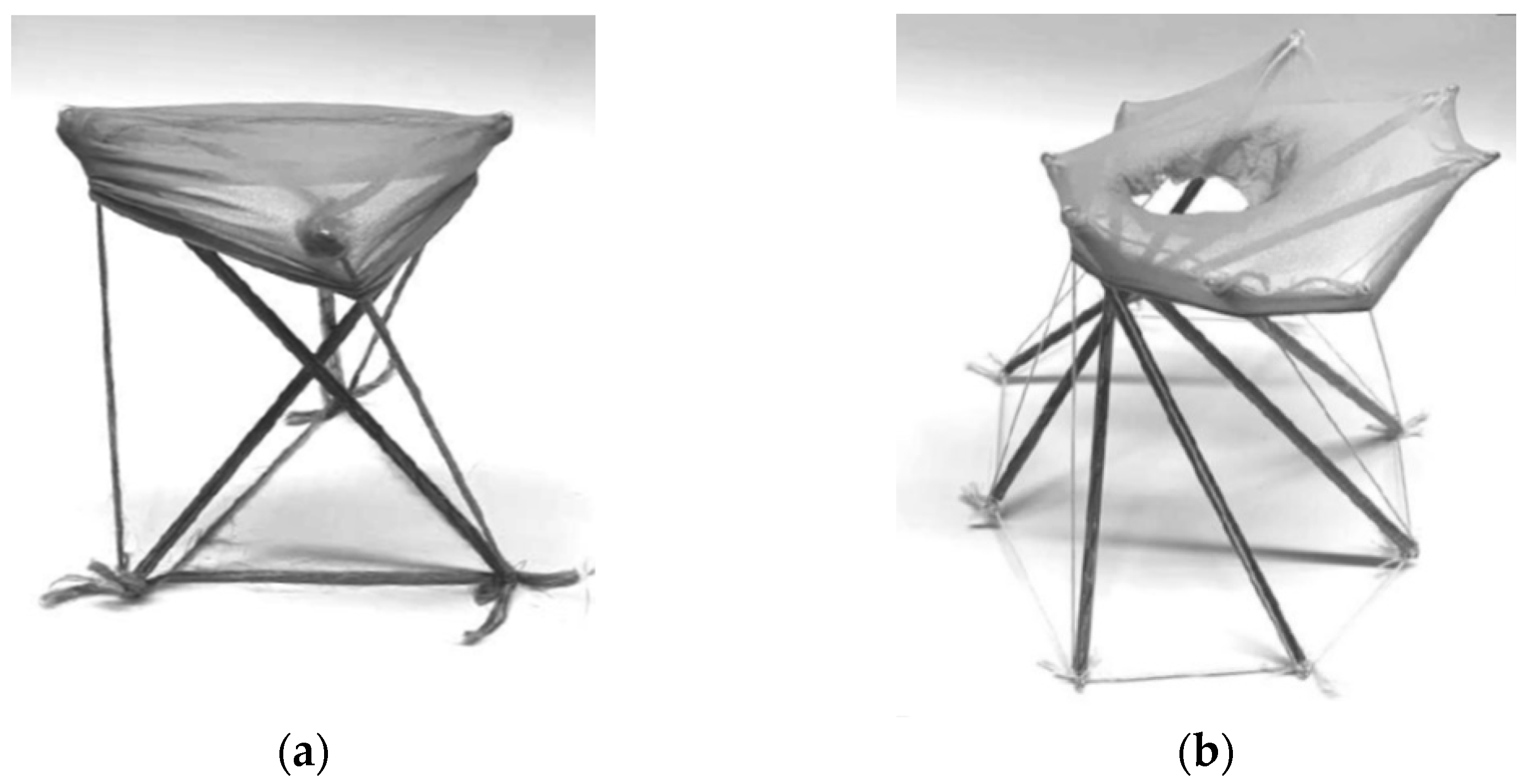
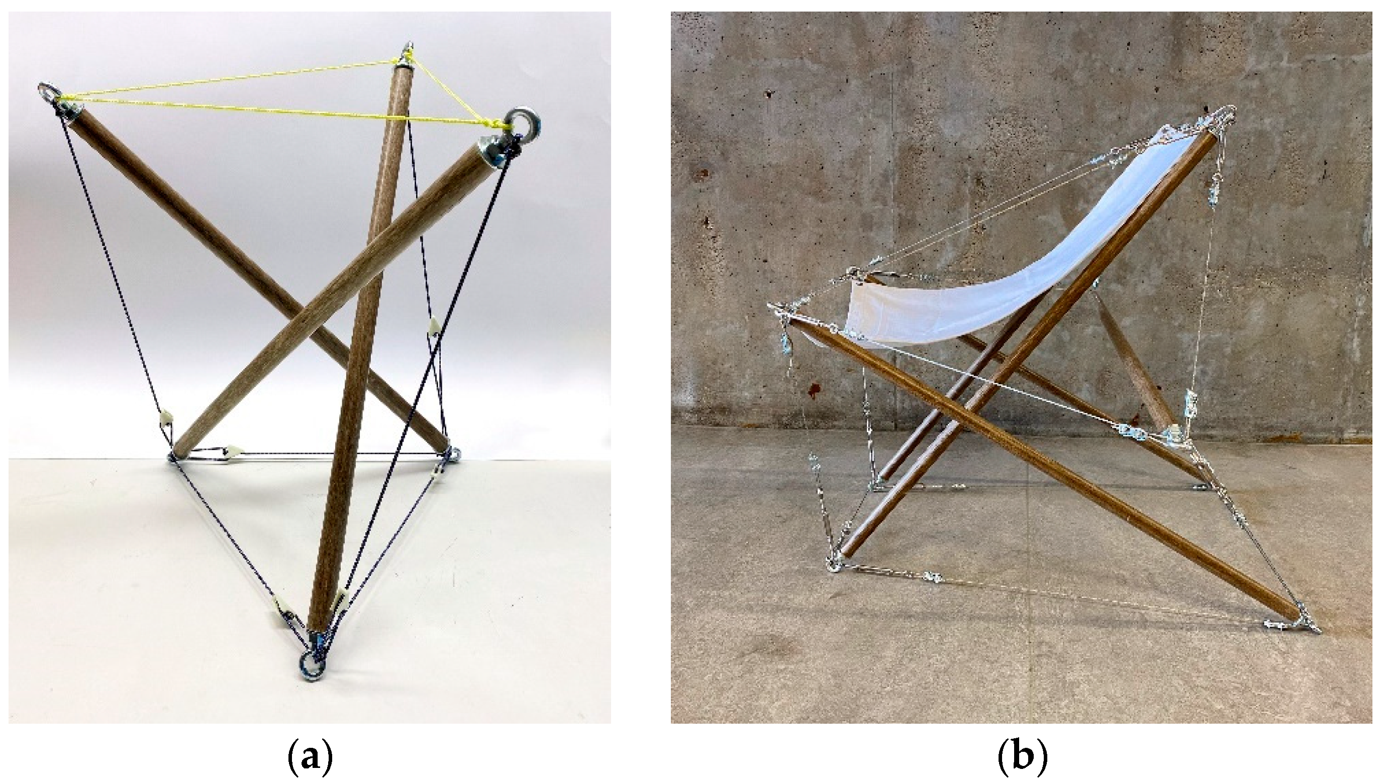
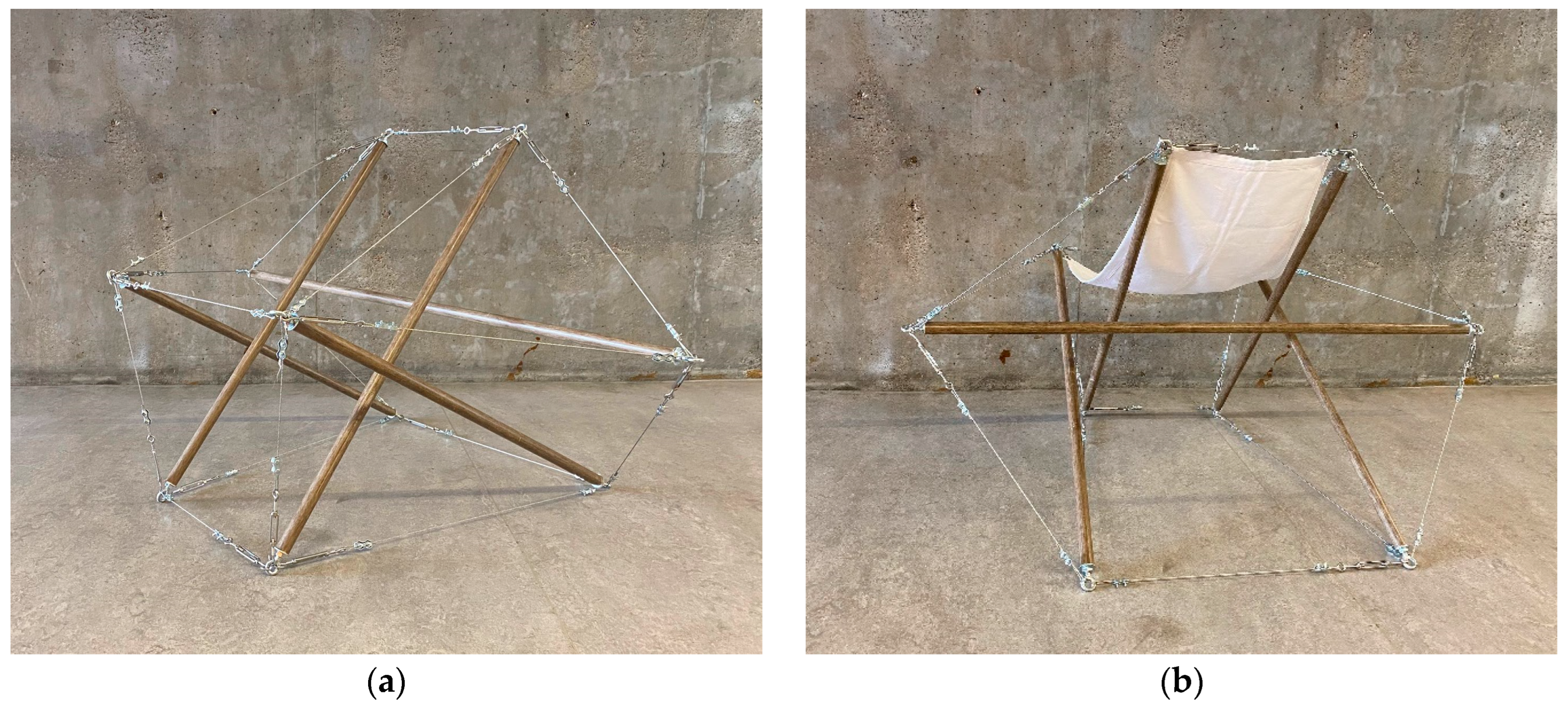
3.1. Prototype of Basic Tensegrity Principle

The first prototype is constructed with a simple, point-symmetric tensegrity structure, analogous to the twist element. Featuring only three compression bars, it demonstrates a high degree of stiffness with nearly-equal load distribution across its cables and beams. To maintain a high degree of stiffness in the presence of an additional 50 kg horizontal load, it is necessary to pre-tension the steel cables by 2 mm/m relative to their maximum utilization factor. Exceeding a certain utilization threshold could result in component failure, potentially leading to the collapse of the entire structure. A preliminary analysis using Karamba3d was conducted to evaluate the specific geometry of the structure. Table 2 presents the analysis output for the three main elements of the system—the anchors, the beams, and the cables—detailing the lengths and loads of each component. The results from both digital simulations and physical testing indicate that this simple tensegrity structure exhibits high stiffness and can support the weight of a person, making it suitable for furniture-scale applications (Figure 16).

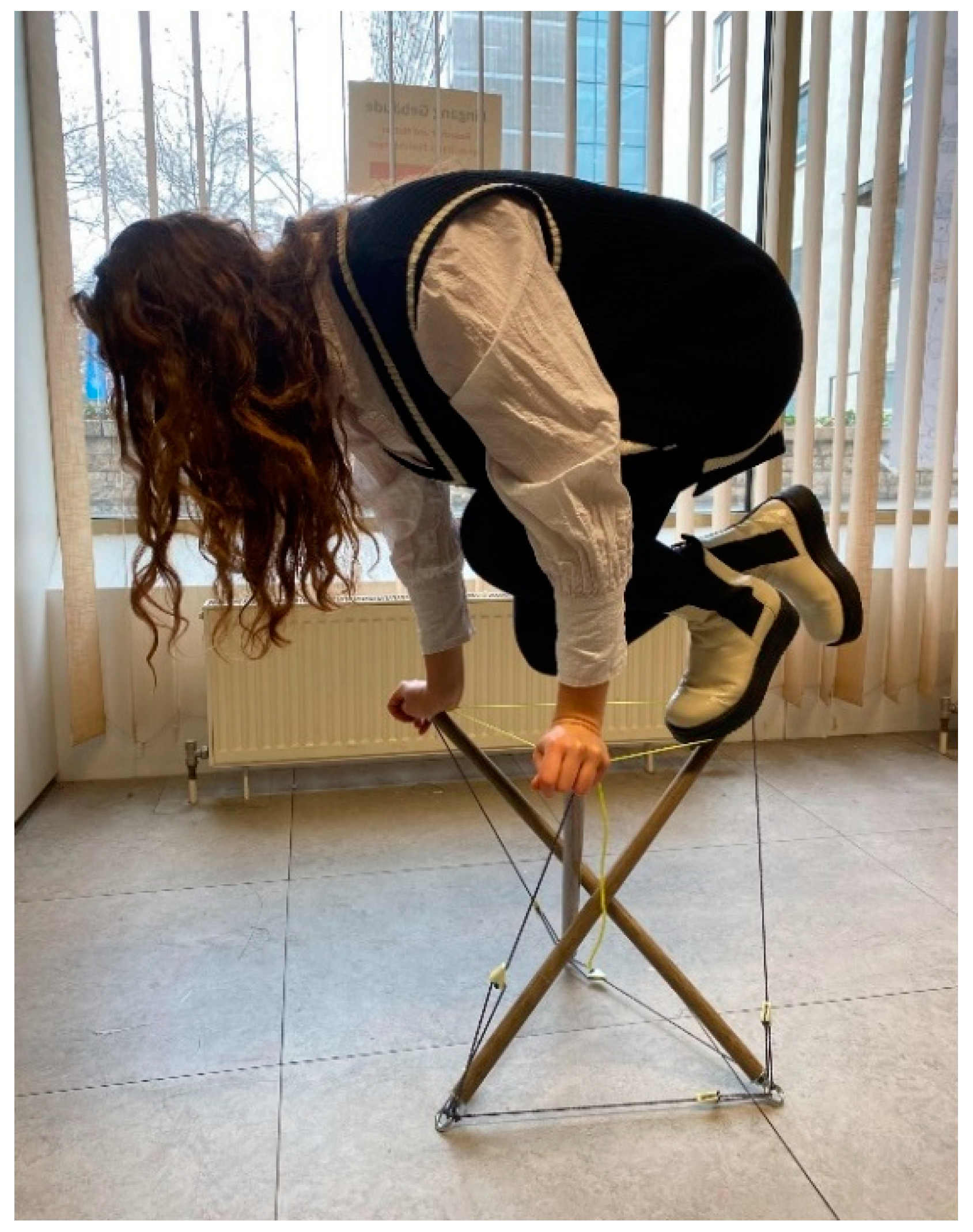
3.2. Final Prototype: Tensegrity FlaxSeat

The second and final prototype is axisymmetric, with the opposing components similarly loaded. To provide a comfortable seating area, the crossings have been designed with different inclinations. This increases the leverage effect, which causes greater forces to be exerted on the relevant elements. During physical testing, the system exhibited a tendency to oscillate. To address this issue, additional cables were attached vertically from the two high points to the other element of the crossings. However, subsequent analysis by Karamba3d (Figure 17) revealed that these additional cables have a negative impact on the system’s ability to bear loads in the presence of vertical loads. This occurs because the action line of the pre-tensioned cables aligns with the direction of the vertical load. Conversely, these cables help prevent movement under other load cases, such as a horizontal 50 kg load. It can be concluded that adding more cables increases the system’s stiffness, but the direction of action and pre-stressing force also contribute to greater displacement. Furthermore, seat test results indicate that, while there may be a negative effect on the load-bearing structure due to oscillation, the perceived comfort of sitting is significantly improved. Table 3 presents the analysis output for the three main elements of this system, similar to Prototype 1.
The maximum displacement under a given load serves as a reliable indicator for comparing and validating the resulting structure. According to the structural analysis using Karamba3d, the final prototype exhibited a maximum displacement of 5.75 cm, slightly less than the initial three-bar prototype. This preliminary calculation highlights the implications and differences observed when transitioning from a basic to a more complex geometry. Further optimization of such structures will be essential in future work to refine and enhance performance based on these findings.
The main components of the system, including the suspended textile seat, are illustrated in Figure 18. Assembly can be easily completed using the diagrams provided in Figure 14. In total, this prototype utilizes five profiles and 17 cables. The profiles measure 1.4 m for the horizontal beam, with two sets of 1 m and 0.8 m each, totaling 5 m of biocomposite profiles. The overall dimensions of the main tension elements are depicted in Figure 19, with the cables totaling 11 m in length. The suspended membrane, covering an area of 0.6 m2, is attached to and supported by the four upper nodes of the system, creating a hammock-style chair. The completed Tensegrity FlaxSeat offers a functional and ergonomic seating solution capable of supporting the weight of one person (Figure 20) and even more.

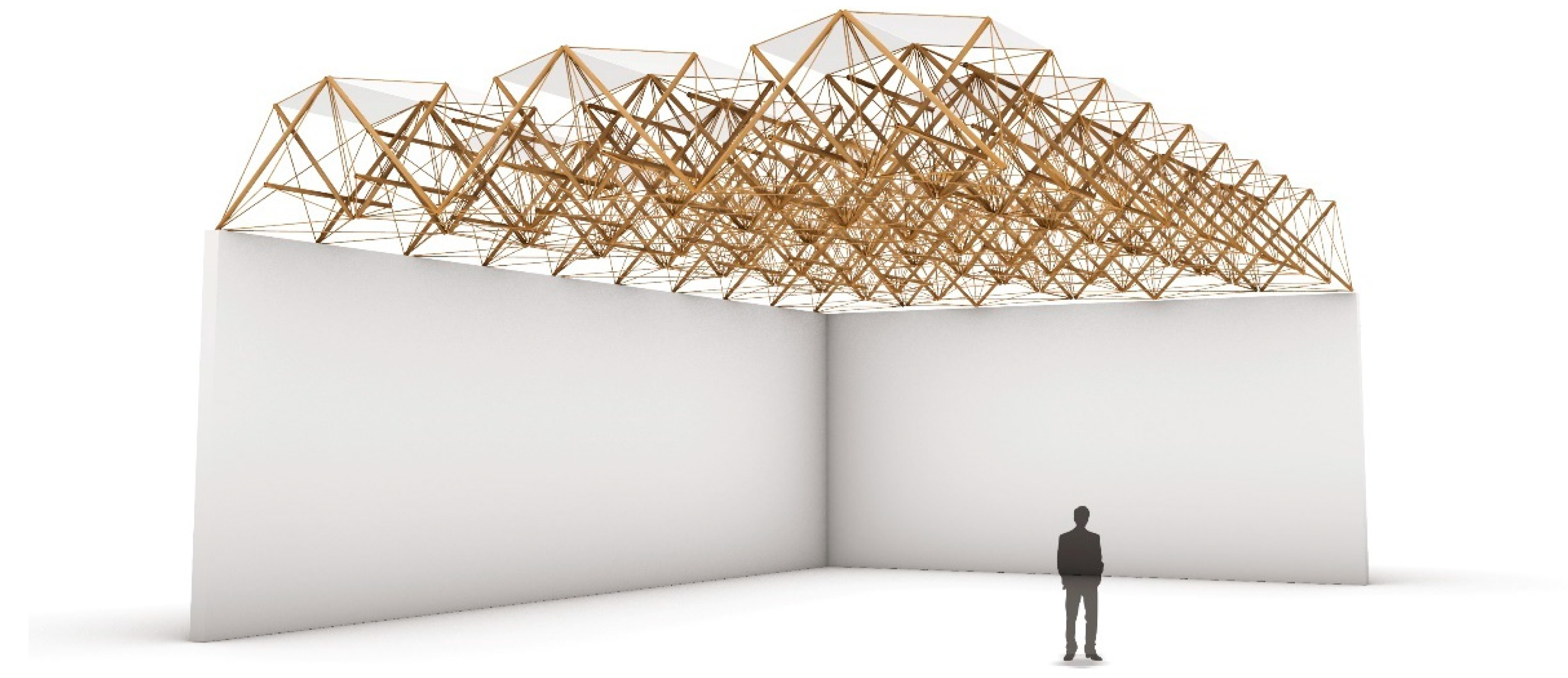
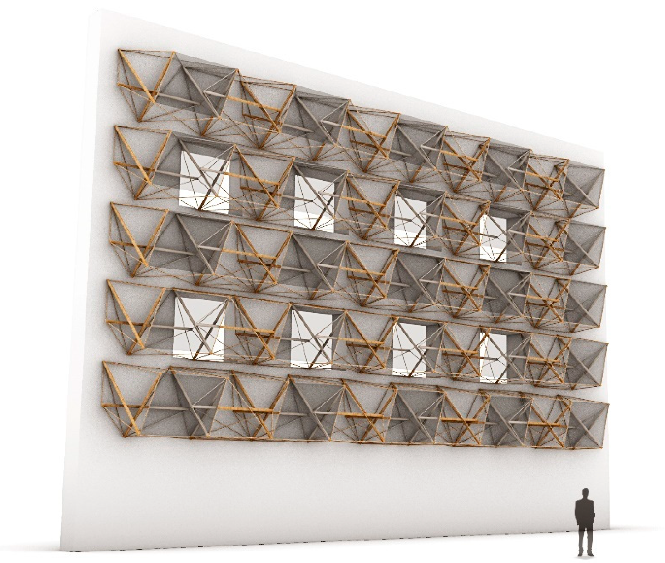
3.3. Architectural Application

The developed system has demonstrated the application of the developed natural fiber pultruded profiles in tensegrity configurations. The furniture-scale demonstrator, already designed and built, serves as an initial validation of the system. This small-scale structural demonstrator was chosen to apply real-world loads and applications. Upon completing this, considerations for scaling-up the system were made. Tensegrity structures are known for their use of short-length bars interconnected by cables, allowing for endless expansion to create structures of various sizes. Depending on the geometry, the resulting system can form different shapes of surfaces, flat or curved. The size and thickness of the selected components, acting as compression elements, can alter the final structure. In scaling-up the application of the developed system, considerations of the applicability of the biocomposite profile as one of the main structural materials are included. The developed geometry can be used as a module that can be replicated and expanded in multiple directions to create larger spatial surfaces. Two different designs have been developed to showcase the suggested applications.
In the first suggested larger-scale structural application, the system is extended along two horizontal axes, creating a larger space-frame-like structure that can function as a canopy covering larger areas (Figure 21). The integration of additional textiles can also be utilized here, producing varying degrees of shade underneath and creating an interesting and functional space. Textiles can be attached in various configurations to provide more or less shade according to required use. However, this concept only offers sun protection—rain protection would require additional systems to enclose the space, which still remains challenging. In a different concept, the modular tensegrity system is developed in a vertical format, serving as a façade or second skin for an existing building (Figure 22). In this case, textile elements can be strategically placed according to the building’s orientation to provide shade. The system can be adapted to different building sizes, as it can extend to any length. Additionally, the initial module can be modified to fit the required dimensions. However, considerations regarding weathering and the suitability of the system’s components and materials for exterior applications have not yet been addressed in this work and should be researched further before implementing such applications.

4. Discussion

In this study, a comprehensive approach combining hands-on experimentation, parametric modeling, and material testing was employed to explore the feasibility and applications of natural-fiber biocomposite profiles in tensegrity structures. Although the study focused on a small-scale application of the developed system, it provided valuable insights and implications for future applications. Initial experiments involved constructing small-scale tensegrity models using the biocomposite profiles, highlighting tensioning cables’ critical role in maintaining equilibrium. The challenge of maintaining tension increased with the complexity of designs, emphasizing the importance of precise assembly processes and tension management. Prototyping focused on furniture applications like chairs and tables, showcasing the adaptability of tensegrity systems in real-world contexts. Integrating a hanging seat within the chair design demonstrated how additional elements can enhance functionality and validate system feasibility. Parametric modeling in Rhino/Grasshopper using Kangaroo2 for physics simulations enabled digital optimization of the tensegrity system. Integration of Karamba3d facilitated preliminary structural analysis to ensure system performance under varying loads.
Material selection played a pivotal role, with biocomposite profiles made from natural fibers and bio-resin chosen for compression elements due to their stiffness and sustainable properties. After testing various materials, steel cables were selected for tensile elements, highlighting the challenges in maintaining tension and stability with alternative fibers and materials. The final prototype, Tensegrity FlaxSeat, integrated biocomposite profiles, steel cables, and a suspended textile seat, validating both aesthetic appeal and functional performance. Physical testing revealed oscillation issues under certain loads, prompting adjustments in cable arrangement to balance stability and comfort. The prototype’s structural integrity and ergonomic design were confirmed through physical and digital validation.
Future research directions include optimizing tensegrity structures through advanced digital simulations and exploring alternative materials to enhance structural properties and sustainability. Scaling-up tensegrity systems for larger applications, such as roof and canopy structures or facades, presents opportunities for innovative design solutions. Addressing challenges like weathering and material durability, and integrating functional elements like shading textiles, will be crucial for broader implementation.

5. Conclusions

In conclusion, this study underscores the potential of tensegrity systems in architectural design, supported by advances in digital modeling and sustainable materials. Future research can further advance applications across various scales and disciplines, paving the way for sustainable and functional design solutions. While tensegrity is a well-established principle, and the developed prototypes adhere to recognized tensegrity configurations, through this work the authors aim to promote the integration of tensegrity systems into architectural contexts, encouraging their application in sustainable design practices.
This research not only demonstrates the possibilities of using natural fiber pultruded profiles but also highlights the potential of biocomposites in creating lightweight structures and advancing the construction industry as a whole. The primary aim is to encourage sustainability by promoting the use of eco-friendly alternatives in the building sector. Ongoing advancements in biocomposite manufacturing technologies promise to contribute to sustainable development objectives and influence the future of constructed environments. Future studies will focus on optimizing the material composition to enhance their properties and on exploring the potential for developing fully biocomposite structures using components sourced from biomass-based materials. This will also involve the creation of biocomposite connectors for integration into tensegrity and other structural systems. This study, along with multiple other applications of the newly developed natural fiber pultruded profiles, demonstrates the applicability of this new material across a range of scenarios. Overall, this research showcases their potential to revolutionize building practices by offering lightweight, durable, and eco-friendly solutions.

Author Contributions

Conceptualization, M.R. and E.S.; methodology, M.R. and E.S.; software, M.R.; validation, M.R.; investigation, M.R.; resources, E.S.; data curation, M.R.; writing—original draft preparation, M.R. and E.S.; writing—review and editing, E.S. and H.D.; visualization, M.R.; supervision, E.S. and H.D.; project administration, E.S.; funding acquisition, H.D. All authors have read and agreed to the published version of the manuscript.

Funding

This research was partially funded by the Fachagentur Nachwachsende Rohstoffe e. V. (FNR, Agency for Renewable Resources) under Bundesministeriums für Ernährung und Landwirtschaft (BMEL, Federal Ministry of Food and Agriculture) throughout the research project Leicht-Pro: Pultruded load-bearing lightweight profiles from natural fiber composites (FKZ: 22027018), managed by Hanaa Dahy, director of the BioMat Department at ITKE, University of Stuttgart.

Data Availability Statement

The original contributions of this study are detailed within the article; further inquiries can be directed to the authors.

Acknowledgments

The project was developed in the seminar Material Matter Lab (Material and Structure, Winter Semester 2021/2022), offered by BioMat (The Department of Biobased Materials and Materials Cycles in Architecture) at ITKE at the University of Stuttgart by students Markus Renner, Theresa Hillemanns, and Marcel Spielvogel, under the supervision of Hanaa Dahy and the tutoring of Evgenia Spyridonos. The pultruded profiles were developed as part of the LeichtPRO research project, for which the Deutsche Institute für Textil- und Faserforschung (DITF) and Bio-Composites And More GmbH (B.A.M.) developed the materials and processes, and CG TEC Carbon und Glasfasertechnik GmbH handled the pultrusion-manufacturing process. BioMat was the project administrator and was responsible for the design, material testing, and realization of research demonstrators.

Conflicts of Interest

The authors declare no conflicts of interest. The funders had no role in the design of the study, in the collection, analyses, or interpretation of data, in the writing of the manuscript, or in the decision to publish the results.

References

  1. Meng, B.; Liu, Y.; Gao, Y.; Li, M.; Wang, Z.; Xue, J.; Andrew, R.; Feng, K.; Qi, Y.; Sun, Y.; et al. Developing Countries’ Responsibilities for CO2 Emissions in Value Chains Are Larger and Growing Faster than Those of Developed Countries. One Earth 2023, 6, 167–181. [Google Scholar] [CrossRef]
  2. Bottega, L.; Brécard, D.; Delacote, P. Greening or Greenwashing? How Consumers’ Beliefs Influence Firms’ Advertising Strategies on Environmental Quality. 2023. Available online: https://ssrn.com/abstract=4522796 (accessed on 6 June 2024).
  3. Shubham; Ray, B.C. Fiber Reinforced Polymer (FRP) Composites in Ballistic Protection: Microstructural and Micromechanical Perspectives; Engineering Materials; Springer Nature: Singapore, 2024; ISBN 978-981-9997-45-9. [Google Scholar]
  4. Dahy, H. Natural Fibre-Reinforced Polymer Composites (NFRP) Fabricated from Lignocellulosic Fibres for Future Sustainable Architectural Applications, Case Studies: Segmented-Shell Construction, Acoustic Panels, and Furniture. Sensors 2019, 19, 738. [Google Scholar] [CrossRef] [PubMed]
  5. Dunne, R.; Desai, D.; Sadiku, R.; Jayaramudu, J. A Review of Natural Fibres, Their Sustainability and Automotive Applications. J. Reinf. Plast. Compos. 2016, 35, 1041–1050. [Google Scholar] [CrossRef]
  6. Madueke, C.I.; Mbah, O.M.; Umunakwe, R. A Review on the Limitations of Natural Fibres and Natural Fibre Composites with Emphasis on Tensile Strength Using Coir as a Case Study. Polym. Bull. 2023, 80, 3489–3506. [Google Scholar] [CrossRef] [PubMed]
  7. Dahy, H. Materials as Design Tool: Digital Fabrication Strategies for Sustainable Architecture. Technol.|Archit. + Des. 2023, 7, 153–158. [Google Scholar] [CrossRef]
  8. Spyridonos, E.; Witt, M.-U.; Dippon, K.; Milwich, M.; Gresser, G.T.; Dahy, H. Natural Fibre Pultruded Profiles: Illustration of Optimisation Processes to Develop High-Performance Biocomposites for Architectural and Structural Applications. Compos. Part C Open Access 2024, 14, 100492. [Google Scholar] [CrossRef]
  9. Spyridonos, E.; Gerstner, A.; Nehmeier, M.; Dahy, H. LeichtPRO-Profiles: Development and Validation of Novel Linear Biocomposite Structural Components Fabricated from Pultruded Natural Flax Fibres with Plant-Based Resin for Sustainable Architectural Applications. Mater. Res. Express 2024, 11, 075308. [Google Scholar] [CrossRef]
  10. BioMat Pavilion 2021: LightPRO Shell|Institute of Building Structures and Structural Design|University of Stuttgart. Available online: https://www.itke.uni-stuttgart.de/research/built-projects/biomat-pavilion-2021 (accessed on 6 June 2024).
  11. Fachagentur Nachwachsende Rohstoffe e. V. Pultruded Load-Bearing Lightweight Profiles Made of Natural Fibre Composites (LeichtPRO). Available online: https://biowerkstoffe.fnr.de/projekte/projektuebersicht/projekte-details?fkz=22027018 (accessed on 6 June 2024).
  12. BioMat at TIME SPACE EXISTENCE, Venice, 2023|Institute of Building Structures and Structural Design|University of Stuttgart. Available online: https://www.itke.uni-stuttgart.de/research/built-projects/biomat_time_space_existence (accessed on 6 June 2024).
  13. Spyridonos, E.; Reiner, A.; Dahy, H. Reciprocal Lightweight Structures with Natural Fiber Biocomposite Profiles through Computational Design and Case Studies Validation. In Proceedings of the IASS 2024 Symposium, Zurich, Switzerland, 26–30 August 2024. [Google Scholar]
  14. Gomez-Jauregui, V.; Carrillo-Rodriguez, A.; Manchado, C.; Lastra-Gonzalez, P. Tensegrity Applications to Architecture, Engineering and Robotics: A Review. Appl. Sci. 2023, 13, 8669. [Google Scholar] [CrossRef]
  15. Jacobsen, N. Tensegrity-Membran-Strukturen. Eine Studie über Entwicklung und konstruktive Umsetzung des Tensegrity-Prinzips im Bauwesen. Ph.D. Thesis, HafenCity Universität Hamburg, Hamburg, Germany, 2018. [Google Scholar]
  16. Rack, S. Formadaptive Tensegrity-Strukturen: Ein Beitrag zur Numerischen Simulation; KIT Scientific Publishing: Karlsruhe, Germany, 2019. [Google Scholar]
  17. Zhang, J.Y.; Ohsaki, M. Tensegrity Structures: Form, Stability, and Symmetry; Mathematics for Industry; Springer: Tokyo, Japan, 2015; Volume 6, ISBN 978-4-431-54812-6. [Google Scholar]
  18. Gan, B.S. Computational Modeling of Tensegrity Structures: Art, Nature, Mechanical and Biological Systems; Springer International Publishing: Cham, Switzerland, 2020; ISBN 978-3-030-17835-2. [Google Scholar]
  19. Charalambides, J.; Liapi, K. Square-Base Double-Layer Tensegrity Structures: Geometric Relations for Modular Tensegrity Assemblies. J. Archit. Eng. 2017, 23, 04017011. [Google Scholar] [CrossRef]
  20. Liapi, K.A.; Georgopoulos, T.; Ioannidi, A.; Kotsalis, A.; Nousias, C.; Spyridonos, E. Interactive Tensegrity Pavilion. Proc. IASS Annu. Symp. 2015, 2015, 1–12. [Google Scholar]
  21. Liapi, K.; Papantoniou, A.; Ioannidi, A. Double-Layer Tensegrity Networks of Helicoidal Shape: From Algorithmic to Physical Models. Proc. IASS Annu. Symp. 2018, 2018, 1–6. [Google Scholar]
  22. Liapi, K.A.; Papantoniou, A. Minimal Surface Tensegrity Structures: Design Algorithm Implementation in Real World Applications. In Italian Workshop on Shell and Spatial Structures; Gabriele, S., Manuello Bertetto, A., Marmo, F., Micheletti, A., Eds.; Springer Nature: Cham, Switzerland, 2024; pp. 626–635. [Google Scholar]
  23. Sarbadhikari, H.; Srivastava, S.M. A Course on Basic Model Theory; Springer: Singapore, 2017; ISBN 978-981-10-5097-8. [Google Scholar]
  24. Ida, T.; Kasem, A.; Ghourabi, F.; Takahashi, H. Morley’s Theorem Revisited: Origami Construction and Automated Proof. J. Symb. Comput. 2011, 46, 571–583. [Google Scholar] [CrossRef]
  25. Piker, D. Kangaroo: Form Finding with Computational Physics. Archit. Des. 2013, 83, 136–137. [Google Scholar] [CrossRef]
  26. Preisinger, C. Linking Structure and Parametric Geometry. Archit. Des. 2013, 83, 110–113. [Google Scholar] [CrossRef]
Figure 1. Pultrusion production line at CG TEC GmbH: (a) flax fiber rovings, (b) fiber-drying oven, (c) resin basin, (d) fibers entering the heated molding tool, (e) pultruded profile Ø25 mm exiting the mold. © Photos: CG TEC, collage: BioMat.
Buildings 14 02490 g001
Figure 2. Workflow diagram.
Buildings 14 02490 g002
Figure 3. Morley’s theorem: (a) Top view of trisectors represented with auxiliary lines building an equilateral triangle, (b) top view of correlated areas, (c) perspective of extruded pyramid.
Buildings 14 02490 g003
Figure 4. Physical tensegrity models: (a) twist element with three bars, (b) symmetric tensegrity configuration with 8 beams, (c) tensegrity system with 3 bars connected around a horizontal beam.
Buildings 14 02490 g004
Figure 5. Tensegrity models integrating membrane to test seating area possibilities: (a) twist element with three bars, (b) symmetric tensegrity configuration with 8 beams.
Buildings 14 02490 g005
Figure 6. Basic tensegrity system simulation: (a) Kangaroo vertical load simulation, (b) displacement, (c) main forces on beams, (d) final analyzed geometry.
Buildings 14 02490 g006
Figure 7. Geometry development configurations: (a) five bars with a horizontal beam, (b) five-bar configuration with modified inclinations for a chair application.
Buildings 14 02490 g007
Figure 8. LeichtPRO profiles, Ø25 mm.
Buildings 14 02490 g008
Figure 9. Tensile element first trial: (a) braided flax fibers holding 50 kg load, (b) impregnating flax fibers with resin.
Buildings 14 02490 g009
Figure 10. Tensile element second trial: guy lines pre-stressed with line loks.
Buildings 14 02490 g010
Figure 11. Tensile element: twisted steel cable.
Buildings 14 02490 g011
Figure 12. Textile fabrication: (a) sewing using double stitches, (b) detail including the eyelet and carabiner for connection.
Buildings 14 02490 g012
Figure 13. Connection point with its components: (a) turnbuckle, (b) biocomposite pultruded profile, (c) dowel with expansion anchor and an eyelet, (d) carabiner, (e) eyelet, (f) duplex clamp, (g) twisted steel cable, (h) textile as seat.
Buildings 14 02490 g013
Figure 14. Graph representation of component connectivity: (a) Prototype 1: basic tensegrity principle, (b) Prototype 2: Tensegrity FlaxSeat.
Buildings 14 02490 g014
Figure 15. (a) Prototype 1: basic tensegrity principle, (b) Prototype 2: Tensegrity FlaxSeat.
Buildings 14 02490 g015
Figure 16. Physical testing of Prototype 1.
Buildings 14 02490 g016
Figure 17. Structural analysis of the second prototype using Karamba3d. (a) Normal forces, (b) utilization, (c) displacement.
Buildings 14 02490 g017
Figure 18. Tensegrity FlaxSeat: (a) main tensegrity components, (b) integration of suspended textile.
Buildings 14 02490 g018
Figure 19. Tensegrity FlaxSeat dimensions: (a) side view, (b) front view.
Buildings 14 02490 g019
Figure 20. Tensegrity FlaxSeat.
Buildings 14 02490 g020
Figure 21. Architectural application for the developed system as a tensegrity canopy.
Buildings 14 02490 g021
Figure 22. Architectural application as a tensegrity facade system.
Buildings 14 02490 g022
Table 1. Material usage of the two prototypes.
Prototype 1Prototype 2
Number of profiles35
Number of cables917
Total length of profiles [m]2.105.00
Total length of cables [m]4.1011.00
Textile seat area [m2]0.080.60
Table 2. Forces and lengths of components of the first prototype.
ElementReaction Force [kN]Length
[m]
Maximum Axial
Normal Stress [kN/cm2]
Anchor 10.27
Anchor 20.27
Anchor 30.27
Cable 1 0.4221.82
Cable 2 0.4221.83
Cable 3 0.4221.82
Cable 4 0.4239.3
Cable 5 0.4239.34
Cable 6 0.4239.35
Cable 7 0.5440.54
Cable 8 0.5440.53
Cable 9 0.5440.57
Beam 1 0.7−0.41
Beam 2 0.7−0.41
Beam 3 0.7−0.41
Table 3. Forces and lengths of components of the second prototype.
ElementReaction Force [kN]Length [m]Maximum Axial
Normal Stress [kN/cm2]
Anchor 10.18
Anchor 20.18
Anchor 30.24
Anchor 40.24
Cable 1 0.4343.06
Cable 2 0.5629.71
Cable 3 0.6539.63
Cable 4 0.518.61
Cable 5 0.7726.65
Cable 6 0.640.96
Cable 7 0.8241.67
Cable 8 0.6540.21
Cable 9 0.8241.68
Cable 10 0.4341.68
Cable 11 0.5629.71
Cable 12 0.6539.63
Cable 13 0.4323.33
Cable 14 0.4323.31
Cable 15 0.7340.36
Cable 16 0.7340.4
Beam 1 1.34−0.44
Beam 2 1−0.32
Beam 3 1−0.32
Beam 4 0.83−0.43
Beam 5 0.83−0.43
Disclaimer/Publisher’s Note: The statements, opinions and data contained in all publications are solely those of the individual author(s) and contributor(s) and not of MDPI and/or the editor(s). MDPI and/or the editor(s) disclaim responsibility for any injury to people or property resulting from any ideas, methods, instructions or products referred to in the content.

