
Research on the Mechanism of Loose Deformation in Weak Fracture Zone Tunnel Surrounding Rock and Support Control


Abstract
:1. Introduction
2. Background and In Situ Stress
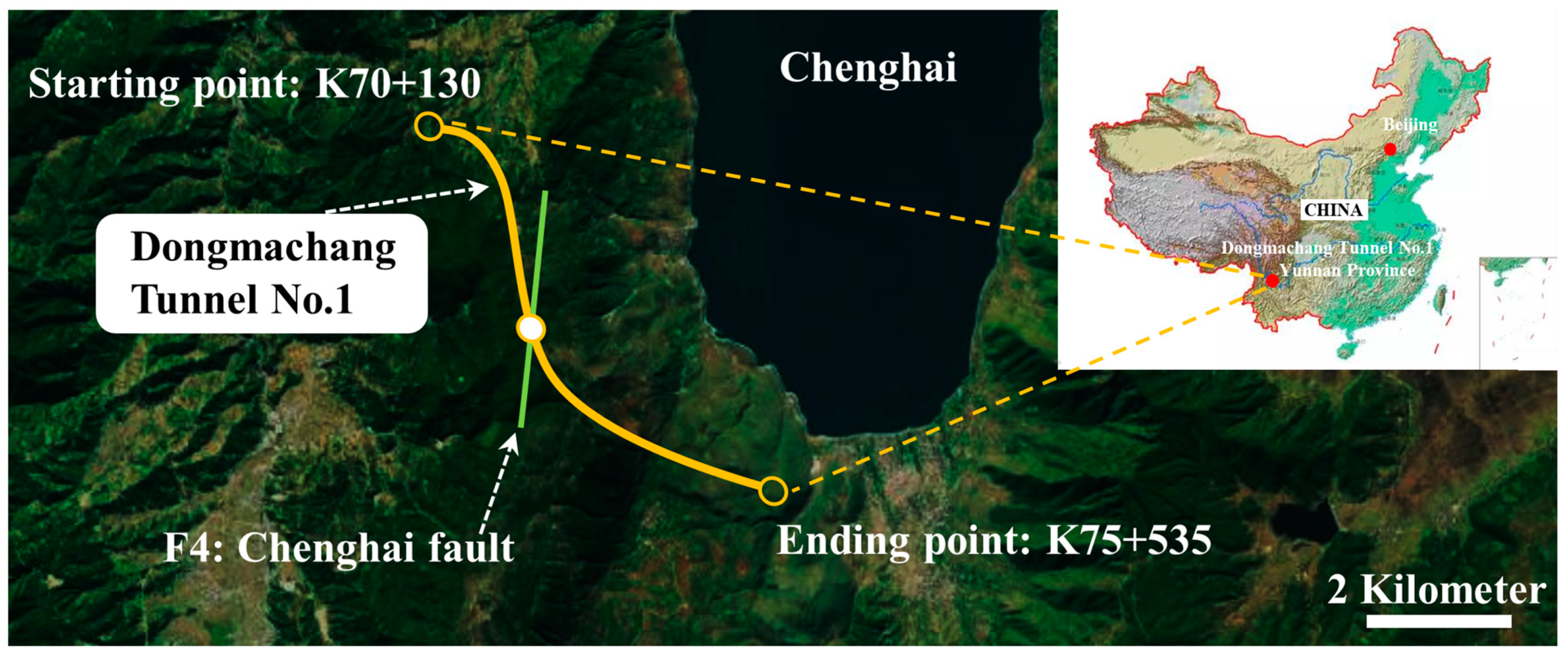
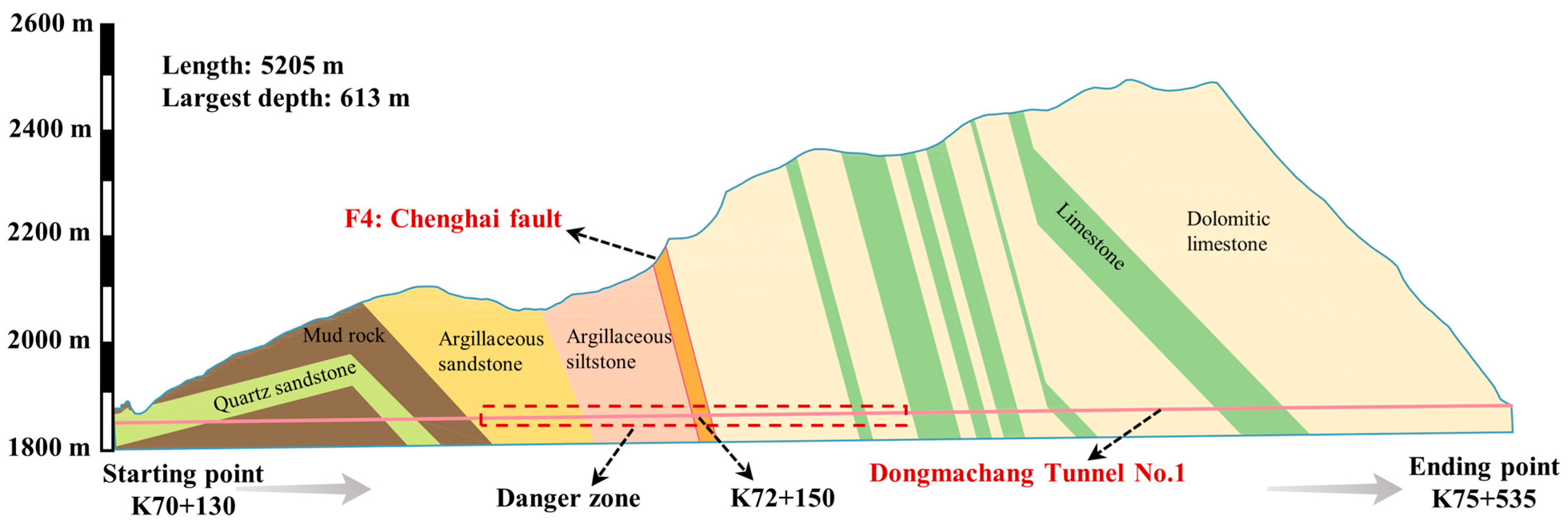
2.1. Engineering Background
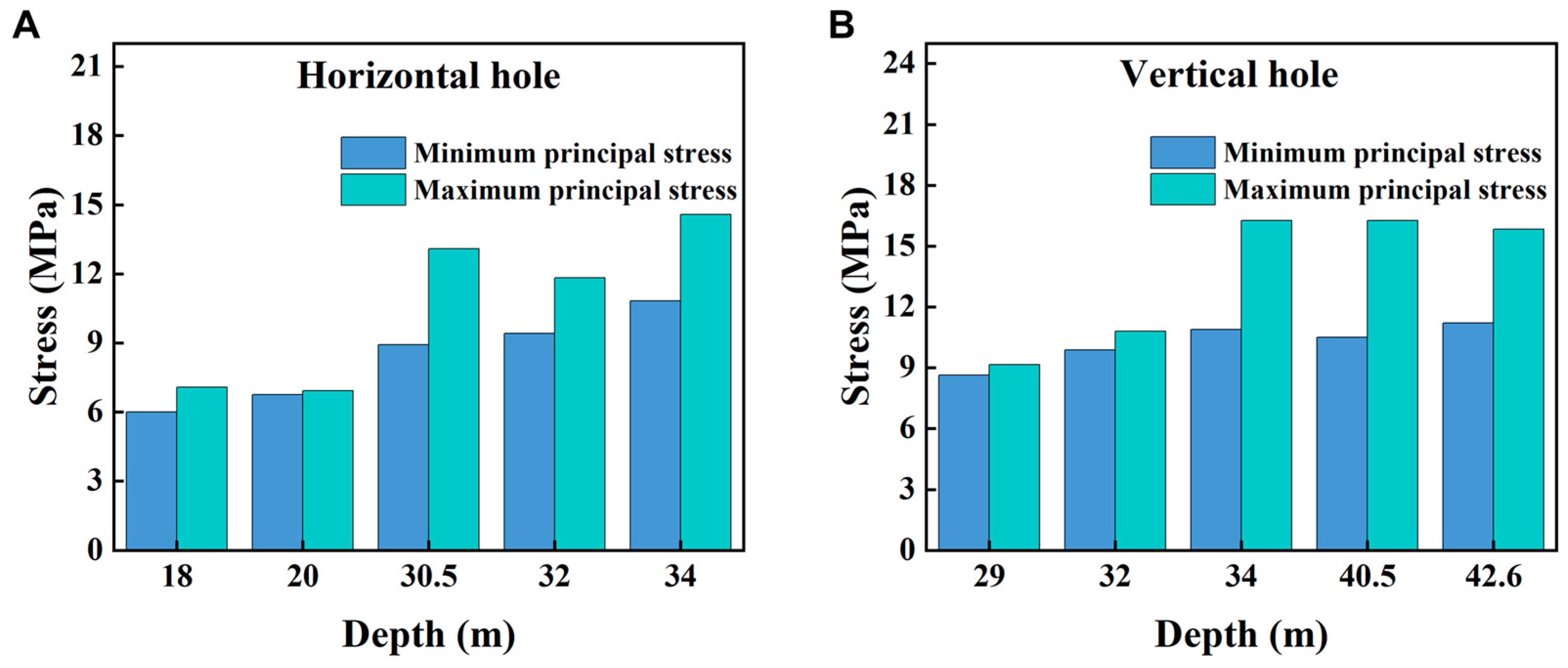
2.2. In Situ Stress
3. Damage Law of Tunnel Lining and Support System
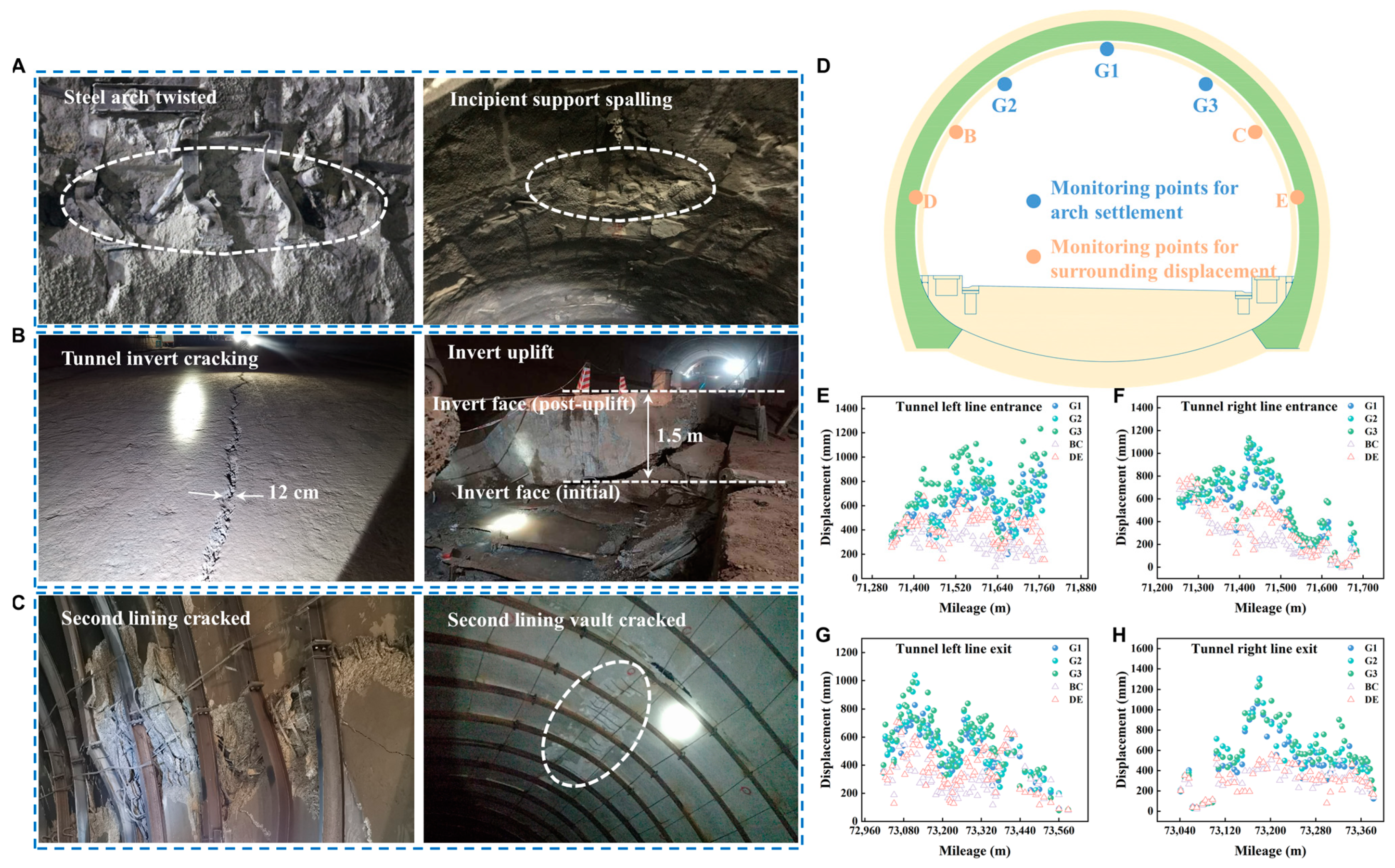
3.1. Tunnel Damage Patterns and Regulations
3.2. Internal Force Analysis of Typical Section
4. Tunnel Deformation Treatment
4.1. Implementation Effect of Support Scheme
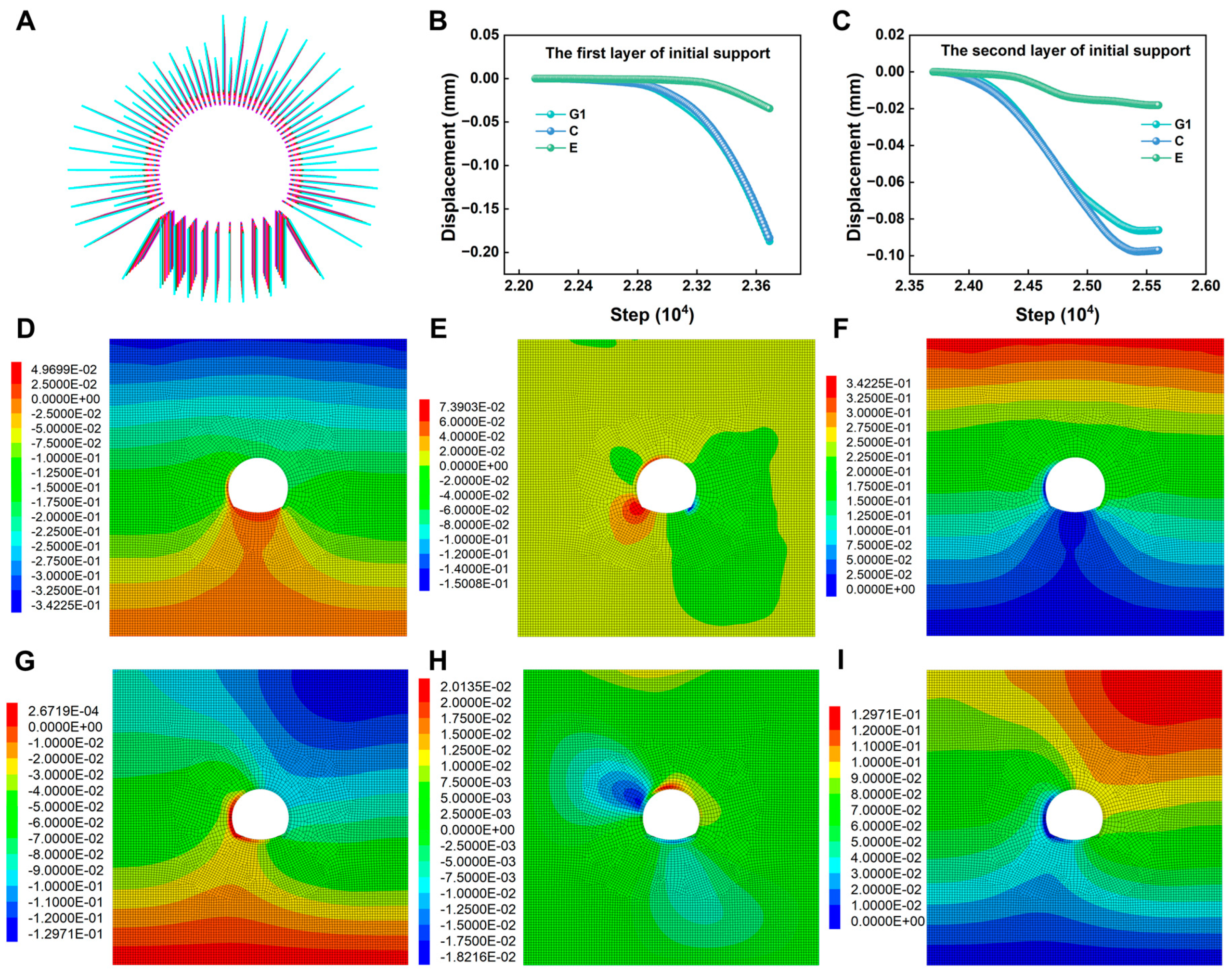
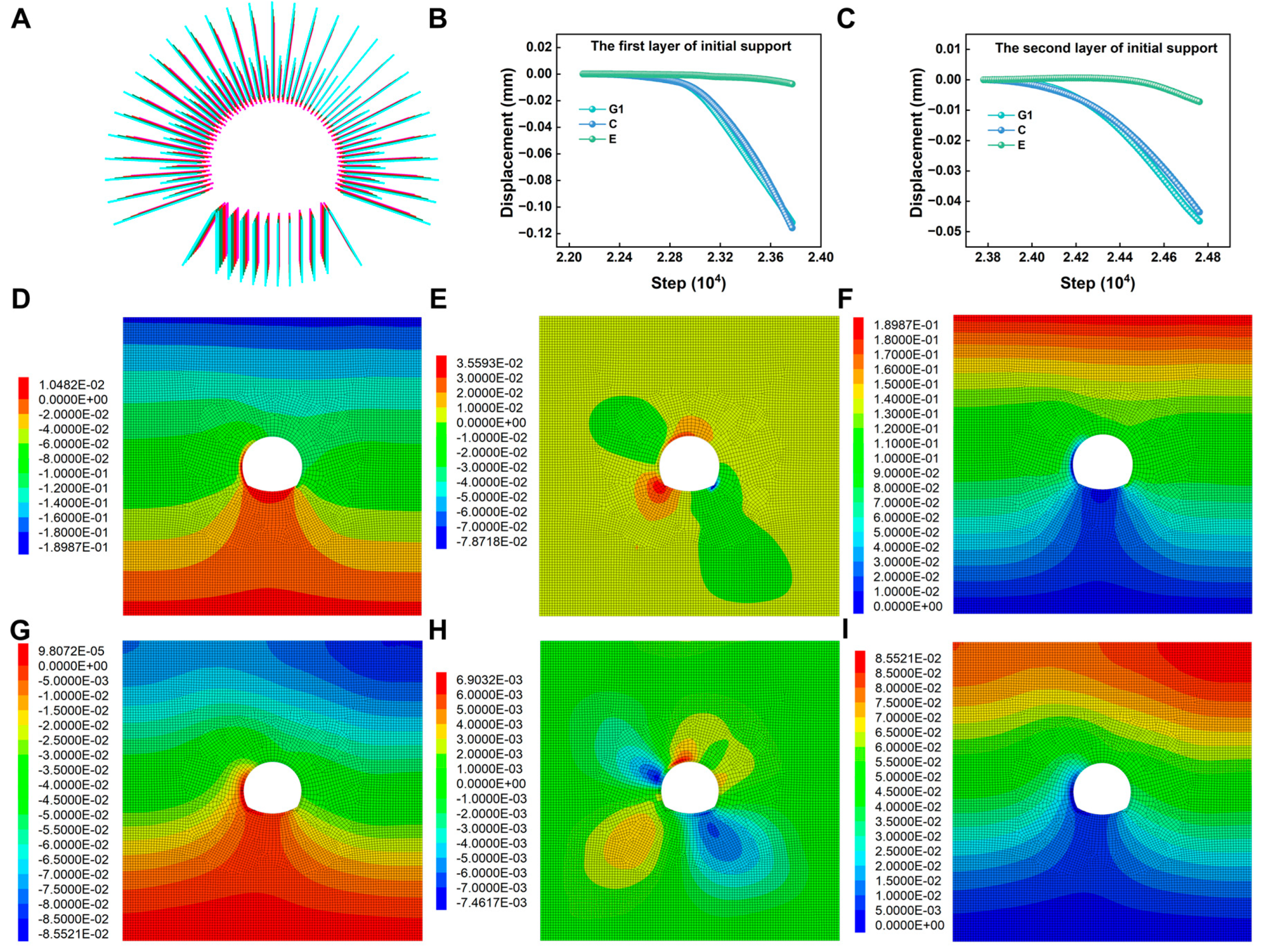
4.2. Numerical Simulation of Tunnel Deformation Support Scheme
5. Conclusions
- (1)
- Considering the influence of stress redistribution caused by tunnel excavation on the measurement results, the maximum principal stresses obtained through in situ stress testing from horizontal and vertical boreholes are determined to be 13.12 MPa and 16.09 MPa, respectively. The maximum horizontal principal stress has a prevailing direction of NE75°, with an angle range of 75° to 85° relative to the axis orientation of the unexcavated tunnel section. The tunnel is situated in an environment of extremely high in situ stress.
- (2)
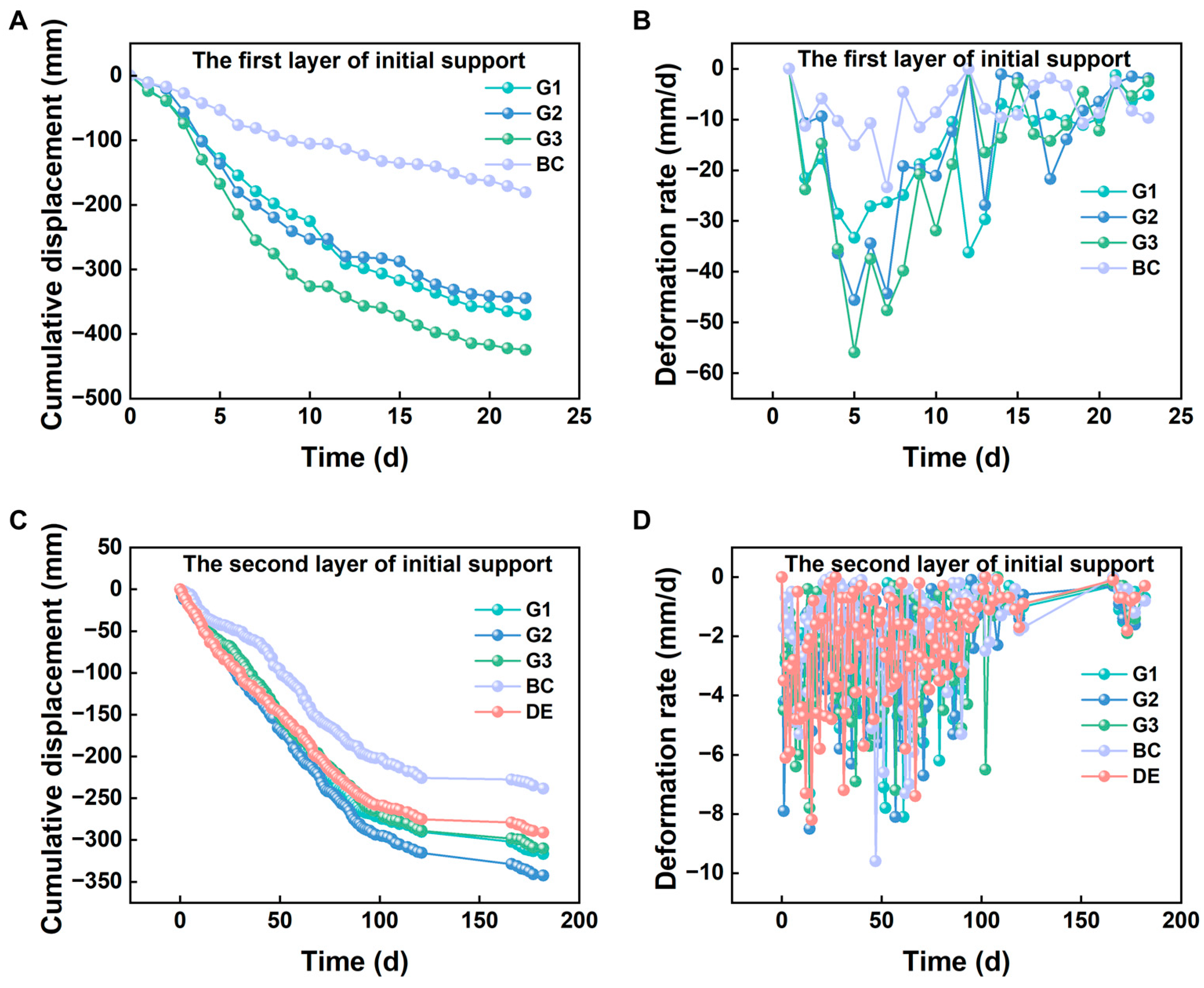
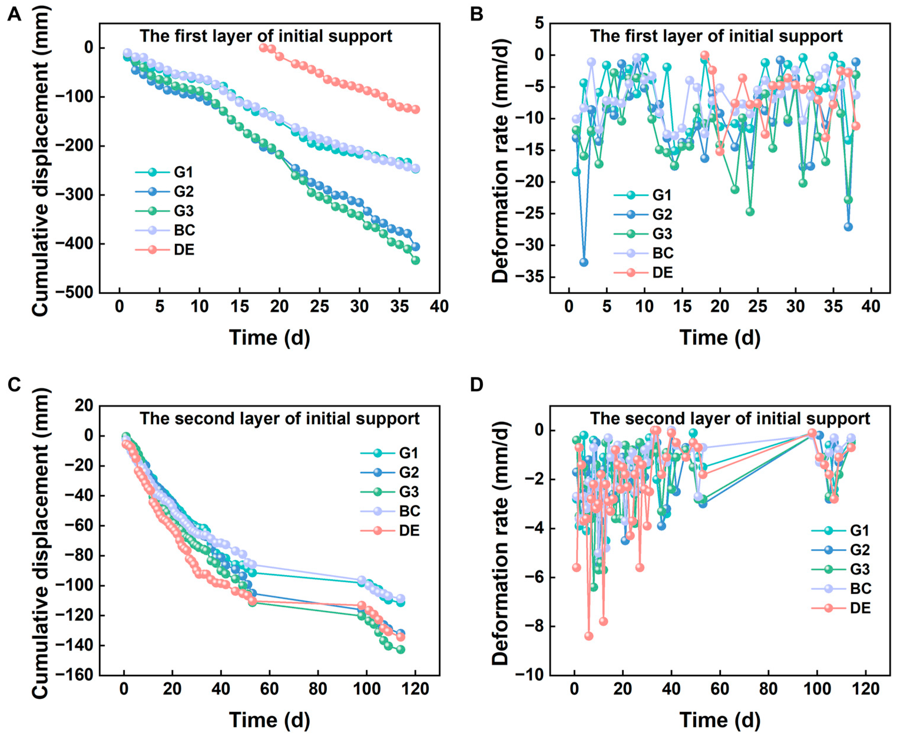
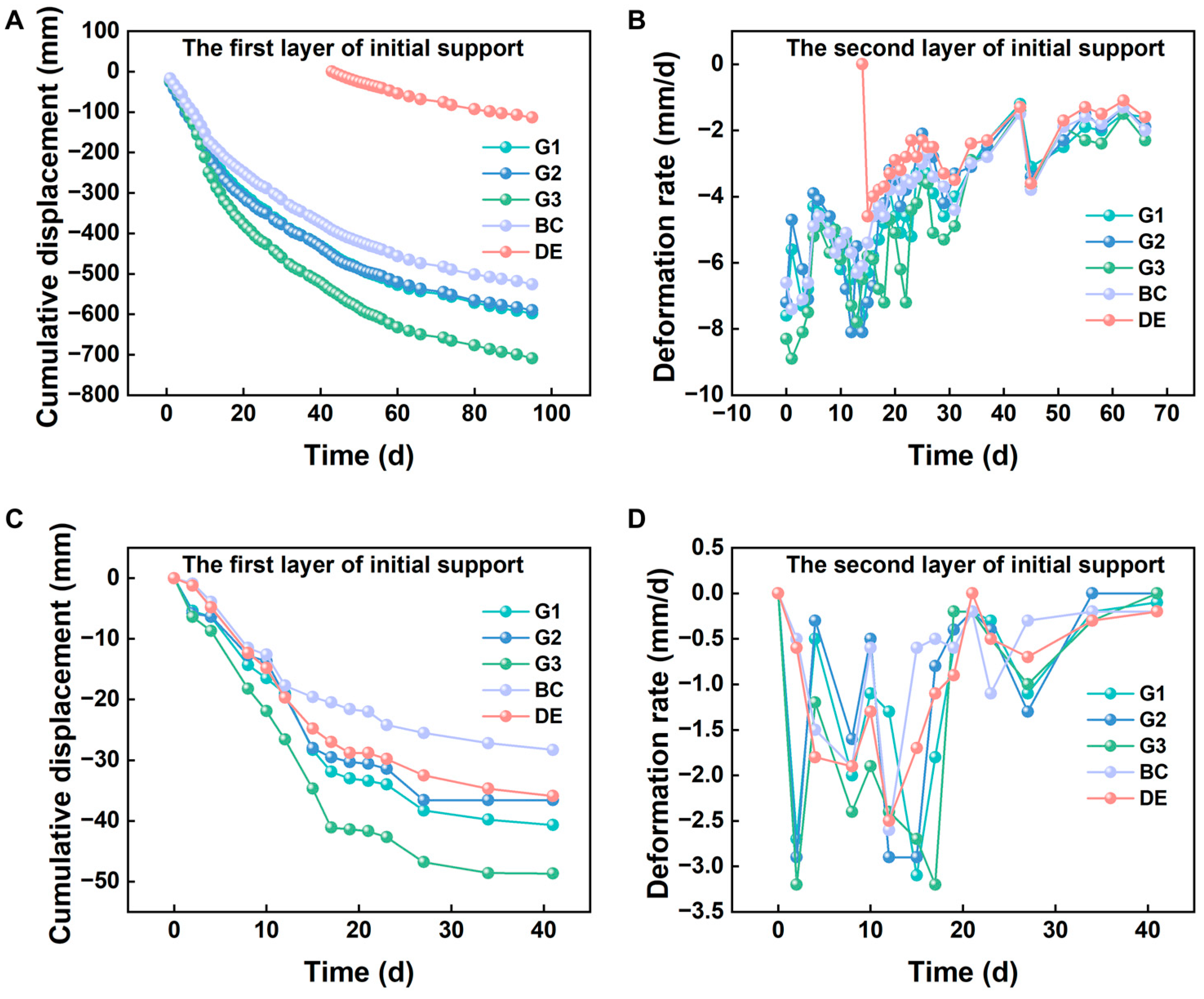
- Extensive deformation and damage occurred within the tunnel near metamorphic mudstone, limestone, and fault zones. The initial support exhibits significant deformation, high deformation rates with slow convergence, prolonged deformation duration, and non-uniform deformation leading to potential structural failure.
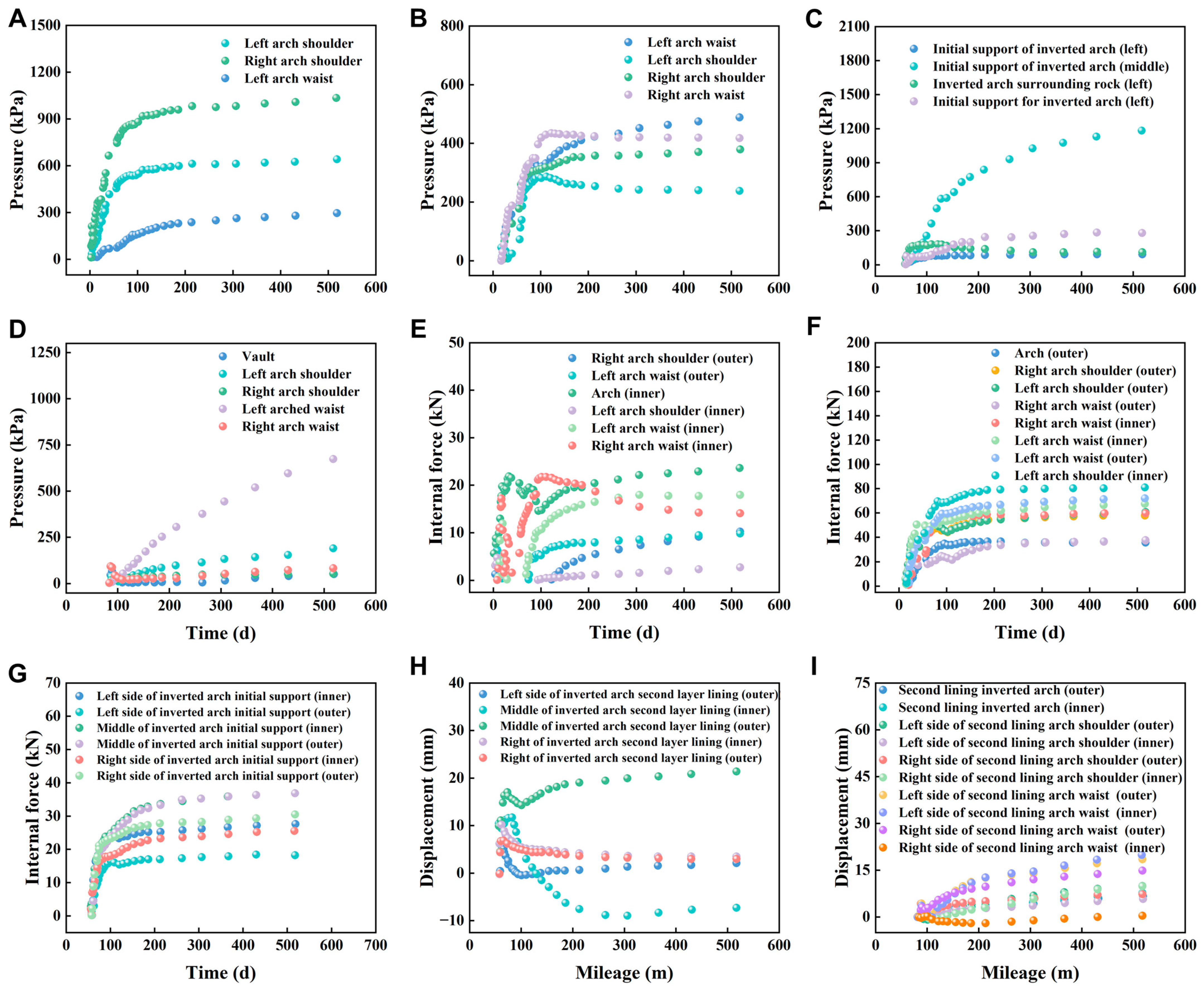
- (3)
- To further verify the cause of tunnel deformation, we can obtain the internal force of tunnel support by monitoring the internal force of the tunnel. The maximum surrounding rock pressure on the right shoulder of the first-layer initial support reached 1000 kPa, while the maximum surrounding rock pressure on the left shoulder of the second-layer initial support reached 500 kPa. Additionally, the maximum surrounding rock pressure in the center of the second-layer initial support invert reached 1200 kPa, and the maximum surrounding rock pressure on the left shoulder of the second-layer lining reached 680 kPa.
- (4)
- A comparison of tunnel deformation support schemes is conducted through field experiments and numerical simulation calculations, indicating that replacing the tunnel upper structure and invert can effectively prevent tunnel deformations.
Author Contributions
Funding
Data Availability Statement
Conflicts of Interest
References
- Cui, G.; Qi, J.; Wang, D. Research on large deformation control technology of tunnels in squeezing rock and its application. Sci. Prog. 2020, 103, 36850420923167. [Google Scholar] [CrossRef] [PubMed]
- Huang, Y.; Zhang, T.; Lu, W.; Wei, H.; Liu, Y.; Xiao, Y.; Zeng, Z. Research on Creep Deformation and Control Mechanism of Weak Surrounding Rock in Super Large Section Tunnel. Geotech. Geol. Eng. 2021, 39, 5213–5227. [Google Scholar] [CrossRef]
- Zhang, J.; Wang, M.; Xi, C. Tunnel Collapse Mechanism and Its Control Strategy in Fault Fracture Zone. Shock Vib. 2021, 2021, 9988676. [Google Scholar] [CrossRef]
- Tao, Z.; Ren, S.; Li, G.; Xu, H.; Luo, S.; He, M. Model test on support scheme for carbonaceous slate tunnel in high geostress zone at high depth. J. Mt. Sci. 2021, 18, 764–778. [Google Scholar] [CrossRef]
- Zhou, Y.; Yang, W.; Zhao, L.; You, Z.; Tian, H.; Zhang, L.; Zhu, Z. Research on reasonable reserved deformation and height-span ratio of a large deformation tunnel section in high geo-stress soft rock near a fault zone: A case study. Bull. Eng. Geol. Environ. 2023, 82, 378. [Google Scholar] [CrossRef]
- Xue, Y.; Zhou, B.; Wu, Z.; Gao, H.; Qiu, D.; Li, G.; Fu, K. Mechanical Properties of Support Forms for Fault Fracture Zone in Subsea Tunnel. Soil Mech. Found. Eng. 2020, 56, 436–444. [Google Scholar] [CrossRef]
- Kou, H.; He, C.; Yang, W.; Wu, F.; Zhou, Z.; Meng, W.; Xiao, L. Asymmetric deformation characteristics and mechanical behavior for tunnels in soft-hard inclined contact strata under high geo-stress: A case study. Bull. Eng. Geol. Environ. 2022, 81, 289. [Google Scholar] [CrossRef]
- Lu, W.; Song, S.; Li, S.; Liang, B.; Li, J.; Luan, Y.; Wang, L.; Sun, H. Study on mechanical properties of composite support structures in TBM tunnel under squeezing soft rock conditions. Tunn. Undergr. Space Technol. 2024, 144, 105530. [Google Scholar] [CrossRef]
- Wu, F.; He, C.; Yang, W.; Kou, H.; Chen, Z.; Wang, F.; Meng, W. Engineering behavior of soft rock tunnels in mountainous areas under multiple hazard inducers: A case study of the Jiuzhaigou-Mianyang Expressway. Bull. Eng. Geol. Environ. 2022, 81, 305. [Google Scholar] [CrossRef]
- Zeng, C.; Zhou, Y.; Zhang, L.; Mao, D.; Bai, K. Study on overburden failure law and surrounding rock deformation control technology of mining through fault. PLoS ONE 2022, 17, e0262243. [Google Scholar] [CrossRef]
- Chen, Z.; He, C.; Yang, W.; Guo, W.; Li, Z.; Xu, G. Impacts of geological conditions on instability causes and mechanical behavior of large-scale tunnels: A case study from the Sichuan–Tibet highway, China. Bull. Eng. Geol. Environ. 2020, 79, 3667–3688. [Google Scholar] [CrossRef]
- Zhao, W.; Gao, H.; Chen, W.; Liu, J.; Peng, W.; Zhou, S. Effects of the friction coefficient and location of the dislocation surface of an active fault on the mechanical response of a freeway tunnel. Environ. Earth Sci. 2023, 82, 288. [Google Scholar] [CrossRef]
- Zhang, C.; Zhu, Z.; Wang, S.; Shi, C.; Li, W. Seismic response and deformation mechanism of near-fault deep tunnels in a strong earthquake area. Acta Geotech. 2023, 18, 4847–4869. [Google Scholar] [CrossRef]
- Li, T.; Chen, Z.; Zhou, Z.; Bao, Y. In situ stress distribution law of fault zone in tunnel site area based on the inversion method with optimized fitting conditions. Front. Earth Sci. 2023, 10, 1031985. [Google Scholar] [CrossRef]
- Qian, D.; Zhang, N.; Pan, D.; Xie, Z.; Shimada, H.; Wang, Y.; Zhang, C.; Zhang, N. Stability of Deep Underground Openings through Large Fault Zones in Argillaceous Rock. Sustainability 2017, 9, 2153. [Google Scholar] [CrossRef]
- Li, D.; Du, S.; Zhang, C.; Mao, D.; Ruan, B. Time-Dependent Deformation Behavior of Completely Weathered Granite Subjected to Wetting Immersion. Rock Mech. Rock Eng. 2021, 54, 6373–6391. [Google Scholar] [CrossRef]
- Ma, K.; Zhao, Y.; Yang, T.; He, R.; Hou, J.; Liu, Y.; Liu, H.; Ma, Q.; Zhang, W. The influence of backfilling of a caved zone and magma intrusion-type faults on surface deformation in a metal mine caused by sublevel caving mining. Int. J. Rock Mech. Min. Sci. 2024, 175, 105677. [Google Scholar] [CrossRef]
- Yang, X.; Ming, W.; Zhang, W.; Zhu, C.; Mao, Y.; Wang, X.; He, M.; Tao, Z. Support on Deformation Failure of Layered Soft Rock Tunnel under Asymmetric Stress. Rock Mech. Rock Eng. 2022, 55, 7587–7609. [Google Scholar] [CrossRef]
- Xu, Y.; Zhang, E.; Luo, Y.; Zhao, L.; Yi, K. Mechanism of Water Inrush and Controlling Techniques for Fault-Traversing Roadways with Floor Heave Above Highly Confined Aquifers. Mine Water Environ. 2020, 39, 320–330. [Google Scholar] [CrossRef]
- Zhou, R.; Weng, X.; Li, L.; Guo, Y.; Chen, S.; Huang, X. Excavation-induced deformation and stress responses of a highway tunnel in fault fracture rock zone with high geo-stress: A case study of Xiangjunshan tunnel. Environ. Earth Sci. 2024, 83, 145. [Google Scholar] [CrossRef]
- Huo, S.S.; Tao, Z.G.; He, M.C.; Xu, C.; Wang, F.N.; Lv, Z.Y. Physical model test of NPR anchor cable-truss coupling support system for large deformation tunnel in fault fracture zone. Tunn. Undergr. Space Technol. 2024, 152, 105939. [Google Scholar] [CrossRef]
- Fangtian, W.; Cun, Z.; Shuaifeng, W.; Xiaogang, Z.; Shenghua, G. Whole section anchor–grouting reinforcement technology and its application in underground roadways with loose and fractured surrounding rock. Tunn. Undergr. Space Technol. 2016, 51, 133–143. [Google Scholar] [CrossRef]
- Cui, J.; Wang, W.; Yuan, C.; Cao, L.; Guo, Y.; Fan, L. Study on Deformation Mechanism and Supporting Countermeasures of Compound Roofs in Loose and Weak Coal Roadways. Adv. Civ. Eng. 2020, 2020, 1–13. [Google Scholar] [CrossRef]
- Tao, Z.; Cao, J.; Yang, L.; Guo, A.; Huang, R.; Yang, X.; Yuan, D.; Hou, L. Study on Deformation Mechanism and Support Measures of Soft Surrounding Rock in Muzhailing Deep Tunnel. Adv. Civ. Eng. 2020, 2020, 1–14. [Google Scholar] [CrossRef]
- Sun, X.; Zhao, C.; Tao, Z.; Kang, H.; He, M. Failure mechanism and control technology of large deformation for Muzhailing Tunnel in stratified rock masses. Bull. Eng. Geol. Environ. 2021, 80, 4731–4750. [Google Scholar] [CrossRef]
- Cao, C.; Shi, C.; Lei, M.; Yang, W.; Liu, J. Squeezing failure of tunnels: A case study. Tunn. Undergr. Space Technol. 2018, 77, 188–203. [Google Scholar] [CrossRef]
- Wang, Y.; Gu, Y.; Liu, J. A domain-decomposition generalized finite difference method for stress analysis in three-dimensional composite materials. Appl. Math. Lett. 2020, 104, 106226. [Google Scholar] [CrossRef]
- Kabir, H.; Aghdam, M.M. A generalized 2D Bézier-based solution for stress analysis of notched epoxy resin plates reinforced with graphene nanoplatelets. Thin-Walled Struct. 2021, 169, 108484. [Google Scholar] [CrossRef]


| Position | Hole Depth (m) | Maximum Principal Stress (MPa) | Minimum Principal Stress (MPa) | Direction of Breaking (°) |
|---|---|---|---|---|
| Horizontal hole | 34 | 13.12 | 9.78 | 46 |
| Vertical hole | 42.6 | 16.09 | 10.88 | NE75 |
| Project | Initial Support | Secondary Lining | Deformation Allowance (mm) | |||||||||
|---|---|---|---|---|---|---|---|---|---|---|---|---|
| Shotcrete | Bolt | Reinforcing Mesh (cm) | Steel Frame Spacing (cm) | Arche/Wall (cm) | Inverted Arch (cm) | |||||||
| Material | Arche/Walls (cm) | Inverted Arch (cm) | Specifications | Location | Length (m) | Distance (m × m) | ||||||
| Before optimization | C25 | 31/29 | 29 | φ25 | Arches/walls | 4 | 1.0 × 1.2 | φ8@150 × 150 (Arches/walls) | 60 | 70 | 90 | 500 |
| After optimization | C25 | 31/29 | 60 | φ32 | Arches/walls | 4.5/9/12 | 1.0 × 1.2/1.2 × 1.2 | φ8@150 × 150 bilayer (Arches/walls) | 60 | 70 | 70 | 500 |
| Category | Young’s Modulus (GPa) | Poisson’s Ratio | Bulk Density (KN/m3) | Cohesive Force (MPa) | Internal Friction Angle (°) |
|---|---|---|---|---|---|
| Strongly weathered mudstone sandstone | 2.20 | 0.33 | 23.00 | 0.30 | 35.00 |
| Anchor rod | 200.00 | 0.20 | 78.50 | N/A | N/A |
| The first layer of initial support | 32.05 | 0.20 | 22.00 | N/A | N/A |
| The second layer of initial support | 32.03 | 0.20 | 22.00 | N/A | N/A |
| Lining | 31.50 | 0.20 | 25.00 | N/A | N/A |
Disclaimer/Publisher’s Note: The statements, opinions and data contained in all publications are solely those of the individual author(s) and contributor(s) and not of MDPI and/or the editor(s). MDPI and/or the editor(s) disclaim responsibility for any injury to people or property resulting from any ideas, methods, instructions or products referred to in the content. |
© 2024 by the authors. Licensee MDPI, Basel, Switzerland. This article is an open access article distributed under the terms and conditions of the Creative Commons Attribution (CC BY) license (https://creativecommons.org/licenses/by/4.0/).
Share and Cite
Zheng, X.; Huang, F.; Wang, S.; Xu, W. Research on the Mechanism of Loose Deformation in Weak Fracture Zone Tunnel Surrounding Rock and Support Control. Buildings 2024, 14, 2506. https://doi.org/10.3390/buildings14082506
Zheng X, Huang F, Wang S, Xu W. Research on the Mechanism of Loose Deformation in Weak Fracture Zone Tunnel Surrounding Rock and Support Control. Buildings. 2024; 14(8):2506. https://doi.org/10.3390/buildings14082506
Chicago/Turabian StyleZheng, Xin, Feng Huang, Sheng Wang, and Wenxuan Xu. 2024. "Research on the Mechanism of Loose Deformation in Weak Fracture Zone Tunnel Surrounding Rock and Support Control" Buildings 14, no. 8: 2506. https://doi.org/10.3390/buildings14082506