Article

Experimental and Theoretical Study on Tensile Mechanical Properties of GFRP–Steel Composite Bars

1
School of Civil and Transportation Engineering, Guangdong University of Technology, Guangzhou 510006, China
2
Shenzhen Branch of China Construction Technology Group Co., Ltd., Shenzhen 518000, China
3
Guangdong Zhongdu Construction Group Co., Ltd., Lianjiang 524499, China
4
Huace Engineering Testing Co., Ltd., Guangzhou 510320, China
*
Author to whom correspondence should be addressed.
Buildings 2024, 14(8), 2513; https://doi.org/10.3390/buildings14082513
Submission received: 24 July 2024 / Revised: 12 August 2024 / Accepted: 13 August 2024 / Published: 15 August 2024
(This article belongs to the Section Building Materials, and Repair & Renovation)

Abstract

:
Glass-fiber-reinforced polymer (GFRP)–steel composite bar, a novel building material, is a promising longitudinal reinforcement for marine engineering in harsh environments. Previous research has primarily focused on altering individual parameters to assess their influence on the performance of composite bars, lacking a systematic and in-depth exploration. In this paper, the tensile properties of composite bars have been investigated by adequate experimental testing considering the type of inner steel bar and the thickness of the GFRP layer. Results show that although composite bars undergo elasticity, hardening, and failure stages under tensile loading, due to differences in interfacial bonding forces, the ultimate failure mode for composite bars with HPB300 inner steel bars is relative slippage, while for those with HRB400 inner steel bars, it is fracturing. While ensuring that composite bars have good initial elastic modulus and durability, it is preferable for the thickness of the external GFRP layer to be as small as possible. However, the thickness of the external GFRP layer of composite bars should not be less than 2 mm to prevent misalignment of the inner steel bars, which can negatively impact the tangent modulus during the hardening stage and the ultimate tensile strength. Furthermore, a stress–strain constitutive model for this composite bar was developed and validated. This model offers a universal framework for accurately representing the mechanical properties of the material across a wide range of research parameters.

1. Introduction

Steel bar corrosion is one of the main problems affecting the durability and safety of reinforced concrete structures [1,2,3]. In recent decades, scholars have conducted extensive and in-depth research to find effective solutions [4,5]. The solutions proposed over time can be broadly categorized into two types. One is replacing the material of the reinforcement, such as using stainless steel bars or fiber-reinforced polymer (FRP) bars, while the other is providing surface protection for the steel bar, such as galvanization or epoxy coating [6,7,8].
The main advantages of FRP bars are high strength, low weight, and good corrosion resistance [9,10,11,12]. However, the further application of FRP bars is limited for their low elastic modulus and high cost [13,14]. Stainless steel bars have high tensile and compressive strength as well as good corrosion resistance and ductility, but have a higher cost than FRP bars [15,16]. In addition, after studying different types of protective layers for steel bars, it was found that although galvanization and epoxy coatings can partially inhibit corrosion, they cannot fully meet the long-term corrosion resistance requirements [17].
Wu et al. [18,19] proposed a novel FRP–steel composite bar to address the respective drawbacks of FRP and steel bars. These composite bars comprise an external layer of FRP and an inner steel bar, thereby amalgamating the advantageous properties of both materials [20,21]. Researchers Dong-WooSeo et al. [22] fabricated three different types of composite bars: (a) GFRP crust with a steel rod in the core; (b) GFRP crust with steel wires dispersed over the cross-section; and (c) GFRP crust with a steel bar in the core. The experiments showed that the stress–strain curves of these three types of composite bars all exhibit a bilinear characteristic, with the steel ratio and cross-sectional type being the main factors affecting the elastic modulus. Compared to pure GFRP bars, as the steel ratio increases, the elastic modulus of the composite bar can increase by up to 250%, but the tensile strength tends to decrease when the steel/fiber ratio is around 0.5. By incorporating an inner steel bar, the composite bars effectively address the issues of low elastic modulus and brittle failure associated with pure GFRP bars. Additionally, the composite bars not only exhibit significant yielding behavior [23,24,25], but also maintain post-yield stiffness [26,27] due to the superior protection provided to the internal steel reinforcement by the external FRP layer.
Presently, research into the mechanical properties of FRP–steel composite bars remains at a relatively nascent stage, characterized by a deficiency in systematic and comprehensive investigation. Most of the studies focused on altering individual parameters to assess their influence on the performance of composite bars. For example, Zhao et al. [28] investigated composite bars utilizing hot-rolled plain bars as inner steel components and identified that both diameter and surface treatment significantly impacted the bond strength at the interface between the composite bars and concrete. Further, Zhang [29] conducted tensile tests on steel fiber-reinforced carbon/glass hybrid composite bars. The findings revealed that composite bars with a steel fiber replacement ratio of 20% and a carbon/glass ratio of 1:4 demonstrated a maximum elastic modulus of 90.2 GPa, surpassing that of GFRP bars by 77%. Cui Yihua et al. [30] proposed a hybrid fiber-reinforced composite bar, which involves creating a new type of composite bar by mixing steel fibers and glass fibers in specific proportions. Mechanical performance was analyzed through tensile testing experiments, and the results showed that, compared to GFRP bars, the hybrid fiber-reinforced composite bar exhibits excellent ductility and a high elastic modulus (reaching 71% of that of steel reinforcement). Moreover, the elastic modulus of the composite bars demonstrated effective enhancement with increasing fiber volume fraction. However, systematic research on the effect of the inner steel bar types and the external FRP layer thickness on the tensile performance of composite bars remains lacking. In addition, the interface interaction between the inner steel and external FRP layer of the composite bar is yet to be studied for its effect on the mechanical performance. Therefore, systematically studying these key issues is necessary to advance the engineering applications of composite bars [31,32].
This study selected composite bars with glass-fiber-reinforced polymer (GFRP) as the external layer and HPB300 (hot-rolled plain bars) and HRB400 steel bars (hot-rolled ribbed bars) as the inner steel bars. Experimental and theoretical research were conducted to investigate the tensile mechanical properties of the manufactured GFRP–steel composite bars. This study extensively investigated the effect of different types of inner steel bars and thickness of the external GFRP layer on the mechanical performance indicators of the composite bars via a series of experiments. Further, a stress–strain constitutive model of the GFRP–steel composite bars was constructed. This study provides rich experimental data support for theoretical research in the field of GFRP–steel composite bars and a more reliable basis and guidance for its engineering practical application.

2. Experimental Program

2.1. Materials and Specimens

This study investigated composite reinforcement made from GFRP materials and steel produced through industrial processes (Figure 1). As shown in Figure 2, the industrial production process of GFRP–steel composite bars includes cleaning the steel surface, applying the resin to the fiber cloth, wrapping with the fiber cloth, winding the fiber bundle, and curing and forming. HPB300 and HRB400 steel bars with diameters of 10 mm are used as the inner steel bars. The GFRP is used as the external layer of the composite bars (thickness of layer = 2, 3, 4, and 5 mm). The rationale behind selecting these specific GFRP layer thicknesses is based on their common use in practical engineering applications, their ability to effectively test the mechanical performance variations, and the feasibility of their production using existing processes. For subsequent analysis, composite bars with HPB300 and HRB400 inner steel bars are hereafter referred to as ‘PC composite bars’ and ‘RC composite bars’, respectively. This paper sampled the same batch of base materials used for making PC composite bars and RC composite bars and conducted tensile performance tests on three samples each of HPB300 steel bars, HRB400 steel bars, and GFRP bars. The tensile performance tests were conducted according to the standards GBT 30022-2013, ‘Test method for basic mechanical properties of fiber reinforced polymer bar’ [33] and GBT 228.1-2021, ‘Metallic materials—Tensile testing—Part 1: Method of test at room temperature’ [34]. The tests were performed using a universal testing machine (model WAW-1000). The relevant mechanical properties of the composite bar base materials, listed in Table 1, represent the mean values of the three samples tested.
The effects of the type of inner steel bars and thickness t of the external GFRP layer are considered for the tensile test specimens. Given the types of inner steel bars and the thickness of the external layer, a total of 8 experimental groups are designed for this study. Each group consists of four identical specimens, totaling 32 specimens, as listed in Table 2. All specimens have a length of 800 mm. For the sake of convenience, the tensile test specimens were named based on the type of inner steel bar and the thickness of the external FRP layers. For example, in the groups listed in Table 2, ‘PC2’ indicates that HPB300 steel bars were used as the inner steel bars, and ‘2’ indicates that the thickness of the external GFRP layer was 2 mm (i.e., the diameter of the composite bar was 14 mm). Further, ‘RC5’ indicates that HRB400 steel bars were used as the inner steel bars, and ‘5’ indicates that the thickness of the external GFRP layer was 5 mm (i.e., the diameter of the composite bar was 20 mm).
Directly loading the composite bars during tension tests can cause premature cracking at the ends of the external GFRP layer because of their inherent brittleness, which can lead to the composite bars failing prematurely. To prevent this, tensile mechanical performance tests were performed by reinforcing the ends of the composite bars with steel sleeves and an epoxy injection, as indicated in Figure 3. The reinforcement method can be divided into four steps:
(1)
Fabricate a steel sleeve with a length of 250 mm and an inner diameter larger than the diameter of the composite bar by 6 mm.
(2)
Inject an adhesive (Sikadur-330CN gel) into the steel sleeve until it fills the steel sleeve.
(3)
Insert the composite bar vertically into the center of the steel sleeve and remove any excess adhesive overflowing from the steel sleeve.
(4)
Reinforce the other end in the same manner once the adhesive is cured completely.

2.2. Test Methods

The mechanical tests for composite bars refer to GB/T 228.1-2021, ‘Tensile test of metallic materials at room temperature’ [34]. The mechanical performances of the composite bars were tested using a universal testing machine produced by Changchun Lige Material Testing Technology Co., Ltd., Changchun, China (model WAW-1000) as shown in Figure 4. For testing the tensile mechanics, the composite bars were loaded at a speed of 2.0 mm/min until the external GFRP layer on the composite bar ruptured or the inner steel bars broke, at which point the test was terminated. During the test, the load data of the composite bars were collected and recorded using a force sensor system built into the universal testing machine. The deformations of the specimens were recorded using an extensometer with a gauge length of 50 mm.

3. Results and Discussions

3.1. Tensile Failure Mode

The tensile test results showed that the failure process of the GFRP–steel composite bars with different parameters was consistent. The failure process can be divided into three stages:
(1)
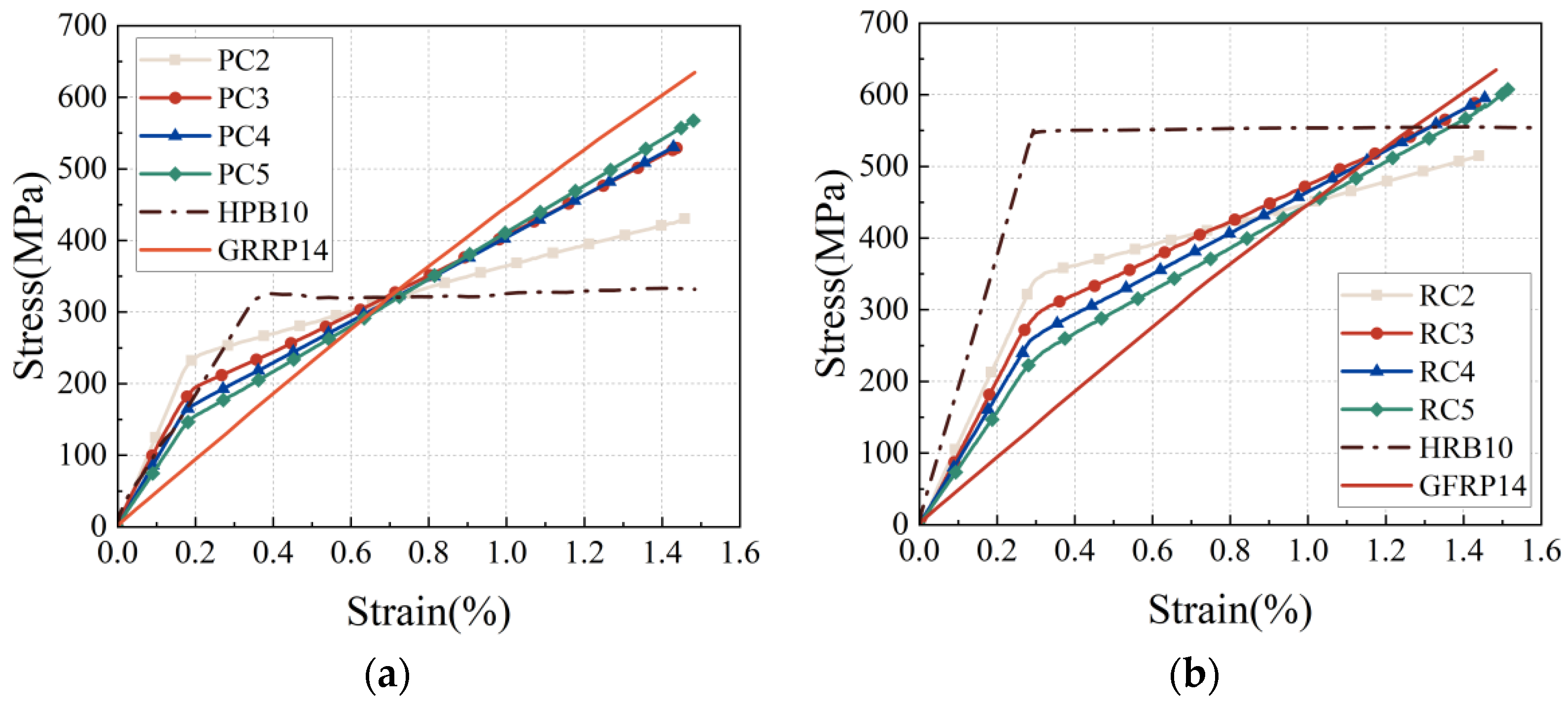
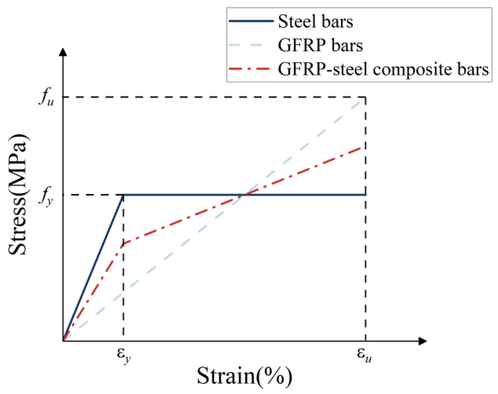
Elastic stage: The inner steel bars and external GFRP layer deform cooperatively, sharing the tensile load. The deformation of the composite bars increases at a relatively uniform rate with a gradual increase in the applied tensile load.
(2)
Elastic–plastic hardening stage after the inner steel bars of the composite bars yield: As the tensile load continues to increase until it reaches the yield strength of the inner steel bars, the inner steel bars can no longer bear the increase in the tensile load [16], and the increase in the tensile load is borne by the external GFRP layer. In the elastic–plastic hardening stage, the composite bar deformation exhibits a faster growth rate than that in the elastic stage.
(3)
Evolution stage of the composite bar failure: A slight sound from the fiber bundle fracture is emitted at a weak cross-section of the specimen once the tensile load causes the composite bars to reach their maximum tensile strength. Subsequently, the external GFRP layer undergoes fracture at the weak cross-section of the working section, indicating the beginning of the evolution stage of the composite bar failure. At this point, the load decreases sharply until the composite bars reach the final failure state.
The final failure modes are different for the PC and RC composite bars. The failure mode of the latter is fracturing (Figure 5a), which can be attributed to the strong mechanical interlocking and significant interfacial bonding force between the HRB400 steel bars and the GFRP. The final failure mode of the PC composite bars is relative slippage, as illustrated in Figure 5b. This can be attributed to the weaker interfacial bonding force between the external GFRP layer and HPB300 steel bars.

3.2. Stress–Strain Curve Analysis

Figure 6 shows the stress–strain curves of all specimens. In this study, the slope of the stress–strain curve in the elastic stage is defined as the initial elastic modulus. The nominal yield point is defined as the point of the sudden strain rate change in the composite bars (the yield point of the inner steel bars). The slope of the curve decreases significantly in the second half after the nominal yield point of the composite bars. The tangent modulus of the hardening stage is defined as the slope of the linear curve in the second half of the composite bar. Similar to certain polymers [35], the stress–strain curves of the composite bars exhibit clear bilinear characteristics because, at the nominal yield point, the main load-bearing material changes from the inner steel bars to the external GFRP layer. Subsequently, the external GFRP layer fails when the composite bars reach their ultimate tensile strength, thereby leading to a significant decrease in the load. At this point, the tensile load is borne by the yielding inner steel bars. The stress–strain curves of the PC composite bars are presented in Figure 6. ‘HPB10’ represents an HPB300 steel bar with a diameter of 10 mm, and ‘GFRP14’ represents a GFRP bar with a diameter of 14 mm.
Composite bars transitioning from the normal working conditions to tensile failure fully utilize the strength reserve of their constituent materials. The composite bars utilize the high tensile strength of GFRP and the high elastic modulus and good plasticity of steel bars. The stress–strain curve of PC composite bars passes through the intersection of the inner steel bars’ and GFRP bars’ curves. The stress–strain curve of RC composite bars passes below the intersection of the inner steel bars’ and GFRP bars’ curves because the inner steel bars and external GFRP layer no longer deform in coordination in the elastic–plastic hardening stage after the yielding of the inner steel bar in RC composite bars, and the external GFRP layer is damaged by the ribs of the inner steel bars during the tensile process. This decreases the tangent modulus of the hardening stage of RC composite bars. As shown in Figure 7, if the inner steel bars are not centered, uneven forces can act on the specimen, which can lead to the premature local failure of the specimen. For RC composite bars (such as the RC2 specimen), the ribs of the inner steel bars will make the thinner side of the unevenly distributed external GFRP layer more prone to failure.
Table 3 presents the tensile test results of the GFRP–steel composite bars. The average values of various mechanical performance indicators of the composite bars with different parameters, including the initial elastic modulus Ei (GPa), tangent modulus of the hardening stage EII (GPa), nominal yield strength fy (MPa), and ultimate tensile strength fu (MPa), are presented.

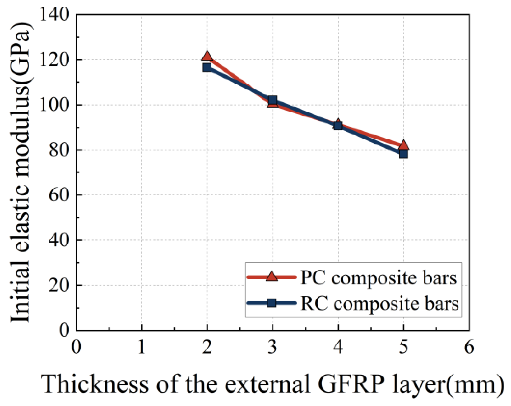
3.3. Initial Tensile Elastic Modulus

Figure 8 illustrates the effect of the thickness of the external GFRP layer on the initial elastic modulus. The initial elastic modulus of the specimens from all experimental groups decreases gradually with an increasing thickness of the external GFRP layer because the initial elastic modulus of the composite bars depends on the elastic modulus of both constituent materials. The elastic moduli of the inner steel bars used in this test are significantly higher than that of the external GFRP layer. The cross-sectional area subjected to force in the composite bars increases with an increase in the thickness of the external GFRP layer, whereas the ratio of the area of the steel bars to that of the external GFRP layer decreases. The proportion of the steel bars in the composite bars plays a crucial role in determining the initial elastic modulus. In GFRP–steel composite-bar-reinforced concrete structures, composite bars with a higher proportion of steel bars impart a higher initial stiffness to the structure. The deformation of composite-bar-reinforced concrete structures can be effectively controlled by designing an appropriate area ratio between the steel bars and the external GFRP layer of the composite bars [36].

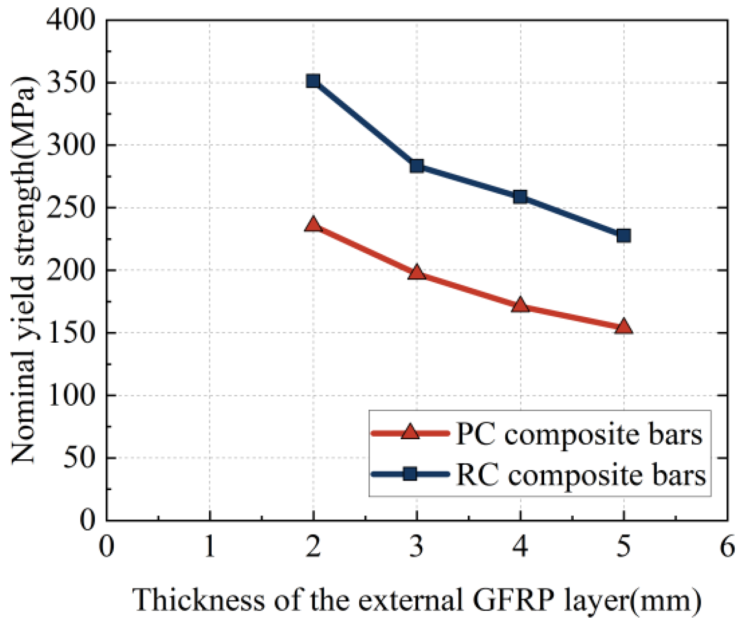
3.4. Nominal Tensile Yield Strength

Figure 9 shows the effect of the thickness of the external GFRP layer on the nominal yield strength of composite bars. The nominal yield strength of the composite bars decreases with increasing thickness of the external GFRP layer. For the same thickness of the external GFRP layer, the nominal yield strength of the RC composite bars is higher than that of the PC composite bars. The experimental results confirm that the nominal yield strength of the composite bars is closely related to the type of inner steel bar and thickness of the external GFRP layer.

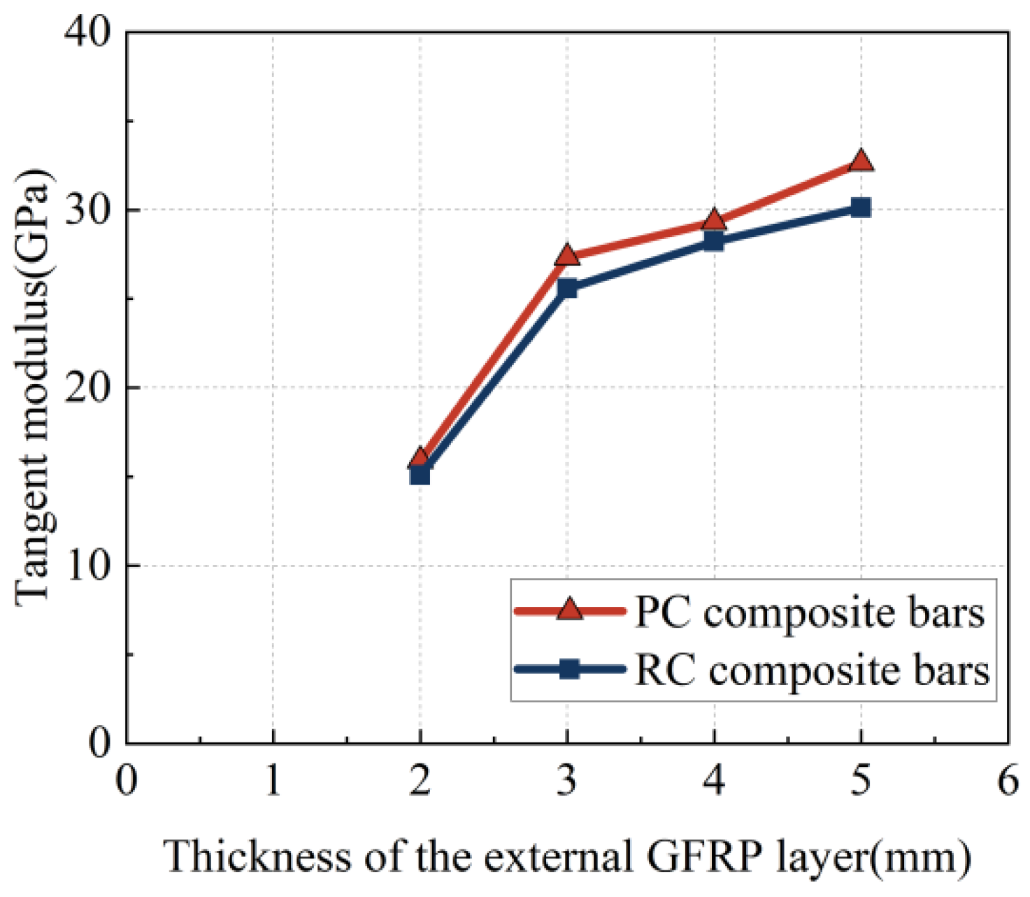
3.5. Tangent Modulus of the Hardening Stage

Figure 10 illustrates the effect of varying the thickness of the external GFRP layer on the tangent modulus of the hardening stage of the composite bars. After the inner steel bars of the composite bars yield, the tangent modulus of the hardening stage of the composite bars increases with an increase in the thickness of the external GFRP layer. According to the experimental results, the thickness of the external GFRP layer has a critical effect on the tangent modulus of the hardening stage of the composite bars. Thicker external GFRP layers result in a higher tangent modulus of the hardening stage. When the thickness of the external GFRP layer is 2 mm, the tangent modulus of the hardening stage is exceptionally low, which can be attributed to the uneven thickness of the external GFRP layer (misalignment of the inner steel bars). Such manufacturing defects can significantly affect the mechanical properties of the composite bars [27]. Further, this adverse effect is pronounced in specimens with an external GFRP layer with a thickness of 2 mm. The external GFRP layer of the RC composite bars is damaged by the steel ribs of the inner steel bars during tensile testing. The tangent modulus of the hardening stage of the RC composite bars is lower than that of the corresponding PC composite bars. Thus, the thickness of the external GFRP layer is a crucial factor that affects the mechanical properties of composite bars and holds significant value in the design of composite-bar-reinforced concrete structures.

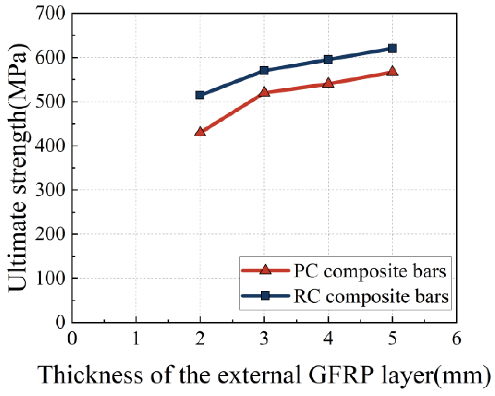
3.6. Ultimate Tensile Strength

Figure 11 illustrates the effect of varying the thickness of the outer GFRP layer on the ultimate tensile strength of the composite bars. For an external GFRP layer with a thickness greater than 3 mm, the ultimate tensile strength stabilizes and increases with an increase in the thickness of the external GFRP layer. This is because, in the elastic–plastic hardening stage, the increase in the tensile load is borne by the external GFRP layer. The cross-sectional force area of the composite bars increases with an increase in the thickness of the external GFRP layer, whereas the ratio of the area of the steel bars to the area of the external GFRP layer decreases. The ultimate tensile strength of the composite bars is relatively low when the thickness of the external GFRP layer is 2 mm because certain areas of the external GFRP layer may become extremely thin if the inner steel bars are not centered. These manufacturing defects can decrease the mechanical properties of the external GFRP layer, resulting in a decline in the overall mechanical performance of the composite bars. Therefore, the data from the specimens with an external GFRP layer that has a thickness of 2 mm are not meaningful for the subsequent establishment of theoretical models. In practical applications of composite bar production, good performance cannot be ensured by focusing on only the thickness of the external GFRP layer. The manufacturing process of composite bars significantly affects their mechanical properties. Considering that the external GFRP layer in composite bars plays a role in protecting the inner steel bars, the design of the thickness of the external GFRP layer must comprehensively consider the characteristics of other constituent materials in the composite bars and consider the effect of manufacturing process defects.

4. Tensile Constitutive Model of GFRP–Steel Composite Bars

4.1. Stress–Strain Constitutive Model

During the experimental process, before the failure of the external GFRP layer, the synergistic performance between the inner steel bars and the external GFRP layer of the GFRP–steel composite bars was good. Therefore, coordination between the deformation of the external GFRP layer and the inner steel bars was assumed at the same cross-section. Based on this assumption, a schematic stress–strain diagram of the GFRP–steel composite bars is shown in Figure 12. The stress–strain constitutive relationship expression for the GFRP–steel composite reinforcement under tension can be derived as shown in Equations (1)–(3).
σ = ε E s A s + E f A f A ε y E s A s + ε E f A f A         0 ε < ε y   ε y ε ε u
E I = E s A s + E f A f A                 0 ε < ε y
E I I = E f A f A                 ε y ε ε u
where σ represents the stress value of the composite bars, ε represents the strain of the composite bars, and εy represents the yielding strain of the composite bars, i.e., the yielding strain of the inner steel bars. Further, EI represents the initial elastic modulus of the composite bars in the elastic stage, and EII represents the tangent modulus of the hardening stage of the composite bars after yielding of the inner steel bars. Further, As and Es represent the area and elastic modulus of the inner steel bars, respectively; Af, Ef, and εu represent the area, elastic modulus, and ultimate strain of the external GFRP layer, respectively; and A represents the total area of the composite bars.
The nominal yield strain of the PC composite bars depended on the yield strain of the inner steel bars. Therefore, the yield strain of the GFRP–steel composite bars when calculating the theoretical value of the nominal yield strength fy, that is, the yield strain of the inner steel bars εy, should be used in Equation (1). In the elastic–plastic hardening stage of the composite bars, the inner steel bar no longer bore an increase in the tensile load. The tensile load was borne by the external GFRP layer [16]. Therefore, the ultimate strain εu of the external GFRP layer should be used in Equation (1) when calculating the theoretical value of ultimate tensile strength fu. The values of εy and εu were obtained through tensile tests recorded by a 50 mm gauge length extensometer, as shown in Table 4.

4.2. Analysis of Theoretical Calculation Results

According to Equations (1)–(3), EI, EII, fy, and fu are calculated for different sets of specimens. The theoretical values are compared with the test values, and the relative errors between them are analyzed. The mechanical performances of specimens PC2 and RC2 are significantly affected by the uneven thickness of the external layer, which results in test values of the mechanical properties that were considerably lower than the theoretical values. Therefore, this section does not discuss the results for specimens PC2 and RC2. The comparison results of the theoretical and test values for the composite bars are shown in Table 5 and Table 6. The tables indicate that the relative errors of the theoretical values for relevant mechanical properties are controlled within 5%, indicating good agreement between the theoretical and test results for the composite bars. This validates the assumption that the deformation coordination between the inner steel bars and external GFRP layer in the same section is established before the external GFRP layer fractures. The proposed GFRP–steel composite bar stress–strain constitutive model accurately predicted its tensile performance.

5. Conclusions

In this paper, we thoroughly investigated the effects of the type of inner steel bar and the thickness of the GFRP layer on the mechanical properties of GFRP–steel composite bars. Key mechanical performance indicators, including the initial elastic modulus, yield strength, tangent modulus during the hardening stage, and ultimate strength, were analyzed. Based on the results, the following conclusions can be drawn:
(1)
During the tensile process until failure, the composite bars underwent three stages: elasticity, hardening, and failure. The failure started with a sudden fracture of the external GFRP layer. The final failure modes are different for the PC and RC composite bars. The failure mode of the RC composite bars is fracturing, while the final failure mode of the PC composite bars is relative slippage for the weaker interfacial bonding force between the external GFRP layer and HPB300 steel bars.
(2)
When composite bars are used as longitudinal tensile bars, the thickness of the external GFRP layer should be as small as possible, while also ensuring that the composite bars have a good initial elastic modulus and durability. However, the designed thickness of the external GFRP layer for the composite bars should not be less than 2 mm because the misalignment of the inner steel bars caused by manufacturing process defects can have a highly detrimental effect on the tangent modulus of the hardening stage and ultimate tensile strength.
(3)
This study established a constitutive model for the stress–strain behavior of composite bars, which aligns well with the stress–strain obtained from the tests.
This study provides rich experimental data support for theoretical research in the field of GFRP–steel composite bars and a more reliable basis and guidance for its engineering practical application.

6. Future Research Prospects

This paper conducted theoretical analysis and experimental research on the basic mechanical properties of composite bars, providing a reference for the engineering application of composite bars. However, the current research results are still limited and have certain shortcomings. Future research directions can proceed from the following aspects:
(1)
This paper studied the basic mechanical properties of composite bars in normal environments. Corrosion resistance is a particularly prominent feature of composite bars. Future studies can investigate the changes in basic mechanical properties of composite bars under harsh environmental conditions.
(2)
This paper studied composite bars with GFRP as the external layer. Future research can investigate the basic mechanical properties of composite bars using other fiber materials as the external layer, such as BFRP, CFRP, and hybrid fiber.
(3)
In practical engineering, structures are often subjected to repeated loads, and this paper only studied the effects of axial tensile loads. Therefore, it is necessary to study the mechanical behavior of composite bars under repeated tensile loading.

Author Contributions

Conceptualization, W.C.; Software, L.L.; Validation, Z.W.; Formal analysis, B.W.; Investigation, F.L., J.H. and L.L.; Resources, H.Z. (Huanyu Zhu); Data curation, H.Z. (Hao Zhen) and F.L.; Writing—original draft, H.Z. (Hao Zhen); Writing—review & editing, Z.X.; Supervision, W.C. and Z.W.; Project administration, B.W., H.L. and Z.X.; Funding acquisition, W.C. and Z.X. All authors have read and agreed to the published version of the manuscript.

Funding

This work was supported by the Natural Science Foundation of Guangdong Province (in China) [grant numbers 2024B1515020028]; the National Natural Science Foundation of China [grant numbers 12032009, 12072080]; and the Special Fund Project for Science and Technology Innovation Strategy of Guangdong Province (in China) [grant number pdjh2024a137].

Data Availability Statement

The original contributions presented in the study are included in the article, further inquiries can be directed to the corresponding author.

Conflicts of Interest

Author Baolong Wu was employed by the company Shenzhen Branch of China Construction Technology Group Co., Ltd. Authors Hongming Li and Zhichao Wu were employed by the company Guangdong Zhongdu Construction Group Co., Ltd. Author Jian Huang was employed by the company Huace Engineering Testing Co., Ltd. The remaining authors declare that the research was conducted in the absence of any commercial or financial relationships that could be construed as a potential conflict of interest.

References

  1. Poursaee, A. Corrosion of Steel in Concrete Structures; Woodhead Publishing: Sawston, UK, 2016. [Google Scholar] [CrossRef]
  2. Bhargava, K.; Ghosh, A.K.; Mori, Y.; Ramanujam, S. Model for cover cracking due to rebar corrosion in RC structures. Eng. Struct. 2006, 28, 1093–1109. [Google Scholar] [CrossRef]
  3. Triantafyllou, G.G.; Rousakis, T.C.; Karabinis, A.I. Effect of patch repair and strengthening with EBR and NSM CFRP laminates for RC beams with low, medium and heavy corrosion. Compos. Part B Eng. 2018, 133, 101–111. [Google Scholar] [CrossRef]
  4. Xiong, Z.; Mai, G.; Pan, Z.; Chen, Z.; Jian, J.; Wang, D.; Ling, Z.; Li, L. Synergistic effect of expansive agents and glass fibres on fatigue bending performance of seawater sea sand concrete. Constr. Build. Mater. 2024, 421, 135665. [Google Scholar] [CrossRef]
  5. Zhen, H.; Xiong, Z.; Song, Y.; Li, L.; Qiu, Y.; Zou, X.; Chen, B.; Chen, D.; Liu, F.; Ji, Y. Early mechanical performance of glass fibre-reinforced manufactured sand concrete. J. Build. Eng. 2024, 83, 108440. [Google Scholar] [CrossRef]
  6. Moodley, H.; Afshan, S.; Crump, D.; Kashani, M.M. Testing and numerical modelling of circular stainless steel reinforced concrete columns. Eng. Struct. 2024, 304, 117607. [Google Scholar] [CrossRef]
  7. Liu, Z.; Wang, H.; Yang, L.; Du, J. Research on mechanical properties and durability of flax/glass fiber bio-hybrid FRP composites laminates. J. Compos. Struct. 2022, 290, 115566. [Google Scholar] [CrossRef]
  8. Zhu, H.; Xiong, Z.; Song, Y.; Zhou, K.; Su, Y. Effect of Expansion Agent and Glass Fiber on the Dynamic Splitting Tensile Properties of Seawater–Sea-Sand Concrete. Buildings 2024, 14, 217. [Google Scholar] [CrossRef]
  9. Guo, R.; Xian, G.; Li, C.; Huang, X.; Xin, M. Effect of fiber hybridization types on the mechanical properties of carbon/glass fiber reinforced polymer composite rod. J. Mech. Adv. Mater. Struct. 2022, 29, 6288–6300. [Google Scholar] [CrossRef]
  10. Guo, R.; Xian, G.; Li, C.; Hong, B.; Huang, X.; Xin, M.; Huang, S. Water uptake and interfacial shear strength of carbon/glass fiber hybrid composite rods under hygrothermal environments: Effects of hybrid modes. J. Polym. Degrad. Stab. 2021, 193, 109723. [Google Scholar] [CrossRef]
  11. Zhang, M.; Guan, Z.; Ren, Y.; Wang, H. Multi-scale study on the mechanical properties of pultruded GFRP laminates. J. Fibers Polym. 2023, 24, 2133–2146. [Google Scholar] [CrossRef]
  12. Wu, G.; Ren, Y.; Du, J.; Wang, H.; Zhang, X. Mechanical properties and failure mechanism analysis of basalt-glass fibers hybrid FRP composite bars. Case Stud. Constr. Mater. 2023, 19, e02391. [Google Scholar] [CrossRef]
  13. Saxena, M.; Pappu, A.; Sharma, A.; Haque, R.; Wankhede, S. Composite Materials from Natural Resources: Recent Trends and Future Potentials; IntechOpen: London, UK, 2011. [Google Scholar] [CrossRef]
  14. Pleimann, L.G. Strength, Modulus of Elasticity, and Bond of Deformed FRP Rods. In Advanced Composites Materials in Civil Engineering Structures; ASCE: Reston, VA, USA, 1991; pp. 99–110. [Google Scholar]
  15. Guo, J.; Chan, T.-M.; Wang, Y. Test, modelling and design of a demountable stainless steel bar connection system for precast concrete pavements. Eng. Struct. 2023, 301, 117231. [Google Scholar] [CrossRef]
  16. Xu, J.; Wu, Z.; Cao, Q.; Yu, R.C. Eccentric compression behavior of seawater and sea sand concrete columns reinforced with GFRP and stainless steel bars. Eng. Struct. 2023, 291, 116486. [Google Scholar] [CrossRef]
  17. Aihua, L.; VandenBerg, G. A study and research of stainless steel in concrete structure. Archit. Technol. 2000, 2, 105–107. [Google Scholar] [CrossRef]
  18. Wu, G.; Sun, Z.Y.; Wu, Z.S.; Luo, Y.B. Mechanical Properties of Steel-FRP Composite Bars (SFCBs) and Performance of SFCB Reinforced Concrete Structures. Adv. Struct. Eng. 2012, 15, 625–636. [Google Scholar] [CrossRef]
  19. Sun, Z.-Y.; Wu, G.; Wu, Z.-S.; Zhang, J. Nonlinear Behavior and Simulation of Concrete Columns Reinforced by Steel-FRP Composite Bars. J. Bridge Eng. 2013, 19, 220–234. [Google Scholar] [CrossRef]
  20. Nanni, A.; Henneke, M.J.; Okamoto, T. Tensile properties of hybrid rods for concrete reinforcement. Constr. Build. Mater. 1994, 8, 27–34. [Google Scholar] [CrossRef]
  21. Saikia, B.; Thomas, J.; Ramaswamy, A.; Rao, K.S.N. Performance of hybrid rebars as longitudinal reinforcement in normal strength concrete. Mater. Struct. 2005, 38, 857–864. [Google Scholar] [CrossRef]
  22. Seo, D.W.; Park, K.T.; You, Y.J.; Lee, S.Y. Experimental investigation for tensile performance of GFRP-Steel hybridized rebar. Adv. Mater. Sci. Eng. 2016, 2016, 9401427. [Google Scholar] [CrossRef]
  23. Han, S.; Zhou, A.; Ou, J. Relationships between interfacial behavior and flexural performance of hybrid steel-FRP composite bars reinforced seawater sea-sand concrete beams. Compos. Struct. 2021, 277, 114672. [Google Scholar] [CrossRef]
  24. Tang, Y.; Sun, Z.; Wu, G. Compressive Behavior of Sustainable Steel-FRP Composite Bars with Different Slenderness Ratios. Sustainability 2019, 11, 1118. [Google Scholar] [CrossRef]
  25. Ge, W.; Chen, K.; Guan, Z.; Ashour, A.; Lu, W.; Cao, D. Eccentriccompression behaviour of concrete columns reinforced with steel-FRP composite bars. Eng. Struct. 2021, 238, 112240. [Google Scholar] [CrossRef]
  26. Zhou, Y.; Zheng, Y.; Pan, J.; Sui, L.; Xing, F.; Sun, H.; Li, P. Experimental investigations on corrosion resistance of innovative steel-FRP composite bars using X-ray microcomputed tomography. Compos. B Eng. 2019, 161, 272–284. [Google Scholar] [CrossRef]
  27. Li, H.; Liu, F.; Pan, Z.; Li, H.; Wu, Z.; Li, L.; Xiong, Z. Use of supplementary cementitious materials in seawater–sea sand concrete: State-of-the-art review. Constr. Build. Mater. 2024, 425, 136009. [Google Scholar] [CrossRef]
  28. Zhao, D.; Pan, J.; Zhou, Y.; Sui, L.; Ye, Z. New types of steel-FRP composite bar with round steel bar inner core: Mechanical properties and bonding performances in concrete. Constr. Build. Mater. 2020, 242, 118062. [Google Scholar] [CrossRef]
  29. Zhang, T.; Gao, D. Tensile behavior analysis and prediction of steel fiber-reinforced-carbon/glass hybrid composite bars. J. Build. Eng. 2022, 64, 105669. [Google Scholar] [CrossRef]
  30. Cui, Y.; Noruziaan, B.; Lee, S.; Chang, M.; Tao, J. Hybrid high modulus and high toughness composite reinforcement. J. Compos. Mater. 2006, 23, 93–98. [Google Scholar] [CrossRef]
  31. Dhakal, R.P.; Maekawa, K. Modeling for postyield buckling of reinforcement. J. Struct. Eng. 2002, 128, 1139–1147. [Google Scholar] [CrossRef]
  32. Bae, S.; Mieses, A.M.; Bayrak, O. Inelastic buckling of reinforcing bars. J. Struct. Eng. 2005, 131, 314–321. [Google Scholar] [CrossRef]
  33. GB/T 30022-2013; Test Method for Basic Mechanical Properties of Fiber Reinforced Polymer Bar. Standardization Administration of China: Beijing, China, 2013.
  34. GB/T 228.1-2021; Metallic Materials-Tensile Testing Part 1: Method of Test at Room Temperature. Standardization Administration of China: Beijing, China, 2021.
  35. Khani, M.; Materzok, T.; Eslami, H.; Gorb, S.; Müller-Plathe, F. Water uptake by gecko β-keratin and the influence of relative humidity on its mechanical and volumetric properties. J. R. Soc. Interface 2022, 19, 372. [Google Scholar] [CrossRef]
  36. Pan, Z.; Liu, F.; Li, H.; Li, X.; Wang, D.; Ling, Z.; Zhu, H.; Zhu, Y. Performance Evaluation of Thermal Insulation Rubberized Mortar Modified by Fly Ash and Glass Fiber. Buildings 2024, 14, 221. [Google Scholar] [CrossRef]
Figure 1. GFRP–steel composite bars: (a) PC composite bars; (b) RC composite bars.
Buildings 14 02513 g001
Figure 2. Industrial production process of composite reinforcement.
Buildings 14 02513 g002
Figure 3. Composite bars with end strengthening.
Buildings 14 02513 g003
Figure 4. Setup of tensile test.
Buildings 14 02513 g004
Figure 5. Final failure of GFRP–steel composite bars: (a) RC composite bars; (b) PC composite bars.
Buildings 14 02513 g005
Figure 6. Stress–strain curve of GFRP–steel composite bars: (a) PC composite bars; (b) RC composite bars.
Buildings 14 02513 g006
Figure 7. Misalignment of the inner steel bar.
Buildings 14 02513 g007
Figure 8. Effect of the thickness of the external GFRP layer on initial elastic modulus.
Buildings 14 02513 g008
Figure 9. Effect of the thickness of the external GFRP layer on the nominal yield strength.
Buildings 14 02513 g009
Figure 10. Effect of the thickness of the external GFRP layer on the tangent modulus of the hardening stage.
Buildings 14 02513 g010
Figure 11. Effect of the thickness of the external GFRP layer on the ultimate tensile strength.
Buildings 14 02513 g011
Figure 12. Stress–strain relationship of GFRP–steel composite bars.
Buildings 14 02513 g012
Table 1. Basic mechanical properties of composite bar materials.
MaterialsDiameter
(mm)
Tensile Yield Strength
(MPa)
Tensile Elastic Modulus
(Gpa)
Tensile Strength
(Mpa)
HPB30010324.58191.64427.81
HRB40010552.87185.71623.89
GFRP14\43.08637.92
Table 2. Specimens for the test.
Test TypeGroupInner Steel Bart (mm)Number
Tensile testPC2HPB30024
PC3HPB30034
PC4HPB30044
PC5HPB30054
RC2HRB40024
RC3HRB40034
RC4HRB40044
RC5HRB40054
Table 3. Tensile test results of the mechanical properties of GFRP–steel composite bars.
SpecimenEI (GPa)EII (GPa)fy (MPa)fu (MPa)
PC14-1119.1316.89230.01430.12
PC14-2120.0315.9241.16423.18
PC14-3123.7615.33243.49434.23
PC14-4121.8715.52227.59432.92
Average121.1915.91235.56430.11
Standard deviation1.780.66.874.27
PC16-197.8426.05201.43524.34
PC16-299.527.84197.89511.92
PC16-3102.4127.72198.36560.78
PC16-4101.2527.75200.56532.36
Average100.2527.34199.56532.35
Standard deviation1.730.751.4817.96
PC18-191.1829.62170.04556.1
PC18-292.2929.43168.61520.03
PC18-390.0228.81172.65514.32
PC18-491.1529.38173.1530.15
Average91.1629.31171.1530.15
Standard deviation0.80.31.8516.02
PC20-182.433.96152.61569.06
PC20-279.231.29152.84562.89
PC20-382.3931.68154.31569.03
PC20-482.6533.63155.92567.54
Average81.6632.64153.92567.13
Standard deviation1.421.171.332.52
RC14-1116.7213.96355.8521.44
RC14-2119.0416.95348.08540.38
RC14-3114.7914.31349.72480.85
RC14-4115.5315.14351.32515.53
Average116.5215.09351.23514.55
Standard deviation1.611.162.8821.51
RC16-1104.1725.81283.59609.29
RC16-2102.1425.71280.97570.32
RC16-3101.825.23285.22573.33
RC16-4100.0525.57283.22585.66
Average102.0425.58283.25584.65
Standard deviation1.460.221.5215.34
RC18-188.5727.62259.67581.39
RC18-290.4928.04255.67603.12
RC18-391.528.89265.21602.26
RC18-490.6128.27253.37594.3
Average90.2928.21258.48595.27
Standard deviation1.070.464.498.72
RC20-177.7630.39226.87611.42
RC20-276.5630.12224.47610.99
RC20-379.6529.78229.25593.19
RC20-478.6730.22230.09611.88
Average78.1630.12227.67606.87
Standard deviation1.140.222.197.9
Table 4. Corresponding strain of materials.
Specimenεy (%)εu (%)
HPB100.219.96
HRB100.299.24
GFRP10\1.49
Table 5. Comparison of test values and theoretical values of EI and fy.
SpecimenEI (GPa)fy (MPa)
Test ValueTheoretical ValueError (%)Test ValueTheoretical ValueError (%)
PC3100.25101.11−0.86199.56202.22−1.33
PC491.1688.932.44171.1177.86−3.95
PC581.6680.221.76153.92160.44−4.24
RC3102.0498.793.18 283.25296.38−4.64
RC490.2987.103.53258.48261.30−1.09
RC578.1678.74−0.74227.67236.21−3.75
Average error (%)1.56Average error (%)3.17
Table 6. Comparison of test values and theoretical values of EII and fu.
SpecimenEII (GPa)fu (MPa)
Test ValueTheoretical ValueError (%)Test ValueTheoretical ValueError (%)
PC327.2226.253.56532.35540.87−1.60
PC429.3129.78−1.62530.15562.07−6.02
PC532.6432.311.01567.13577.24−1.78
RC325.5826.25−2.63584.65608.78−4.13
RC428.2129.78−5.58595.27615.73−3.44
RC530.132.31−7.34 606.87620.70−2.28
Average error (%)−2.10Average error (%)−3.21
Disclaimer/Publisher’s Note: The statements, opinions and data contained in all publications are solely those of the individual author(s) and contributor(s) and not of MDPI and/or the editor(s). MDPI and/or the editor(s) disclaim responsibility for any injury to people or property resulting from any ideas, methods, instructions or products referred to in the content.

