Abstract
In complex underground conditions, the excavation of deep foundation pits has a significant impact on the deformation of retaining structures and nearby subway stations. To investigate the influence of deep excavation on the deformation of adjacent structures, a three-dimensional numerical model of the foundation pit, existing subway station, and tunnel structure was established using FLAC 3D software, based on the Shenzhen Bay Super Headquarters C Tower foundation pit project. The study analyzed the deformation characteristics of retaining structures, adjacent subway stations, and tunnels during different stages of deep excavation, and the accuracy of the numerical simulation results was validated through field monitoring data. The results indicate that during the excavation process of the foundation pit, the lateral horizontal displacement of the retaining structure is generally small, with a typical “concave inward” lateral deformation curve; the horizontal displacement value of the contiguous wall section is less than that of the interlocking pile section. The bending moments of the retaining structure show a distribution pattern with larger values in the middle and smaller values at the top and bottom of the pit, with a relatively uniform distribution of internal support forces. The maximum displacement of the nearby subway station is 8.75 mm, and the maximum displacement of the subway tunnel is 2.29 mm. The research findings can provide references for evaluating the impact of newly built foundation pits near subway stations and contribute to the rational design and safe construction of new projects.
1. Introduction
With the rapid development of urban infrastructure, urban planning is facing increasingly severe challenges. In the process of urban development, the rise of high-rise buildings has led to more and more deep excavation projects for foundation pits. The excavation process of deep foundation pits inevitably causes widespread unloading of soil [1,2,3], thereby adversely affecting the stability of nearby subway facilities [4,5,6]. Therefore, during the foundation pit excavation process, a reasonable foundation pit support scheme is an important means to reduce soil disturbance and minimize the impact on subway structures [7,8]. By adopting appropriate support structures and construction techniques, it is possible to effectively control soil deformation and settlement, thereby protecting the stability of subway structures.
Predicting the actual engineering effects through numerical models has become an indispensable part of many engineers’ designs, and numerous scholars have explored numerical simulation methods in foundation pit engineering theory and practice. Luo et al. [9] conducted a three-dimensional finite element simulation study on the dewatering of a foundation pit repair for the Shanghai Dongjiao Tunnel, and after comparison, they found that the simulation results were consistent with the actual situation. They believed that three-dimensional finite element numerical simulation could be used to support the optimization design of foundation pit dewatering engineering structures in the Yangtze River Delta region. Yin and Ni [10] studied the foundation pit engineering of Anhui Mingzhu Shopping Plaza through theoretical analysis, field measurements, and numerical simulation. The results showed that the model results obtained by FLAC3D software were generally consistent with the measured data, accurately reflecting the evolution laws of soil pressure and deformation during pit excavation. Additionally, many scholars [11,12,13] have conducted a lot of work on foundation pit deformation or structural design using numerical simulation, validating the accuracy and efficiency of numerical simulation in foundation pit excavation.
In recent years, there has been a greater demand for deeper and larger foundation pit projects, and support structure forms are constantly innovating, striving for a balance between excavation stability and the green economy [14,15]. Therefore, many scholars use numerical calculations to study the performance of relevant structures. Lu and Jiang [16] studied the stress characteristics and support effects of a T-shaped pile support system that can reduce the footprint of foundation pits under symmetric and asymmetric excavation conditions. They discovered the central effect of using a T-shaped pile support system in foundation pits, providing new design ideas for foundation pit projects near subway lines. Han et al. [17] proposed a new type of H-shaped steel support system and conducted on-site monitoring research based on a foundation pit engineering project in Shanghai. They analyzed the pile displacement with construction stage changes and verified the applicability of this new support system. The use of this support system can shorten the construction period, reduce costs, and effectively improve green construction levels. Sun and Li [18] studied the pile–soil interaction, stress changes, and deformation laws of deep foundation pit support systems under pile anchor support systems, providing important references for the information construction of related projects based on the foundation pit project of Nanlishi Road in Xicheng District, Beijing. Tu et al. [19] revealed the spatial and temporal effects of deformation in support structures and their correlation with groundwater levels in deep excavation projects using SMW piles combined with internal support in soft soil areas. These studies have explored the stability of foundation pits during unloading in detail, but further discussion is needed on the disturbance of surrounding underground structures.
Many scholars have also conducted research on the impact of deep foundation pit excavation on subway structures in complex urban environments. Yang et al. [20] used Midas GTS to study the impact of deep foundation pit construction on the deformation and stress of nearby subway stations in soft soil areas, revealing the variation laws of subway station structural deformation and stress and the important influence of foundation pit support structure stiffness and thickness on deformation and stress distribution during foundation pit construction. Niu et al. [21] studied the impact of foundation pit excavation on adjacent subway tunnel deformation through theoretical analysis and numerical simulation based on a foundation pit project near the F1322 fracture zone of Shenzhen Metro Line 5. The research results can provide reference for formulating construction monitoring plans and risk management strategies, thereby promoting the safety of the subway system and the sustainable development of cities. These scholars used numerical simulation methods to explore the impact of foundation pits on existing underground structures [22,23,24,25,26]. These studies ingeniously combined actual engineering with numerical simulation methods, but often only focused on the formation of foundation pit support schemes, lacking comparison with field monitoring data regarding the accuracy of numerical model results. Therefore, to meet the demand for safely, efficiently, and economically constructing deep and large foundation pits, it is necessary to ensure the accuracy of numerical calculations when predicting and controlling the deformation effects of soil disturbance caused by foundation pit excavation on complex existing underground structures.
In this study, a three-dimensional numerical simulation model was established to clarify the degree of influence on nearby subway facilities under different working conditions. After calculation, the internal forces of the supporting structure and the deformation near the foundation pit were obtained. The purpose is to study the deformation impact of a reasonable support scheme on excavation of a foundation pit when facing a nearby existing subway. At the same time, the monitoring data of control points were compared and analyzed with the numerical simulation results to ensure the accuracy and reliability of the calculations. The project environment on which this study is based is complex, with the Hongshuwan South Station and Subway Line 2 nearby, which still poses high requirements for design and construction technology. The relevant solutions can provide experience and references for similar projects.
2. Project Basics
2.1. Overall Layout and Geological Conditions
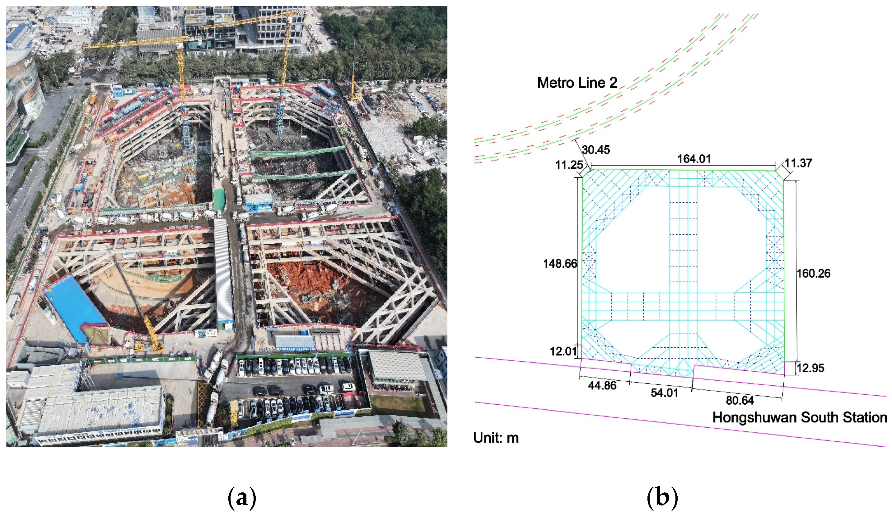
The Shenzhen Bay Super Headquarters C Tower project is located in Nanshan District, Shenzhen, with a total site area of 36,268 square meters. It measures approximately 200 m from north to south and 180 m from east to west, with a total construction area of about 550,000 square meters. The geographical distribution of the project site is shown in Figure 1, with Deep Bay Park Road to the east, Baishi 4th Road to the south, Deep Bay 2nd Road to the west, and Baishi 3rd Road to the north. Subway Line 2 passes through the northwest side of the site, while Subway Lines 9/11 pass through the south side of the site. According to the design, the outdoor floor elevation is approximately 5.15 m, the north side underground basement has three to four floors, and the south side underground basement is temporarily planned for two floors. The estimated depth of the foundation pit is 15–24 m.

Figure 1.
Geographical location (a) picture and (b) map of C tower project site.
This project is located in Nanshan District, Shenzhen, which is a marine alluvial plain area that has been artificially reclaimed. The overlying strata mainly consist of the Quaternary system’s man-made fill layer (Q4ml), marine sediment layer (Q4m), alluvial layer (Q3al+pl), and residual layer (Qel). The surface layer in the reclaimed area is a thick layer of man-made fill, mainly composed of rubble, clay, and gravel, with some areas containing construction debris. The underlying bedrock belongs to the Jurassic system biotite granite ().
2.2. Foundation Pit and Support Overview
The excavation area of the foundation pit for this project is approximately 31,000 square meters, with a depth of approximately 31,000 square meters. The pit has a rectangular outline with a perimeter of about 700 m. The south side of the foundation pit is arranged along the outer wall of the Hongshuwan South Station and the subway entrance and exit, at a distance of 3 m from their outer wall lines. Other sides are arranged according to the red line of land use planning.
Part of the land on the north side of the foundation pit is within the security area of Shenzhen Metro Line 2, and part of the land on the south side is within the security area of Shenzhen Metro Lines 9 and 11. Therefore, before construction, a special safety assessment of the impact on the subway must be conducted. The construction plan must comply with relevant regulations and requirements and draw on the experience of similar projects [27,28] to ensure effective control of the impact on nearby subway tunnels.
The surrounding environment of the foundation pit is complex. Based on the characteristics of the foundation pit and actual construction conditions, the foundation pit support mainly includes support structure systems, vertical and horizontal support systems, and waterproof measures.
The support structure system of this project’s foundation pit adopts an interlocking pile/contiguous wall with internal support type. Between exits C and D, the existing 0.8 m thick contiguous wall of Hongshuwan South Station is used as temporary support for the foundation pit, and the bottom of the pit is reinforced with a grid-like arrangement of high-pressure-jet grouted piles of 700 mm. The remaining sides use interlocking piles for support. Both the interlocking pile (for concrete piles) and contiguous wall are underwater C30 reinforced concrete piles, and the plain piles are underwater C20 plain concrete piles.
Three reinforced concrete internal supports are vertically installed in the foundation pit, with supporting beams connecting to the support structure. The first and third supporting beams are 1000 mm × 1200 mm, the second supporting beam is 1000 mm × 1000 mm. To facilitate future material stacking and construction road layout, the first internal support section in some areas is equipped with a 250 mm thick steel plate for material stacking and construction roads, while the vertical support of the support beam is composed of 1200 pillars + 700 steel pipe with a wall thickness of 16 mm, filled with C30 concrete or steel grating.
Based on safety and economic considerations, as well as local engineering experience, the foundation pit waterproofing design uses interlocking piles or utilizes the existing contiguous wall for waterproofing. High-pressure-jet grouting is used to reinforce the interlocking piles on the south side of the foundation pit between exits C and D. Additionally, a closed drainage ditch is installed at the top and bottom of the foundation pit to block surrounding water and drain accumulated water into the municipal pipes around the pit.
3. Excavation Three-Dimensional Numerical Simulation
Based on the aforementioned project status, this chapter utilizes FLAC 3D 6.0 software and adopts the large deformation Lagrangian numerical simulation method [29] to conduct three-dimensional numerical simulation calculations of the excavation process of the foundation pit at the Shenzhen Bay Super Headquarters Base C Tower project. This is performed to simulate the stress release of the excavation soil and the resulting deformation of the surrounding environment of the foundation pit. The analysis mainly focuses on the stress and deformation of the foundation pit support system, as well as the impact of the excavation construction on the surrounding environment.
3.1. Three-Dimensional Numerical Calculation Model
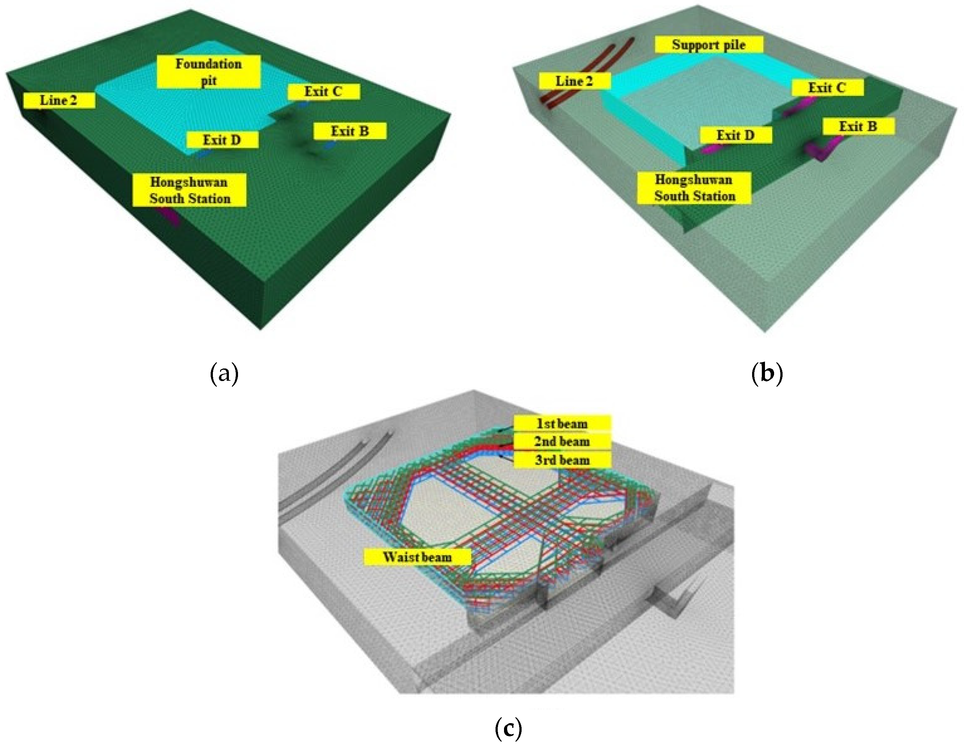
The three-dimensional numerical calculation model before excavation is shown in Figure 2a, modeled using Rhino software and exported as a file format recognized by FLAC 3D through the Griddle plugin. Considering the influence of boundary effects on the accuracy of numerical models, a certain distance is selected between the model boundary and the foundation pit. The length and width of the excavated foundation pit were approximately 200 m and 180 m, respectively. The final dimensions of the model are determined to be 480 m and 375 m, and the perimeter of the foundation pit is selected as a chain constraint restricting the horizontal direction. The bottom of the foundation pit is set as a chain constraint restricting the vertical direction. For units that divide soil, concrete internal supports, subway tunnels, and other structures, appropriate sizes should be used to avoid calculation errors and excessive computational complexity caused by dividing the units. Imported into FLAC 3D, the model comprises 186,733 nodes and 1,043,050 block elements. The underground structure mainly includes the foundation pit support system, Subway Line 2 tunnel, and Hongshuwan South Station, as shown in Figure 2b, with segmented excavation for support, forming three layers of internal support layout, as depicted in Figure 2c.

Figure 2.
Numerical calculation model. (a) Three-dimensional finite element calculation model. (b) Model Structure Layout. (c) Beam element layout.
In the geotechnical numerical calculations, the soil elements use the Mohr–Coulomb model, pile structures use pile elements, tunnel linings use shell elements, the contiguous wall and Hongshuwan South Station structures use initial lining elements, and internal support uses beam elements. The parameters of each soil layer in the model are listed in Table 1. Normal displacement constraints are applied to all vertical boundaries and the base surface of the three-dimensional numerical model.

Table 1.
Physical and mechanical parameters of the soil.
3.2. Pit Excavation Steps and Process
Currently, pit construction simulation analysis and calculations mainly employ the full amount method and incremental method. The full amount method involves loading the total load and boundary conditions at once, ignoring changes in loads and boundary conditions during the construction process. In the incremental method, loads are gradually increased (or decreased) according to the changes in the construction process, and boundary conditions are adjusted accordingly. The entire calculation and analysis process is divided into multiple stages based on the actual construction process, and the final structural internal forces and element stresses and strains are gradually accumulated based on the results of each stage. This analysis and calculation adopt the incremental method.
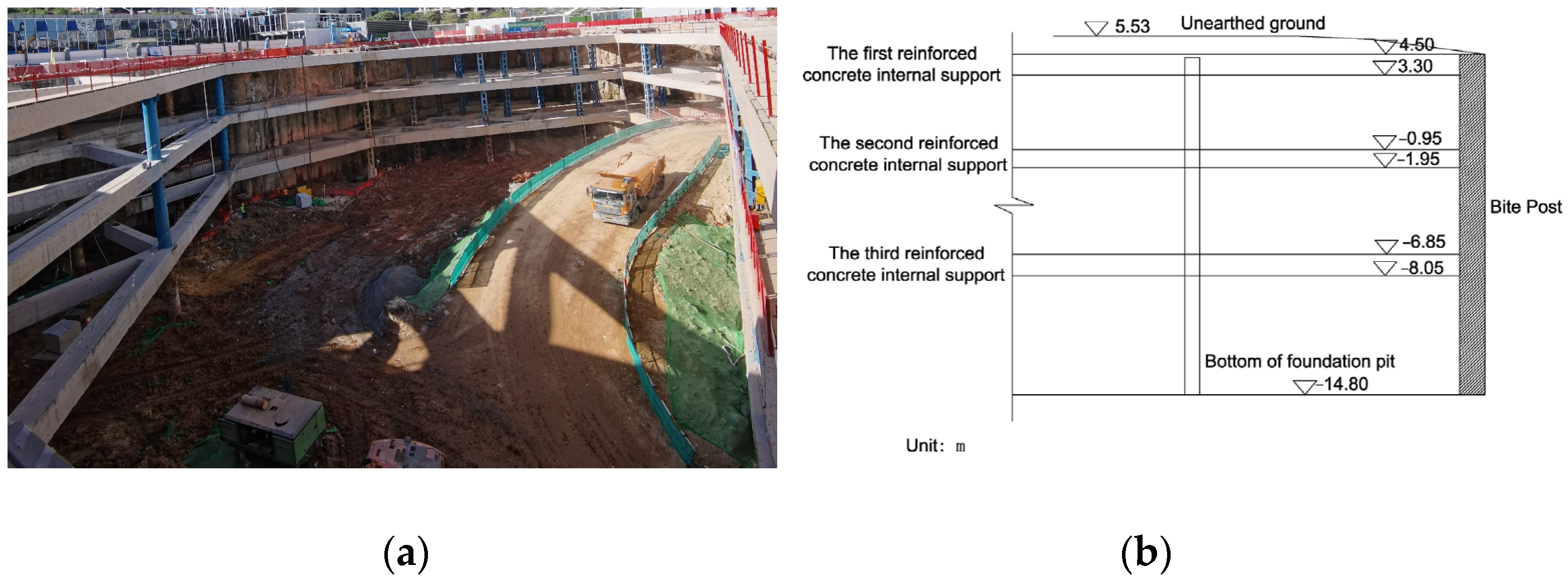
Based on the construction process of the foundation pit and considering the impact on existing tunnel structures, the simulation is divided into two major stages: the first stage establishes the geostress field and constructs the interval tunnel structure, while the second stage is divided into four steps for pit excavation and support, as shown in Table 2. Deformations from stage 1 are reset before excavation. The last column of Table 2 shows the thickness of each excavation step. The excavation photos and schematic diagram are shown in Figure 3a and Figure 3b, respectively.
Table 2.
Calculation and analysis steps.

Figure 3.
(a) Excavation picture and (b) schematic diagram.
4. Pit and Subway Structure Impact Analysis
4.1. Excavation Support Structure Deformation Analysis
Due to the large area and depth of excavation in this project, soft soil layers exist underground, and it is necessary to avoid causing significant deformations to the surrounding subway tunnels and stations. Therefore, a combination of bite piles and existing subway station contiguous walls with reinforced concrete internal supports is used as the support structure, requiring a focus on the stress and deformation of the support structure.
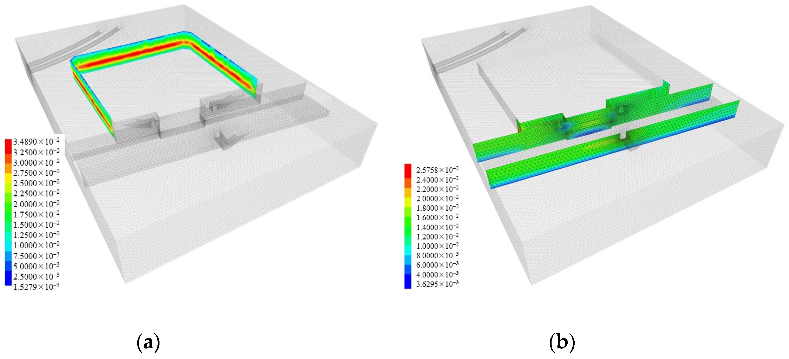
Each pair of construction processes listed in Table 2 generates different displacement effects on the pit support structure. However, for a more practical study of engineering issues, this section focuses on discussing the displacement of the support structure from the end of the fourth excavation step to the bottom of the pit. Figure 3a shows the displacement variation cloud map of the bite piles after pit excavation, while Figure 3b shows the displacement variation cloud map of the contiguous wall after pit excavation.
From Figure 4, it can be observed that during the pit excavation process, the maximum lateral displacement is mainly concentrated in the middle part of the support structure, with smaller displacements on both sides. This is because the bottom of the support structure experiences greater constraints, while the top receives less lateral soil pressure, leading to larger lateral pressure and weaker support constraints in the middle section. As the pit excavation progresses, the maximum lateral horizontal displacement continues to increase, corresponding to increasing depth, while the displacements at the top and bottom of the support structure remain relatively small.
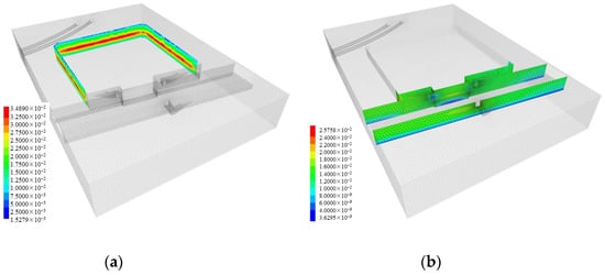
Figure 4.
(a) Displacement of the engaging piles. (b) Displacement of underground diaphragm wall during excavation to the bottom of the foundation pit.
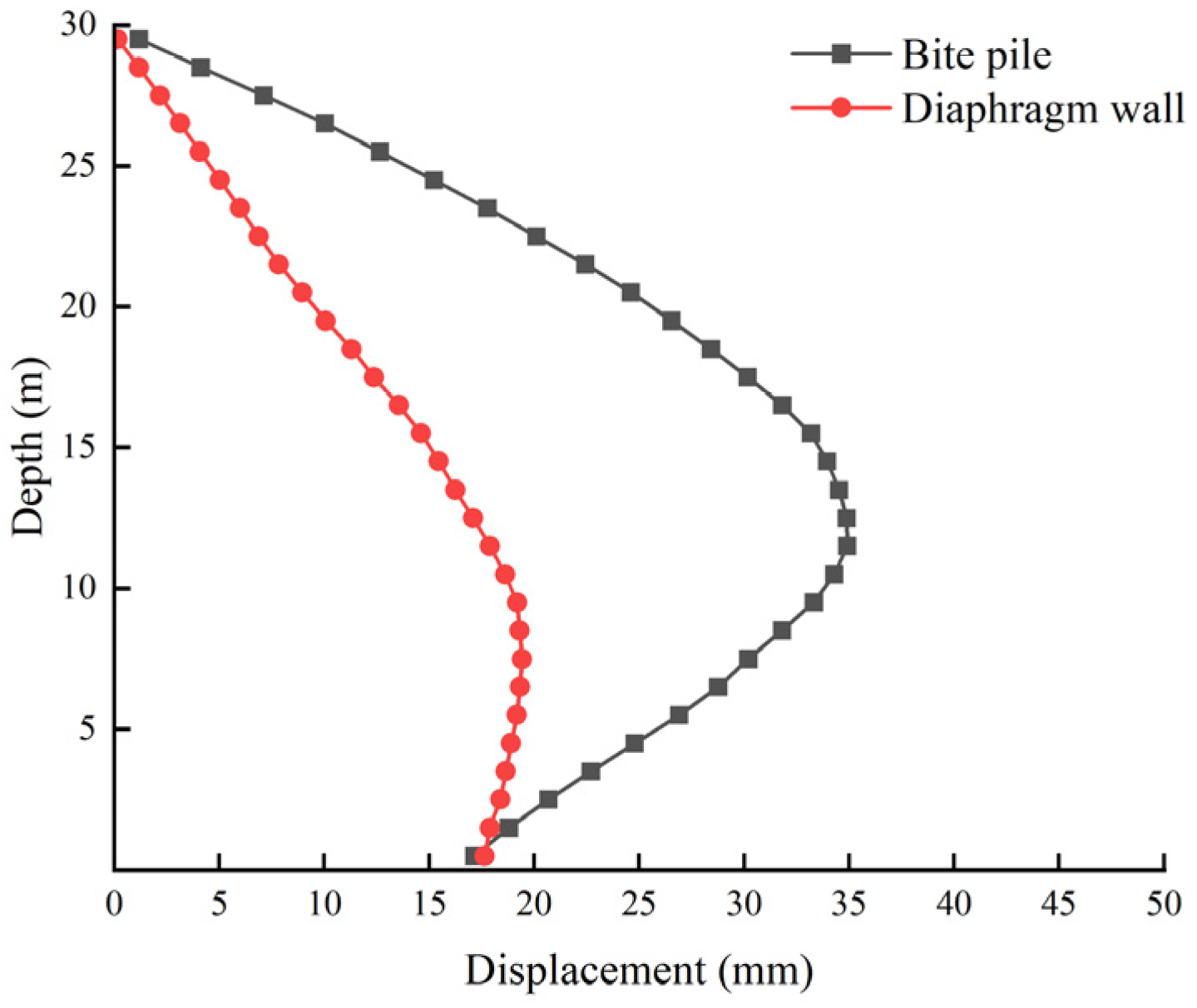
The southern side of the pit is adjacent to the Hongshuwan South Station, utilizing the existing underground contiguous wall as part of the support structure. The section with the maximum horizontal displacement from the underground continuous wall and the interlocking pile are selected, and the relationship diagram with depth as the vertical axis and horizontal displacement as the horizontal axis is drawn, as shown in Figure 5. From Figure 5, it can clearly demonstrate the advantages and disadvantages of both in limiting the displacement of foundation pits.
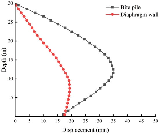
Figure 5.
Variation curve of maximum lateral displacement of support piles.
From Figure 5, both support forms exhibit an overall deformation trend towards the inner side of the pit, forming an “inward convex” appearance. The maximum lateral displacement value of the underground contiguous wall support segment is 19.42 mm (positive value indicates deformation towards the inner side of the pit), corresponding to a depth near 8 m; the maximum lateral displacement value of the bite pile support segment is 34.89 mm, corresponding to a depth near 12 m.
Analyzing the curves reveals that as the depth increases, the lateral displacement of the support structure also increases due to the increasing difference in soil pressure inside and outside the pit. However, as the pit depth approaches the bottom, the support structure experiences strong constraints from the bottom soil, resulting in reduced lateral displacement. Therefore, the maximum lateral displacement of the support structure appears near the middle depth of the pit. Additionally, due to the differences between bite piles and underground contiguous walls, there are differences in the maximum lateral displacement values and corresponding depths, with bite piles exhibiting larger lateral displacement and deeper pit depths compared to underground contiguous walls. This is mainly because underground contiguous walls are made of reinforced concrete, providing higher stiffness and stability to withstand greater horizontal loads. Furthermore, during actual pit excavation, deformation monitoring of both support structure forms should focus on the bite pile support structure to ensure that monitored values are below safety control standards.
4.2. Excavation Support Structure Internal Force Analysis
In the engineering practice of pit excavation, it is crucial not only to closely monitor the deformation of the pit but also to conduct a detailed study of the stress on the pit support structure. Among these, the bending moment and internal support axial force are two key stress parameters. During the excavation process, horizontal and vertical loads exerted by the soil lead to bending moments in the support structure. The internal support, as an essential component of the support structure, also bears significant axial forces.
According to the steps in Table 2, the foundation pit is divided into four excavations in total. In order to demonstrate more modeling details, the bending moment cloud maps of the underground continuous wall excavated four times, the bending moment cloud maps of the interlocking piles, and the axial force cloud maps of the internal supports are shown separately, as shown in Figure 6, Figure 7, Figure 8 and Figure 9.

Figure 6.
The first step after excavation and support. (a) Bending moment of underground diaphragm wall enclosure structure. (b) Bending moment of articulating pile enclosure structure. (c) Nephogram of internal support axial force after excavation.
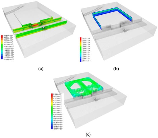
Figure 7.
The second step after excavation and support. (a) Bending moment of underground diaphragm wall enclosure structure. (b) Bending moment of articulating pile enclosure structure. (c) Nephogram of internal support axial force after excavation.
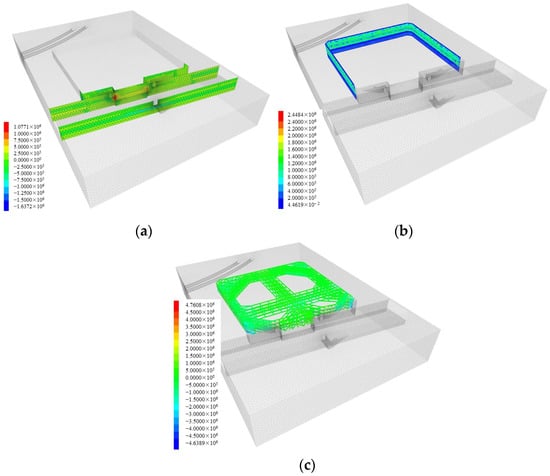
Figure 8.
The third step after excavation and support. (a) Bending moment of underground diaphragm wall enclosure structure. (b) Bending moment of articulating pile enclosure structure (c) Nephogram of internal support axial force after excavation.
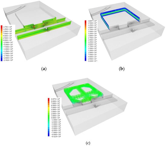
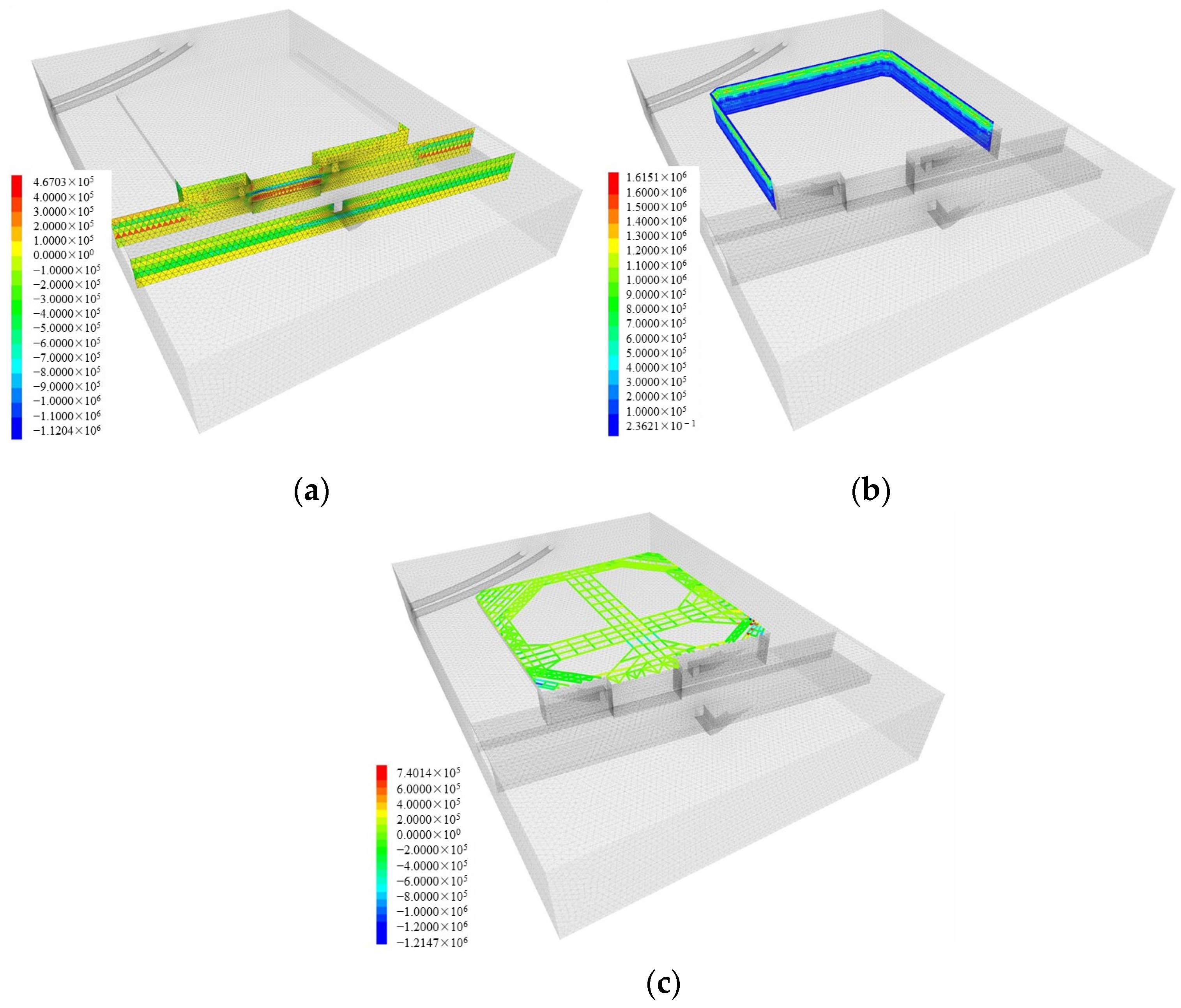
Figure 9.
The fourth step after excavation and support. (a) Bending moment of underground diaphragm wall enclosure structure. (b) Bending moment of articulating pile enclosure structure. (c) Nephogram of internal support axial force after excavation.
Figure 9 provides cloud maps of the internal forces of the support structure and internal support when the pit is excavated to the bottom. From the numerical model results, it can be observed that the maximum bending moment of the contiguous wall is 2.38 × 10⁶ N·m, located at the southwest corner of the contiguous wall, at the bottom of the pit. At the corner where the shared contiguous wall connects with the newly constructed contiguous wall, the bending moment is also significant, at 1.38 × 10⁶ N·m. The maximum bending moment of the support pile is 4.90 × 10⁶ N·m, mainly occurring around 4 m above the bottom of the pit, where the soil layer consists mainly of gravel and silty clay. The maximum axial force of the internal support is 8.42 × 10⁶ N, mainly distributed at the southeast and southwest corners of the pit.
The calculation results show that the bending moments of the support structure generally exhibit larger values in the middle part, with smaller bending moment values at the top and bottom of the pit. However, compared to the bending moments of the underground contiguous wall, the variation in bending moments is smaller, and the maximum bending moment values are significantly lower than those of the bite piles. On the other hand, the overall stress situation of the internal support is relatively balanced, with larger axial forces occurring near the junction of the bite piles and the underground contiguous wall. This is due to the noticeable differences in stiffness between the two types of support structures. To ensure continuous displacement at the junction, the internal support generates significant secondary stresses, resulting in larger axial force values of the internal support.
4.3. Tunnel and Station Structure Deformation Analysis
The subway, as an essential part of urban transportation, directly affects the safety and stability of city residents’ travel and life. Pit excavation near subway tunnels and stations often faces many technical challenges and requires special attention to reducing the impact on subway structures. In these scenarios, it is especially important to focus on reducing the impact on subway structures.
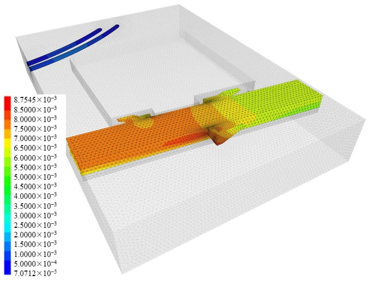
From Figure 10, it can be observed that the maximum displacement of the subway main structure after pit excavation is 8.75 mm. The predicted deformations of the subway tunnel structure are listed in Table 3 below. Since the distance between the tunnel and the pit is greater than 30 m, and there is a 0.8 m thick underground contiguous wall separating the station from the outside, the overall deformation of the station structure and tunnel lining structure caused by pit excavation is relatively small. The construction of the pit support structure follows the construction process, and the lateral displacement deformation values of the pit support structure meet the requirements of the Shenzhen Pit Support Specification.
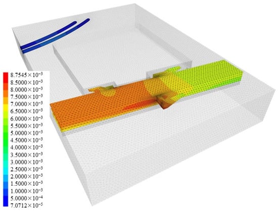
Figure 10.
Displacement nephogram of the main structure of the subway after the excavation.
Table 3.
Structural displacement of subway.
4.4. Surface Settlement Analysis
The large-scale unloading of soil caused by pit excavation will inevitably disturb the surrounding soil. To observe the range and degree of this disturbance, points were selected on the south side of the pit near two subway entrances and on the east and west sides, labeled as points A to D, as shown in Figure 11.
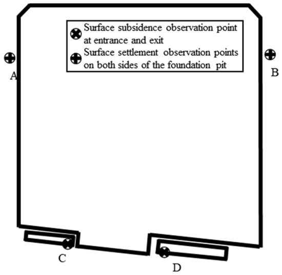
Figure 11.
Observation points of surface subsidence.
Numerical simulation results were analyzed, and the maximum uplift/settlement values at each point during the entire construction phase are listed in Table 4. Analysis of the data reveals that points A and B are near the bite pile support structure, showing an overall settlement trend during the excavation process, with similar maximum settlement degrees at both points. Points C and D are located at the C and D entrances of the Hongshuwan South Station. Due to the presence of a 0.8 m thick underground contiguous wall between the pit and the points, there is no significant settlement or uplift deformation at these points. Therefore, to ensure project safety and consider environmental protection requirements, it is advisable to select appropriate support structures based on actual conditions to achieve different soil control effects.
Table 4.
Maximum surface displacement of the observation points.
5. Numerical Simulation and Field Monitoring Comparison
5.1. Field Monitoring Layout
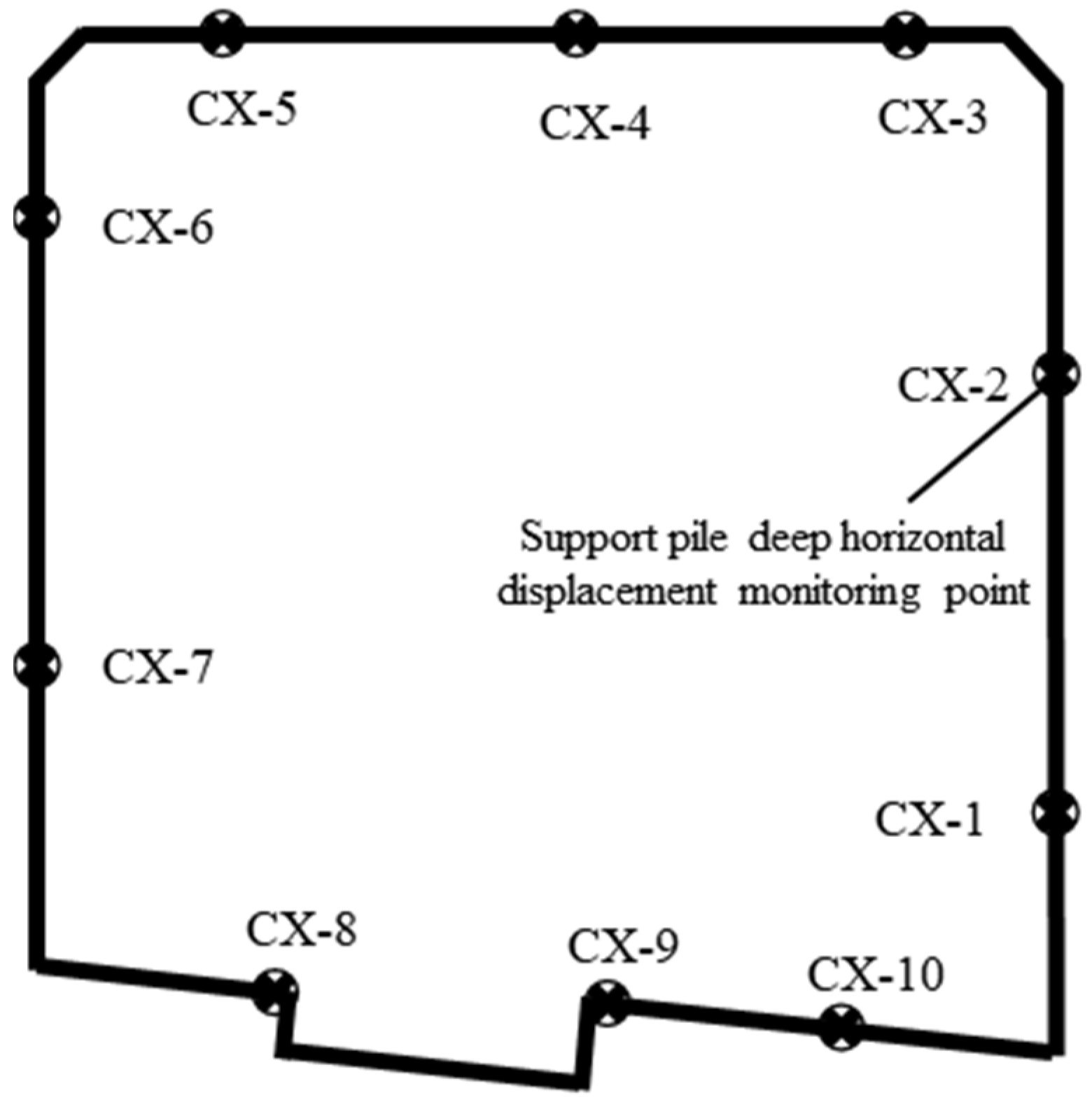
The pit construction site adopts the maintenance method of bite piles/contiguous walls combined with internal support. The existing contiguous wall of the station is used for support on the side adjacent to the existing station. To monitor the deformation of the pit and the deformation of the Hongshuwan South Station and Subway Line 2, inclinometers are installed on the support piles of the pit; manual monitoring is used for the subway station structure, with monitoring points placed on the side walls of the subway structure, with a monitoring section set every 15 m, with two monitoring points on each section monitoring horizontal and vertical displacements; automated monitoring is carried out for the subway station operation area tracks and shield tunnels. The layout of the deep horizontal displacement monitoring points for the support piles is shown in Figure 12.

Figure 12.
Monitoring points for deep horizontal displacement of support piles.
5.2. Field Monitoring vs. Numerical Simulation Results Comparison
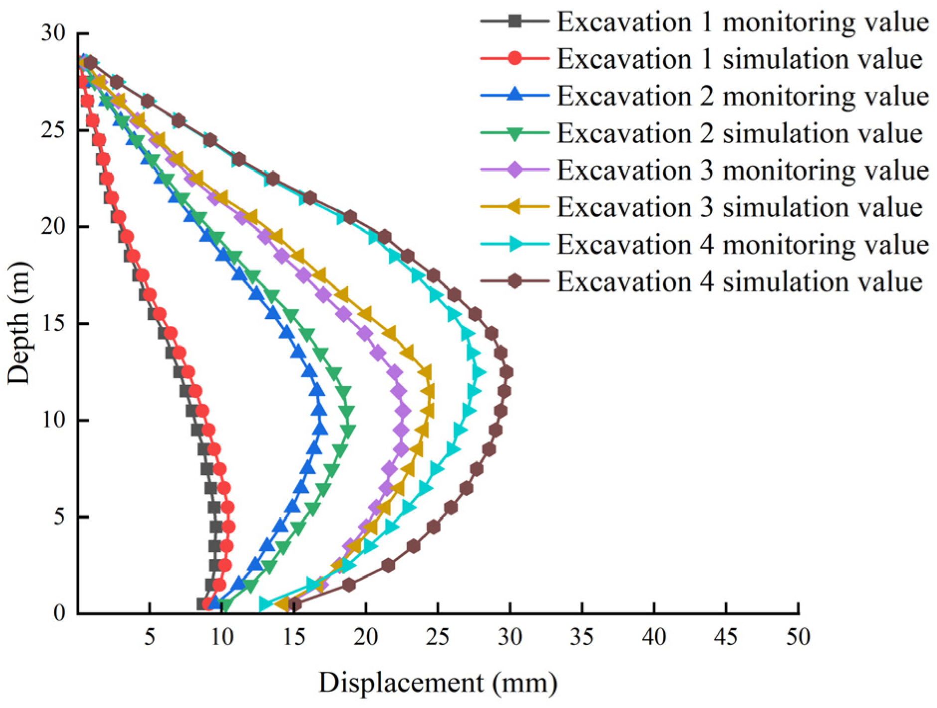
After the completion of pit excavation, to study the deformation of the pit and evaluate the pit’s risk, monitoring data of the deep horizontal displacement of support piles at position CX-5 (as shown in Figure 13) of the pit were selected, and corresponding calculation results from the numerical model were extracted to plot the horizontal displacement deformation curve, as shown in Figure 14.
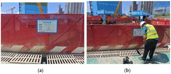
Figure 13.
(a) Pictures of CX-5 monitoring point. (b) Monitoring personnel on site.
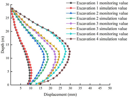
Figure 14.
Comparison between monitoring values and numerical simulation results of support piles’ displacement.
Analysis reveals that the monitored deep horizontal displacement values of the pit support piles are consistent with the numerical simulation results, with the actual displacement of the pit support piles being smaller than the numerical simulation results. During the excavation of the fourth construction phase, inclinometer values are lower than corresponding values in the third construction phase at shallower depths, likely due to the complex construction environment at the construction site of the Shenzhen Bay Super Headquarters resulting from disturbances caused by surrounding construction projects. Additionally, part of the support structure on the south side of the pit uses the existing 0.8 m thick contiguous wall of the Hongshuwan South Station as temporary support. Therefore, the horizontal displacement values at the south monitoring points of the pit are smaller, with a maximum value of 24.86 mm, while the maximum monitoring displacement values in the other three directions are 29.75 mm, 28.14 mm, and 32.57 mm, all of which are below the safety control standard during monitoring, indicating good overall stability of the pit, safety of the support structure, and low construction risk of the pit.
6. Conclusions
Based on the pit construction of the Shenzhen Bay Super Headquarters Tower C, a three-dimensional numerical model of the pit and the existing subway station and tunnel structures was established using FLAC 3D software. The deformation and internal forces of the support structure at different construction stages of the deep pit, as well as the deformation of the adjacent subway station and tunnel structures and surface settlement responses, were studied. The future direction can be to study the influence of the cross-sectional size of internal bracing beams on foundation pit support in order to determine the most economical cross-sectional size and reduce the use of materials. The main conclusions are as follows:
(1) During pit excavation, the lateral horizontal displacement of the support structure is generally small, with a typical “internal convex” deformation curve. As the pit is excavated progressively, the maximum lateral horizontal displacement increases with depth. The horizontal displacement values of the contiguous wall segment are smaller than those of the bite pile segment.
(2) The bending moments of the support structure generally exhibit larger values in the middle part, with smaller bending moment values at the top and bottom of the pit. Compared to the bending moments of the underground contiguous wall, the variation in bending moments is smaller, and the maximum bending moment values are significantly lower than those of the bite piles, with relatively uniform distribution of internal support forces.
(3) The maximum displacement near the subway station is 8.75 mm, and the maximum displacement of the subway tunnel is 2.29 mm. Under the designed support scheme, the overall deformation of the station structure and tunnel lining structure caused by pit excavation is relatively small, indicating the low construction risk of the pit.
(4) Overall, the surface exhibits a settlement trend during excavation, with the settlement amount of the contiguous wall support segment being smaller than that of the bite pile support segment. Different forms of support structures have different effects on controlling surface settlement, highlighting the importance of appropriate selection in actual engineering.
(5) The deep horizontal displacement monitoring values of the pit support piles obtained through numerical simulation are consistent with the numerical simulation results and have a certain safety margin. Designing the support system based on this can achieve the goal of safe, efficient, and economically sound construction of deep pits in actual engineering.
Author Contributions
Conceptualization, Z.J. and S.Z.; methodology, Z.J.; software, Z.J. and X.G.; validation, Z.J., S.Z., and X.Q.; writing—original draft preparation, Z.J.; writing—review and editing, S.Z. and X.Q. All authors have read and agreed to the published version of the manuscript.
Funding
This research was funded by the National Natural Science Foundation of China (Grant No. 42307192) and the Fundamental Research Funds for the Central Universities (Grant No. B240201104).
Data Availability Statement
The measured data used to support the findings of this study are included within the article.
Acknowledgments
The authors express thanks to the people who helped with this work, and acknowledge the valuable suggestions from the peer reviewers.
Conflicts of Interest
Author Zhijian Jiang was employed by the Shenzhen Water Planning & Design Institute Co., Ltd. The remaining authors declare that the research was conducted in the absence of any commercial or financial relationships that could be construed as a potential conflict of interest.
References
- Liu, B.; Zhang, D.; Wang, Y.; Wang, N.; Xu, W. Design optimization and observed performance of a super-large foundation pit excavation subjected to unsymmetrical loading in water-rich floodplain: A case study. Soils Found. 2023, 63, 101329. [Google Scholar] [CrossRef]
- Zhang, R.; Zheng, J.; Pu, H.; Zhang, L. Analysis of excavation-induced responses of loaded pile foundations considering unloading effect. Tunn. Undergr. Space Technol. 2011, 26, 320–335. [Google Scholar] [CrossRef]
- Yuan, B.; Liang, J.; Zhang, B.; Chen, W.; Huang, X.; Huang, Q.; Li, Y.; Yuan, P. Optimized reinforcement of granite residual soil via a cement and alkaline solution: A coupling effect. J. Rock Mech. Geotech. Eng. 2024, in press. [CrossRef]
- Ye, S.; Zhao, Z.; Wang, D. Deformation analysis and safety assessment of existing metro tunnels affected by excavation of a foundation pit. Undergr. Space 2021, 6, 421–431. [Google Scholar] [CrossRef]
- Yang, J.; Kong, D. Deformation of deep and large foundation pit in soft soil of Fuzhou Subway. Arab. J. Geosci. 2020, 13, 36. [Google Scholar] [CrossRef]
- Zhu, S.; Wang, H.; Zhu, Q.; Wang, Y. Experimental and numerical simulation of three-point bending fracture of brittle materials with inverted T-shaped obstacle cracks. Theor. Appl. Fract. Mech. 2023, 128, 104155. [Google Scholar] [CrossRef]
- Xiao, H.; Zhou, S.; Sun, Y. Wall deflection and ground surface settlement due to excavation width and foundation pit classi-fication. KSCE J. Civ. Eng. 2019, 23, 1537–1547. [Google Scholar] [CrossRef]
- Que, X.; Zhu, Z.; He, Y.; Niu, Z.; Huang, H. Strength and deformation characteristics of irregular columnar jointed rock mass: A combined experimental and theoretical study. J. Rock Mech. Geotech. Eng. 2023, 15, 429–441. [Google Scholar] [CrossRef]
- Luo, Z.-J.; Zhang, Y.-Y.; Wu, Y.-X. Finite element numerical simulation of three-dimensional seepage control for deep foundation pit dewatering. J. Hydrodyn. 2008, 20, 596–602. [Google Scholar] [CrossRef]
- Yin, X.; Ni, H. Displacement analysis and numerical simulation of pile-anchor retaining structure in deep foundation pit. J. Meas. Eng. 2024, 12, 124–137. [Google Scholar] [CrossRef]
- Liu, H.; Li, K.; Wang, J.; Cheng, C. Numerical simulation of deep foundation pit construction under complex site conditions. Adv. Civ. Eng. 2021, 2021, 1–11. [Google Scholar] [CrossRef]
- Yuan, C.; Hu, Z.; Zhu, Z.; Yuan, Z.; Fan, Y.; Guan, H.; Li, L. Numerical simulation of seepage and deformation in excavation of a deep foundation pit under water-rich fractured intrusive rock. Geofluids 2021, 2021, 6628882. [Google Scholar] [CrossRef]
- Lin, P.; Liu, P.; Ankit, G.; Singh, Y.J. Deformation monitoring analysis and numerical simulation in a deep foundation pit. Soil Mech. Found. Eng. 2021, 58, 56–62. [Google Scholar] [CrossRef]
- Yang, Y.; Zeng, H.; Liu, X.; Yang, B.; Li, Y. Real-Time Monitoring for Effects of Vibration and Temperature of Construction Site on Steel Assembly Bracing of Foundation Pit. Buildings 2023, 13, 450. [Google Scholar] [CrossRef]
- Wang, Z.; Wang, C. Analysis of deep foundation pit construction monitoring in a metro station in Jinan city. Geotech. Geol. Eng. 2019, 37, 813–822. [Google Scholar] [CrossRef]
- Lu, J.; Jiang, H. Numerical Simulation Study on Application of T-Shaped Composite Pile Support System in Super-Large Foundation Pit Support Engineering. Appl. Sci. 2023, 13, 11240. [Google Scholar] [CrossRef]
- Han, L.; Sun, M.; Wang, H.; Wang, G.X. Engineering Application and In-situ Monitoring Analysis of Retaining Structures of New H-section Steel Support System in Foundation Pit. E3S Web Conf. 2018, 53, 03080. [Google Scholar] [CrossRef]
- Sun, Y.; Li, Z. Study on Design and Deformation Law of Pile-Anchor Support System in Deep Foundation Pit. Sustainability 2022, 14, 12190. [Google Scholar] [CrossRef]
- Tu, B.; Zheng, J.; Ye, S.; Shen, M. Study on Excavation Response of Deep Foundation Pit Supported by SMW Piles Combined with Internal Support in Soft Soil Area. Water 2023, 15, 3430. [Google Scholar] [CrossRef]
- Yang, T.; Xiong, S.; Liu, S.; Liu, Y.; Zhao, H.; Li, Y. Numerical analysis of the influence of deep foundation pit construction on adjacent subway stations in soft soil areas. Adv. Civ. Eng. 2022, 2022, 6071868. [Google Scholar] [CrossRef]
- Niu, Y.; Wang, Q.; Ma, F. Study on the Influence of Foundation Pit Excavation on the Deformation of Adjacent Subway Tunnel in the Affected Area of Fault Zones. Sustainability 2023, 15, 9462. [Google Scholar] [CrossRef]
- Zhuang, Y.; Cui, X.; Hu, S. Numerical simulation and simplified analytical method to evaluate the displacement of adjacent tunnels caused by excavation. Tunn. Undergr. Space Technol. 2023, 132, 104879. [Google Scholar] [CrossRef]
- Yuan, B.; Chen, W.; Li, Z.; Zhao, J.; Luo, Q.; Chen, W.; Chen, T. Sustainability of the polymer SH reinforced recycled Granite Residual Soil: Properties, physicochemical mechanism, and applications. J. Soils Sediments 2023, 23, 242–262. [Google Scholar] [CrossRef]
- Zhu, S.; Zhang, Y.L.; Shao, J.F.; Zhu, Z.; Zhang, X.; Wu, J. Experimental and theoretical study on crack growth using rock-like resin samples con-taining inherent fissures and its numerical assessment. Rock Mech. Rock Eng. 2024, 57, 4815–4834. [Google Scholar] [CrossRef]
- Li, D.; Liao, F.; Wang, L.; Lin, J.; Wang, J. Multi-Stage and Multi-Parameter Influence Analysis of Deep Foundation Pit Excavation on Surrounding Environment. Buildings 2024, 14, 297. [Google Scholar] [CrossRef]
- Wang, X.; Zhu, Z.; Wang, H.; Zhu, S.; Chen, Y. Study of the crack propagation characteristics of brittle materials at low temperatures based on 3D-ILC. J. Mater. Sci. 2024, 59, 3624–3635. [Google Scholar] [CrossRef]
- Zhang, Q.; Hu, J.; Wang, J.; He, P.; Hou, L.; Lin, P.; Song, S. Study on the mechanical behavior of a foundation pit retaining structure adjacent to the pile foundation of a subway station. Environ. Earth Sci. 2021, 80, 704. [Google Scholar] [CrossRef]
- Que, X.; Zhu, Z.; Zhou, L.; Niu, Z.; Huang, H. Strength and failure characteristics of an irregular columnar jointed rock mass under polyaxial stress conditions. Rock Mech. Rock Eng. 2022, 55, 7223–7242. [Google Scholar] [CrossRef]
- Augarde, C.E.; Lee, S.J.; Loukidis, D. Numerical modelling of large deformation problems in geotechnical engineering: A state-of-the-art review. Soils Found. 2021, 61, 1718–1735. [Google Scholar] [CrossRef]


Disclaimer/Publisher’s Note: The statements, opinions and data contained in all publications are solely those of the individual author(s) and contributor(s) and not of MDPI and/or the editor(s). MDPI and/or the editor(s) disclaim responsibility for any injury to people or property resulting from any ideas, methods, instructions or products referred to in the content. |
© 2024 by the authors. Licensee MDPI, Basel, Switzerland. This article is an open access article distributed under the terms and conditions of the Creative Commons Attribution (CC BY) license (https://creativecommons.org/licenses/by/4.0/).