
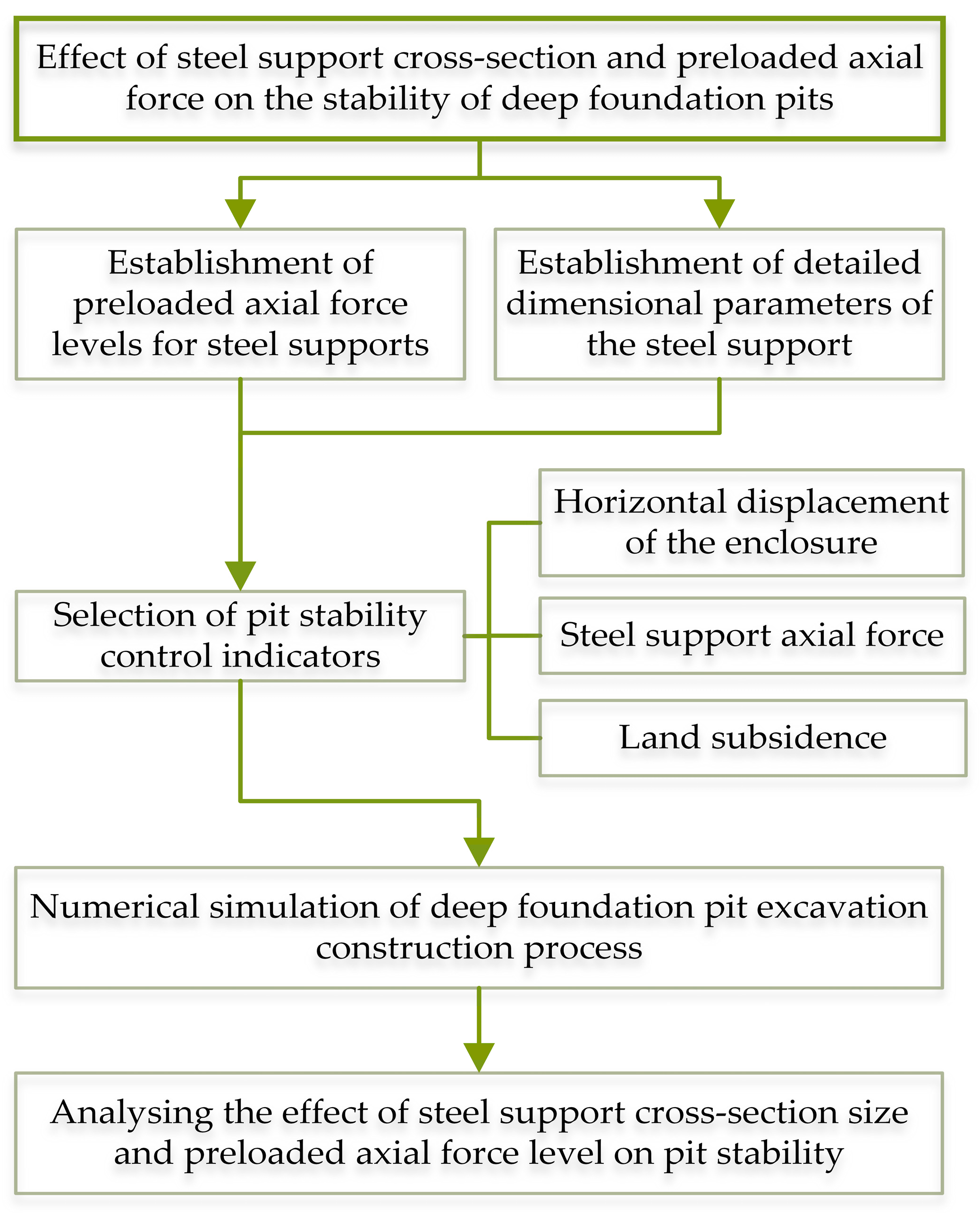
Effect of Steel Support Cross-Section and Preloaded Axial Force on the Stability of Deep Foundation Pits
Abstract
:1. Introduction
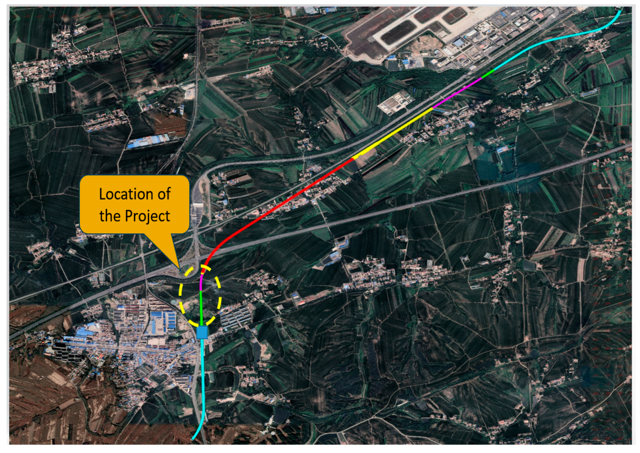
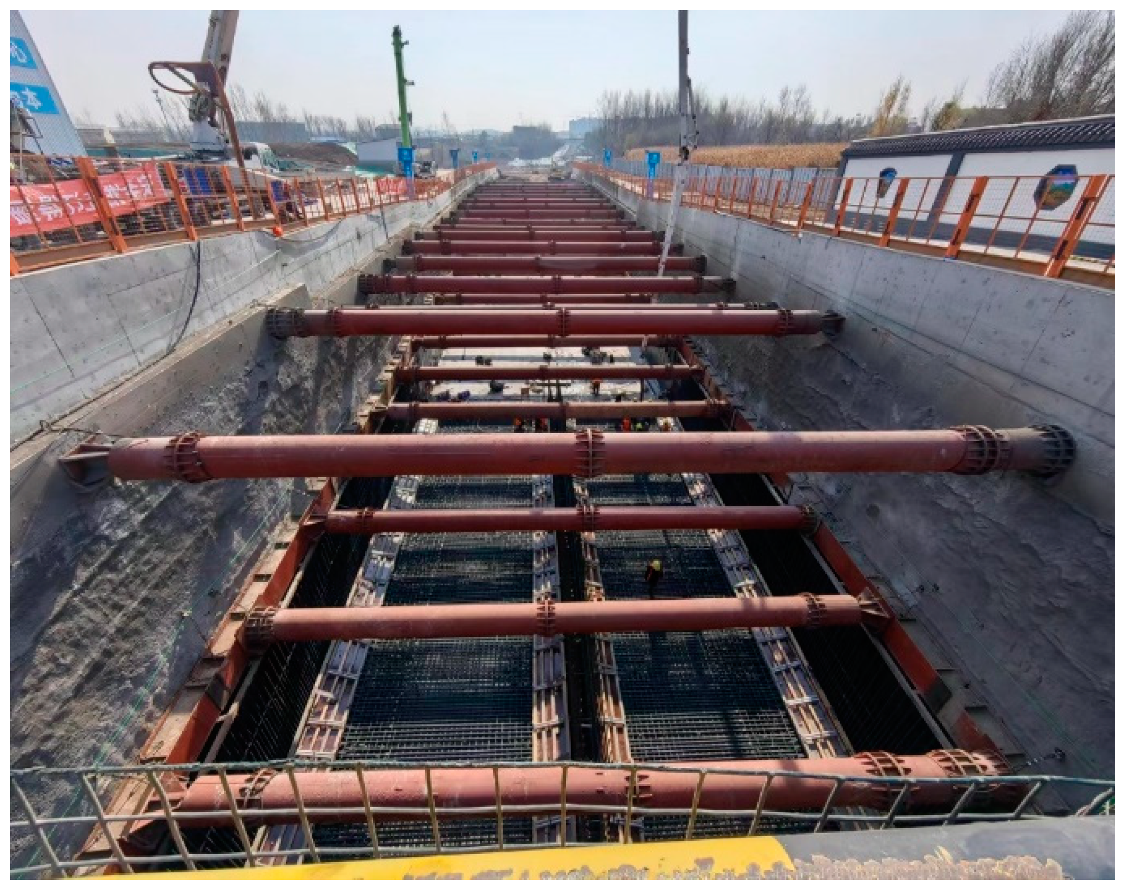
2. Project Overview
3. Numerical Simulation of Deep Foundation Pit
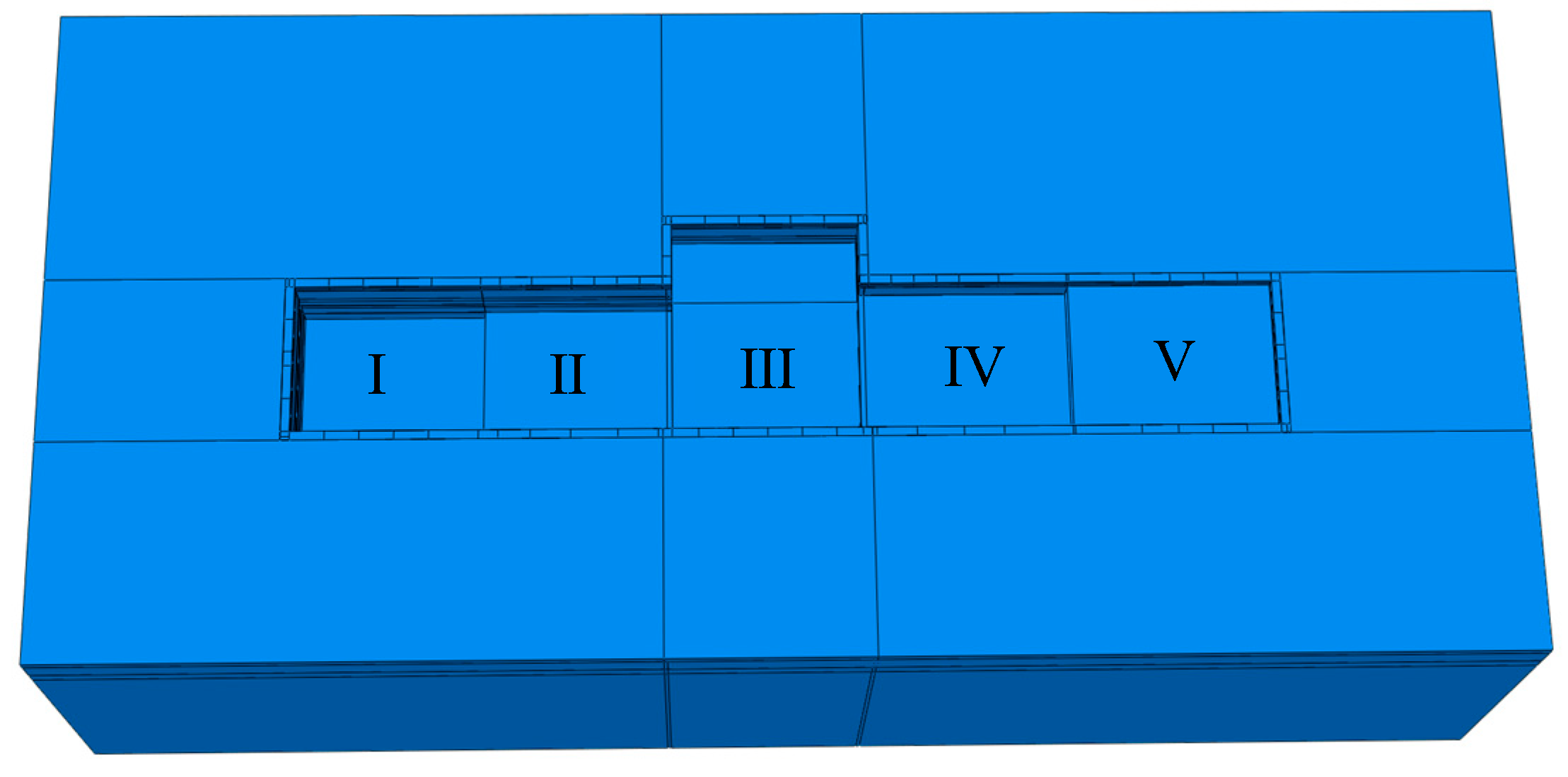
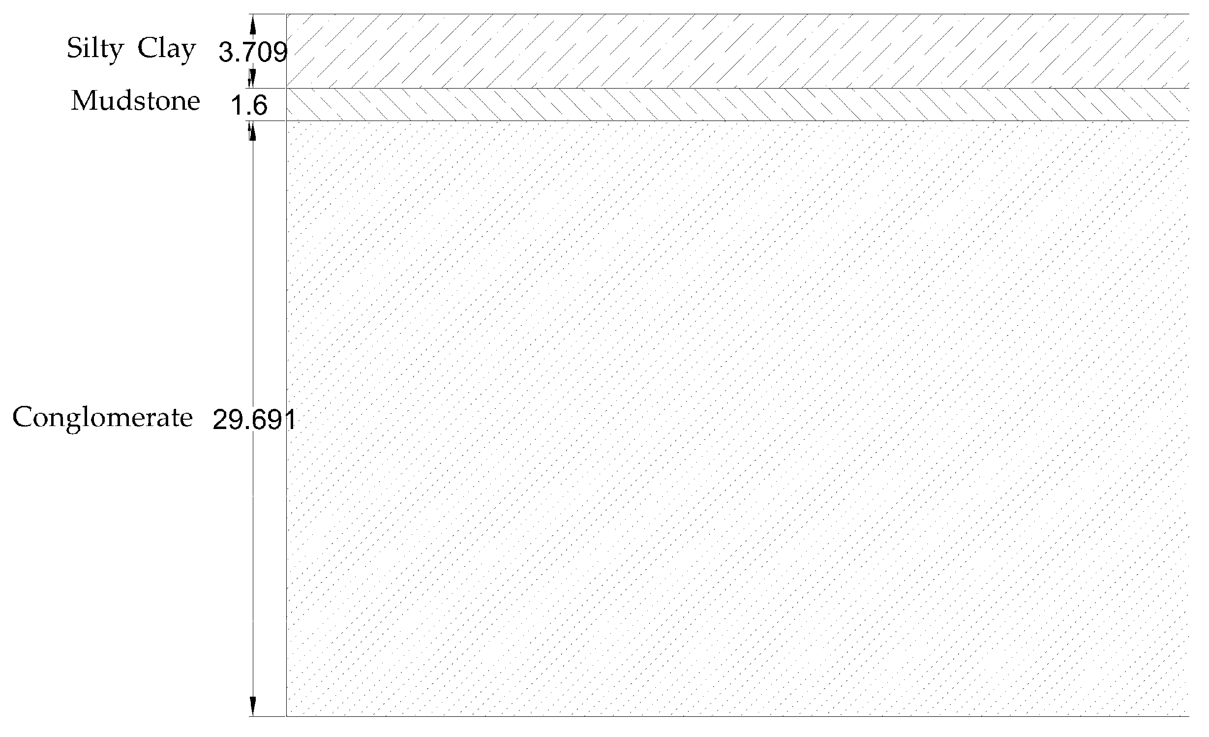
3.1. Geometric Modelling
3.2. Selection of Material Parameters
3.3. Analysis Step Establishment
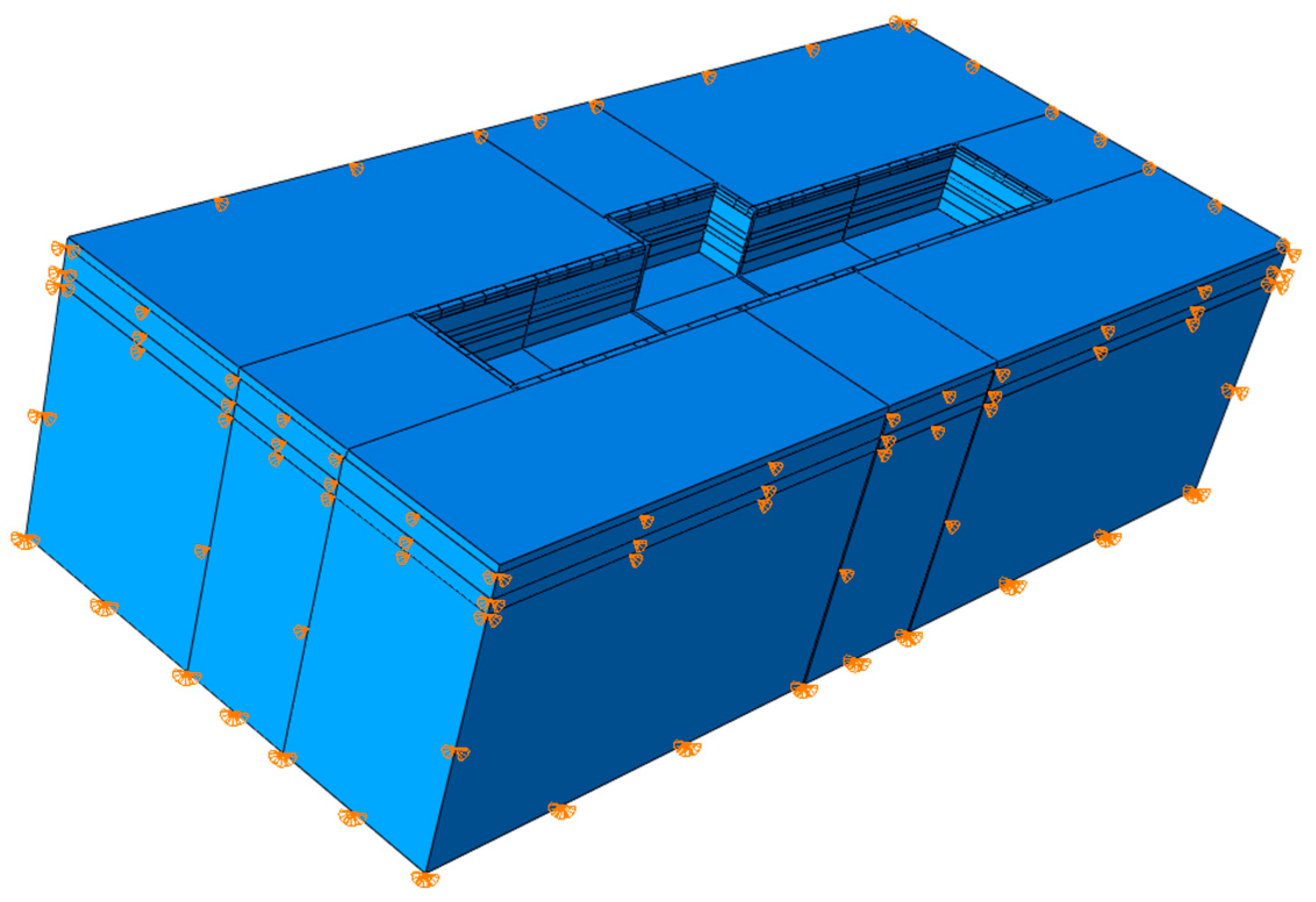
3.4. Contact and Boundary Condition Settings
3.5. Meshing
3.6. Numerical Model Validation
4. Mechanical Response Analysis of Steel Support in Deep Foundation Pit
4.1. Establishment of Evaluation Indicators
4.2. Effect of Steel Support Cross-Section Size on Pit Stability
4.2.1. Effect of Cross-Section Dimensions on Horizontal Displacements of Enclosures
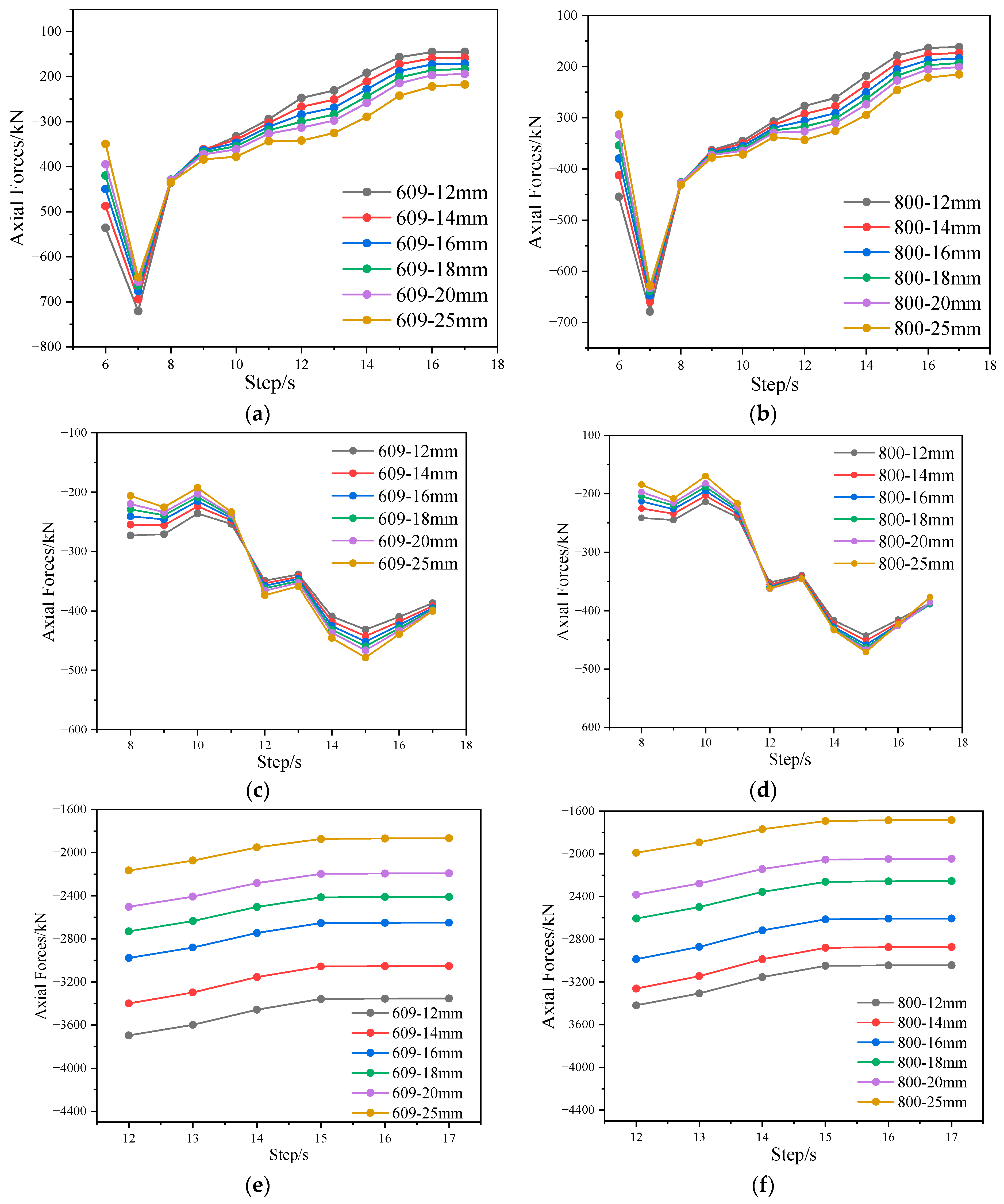
4.2.2. Effect of Steel Support Cross-Section Size on Axial Force
4.3. Effect of Preloaded Axial Force of Steel Support on the Stability of the Deep Foundation Pit
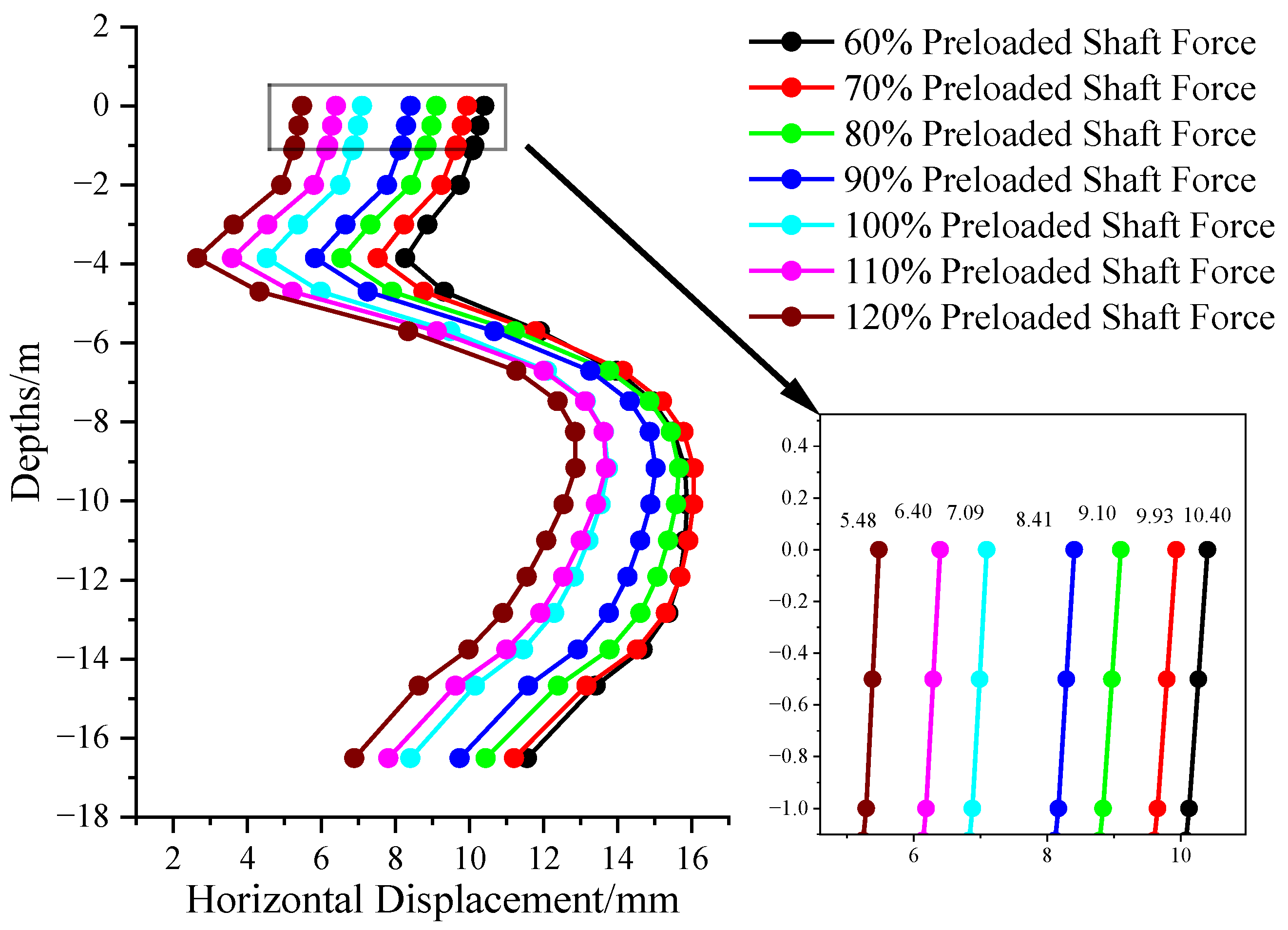
4.3.1. Effect of Preloaded Axial Force of Steel Support on Horizontal Displacement of Enclosure Structure
4.3.2. Effect of Steel Support Preloaded Axial Force on Surface Settlement
5. Discussion
- (1)
- The diameter and wall thickness of the steel support have a significant effect on both the horizontal displacement and axial force of the enclosure structure. Space constraints and material costs need to be considered comprehensively in the design.
- (2)
- During the excavation and support of the foundation pit, a real-time monitoring system should be set up to monitor key parameters such as surface settlement and axial force of steel support.
- (3)
- During the design and construction process, it is also necessary to comprehensively consider the influence of factors such as the nature of the soil, changes in the water table, and the construction process on the surface settlement. Through multi-factor analysis, a more comprehensive and scientific foundation pit support programme can be developed.
6. Conclusions
- (1)
- As an important part of the deep foundation pit structure, the detailed characteristics of the steel support will affect the safety of the foundation pit, and quantitative evaluation of the effect of the steel support diameter, wall thickness, and preloaded axial force level on the safety of the foundation pit has considerable engineering significance.
- (2)
- Under the same diameter, the horizontal displacement of the enclosing pile changes from 4.64 mm to 13.55 mm as the wall thickness increases from 14 mm to 25 mm, and the axial force of the second steel support decreases by 11.4% to 15% for every 2 mm increase in wall thickness.
- (3)
- When the diameter of the steel support changes from 609 mm to 800 mm, the axial force of the second steel support decreases by 3.2–5.5%. The analysis of the combined effect of steel support diameter and wall thickness indicate that the two have a coupling effect on the safety of the pit; the diameter of the steel support can be reduced and the wall thickness can be increased to achieve the same stabilising effect in special working conditions with space limitations.
- (4)
- Compared with a 60% preloaded axial force level, 120% preloaded axial force can reduce the horizontal displacement of the pile top in the pit by about 10 mm and that of the surface settlement by about 4.2 mm. This finding indicates that the change in the preloaded axial force of the steel support affects the horizontal displacement of the enclosure structure and the surface settlement.
- (5)
- From the perspective of pit safety, the pit can be concluded to be in a safe state when the preloaded axial force level is 60%. Thus, reducing the preloaded axial force level scientifically and reasonably is feasible under the premise of guaranteeing the safety of the pit in the actual construction process.
Author Contributions
Funding
Data Availability Statement
Conflicts of Interest
References
- Sheng, Z.; Xuan, T.K.; Jiao, Y.S.; Bing, S. Fuzzy Reliability Analysis of Resistant Heave Stability for SMW-Protected Structure Deep Foundation Pit. In Safety Science and Technology; Li, S.C., Wang, Y.J., An, Y., Sun, X.Y., Li, X., Eds.; Science Press: Beijing, China, 2008; Volume 7, pp. 2144–2148. [Google Scholar]
- Jin, Y.; Di, H.; Zhou, S.; Liu, H.; Wu, D.; Guo, H. Effects of Active Axial Force Adjustment of Struts on Support System during Pit Excavation: Experimental Study. J. Geotech. Geoenviron. Eng. 2024, 150, 04024027. [Google Scholar] [CrossRef]
- Xie, Z.; Liu, X.; Niu, X.; Jian, J.; Xu, C.; Liao, J. Study on the Influence of the Performance Weakening of the Disconnectable Coupling (DC) Joint of Steel Support on the Retaining of a Foundation Pit. Buildings 2024, 14, 1330. [Google Scholar] [CrossRef]
- Di, H.; Guo, H.; Zhou, S.; Chen, J.; Wen, L. Investigation of the Axial Force Compensation and Deformation Control of Servo Steel Struts in a Deep Foundation Pit Excavation in Soft. Adv. Civ. Eng. 2019, 2019, 5476354. [Google Scholar] [CrossRef]
- Haque, M.E. An ANN Model for Biaxial Bending of Reinforced Concrete Column. In System-Based Vision for Strategic and Creative Design; Bontempi, F., Ed.; AA Balkema Publishers: Rotterdam, The Netherlands, 2003; pp. 1517–1521. [Google Scholar]
- Muhtar. The Prediction of Stiffness Reduction Non-Linear Phase in Bamboo Concrete Beam Using the Finite Element Method (FEM) and Artificial Neural Networks (ANNs). Forests 2020, 11, 1313. [Google Scholar] [CrossRef]
- Wang, Z.; Wang, C. Analysis of Deep Foundation Pit Construction Monitoring in a Metro in Jinan City. Geotech. Geol. Eng. 2019, 37, 813–822. [Google Scholar] [CrossRef]
- Zhou, Z.; Sun, X.; Heng, C. Temperature Influence to the Steel Brace in Piles in Row-Steel Bracing. In Proceedings of the Advances in Underground Space Development, Singapore, 7–9 November 2012; Zhou, Y., Cai, J., Sterling, R., Eds.; Research Publishing Services: Singapore, 2013; pp. 1257–1264. [Google Scholar]
- He, M.D.; Zhang, D.L.; He, M.D.; Liu, J.; Le, G.P. Analysis of Supporting Structure Deformation and Axial Force in Subway Pit. In Rock Mechanics: Achievements and Ambitions; Cai, M., Ed.; CRC Press: Boca Raton, FL, USA, 2012; pp. 629–634. [Google Scholar]
- Kozlowski, M. Experimental and Numerical Assessment of Structural Behaviour of Glass Subjected to Soft Body Impact. Compos. Struct. 2019, 229, 111380. [Google Scholar] [CrossRef]
- Wang, Z.; Guo, B.; Wei, G.; Hu, C.; Zhang, L. Simplified Deformation Analyses of a Single Pile Subjected to Different Modes of the Pit Enclosure Structure. Int. J. Geomech. 2023, 23, 04023014. [Google Scholar] [CrossRef]
- Wang, Z.; Guo, B.; Wei, G.; Yao, D.; Hu, C. Study for Longitudinal Deformation of Shield Tunnel in Side of Foundation Pit Based on Virtual Image Technique. Appl. Sci. 2022, 12, 8745. [Google Scholar] [CrossRef]
- Xu, Y.; Zhao, Y.; Jiang, Q.; Sun, J.; Tian, C.; Jiang, W. Machine-Learning-Based Deformation Prediction Method for Deep-Pit Enclosure Structure. Appl. Sci. 2024, 14, 1273. [Google Scholar] [CrossRef]
- Isleem, H.F.; Chukka, N.D.K.R.; Bahrami, A.; Oyebisi, S.; Kumar, R.; Qiong, T. Nonlinear Finite Element and Analytical Modelling of Reinforced Concrete Filled Steel Tube Columns under Axial Compression Loading. Results Eng. 2023, 19, 101341. [Google Scholar] [CrossRef]
- Luo, Y.; Chen, J.; Wang, H.; Sun, P. Deformation Rule and Mechanical Characteristics of Temporary Support in Soil Tunnel Constructed by Sequential Excavation Method. Ksce J. Civ. Eng. 2017, 21, 2439–2449. [Google Scholar] [CrossRef]
- Pirmoz, A.; Danesh, F.; Farajkhah, V. The Effect of Axial Beam Force on Moment-Rotation Curve of Top and Seat Connections. Struct. Des. Tall Spec. Build. 2011, 20, 767–783. [Google Scholar] [CrossRef]
- Hsu, C.-F.; Tsai, Y.-H.; Chen, Y.-R.; Li, Y.-F.; Chen, S.-L. Normalized Analysis of Deformation for Deep Excavation Diaphragm Walls under Different Neighboring Building Conditions. Results Eng. 2024, 22, 102155. [Google Scholar] [CrossRef]
- Liu, J.; Yang, L.; Zhang, J.; Zhang, W. Stress Resultant Analysis of Steel Penstocks Using A Flat Shell Element. In Progress in Civil Engineering; Chu, M.J., Li, X.G., Lu, J.Z., Hou, X.M., Wang, X., Eds.; Elsevier: Amsterdam, The Netherlands, 2012; Volume 170–173, pp. 1887–1892. [Google Scholar]
- Han, S.; Yang, K.; Wei, X.; Yun, L.; Cheng, C. Analysis of the Influence of inside and Outside Water Level Changes of foundation Pit on Stability of Foundation. In Proceedings of the 2nd International Conference on Architectural, Civil and Hydraulics Engineering (ICACHE 2016), Kunming, China, 29–30 September 2016; pp. 280–284. [Google Scholar]
- Zhang, Y.; Wang, Y.; Zhao, Y. A Case Study on the Deformation of Metro Foundation Pit in Silt Stratum in North China. Shock. Vib. 2021, 2021. [Google Scholar] [CrossRef]
- Cheng, X.; He, J.; Li, X.; Xia, Q.; Su, H.; Chen, C. Deformation rule of bored pile & steel support for deep foundation pit in sandy pebble geology. Civ. Eng. J.-Staveb. Obz. 2023, 33, 282–297. [Google Scholar] [CrossRef]
- Wang, Q.; Ma, P.; Shi, Z. Study on Influence of Vertical Position of Steel Bracing in Foundation of Open Cut Railway on Deformation of Envelope Structure. IOP Conf. Ser. Earth Environ. Sci. 2020, 455, 012128. [Google Scholar] [CrossRef]
- James, A.; Kurian, B. Diaphragm Wall Retaining System—A Simplified Model for Design Loads. Aust. J. Civ. Eng. 2022, 20, 374–388. [Google Scholar] [CrossRef]
- Hua, J.; Zheng, J. Geological Engineering Handbook; China Architecture & Building Press: Beijing, China, 2018. [Google Scholar]
- DB22-T5020-2019; Technical Standard for Monitoring Measurementof Urban Rail Transit ENGINEERING. Jilin Provincial Department of Housing and Urban-Rural Development: Changchun, China, 2019.


| Soil Layer | Density/(kg/m3) | Internal Friction Angle/° | Cohesive Force/kPa | Poisson’s Ratio | Elastic Modulus/MPa |
|---|---|---|---|---|---|
| Silty Clay | 2000 | 20 | 33 | 0.25 | 39 |
| Mudstone | 2500 | 25 | 50 | 0.25 | 6000 |
| Conglomerate | 2140 | 28 | 40 | 0.25 | 11,000 |
| Materials | Density/(kg/m3) | Elastic Modulus/MPa | Poisson’s Ratio |
|---|---|---|---|
| C30 Concrete | 2450 | 30,000 | 0.3 |
| Q235B Steel | 7850 | 210,000 | 0.3 |
| Step | Analysis Step Content | Step | Analysis Step Content |
|---|---|---|---|
| 1 | Ground Stress Equilibrium | 10 | Erection of The Second Steel Support for Section II and The First Steel Support for Section IV. |
| 2 | Enclosure Construction | 11 | I Section V, II Section IV, III Section III, IV Section II, V Section I Soil Excavation |
| 3 | Excavation of The First Layer of Soil in Section I | 12 | Erection of The Second Steel Support for Section III and The First Steel Support for Section V. |
| 4 | Erection of The First Steel Support for Section I | 13 | II Section V, III Section IV, IV Section III, V Section II Soil Excavation |
| 5 | Excavation of The Second Layer of Section I and The First Layer of Section II | 14 | Erection of The Second Steel Support for Section IV |
| 6 | Erection of The First Steel Support for Section II | 15 | Excavation of The Soil in Layer 5 of Section III, Layer 4 of Section IV, Layer 3 of Section V |
| 7 | Excavation of Soil in Layer 3 of Section I, Layer 2 of Section II, Layer 1 of Section III | 16 | Excavation of Soil in Layer 5 of Section IV and Layer 4 of Section V |
| 8 | Erection of The First Steel Support for Section III | 17 | Excavation of Soil Layer 5 of Section V |
| 9 | Excavation of Soil in Layer 4 of Section I, Layer 3 of Section II, Layer 2 of Section III, Layer 1 of Section IV |
| Monitoring Projects | Engineering Monitoring Level II | ||
|---|---|---|---|
| Cumulative Value/mm | Rate of Change/(mm/d) | ||
| Absolute Value | Relative Pit Depth (H) Value | ||
| Vertical Displacement of Pile Top | 20–30 | 0.15–0.3% | 3–4 |
| Horizontal Displacement of Pile Top | 20–30 | 0.15–0.3% | 3–4 |
| Horizontal Displacement of Pile Body | 30–40 | 0.2–0.4% | 3–4 |
| Surface Settlement | 25–35 | 0.2–0.3% | 2–4 |
| Rebounding of Pit Bottom Elevation | 25–35 | 2–3 | |
| Supporting Axial Force | Maximum Value: (70–80%) f Minimum Value: (80–100%) fy | ||
| Depths/m | Diameter 609 mm Steel Support Wall Thickness/mm | |||||
|---|---|---|---|---|---|---|
| 12 mm | 14 mm | 16 mm | 18 mm | 20 mm | 25 mm | |
| 0 | 9.27 | 8.03 | 7.09 | 6.55 | 5.73 | 4.64 |
| 0.50 | 7.93 | 6.94 | 6.17 | 5.76 | 5.08 | 4.20 |
| 1.00 | 6.60 | 5.84 | 5.26 | 4.96 | 4.42 | 3.75 |
| 1.13 | 6.23 | 5.51 | 4.96 | 4.68 | 4.18 | 3.55 |
| 2.00 | 3.88 | 3.43 | 3.09 | 2.92 | 2.60 | 2.22 |
| 3.00 | 6.18 | 5.26 | 4.56 | 4.13 | 3.55 | 2.75 |
| 3.85 | 9.43 | 8.03 | 6.94 | 6.29 | 5.39 | 4.16 |
| 4.70 | 1.49 | 1.20 | 0.98 | 0.84 | 0.68 | 0.44 |
| 5.70 | −7.04 | −6.14 | −5.44 | −4.54 | −3.97 | −2.87 |
| 6.70 | −11.67 | −10.21 | −9.06 | −7.58 | −6.65 | −4.83 |
| 7.47 | −13.46 | −11.83 | −10.55 | −8.85 | −7.80 | −5.72 |
| 8.24 | −14.57 | −12.86 | −11.51 | −9.70 | −8.58 | −6.34 |
| 9.20 | −15.46 | −13.71 | −12.33 | −10.43 | −9.26 | −6.90 |
| 10.15 | −15.91 | −14.17 | −12.78 | −10.85 | −9.66 | −7.24 |
| 11.11 | −16.08 | −14.36 | −12.99 | −11.06 | −9.87 | −7.44 |
| 12.07 | −15.90 | −14.24 | −12.92 | −11.02 | −9.85 | −7.46 |
| 12.95 | −15.25 | −13.69 | −12.44 | −10.63 | −9.52 | −7.23 |
| 13.84 | −13.69 | −12.31 | −11.21 | −9.59 | −8.60 | −6.54 |
| 14.73 | −10.67 | −9.60 | −8.75 | −7.49 | −6.72 | −5.12 |
| 15.62 | −6.65 | −5.99 | −5.46 | −4.67 | −4.19 | −3.20 |
| 16.50 | −5.42 | −4.88 | −4.44 | −3.80 | −3.41 | −2.59 |
| Depths/m | Diameter 800 mm Steel Support Wall Thickness/mm | |||||
|---|---|---|---|---|---|---|
| 12 mm | 14 mm | 16 mm | 18 mm | 20 mm | 25 mm | |
| 0 | 8.57 | 7.42 | 6.38 | 5.42 | 4.52 | 3.54 |
| 0.50 | 7.52 | 6.59 | 5.73 | 4.91 | 4.14 | 3.32 |
| 1.00 | 6.47 | 5.75 | 5.06 | 4.40 | 3.75 | 3.09 |
| 1.13 | 6.12 | 5.44 | 4.79 | 4.16 | 3.55 | 2.92 |
| 2.00 | 3.85 | 3.42 | 3.01 | 2.62 | 2.23 | 1.84 |
| 3.00 | 5.60 | 4.73 | 3.97 | 3.29 | 2.68 | 1.99 |
| 3.85 | 8.51 | 7.18 | 6.01 | 4.97 | 4.04 | 2.99 |
| 4.702 | 1.22 | 0.95 | 0.73 | 0.56 | 0.41 | 0.24 |
| 5.70 | −6.66 | −5.79 | −4.98 | −3.81 | −3.19 | −2.23 |
| 6.70 | −11.10 | −9.68 | −8.37 | −6.42 | −5.38 | −3.80 |
| 7.47 | −12.91 | −11.32 | −9.84 | −7.59 | −6.38 | −4.55 |
| 8.24 | −14.09 | −12.42 | −10.83 | −8.39 | −7.09 | −5.09 |
| 9.20 | −15.08 | −13.36 | −11.72 | −9.12 | −7.73 | −5.60 |
| 10.15 | −15.63 | −13.91 | −12.25 | −9.56 | −8.14 | −5.94 |
| 11.11 | −15.88 | −14.18 | −12.53 | −9.81 | −8.37 | −6.13 |
| 12.07 | −15.78 | −14.13 | −12.51 | −9.82 | −8.39 | −6.18 |
| 12.95 | −15.18 | −13.63 | −12.09 | −9.50 | −8.13 | −6.00 |
| 13.84 | −13.67 | −12.29 | −10.91 | −8.59 | −7.36 | −5.44 |
| 14.73 | −10.67 | −9.60 | −8.54 | −6.72 | −5.76 | −4.27 |
| 15.62 | −6.65 | −5.99 | −5.32 | −4.19 | −3.59 | −2.66 |
| 16.50 | −5.42 | −4.87 | −4.32 | −3.40 | −2.91 | −2.15 |
Disclaimer/Publisher’s Note: The statements, opinions and data contained in all publications are solely those of the individual author(s) and contributor(s) and not of MDPI and/or the editor(s). MDPI and/or the editor(s) disclaim responsibility for any injury to people or property resulting from any ideas, methods, instructions or products referred to in the content. |
© 2024 by the authors. Licensee MDPI, Basel, Switzerland. This article is an open access article distributed under the terms and conditions of the Creative Commons Attribution (CC BY) license (https://creativecommons.org/licenses/by/4.0/).
Share and Cite
Jin, Y.; Zhao, H.; Zheng, C.; Liu, J.; Ding, C. Effect of Steel Support Cross-Section and Preloaded Axial Force on the Stability of Deep Foundation Pits. Buildings 2024, 14, 2532. https://doi.org/10.3390/buildings14082532
Jin Y, Zhao H, Zheng C, Liu J, Ding C. Effect of Steel Support Cross-Section and Preloaded Axial Force on the Stability of Deep Foundation Pits. Buildings. 2024; 14(8):2532. https://doi.org/10.3390/buildings14082532
Chicago/Turabian StyleJin, Yang, Hanzhe Zhao, Chuanfeng Zheng, Jian Liu, and Chong Ding. 2024. "Effect of Steel Support Cross-Section and Preloaded Axial Force on the Stability of Deep Foundation Pits" Buildings 14, no. 8: 2532. https://doi.org/10.3390/buildings14082532