Article

Study on the Diffusion Law of Grouting Slurry at the Pile Tip of Bored Piles in Gravel Pebble Layers

1
Construction and Engineering School, Jinhua Polytechnic, Jinhua 321000, China
2
China Power Construction Group East China Survey and Design Research Institute Co., Ltd., Hangzhou 311100, China
3
Construction and Engineering School, Zhejiang University, Hangzhou 310027, China
*
Author to whom correspondence should be addressed.
Buildings 2024, 14(8), 2555; https://doi.org/10.3390/buildings14082555
Submission received: 15 June 2024 / Revised: 6 August 2024 / Accepted: 11 August 2024 / Published: 19 August 2024
(This article belongs to the Section Building Energy, Physics, Environment, and Systems)

Abstract

:
The post-construction improvement technology of bored pile tips has been widely used in the construction of gravel pebble layers, but the diffusion law of the grouting slurry remains to be revealed. To study the diffusion law of the grouting slurry at the tip of bored piles in gravel pebble layers, an equivalent relationship between the seepage continuity equation and the mass diffusion continuity equation was established based on an in-depth comparative analysis; further relying on the Diluted Species Transport Module in Porous Media of Comsol Multiphysics, a three-dimensional numerical model of slurry diffusion was established to systematically study the impact of key factors such as different porosities, grouting times, grouting pressures, slurry diffusion coefficients, and the ratio of vertical to horizontal slurry diffusion coefficients on the diffusion radius of the slurry. The calculation results show that with the continuation of grouting, the increase in porosity, grouting pressure, and slurry diffusion coefficient, or the decrease in the ratio of vertical to horizontal slurry diffusion coefficients, the diffusion range of the slurry increases accordingly. Furthermore, comparatively speaking, the impact of porosity is the smallest, while the impact of the slurry diffusion coefficient is the greatest. The research findings reflect the diffusion trend of the slurry in the gravel pebble layer, which has guiding significance for the quality control of the actual design and construction of grouting.

1. Introduction

China has many mountains and rivers, and the geological conditions are complex. In areas with more mountains and rivers, sandstone and gravel soils are widely developed, and the geological conditions are relatively good. To reach or cross the gravel layer, bored piles are commonly used as the foundation for urban buildings. However, the soil cover layer of the foundation is relatively shallow and mostly consists of moderately to slightly weathered rock layers, with the sediment from bored piles mainly being gravel. To eliminate the adverse effects of the sediment at the bottom of the hole, the engineering community often uses the post-grouting improvement technology at the bottom of the bored piles. This technology involves grouting to allow the slurry to seep into the smallest gaps of the pile end sediment, combining with the sediment to form a cement coagulation block. The cement slurry further seeps into the bearing layer at the pile end, forming an enlarged head that continuously increases with the progress of grouting. Obviously, it has a compaction effect on the bearing layer at the pile end, increasing the bearing area at the pile end, thereby enhancing the bearing capacity of the bored piles.
The post-grouting improvement technology at the pile end has been proven effective in enhancing the bearing capacity of pile foundations since its first use in the construction of the Maracaibo Bridge in 1958 [1]. It is understandable that the enhancement of the bearing capacity of bored piles is closely related to the diffusion law of the post-grouting slurry, and many domestic and foreign scholars have conducted numerous studies on this; for example, Sun Bintang et al. [2] established the basic differential equation of seepage for post-grouting slurry at the pile end; a series of existing experimental tests by Bezuijen [3], Talmon [4], and Ding [5] have shown that the slurry has rheological characteristics as a Bingham fluid and grouting diffusion during the grouting process; Yang Xiuzhu et al. [6] derived a formula for calculating the effective diffusion radius of Bingham fluid slurry during permeation grouting in sandy soil; Liu Jian et al. [7] systematically studied the diffusion law of cement slurry in planar fractures under static and dynamic water conditions through model testing and numerical simulation; He Jianlong et al. [8] used the FLAC3D program to simulate the range of cement slurry diffusion at the pile end; Lin Yuanjun et al. [9] conducted numerical simulation research on the seepage field and displacement field of soft rock roadways, analyzing the impact of grouting pressure, rock permeability, and slurry viscosity on reinforcement effects; Huang Yaoguang et al. [10,11] established models of slurry diffusion under different grouting pressures, grouting times, and anchor spacing to study the seepage and diffusion laws of full-section anchor grouting slurry in tunnel surrounding rocks. Zhang Jian et al. [12] developed a formula for calculating the diameter and the climb height of the cement core of jet grouting (CCJG). It must be acknowledged that the aforementioned research has to some extent revealed the diffusion law of post-grouting slurry at the pile end, but due to the great diversity of engineering geological conditions, theoretical analysis and experimental simulation are also difficult to universalize, and there is currently a lack of systematic research on the factors affecting the diffusion law of post-grouting slurry in gravel layers and their sensitivity [13,14,15,16,17,18,19,20].
Therefore, this paper establishes a three-dimensional numerical model of post-grouting slurry diffusion at the pile end of bored piles in gravel layers based on the finite element software Comsol Multiphysics(Version 6.1.0.357). Based on the seepage continuity equation and the material diffusion equation, sensitivity analysis is conducted on the influence of grouting time, porosity, grouting pressure, slurry diffusion coefficient, and the ratio of vertical to horizontal slurry diffusion coefficients on the diffusion radius and rebound height of the slurry, revealing the diffusion law of post-grouting slurry at the pile end of bored piles in gravel layers. The conclusions have guiding significance for the design and construction of post-grouting at the pile end of bored piles in gravel layers.

2. Model Establishment

2.1. The Slurry Diffusion Model Based on the Continuity Equation of Seepage

To study the impact of various factors on the diffusion effect of the slurry, the following assumptions are made here: (1) the soil mass is continuous, homogeneous, and isotropic; (2) the porosity and permeability coefficient of the soil mass are constant values and do not change during the grouting process; (3) the slurry is a homogeneous, incompressible Newtonian fluid. At this point, the diffusion process of the slurry in the soil can be regarded as the seepage process of groundwater in the soil, which satisfies the continuity equation of unsteady seepage motion [21]:
ρ v x x + ρ v y y + ρ v z z = S s p t
S s = ρ g a + n β
In the equation: ρ represents the slurry density (kg/m3); v x , v y , v z represents the tensor of the seepage velocity of the slurry in each direction (m/s); S s represents the storage coefficient (dimensionless); p represents the grouting pressure (kPa); α represents the soil compression coefficient(dimensionless); n represents the porosity(dimensionless); β represents the slurry compressibility coefficient(dimensionless).
According to Darcy’s Law, since the soil mass is isotropic, the seepage velocity is related to the slurry pressure by the following relationship:
v x = K γ p x v y = K γ p y v z = K γ p z
In the equation: K is the slurry diffusion coefficient, and γ is the slurry unit weight (kN/m3).
By combining Equations (1) to (3), we can obtain:
2 p x 2 + 2 p y 2 + 2 p z 2 = S s K p t
We use the Comsol Multiphysics module for dilute species transport in porous media to simulate the diffusion process of the slurry in the soil. Assuming that no chemical reactions occur between the slurry and the soil during the transport process, and that the velocity in the soil’s flow field is zero, the governing equation for the material diffusion module of this module is:
D 2 c x 2 + 2 c y 2 + 2 c z 2 = n c t
In the equation: D is the diffusion coefficient of the substance(dimensionless), n is the porosity of the porous medium(dimensionless), and c is the concentration of the substance (mol/m3).
Comparing Equations (4) and (5), and setting:
D = n K S s
c = p γ
Obviously, an equivalent relationship can be established between Equations (1) and (5), therefore, this module can be used to simulate the diffusion pattern of the slurry.

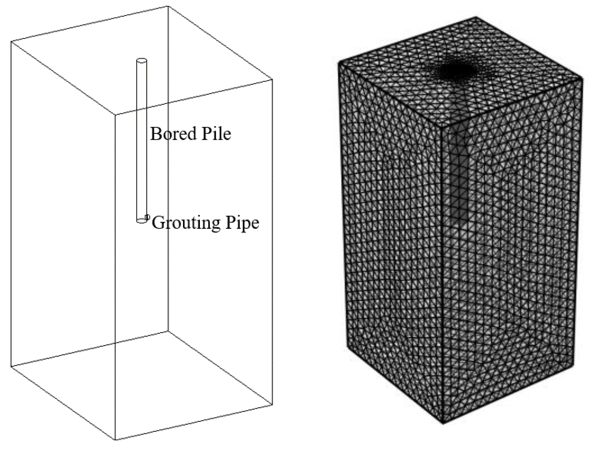
2.2. Model Establishment Process

The study utilizes the Diluted Species Transport Module for porous media to conduct the research. The model is configured as a 20 × 20 × 40 (m) cube, with the bored pile located at the center of the model. The pile has a diameter of 1 m and a length of 20 m, and grouting pipes with an inner diameter of 5.0 cm are placed on both sides at the bottom of the pile. Figure 1 illustrates the computational model and its mesh division.
Simultaneously, based on the actual conditions of post-grouting at the pile tip, it is assumed that the slurry is injected from the bottom of the grouting pipe and diffuses towards the surrounding area and bottom of the soil. The lower surface of the grouting pipe is set as the initial grouting pressure surface boundary, with the surrounding and bottom surfaces of the cube defined as outflow surface boundaries, and the remaining surfaces as no-flow surfaces. The four sides and bottom of the cube are defined as “outflow” boundaries, simulating the diffusion path of the slurry in the soil. The diffusion path of the slurry in the soil should be from the grouting pipe mouth into the soil, and under the action of gravity and grouting pressure, it flows towards the bottom and surrounding areas. It is worth noting that although there is a certain upward reflow of the slurry during the grouting process, this is due to the infiltration speed of the slurry lagging behind the grouting speed and does not mean that the upper surface is also an outflow boundary.
Furthermore, based on the case analysis of bored pile projects in the gravel pebble layer and a review of relevant specifications, the empirical values of porosity, grouting time, slurry diffusion coefficient, and grouting pressure as shown in Table 1 [22,23,24,25,26,27] are selected to study the impact of these parameters on the diffusion pattern of the slurry.
Figure 2 illustrates the schematic diagram of slurry diffusion for a specific working condition obtained using Comsol, along with its corresponding front view and top view.

3. Numerical Simulation

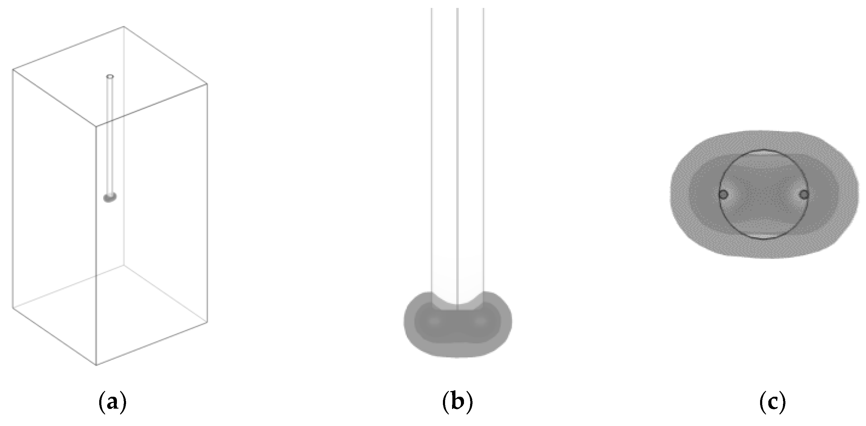
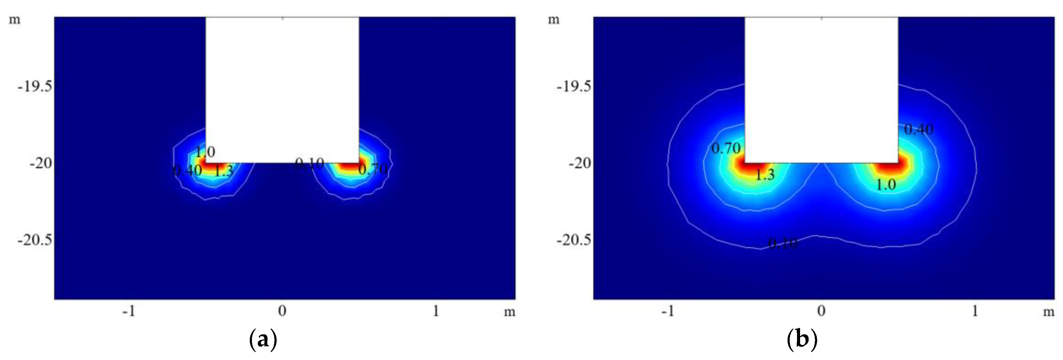
3.1. Slurry Diffusion Pattern Analysis

The study of the slurry diffusion pattern takes time as the independent variable and the slurry diffusion radius as the dependent variable to explore the extent of the impact of various factors. According to the previous context, the calculation time is selected from 0 to 300 s with a time step of 10 s. After calculation and processing, the change in the slurry diffusion range over time and the contour cloud map of the slurry diffusion range can be obtained.
Assuming initial grouting conditions with a porosity of 0.3, a slurry diffusion coefficient of 3 × 10⁻⁴ m/s, and a grouting pressure of 2 MPa, the effect of different factors on slurry diffusion is studied by changing the value of a certain factor. Figure 3 shows the contour cloud map of the slurry diffusion radius changing with grouting time under given influencing factors. Since the soil mass is assumed to be isotropic, the diffusion pattern of the slurry is symmetrically distributed in all directions. By selecting a vertical section passing through the center of the pile as the object of observation, it can be seen that the slurry diffusion on both sides first forms a smaller enlarged head near the grouting mouth on both sides of the pile end. As time goes on, the slurry diffusion radius increases, and the slurry on both sides begins to converge and wrap up the entire bottom of the pile.

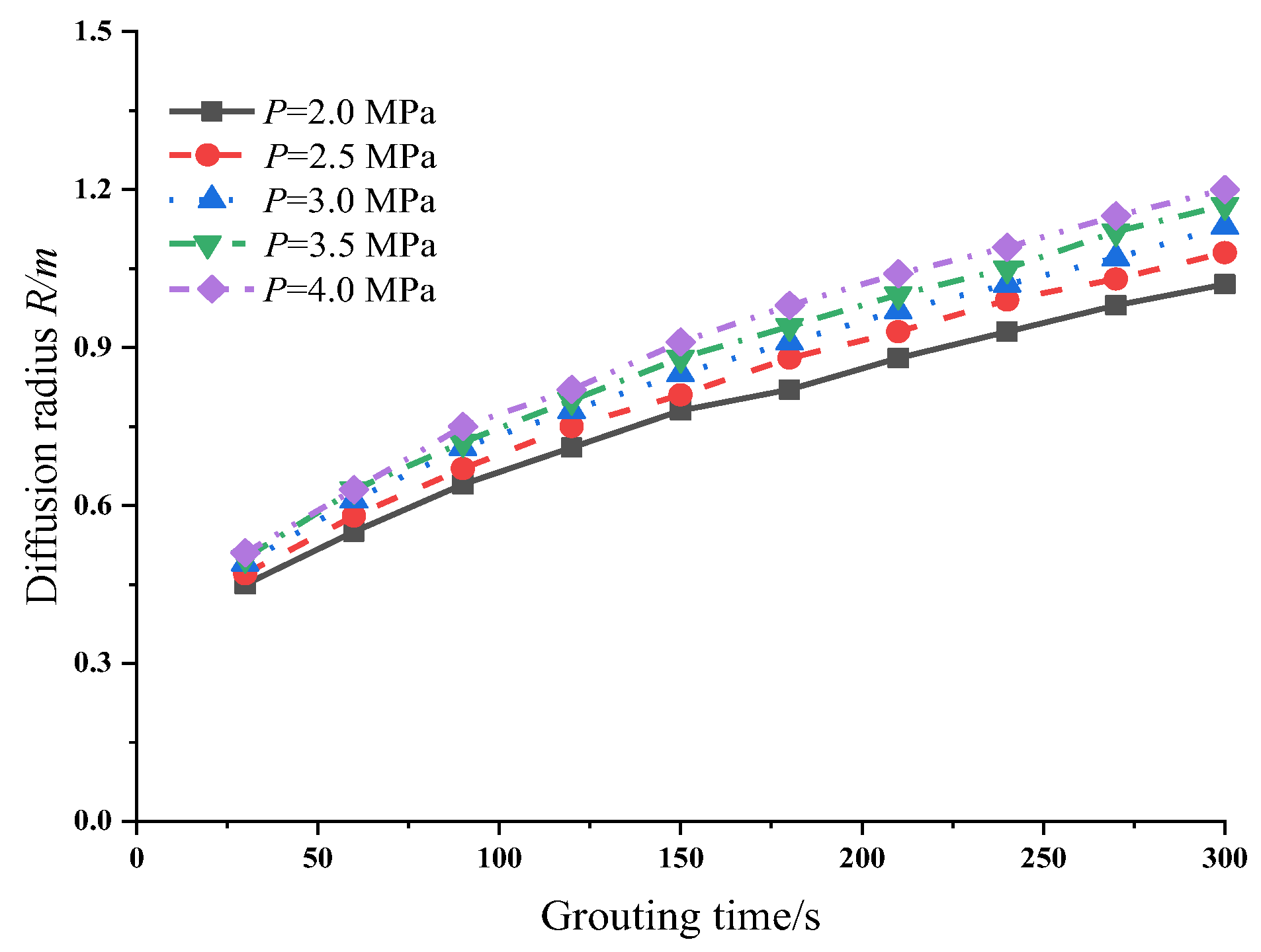
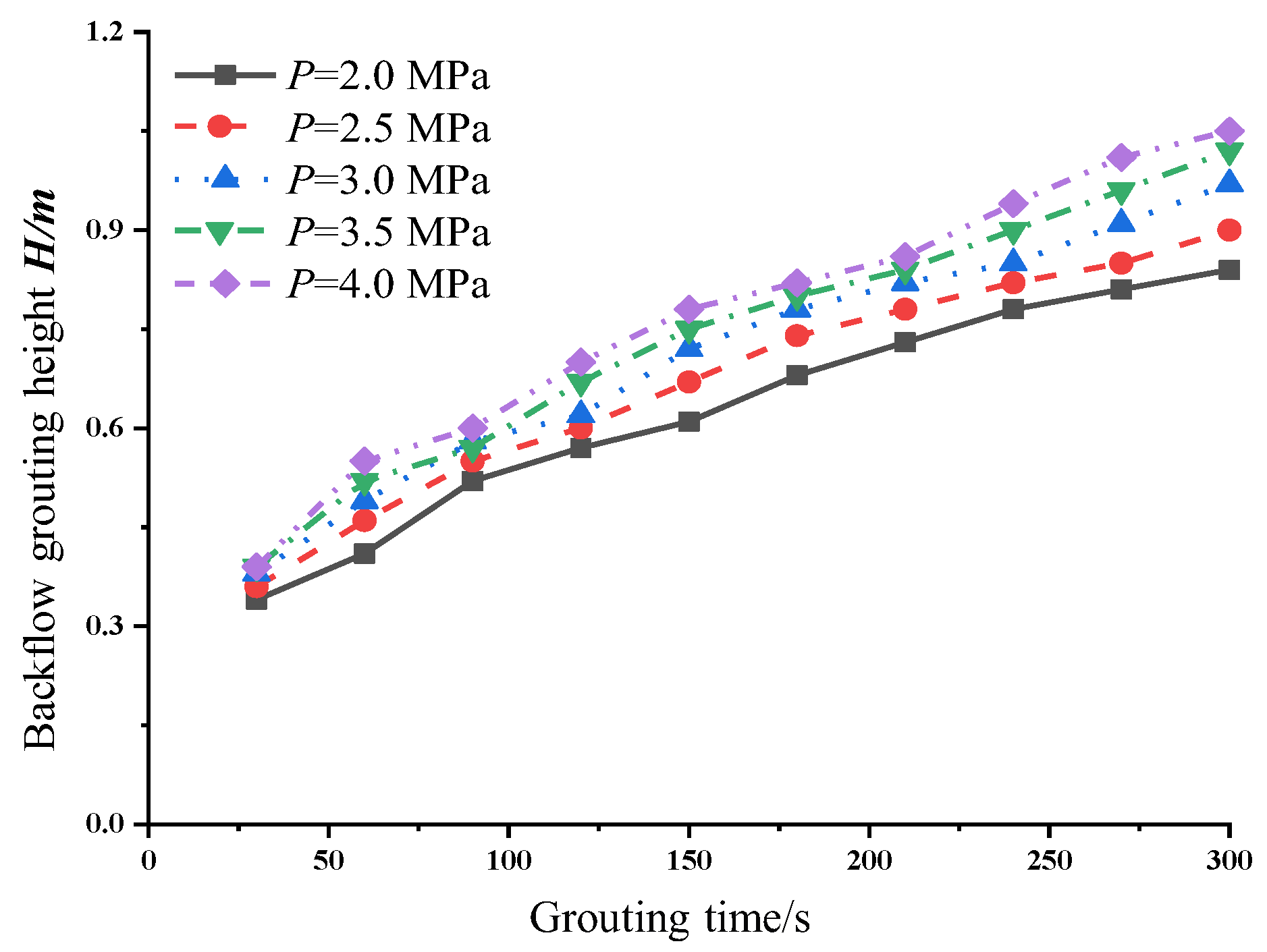
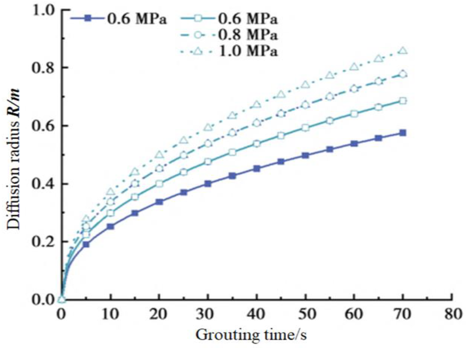
3.2. The Influence of Grouting Pressure

To study the impact of grouting pressure on the diffusion range of the slurry, the relationship between the diffusion radius of the slurry, the rebound height, and time was investigated under the condition that the initial grouting conditions remain unchanged, with a variation in grouting pressure from 2 MPa to 4 MPa. Figure 4 and Figure 5, respectively, show the change curves of the slurry diffusion radius and rebound height under different pressures as a function of grouting time.
From Figure 4 and Figure 5, it can be observed that both the diffusion range of the slurry and the rebound height increase with the increase in grouting pressure. When the grouting time is 300 s and the grouting pressure is increased from 2 MPa to 4 MPa, the slurry diffusion radius and rebound height increase by 17.6% and 25.0%, respectively. Clearly, this is due to the increased grouting pressure, which enlarges the pressure difference between the grouted and ungrouted zones. According to Darcy’s Law, the flow velocity of the slurry in the soil also increases, resulting in a larger diffusion range for the same grouting time. In summary, increasing the grouting pressure not only expands the radius of slurry penetration but also significantly raises the rebound height. Therefore, in practical engineering, one can consider increasing the grouting pressure to expand the diffusion range of the slurry, but it is also necessary to select an appropriate grouting pressure to control the rebound height.
To verify the rationality of the calculation model, the model’s computational results are compared with the research findings of Liu Jun et al. [28]. Figure 4 and Figure 6 demonstrate the relationship between the diffusion radius and grouting pressure in the gravel layer. Although the grouting pressures differ, the underlying pattern is similar, allowing the two to corroborate each other, and it is clear that there is a positive correlation between the diffusion radius and the grouting pressure.

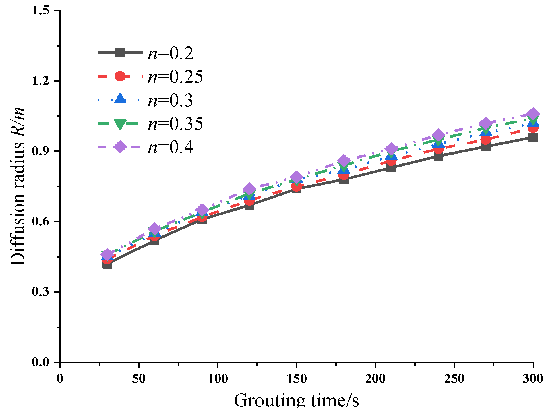
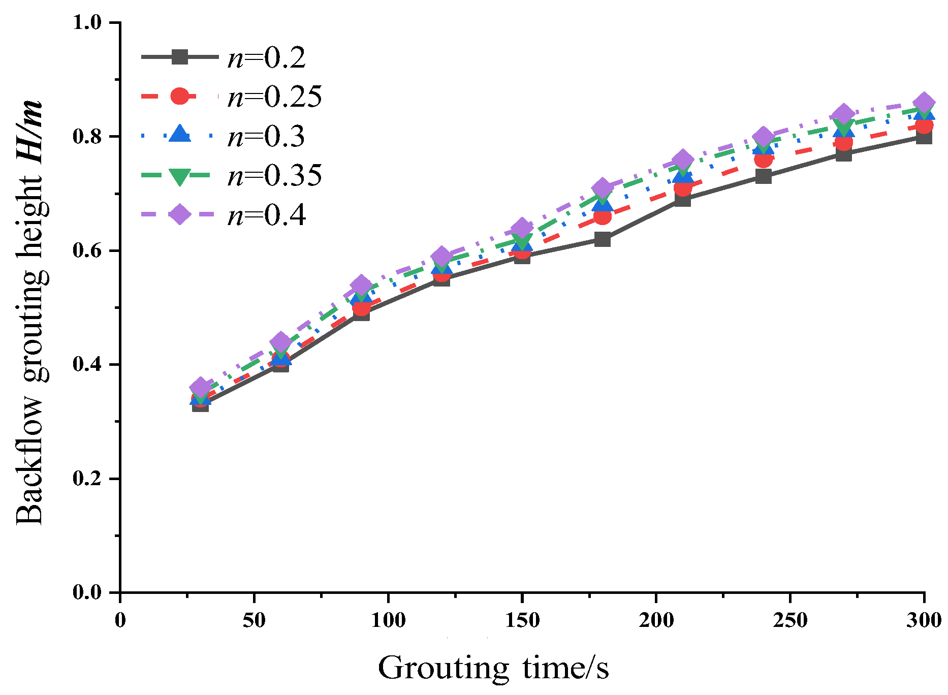
3.3. The Influence of the Porosity of the Gravel Layer at the Pile Tip

Furthermore, to study the impact of porosity on the diffusion range of the slurry, the porosity of the gravel layer at the pile tip was varied, with calculations performed for porosities of 0.2, 0.25, 0.3, 0.35, and 0.4. Figure 7 and Figure 8 present the variation curves of the slurry diffusion radius and the rebound height at different porosities over the grouting time.
From Figure 7 and Figure 8, it can be seen that the increase in the porosity of the gravel layer at the pile tip has no significant effect on the grout diffusion radius and the grout return height. In the early stage of grouting, the grout diffusion is insufficient, and there is no significant difference in the grout diffusion radius and grout return height between different porosities. When the grouting time reaches 300 s and the porosity increases from 0.2 to 0.4, the grout diffusion radius and grout return height only increase by 10.4% and 7.5%, respectively. It can be seen that the influence of the porosity of the gravel layer at the pile tip on grout diffusion is not simply a matter of promotion or inhibition, but the result of the interplay of various factors, which should be considered comprehensively. On the one hand, it is assumed that the soil at the pile tip is homogeneous and isotropic, and according to Darcy’s law, the lower the porosity, the faster the grout passes through the soil pores under the same grouting pressure, thus the faster the grout diffusion. Based on this, an increase in porosity is not conducive to grout diffusion. On the other hand, as can be seen from Equation (6), the grout diffusion coefficient is positively correlated with the porosity, and an increase in porosity is beneficial to grout diffusion. It can be seen that only by considering the above situations can we correctly analyze the impact of porosity on the grout diffusion pattern.
Although the increase in the pile tip porosity does not have a significant effect on grout diffusion, and porosity is difficult to change through actual engineering measures, this result also indicates that the post-grouting reinforcement technology at the pile tip is universally applicable to gravel layers with different porosities and is a feasible method.
To verify the rationality of the calculation model, the model’s computational results are compared with the research findings of Liu Jun et al. [28]. Figure 7 and Figure 9 reveal the relationship between the diffusion radius and the porosity of the pebble layer. Moreover, when the grouting time is 70 s and the porosity is 0.4, the diffusion radii corresponding to both figures are around 0.6 m, which verifies the rationality of the calculation model presented in this paper.

3.4. The Influence of the Slurry Diffusion Coefficient and Its Anisotropy

Based on the initial grouting conditions, the study investigated the relationship between the slurry diffusion radius, rebound height, and grouting time with the variation of the slurry diffusion coefficient ranging from 3 × 10⁻⁴ m/s to 6 × 10⁻⁴ m/s. The computational results are shown in Figure 8 and Figure 9.
Figure 10 and Figure 11 indicate that the slurry diffusion coefficient has a significant impact on the diffusion radius of the slurry. As can be seen from the figures, when the grouting time is 300 s and the slurry diffusion coefficient is 6 × 10⁻⁴ m/s, the slurry diffusion radius reaches 1.36 m, which is a 33.3% increase compared to the case where the slurry diffusion coefficient is 3 × 10⁻⁴ m/s. This is because the slurry diffusion coefficient directly affects the mobility of the slurry in the soil; the larger the slurry diffusion coefficient, the stronger the diffusion capability, and the greater the diffusion range of the slurry in the soil. Since the permeability coefficient of the slurry is related to the viscosity of the slurry, the increase in the slurry diffusion coefficient can be achieved by altering the water–cement ratio of the slurry. Therefore, to facilitate construction and ensure quality, the water–cement ratio should be between 0.5 and 0.7.
Furthermore, to study the impact of the ratio of vertical to horizontal slurry diffusion coefficients (KV:KH) on the diffusion of the slurry, calculations were performed with different KV:KH ratios of 1:1, 1:5, 1:10, 1:20, and 1:50.
Figure 12 indicates that as the KV:KH ratio decreases, the slurry diffusion radius increases. When the grouting time is 300 s, compared to the scenario with a KV:KH of 1:1, the diffusion radius of the slurry increases by 4.9%, 8.8%, 10.8%, and 12.7% for KV:KH ratios of 1:5, 1:10, 1:20, and 1:50, respectively. It can be observed that the increase in the slurry diffusion radius is not significant as the KV to KH ratio decreases.
Figure 13 shows the rebound height changing with grouting time under different KV:KH conditions. The figure demonstrates that when the grouting time is 300 s, the rebound height significantly decreases when the KV:KH ratio changes from 1:1 to 1:5, reducing from 0.84 m to 0.4 m. However, when the KV:KH ratio is 1:10, 1:20, and 1:50, the change in rebound height between these levels is minimal, indicating that altering the KV:KH ratio has a limited effect on reducing the rebound height at this point. Considering the impact of various factors on the rebound height, the computational results suggest that the sensitivity to the KV:KH ratio is the highest. This is because the permeability coefficient of the slurry in the soil is related to the properties of the soil, and in engineering practice, the horizontal permeability coefficient of the slurry in the soil is generally greater than the vertical permeability coefficient.

4. Conclusions

This paper, on the basis of comparing and analyzing the continuity equation of seepage flow and the continuity equation of material diffusion, has identified the equivalence between the two; relying on the porous medium dilute substance transfer module of Comsol Multiphysics, a three-dimensional numerical model of grout diffusion in the post-boring grouting of bored piles at the pile tip in a cobble layer has been established, and a systematic study has been conducted on the impact of key factors such as different porosities, grouting time, grouting pressure, grout permeability coefficient, and the ratio of vertical to horizontal grout permeability coefficients on the diffusion radius of the grout. The conclusions are as follows:
(1)
The diffusion process of the grouting slurry at the pile tip in the soil is regarded as the seepage process of water in the soil. By comparing the continuity equation of seepage and the continuity equation of substance diffusion, an equivalent relationship between the two is established. A 3D numerical model for slurry diffusion is established using the Diluted Species Transport Module for porous media in Comsol Multiphysics, and the contour cloud map of the slurry diffusion trend is obtained;
(2)
In the early stage of grouting, since the diffusion of the slurry is not sufficient, the impact of various influencing factors on the slurry diffusion radius is relatively small. As the grouting time extends, the impact of these factors on the slurry diffusion radius becomes increasingly significant;
(3)
With the continuation of grouting, the increase in pile-end porosity, grouting pressure, and slurry diffusion coefficient, or the decrease in the ratio of vertical to horizontal slurry diffusion coefficients, leads to an expansion of the slurry diffusion range. Among these, the pile-end porosity has the least impact on the slurry diffusion range, while the slurry diffusion coefficient has the greatest impact. To facilitate construction and ensure quality, the water–cement ratio should be between 0.5 and 0.7;
(4)
In practical engineering, the rebound height can be controlled, and the quality of grouting and reinforcement effect can be improved by adjusting the grouting pressure and changing the water–cement ratio of the slurry.

Author Contributions

Conceptualization and Editing, J.L.; data curation, Y.W. and C.W.; methodology, F.Z. and Q.Z.; formal analysis, G.Z., Z.Y. and R.X. All authors have read and agreed to the published version of the manuscript.

Funding

This research was funded by the Science and Technology Program of the Ministry of Housing and Urban-Rural Development (2020-K-149), Zhejiang Provincial Department of Education Scientific Research Project (Y201941554), Jinhua City Science and Technology Plan Project (2023-4-047).

Institutional Review Board Statement

Not applicable.

Informed Consent Statement

Not applicable.

Data Availability Statement

Data are contained within the article.

Acknowledgments

The authors gratefully acknowledge all the reviewers who participated in the review.

Conflicts of Interest

Authors Gangping Zhang and Zihai Yan were employed by the company China Power Construction Group East China Survey and Design Research Institute Co., Ltd. The remaining authors declare that the research was conducted in the absence of any commercial or financial relationships that could be construed as a potential conflict of interest.

References

  1. Shi, P. Special Technical Problems in Deep Foundation Engineering; China Communications Press: Beijing, China, 2004; pp. 35–48. [Google Scholar]
  2. Sun, B.T.; Ling, X.Z.; Ling, C.; Zhu, G.R. Numerical simulation for diffusion and pressure distribution of permeation grouting. J. Hydraul. Eng. 2007, 38, 1402–1407. [Google Scholar]
  3. Bezuijen, A.; Talmon, A.; Kaalberg, F.; Plugge, R. Field measurements of grout pressures during tunneling of the Sophia rail tunnel. Soils Found. 2004, 44, 39–48. [Google Scholar] [CrossRef]
  4. Talmon, A.M.; Huisman, M. Fall velocity of particles in shear flow of drilling fluids. Tunn. Undergr. Space Technol. Inc. Trenchless Technol. Res. 2005, 20, 193–201. [Google Scholar] [CrossRef]
  5. Ding, W.; Duan, C.; Zhu, Y.; Zhao, T.; Huang, D.; Li, P. The behaviour of synchronous grouting in a quasi-rectangular shield tunnel based on a large visualized model test. Tunn. Undergr. Space Technol. 2019, 83, 409–424. [Google Scholar] [CrossRef]
  6. Yang, X.Z.; Wang, X.H.; Lei, J.S. Study on grouting diffusion radius of Bingham fluids. J. Hydraul. Eng. 2004, 6, 75–79. [Google Scholar]
  7. Liu, J.; Liu, R.T.; Zhang, X.; Li, S.C. Diffusion law model test and numerical simulation of cement fracture grouting. Chin. J. Rock Mech. Eng. 2012, 31, 2445–2452. [Google Scholar]
  8. He, J.; Chao, S. Diffusion simulation and calculation of post-grouted bored piles. Struct. Eng. 2013, 29, 136–140. [Google Scholar]
  9. Lin, Y.; Han, L. Numerical simulation of grouting diffusion and loosening ring reinforcement in soft rock roadway. Coal Technol. 2020, 39, 16–19. [Google Scholar]
  10. Huang, Y.; Wang, L.; Lu, Y. Study on the law of slurry diffusion within roadway surrounding rock during the whole section bolt-grouting process. J. Min. Saf. Eng. 2015, 32, 240–246. [Google Scholar]
  11. Huang, Y. Seepage and Diffusion Mechanisms of Blot-Grouting Slurry within Fractured Surrounding Rocks of Deep Roadway; China University of Mining and Technology: Beijing, China, 2015. [Google Scholar]
  12. Zhang, J.; Xu, Y.; Wu, D.; Liu, C.; Cheng, G.; Gao, Q.; Ren, Z.; Guo, C. Study on the Diffusion Parameters of Newtonian Fluid in High-Pressure Jet Disturbance Grouting. Buildings 2024, 14, 1491. [Google Scholar] [CrossRef]
  13. Qian, Z.; Jiang, Z.; Cao, L. Research and application of penetration radius calculation method for permeation grouting. Ind. Constr. 2012, 42, 100–104. [Google Scholar] [CrossRef]
  14. Khoshzaher, E.; Khodaei, S.; Chakeri, H. Laboratory investigation of the effect of sodium silicate and bentonite on the mechanical properties of the grout behind the segment in mechanized excavation. Rud.-Geološko-Naft. Zb. 2024, 39, 63–74. [Google Scholar] [CrossRef]
  15. Viviescas, J.C. Probabilistic Analyses of a Post-Grouted Anchor–Soil Bond Friction Performance Considering the Geological Origin and the SPT-N Tendency with Depth. Int. J. Geomech. 2023, 23, 06022038. [Google Scholar] [CrossRef]
  16. Useche-Infante, D.J.; Aiassa-Martinez, G.M.; Arrua, P.A.; Eberhardt, M. Performance evaluation of post-grouted drilled shafts: A review. Innov. Infrastruct. Solut. 2022, 7, 1–23. [Google Scholar] [CrossRef]
  17. Mavoungou, D.N.; Zhang, P.; Zhang, S.; Wang, Q. Numerical Simulation Research on Response Characteristics of Grouting Defects of Ground Penetrating Radar for Detection of Grouting Quality behind Tunnel Wall. J. World Archit. 2021, 5, 1–20. [Google Scholar] [CrossRef]
  18. Barbosa, M.G.T.; de Assis, A.P.; da Cunha, R.P. An Innovative Post Grouting Technique for Soil Nails. Geotech. Geol. Eng. 2022, 40, 5539–5546. [Google Scholar] [CrossRef]
  19. Nabizadeh, C.J. The performance of grouted and un-grouted helical piles in sand. Int. J. Geotech. Eng. 2019, 13, 516–524. [Google Scholar] [CrossRef]
  20. Zhong, Z.; Li, J.; Bie, C. Theoretical Approach to Predicting the Diffusion Radius of Fracture Grouting in Soil–Rock Mixtures. Appl. Sci. 2023, 13, 4730. [Google Scholar] [CrossRef]
  21. Xue, Y.; Wu, J. Ground Water Dynamics; Geological Publishing House: Beijing, China, 2010; pp. 29–31. [Google Scholar]
  22. Zhu, Y.; Li, F.; Yang, X.; MA, X.; Yin, L. Monitoring and numerical simulation analysis of red sandtone foundation pit excavation of Lanzhou subway. J. Lanzhou Univ. Technol. 2022, 48, 121–127. [Google Scholar]
  23. Li, D.; Gao, X.; Ma, J.; Lei, J. Relationship between Permeability Coefficient and Effective Grain Size of Sand-Pebble Strata in Luoyang Area. J. Henan Univ. Sci. Technol. (Nat. Sci.) 2021, 42, 65–69+75+8. [Google Scholar]
  24. Li, S.; Luo, A.; Liu, G.; Luo, J. Discussion on grouting bottom-sealing water-repellent treatment and parameter optimization for foundation pit of water rich pebble stratum. West. China Commun. Sci. Technol. 2019, 4, 7–9+62. [Google Scholar] [CrossRef]
  25. Zhang, S.; He, S.; Zhu, Z.; Li, C. Research on soil conditioning for earth pressure balance shield tunneling in Lanzhou sandy pebble strata with rich water. Rock Soil Mech. 2017, 38, 279–286. [Google Scholar]
  26. Wang, Q. Study of engineering geological characteristic of gravel pebble layer for dam foundation of hydropower project. Chin. J. Rock Mech. Eng. 2011, 30, 3671–3680. [Google Scholar]
  27. Hu, C.; Li, X.; Wu, Z. Study of vertical bearing capacity for postgrouting bored pile. Chin. J. Rock Mech. Eng. 2001, 20, 546–550. [Google Scholar]
  28. Liu, J.; Shen, J.; Zhang, Y. Grouting Diffusion Mechanism of Curtain Grouting in Pebble Strata under Flowing Water Conditions [J/OL]. Chinese Journal of Underground Space and Engineering, pp. 1–10. Available online: http://kns.cnki.net/kcms/detail/50.1169.TU.20240506.1336.006.html (accessed on 8 May 2024).
Figure 1. Finite element mesh.
Buildings 14 02555 g001
Figure 2. (a) Schematic diagram of slurry diffusion. (b) Front view of the 3D model. (c) Top view of the 3D model.
Buildings 14 02555 g002
Figure 3. Contour cloud diagram of slurry hydraulic head with different grouting time for the case with n = 0.3, K = 0.3 × 10⁻⁴ m/s. (a) n = 0.3, p = 2 MPa, K = 3 × 10⁻⁴ m/s, t = 30 s; (b) n = 0.3, p = 2 MPa, K = 3 × 10⁻⁴ m/s, t = 300 s.
Buildings 14 02555 g003
Figure 4. Comparison of diffusion radii at different grouting pressures for different grouting times.
Buildings 14 02555 g004
Figure 5. Comparison of slurry returns at different grouting pressures for different grouting times.
Buildings 14 02555 g005
Figure 6. Slurry diffusion distances for different grouting pressures (cited from reference [28]).
Buildings 14 02555 g006
Figure 7. Comparison of diffusion radii at different porosities for different grouting times.
Buildings 14 02555 g007
Figure 8. Comparison of slurry returns at different porosities for different grouting times.
Buildings 14 02555 g008
Figure 9. Slurry diffusion distances under different porosities (cited from reference [28]).
Buildings 14 02555 g009
Figure 10. Comparison of diffusion radii at different slurry diffusion coefficients for different grouting times.
Buildings 14 02555 g010
Figure 11. Comparison of slurry returns at different slurry diffusion coefficients for different grouting times.
Buildings 14 02555 g011
Figure 12. Comparison of diffusion radii at different Kv:KH ratios for different grouting times.
Buildings 14 02555 g012
Figure 13. Comparison of slurry returns at different KV:KH ratios for different grouting times.
Buildings 14 02555 g013
Table 1. Numerical simulation calculation parameters.
Slurry Diffusion Coefficient k/(m·s−1)Slurry Storage Rate SsSlurry Bulk Density γ/(kN/m3)Porosity nGrouting Pressure/MPaGrouting Time t/s
3 × 10⁻⁴~6 × 10−40.316.00.2~0.42.0~4.00~300
Disclaimer/Publisher’s Note: The statements, opinions and data contained in all publications are solely those of the individual author(s) and contributor(s) and not of MDPI and/or the editor(s). MDPI and/or the editor(s) disclaim responsibility for any injury to people or property resulting from any ideas, methods, instructions or products referred to in the content.

