Article

A Dynamic Iwan Model to Describe the Impact Failure of Bolted Joints

1
Institute of Systems Engineering, China Academy of Engineering Physics, Mianyang 621999, China
2
Shock and Vibration of Engineering Materials and Structures Key Laboratory of Sichuan Province, Mianyang 621999, China
*
Author to whom correspondence should be addressed.
Buildings 2024, 14(8), 2572; https://doi.org/10.3390/buildings14082572
Submission received: 31 July 2024 / Revised: 16 August 2024 / Accepted: 17 August 2024 / Published: 21 August 2024
(This article belongs to the Section Building Structures)

Abstract

:
Due to the nonlinearity of the contact interface, as well as the material, jointed structures exhibit complex mechanical behaviors under impact loading. In order to accurately characterize the dynamic response of a joint, this work presents a nonlinear dynamic model (DICF model). First, the effects of loading velocity, preload and friction coefficient on the displacement–load curve are discussed based on a validated finite element model. Numerical simulation results show that the critical load and critical displacement are linearly related to the normalized logarithmic velocity and linearly related to the normalized preload and friction coefficient. Subsequently, a DICF model that consists of sliding, collision and failure is proposed. The constitutive relations of the model are derived, and dynamic correction functions are introduced to characterize the effects of velocity, preload and friction coefficient. A parameter identification method for the model is also provided. Finally, the DICF model is compared with the finite element simulation results, with an error of 0.43% for quasi-static conditions, a minimum error of 0.17% and a maximum error of −1.41% for impact conditions, in addition to significantly improved accuracy compared to the EC3 model, which indicates that it can effectively capture the behavior of bolted joints under impact loading conditions.

1. Introduction

Bolted joints have been widely used in various engineering structures due to their simplicity, cost effectiveness and ease of assembly [1]. The critical impact resistance provided by bolted joints is of vital importance when subjected to impact loading caused by explosions and collisions. In an assessment of the World Trade Center Collapse, the Institution of Structural Engineers stated that the ability of tall buildings to withstand impact loading is directly related to the strength, ductility and energy-absorbing capacity of the connections between the main structural elements [2]. However, the response of bolted structures under dynamic loadings is complex due to the presence of connection interfaces and material nonlinearities [3].
In recent years, researchers have conducted numerous experiments to discuss the response characteristics of bolted joints under impact loading. In a project on the safety of bolted joints in military vehicles, Horsfall et al. [4] carried out quasi-static, drop-tower and blast experiments on bolted joints, determining that the bolts exhibited ductile fracture under all of the above loading conditions. In another low-temperature impact experiment on M8.8 high-strength bolts, Gao et al. [5] pointed out that the bolts fractured in ductile form at both normal and high temperatures, and the failure mode changed from ductile fracture to brittle fracture at temperatures lower than −25.6 °C. In addition, Horsfall et al. [3] pointed out that compared to quasi-static loading, the strength of joints tend to increase under dynamic loading. Experiments carried out by Tyas et al. [6], Ribeiro et al. [7], Gao et al. [5] and Sanborn et al. [8,9,10] verified this conclusion. However, the effect of impact velocity on critical displacement is still debatable. In the SHPB impact tests carried out by Ren et al. [11] and Fransplass et al. [12], the critical displacements under impact loading increased compared to the quasi-static results. However, the results of the experiments of Ribeiro et al. [7] and Wanger et al. [13] were quite the opposite. Sanborn [8] tried to explain this in more detail; it was found that the critical load is mainly affected by bolt strength, while the critical displacement is mainly affected by the deformation of the connected parts. Song et al. [14], Brake et al. [15], Fransplass et al. [11] and Ren et al. [12] also discussed the effect of different loading directions on the failure mechanisms and found that the critical load under tensile loading was significantly higher than that under shear loading. In addition, Warren et al. [16] evaluated the residual load-carrying capacity of bolts under impact loading and found that impacts below the critical energy do not affect the strength of the joint but result in a reduction in ductility. Previous studies have demonstrated that the failure form of bolted joints under both quasi-static and impact loading is ductile fracture and that their strength is affected by the loading velocity, which is due to the strain-rate sensitivity of the materials.
In complex engineering dynamics analysis, direct numerical simulations using refined models are often difficult to carry out due to the limitation of arithmetic power. Therefore, constructing a theoretical model describing the mechanical behavior of the joint can effectively reduce the size of the problem solution. Researchers have proposed a large number of contact models, such as the Valanis model [17,18], the LuGre model [19,20,21], the Bouc–Wen model [22,23,24] and the Iwan model [25,26,27,28,29,30,31,32] et al. Among them, the Iwan model is widely used because of the clarity of the analytical functions and the simplicity of parameter identification. The Iwan model is composed of a large number of Jenkins cells, which consist of a spring and a slider, with the slip of the slider indicating the cell yields. This model was first used to describe the elastic plasticity of materials, and later, researchers applied it to describe connected structures. Song et al. [25] and Li et al. [26] added a linear spring to the original Iwan model to describe the residual stiffness of the bolted interface during the macroscopic sliding phase, expressed as two Dirac functions added to the density function. Segalman et al. [27] investigated the energy dissipation of joints under microslip and found that the energy dissipation was power related to the load amplitude, so the density function was assumed to be non-uniformly distributed, proposing a four-parameter Iwan model. Wang et al. [28] replaced the Dirac function with a peak function and proposed an improved four-parameter Iwan model in order to characterize the smooth transition between the microslip and macroslip. In other works, Brake et al. [29] and Shen et al. [30] considered the collision of bolts and holes, also known as the pinning phenomenon, and proposed modified Iwan models. Ranjan et al. [31] corrected the contact stiffness in Brake’s model by introducing boundary effects of finite-length bolts. In addition, in order to consider the effect of normal behavior on the tangential friction behavior, Li et al. [32] proposed an improved Iwan model considering normal load variation. In existing works, investigations of Iwan models concentrated on micro-and macroslip, without describing bolt deformation and the effects of impact velocity.
It can be concluded from the open literature that the velocity has a significant effect on both the strength and ductility of bolts, but the existing Iwan model is unable to describe the dynamic response under impact loading. To overcome the mentioned limitations, this paper considers the shear failure of bolts and introduces dynamic correction functions to establish a dynamic Iwan model (DICF model). Section 2 presents a refined finite element model and comparisons with the experimental results. In Section 3, the effects of loading velocity, preload and friction coefficient are discussed. In Section 4, a dynamic Iwan model is proposed by introducing the collision and failure stages into the classic Iwan model. The constitutive relationship of the model is derived, and a method for parameter identification is also provided. Section 5 presents a comparison of the proposed model with the FEM simulation results. Section 6 presents the conclusion of this paper.

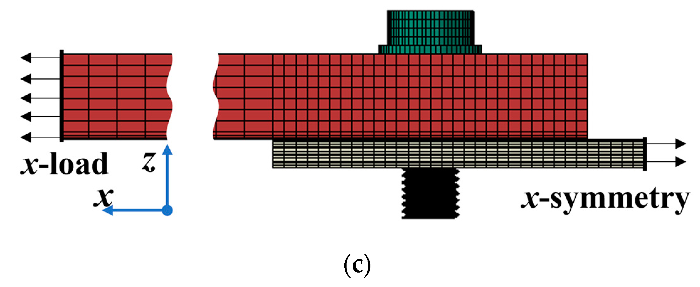
2. Numerical Model of Bolted Joints

Lapped joints are very common in architectural and mechanical structures. When subjected to transverse shear load, the bolt interface first slips; then, the bolt makes contact with the hole; finally, the bolt fractures. This work focuses on the shear damage of bolts under impact loading. The bolted joint chosen for this research consists of four S8.8 M20 bolts and three plates. The thicknesses of the plates are 30 mm and 10 mm, and the assembly clearance between the bolts and holes ( δ 0 ) is 1 mm. The test is performed using a hydraulic testing machine with a total capacity of 1000 kN. One end of the specimen is fixed, and a tensile displacement load is applied to the other end, with a displacement load rate of 1 mm/min [33]. According to EC3-1-8 [34], the standard value of pre-tension force corresponding to an S8.8 M20 bolt is F = 120 kN. The coefficient of friction is μ = 0.1. The tested components and finite element model are shown in Figure 1, with all components discretized by eight-node hexahedral elements. Mesh verification analysis was performed to obtain a reasonable mesh, providing reliable results in less computational time. A fine mesh was created at the region around the bolt, and according to the mesh verification results, the number of circumferential element divisions of the threads is 60, with a smallest element sizes of 0.14 mm and a total of 708,072 elements in the whole model. The material of the connected plates is Q355B alloy, with 45 steel for the bolt. Considering the effect of material strain rate during impact loading, the J-C model [35] was chosen for all material properties, the constitutive equation of which is expressed as
σ = ( A + B ε n ) ( 1 + C ln ε ˙ ε ˙ 0 ) [ 1 ( T T r T m T r ) m ]
ε = [ D 1 + D 2 exp ( D 3 σ σ 0 ) ] ( 1 + D 4 ln ε ˙ ε ˙ 0 ) [ 1 D 5 ( T T r T m T r ) ] .
Equation (1) is the J-C plasticity model, and Equation (2) is the J-C damage model, where σ is the flow stress; A is the yield stress under quasi-static conditions; B and n are strain-hardening parameters; m controls the temperature dependence; C is the strain-rate dependence; ε is the equivalent plastic strain; ε ˙ is the plastic strain rate; ε 0 ˙ is the reference strain rate; T is the absolute temperature; suffixes r and m indicate room and melting temperature, respectively; and D1, D2, D3, D4 and D5 are experimentally determined material damage parameters. The detailed material parameters are shown in Table 1.
As can be seen in Figure 2, in the experiment, the failure of a bolted joint subjected to transverse loads involves three stages. First, sliding occurs, and the sliding distance is the same as the assembly clearance. Secondly, collision occurs, during which the stiffness is gradually reduced. Finally, failure occurs. The failure mode was bolt shear fracture with the fracture surface located at the contact interface of the connected plates. In addition, according to EC-1993-1-8(EC-3) [38], the theoretical critical load of this lapped joint is 255.6 kN, which was calculated by FEM simulation as 256.4 kN with an error of 0.3%, and the experimental result was 257.6 kN with an error of 0.8%. The bolt deformation and critical load of the simulation results are in good agreement with the experimental results.

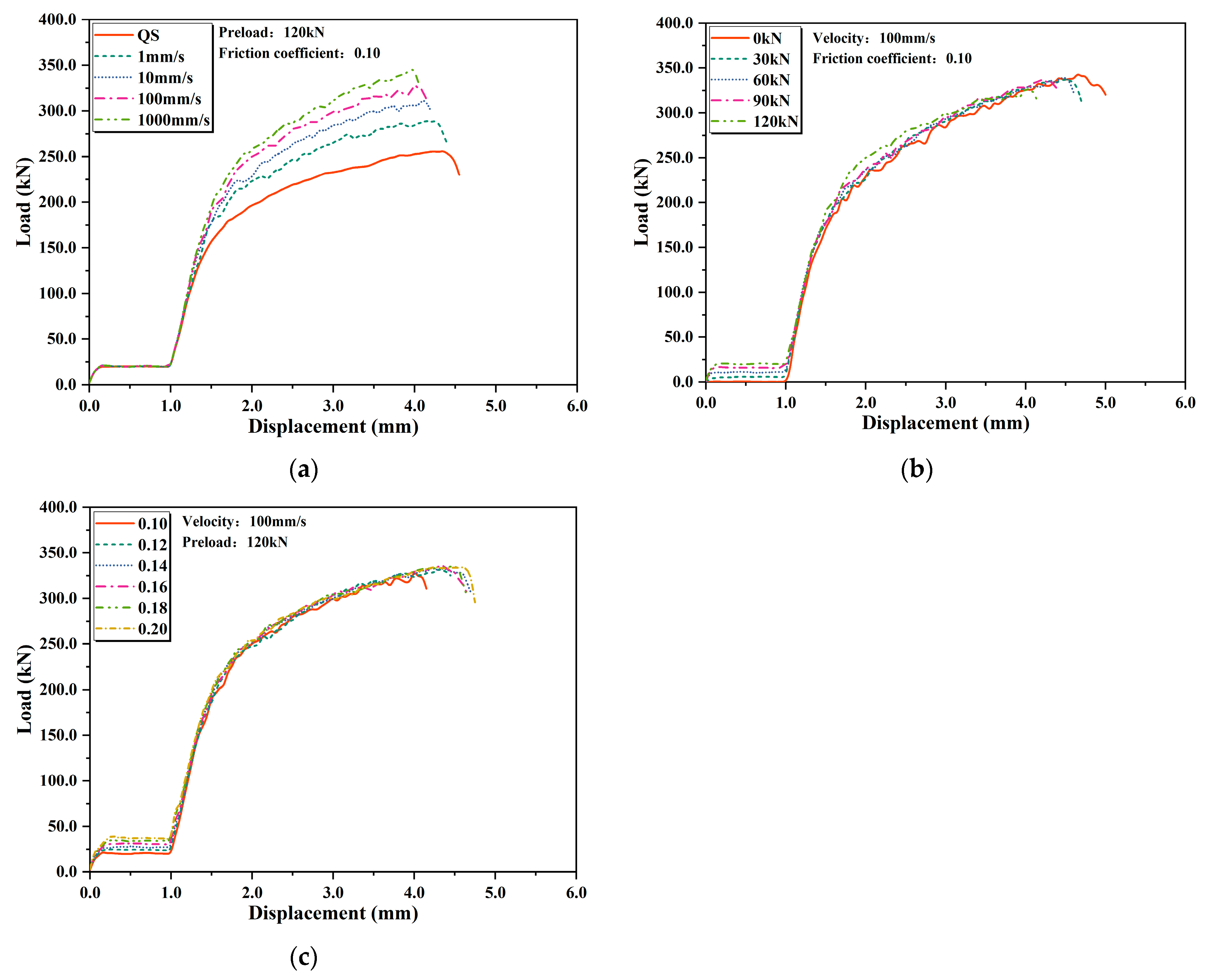
3. Parametric Analysis

In this section, the effects of impact velocity, preload force and friction coefficient on the impact response are discussed, and the results of the variable analysis of the three parameters are shown in Figure 3.
The plastic parameters of metallic materials are significantly influenced by the strain rate, so it makes sense to discuss the effect of impact velocity. In this paper, five working conditions from 1 mm/min(quasi-static) to 1000 mm/s are discussed, and the calculation results are similar to Sanborn’s summary [6]; as the velocity increases, the critical load of the bolted joint shows an increasing tendency, while the fracture displacement decreases. From the J-C model, it can be seen that metallic materials are subjected to both strain hardening and strain-rate hardening, and the stress and failure strain are linearly related to the logarithm of the normalized strain rate.
For bolted joints, the preload is an important parameter, and according to the available experimental data, the loss of preload in bolted joints during long-term service seems to be inevitable. In addition to affecting the magnitude of the interfacial friction, the preload also affects the stress distribution inside the entire bolted joint. In this paper, five preload conditions of 120 kN, 90 kN, 60 kN, 30 kN and 0 kN are discussed, and it is found that the critical load, as well as the fracture displacement, increases slightly as the preload decreases. The preload increases the tensile stresses inside the bolt, which is reflected in the J-C damage model as an effect of the stress triaxiality, leading to an increase in plastic strain accumulation.
Similar to the preload, the friction coefficient also affects the interfacial friction. In this paper, six cases of friction coefficient of 0.10, 0.12, 0.14, 0.16, 0.18 and 0.20 are discussed, and it can be seen that the larger the friction coefficient, the more the critical load and critical displacement increase.
Table 2 compares the critical loads at different velocities, preload forces and friction coefficients with the EC-3 prediction results, and it can be seen that EC-3 agrees with the quasi-static results but with a significant error in the impact results.

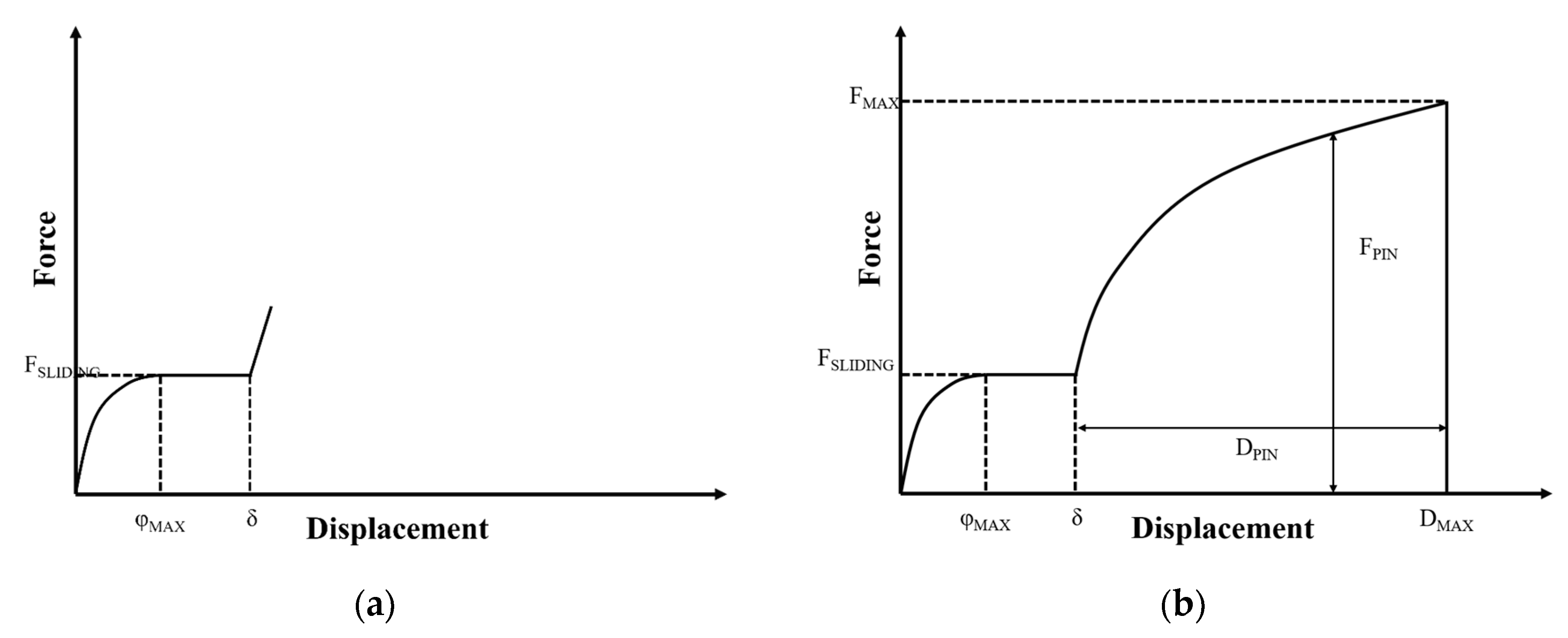
4. Dynamic Iwan Model

4.1. Analytical Development

Brake et al. [16] proposed a modified Iwan model (RIPP model) considering collision, and an illustrative drawing of the constitutive force as a function of displacement is shown in Figure 4a, which is expressed in the following form:
F RIPP = F PIN + F S
F S = 0 x f ρ ( φ ) d f + x x ρ ( φ ) d f
F PIN = π 4 E * L d
ρ ( φ ) = R φ χ [ H ( φ ) - H ( φ φ 2 ) ] + K δ ( φ φ 2 )
where FRIPP is the constitutive force of the RIPP model, FPIN describes the collision and FS describes the slide. In FS is the classical Iwan model, and FPIN is calculated by Hertz contact stiffness. Ρ(φ) is the Iwan density function, E is the contact stiffness, L is the contact length and d is the contact depth. In ρ(φ), H(φ) is the Heaviside function, δ(φ) is the Dirac function, φ MAX is the starting point of macroscopic slip, K is the tangential stiffness at the moment before macroscopic slip, and R and χ are parameters describing the power function. The RIPP model can describe the elastic collision of the bolt with the hole but cannot describe plastic deformation or even fracture failure under large sliding.
This paper proposes the DICF model, and the relationship between the constitutive force and the displacement is shown in Figure 4b, which was constructed with reference to the J-C model (Equations (1) and (2)), which means that multiple correction terms are used to modify the model under the reference operating conditions. The sliding part of the DICF model is still described by the classic Iwan model (Equation (4)), while the collision part is corrected with normalized velocity, normalized preload force and the normalized friction coefficient. The general form is expressed as
F MAX ( v , μ , p ) = F MAX ( v 0 , μ 0 , p 0 ) f 1 ( v * ) f 2 ( μ * ) f 3 ( P * )
D MAX ( v , μ , p ) = D MAX ( v 0 , μ 0 , p 0 ) f 4 ( v * ) f 5 ( μ * ) f 6 ( P * )
v * = v v 0 , μ * = μ μ 0 , P * = P P 0 ,
where v is the loading velocity, μ is the friction coefficient, P is the preload force, the suffix 0 indicates the reference state, and f1 to f6 are correction functions. δ 0 is the assembly clearance, and the complete expression of the DICF model is
F D ICF ( x ) = F S ( x ) x δ 0 F PIN ( x δ 0 ) δ 0 < x D MAX 0 D MAX x .
As shown in Figure 4b, D MAX is the critical displacement, corresponding to the displacement of the critical load ( F MAX ).

4.2. Parameter Identification

4.2.1. Sliding

Segalman et al. [13] and Li et al. [15] have provided detailed summaries for the parameter identification of the Iwan model (Fs). Displacement–load curves with different preload forces and friction coefficients were extracted based on a finite element simulation and fitted based on the Iwan model, whose corresponding Iwan destiny functions are power functions and truncated by the Dirac function, as shown in Figure 5a. The corresponding stiffness curves are shown in Figure 5b. The displacement–load curve is differentiated to the first order to obtain the displacement stiffness curve and make the following assumptions: 0   <   x   φ 1 , no yielding of the Jenkins elements, constant stiffness; φ 1   <   x   φ MAX , partial yielding of the Jenkins elements and a gradual decrease in stiffness;   φ MAX   x , complete yielding of the Jenkins elements and a reduction in stiffness to 0. A comparison between the Iwan model and the FEM results of the sliding stage is shown in Figure 6, and the Iwan model and the FEM model are in good agreement.

4.2.2. Collision

The impact velocity, friction coefficient and preload force in the DICF model are not coupled to each other, so their effects on the load curve can be extracted separately, normalized and fitted to obtain the expressions for f1 to f6. The selected normalized base parameters are v0 = 100 mm/s, μ = 0.1 and P = 120 kN; the curve under the reference condition is fitted with the asymptotic function (Boxlucas model); and the fitting result is shown in Figure 7. The general form of the Boxlucas model [39] is
F ( x ) = a 1 b x .
Equation (11) is a kind of asymptotic function, where parameter a controls the critical load and b controls the shape of the curve.
The fitted curves of the normalized parameters are shown in Figure 8. It can be seen that the normalized critical load is linearly related to the log-normalized velocity, the normalized preload force and the normalized friction coefficient; the normalized critical displacement is linearly related to the log-normalized velocity, the normalized preload force and the normalized friction coefficient. The specific expressions of Equation (7) and Equation (8) in the DICF model can then be expressed as
F MAX ( x * , v , μ , P ) = F MAX ( x * , v 0 , μ 0 , P 0 ) 1 + A v 1 ln ( v * ) 1 + A μ 1 μ * 1 + A P 1 P *
D MAX ( x * , v , μ , P ) = D MAX ( x * , v 0 , μ 0 , P 0 ) 1 + A v 2 ln ( v * ) 1 + A μ 2 μ * 1 + A P 2 P *

5. Results and Discussions

Figure 9 illustrates the displacement–load curves of the DICF model for different loading velocities, preload forces and friction coefficients. Comparison of Figure 9 and Figure 3 indicates that the DICF model can describe the effects of the above variables on the critical loads and critical displacements. Table 3 compares the critical load results from the DICF model and numerical calculations. The maximum error is −1.41% (v = 10 mm/s, P = 120 kN, μ = 0.1), and the minimum error is 0.17% (v = 1 mm/s, P = 120 kN, μ = 0.1). Compared to the EC-3 predictions (Table 2, maximum error of −26.17%), the DICF model is more accurate.
Compared to the quasi-static experiments, the strength of the bolted joints subjected to impact loading increases significantly, which is due to the strain-rate sensitivity of the material. For steel, the yield strength increases significantly with increasing strain rate. In addition, increasing the preload and friction coefficient both lead to an increase in friction, which results in a tendency for the critical load and critical displacement to increase. However, when preload is applied, the stiffness of the bolt increases, making it more difficult to absorb and buffer the energy from the external impact and resulting in a reduction in its ductility.

6. Conclusions

This paper presents simulation and modeling investigation of bolted joints subjected to impact loading. The effects of loading velocity, preload and friction coefficient on the strength and ductility of the joint are discussed. Finally, a dynamic Iwan model is proposed to describe the impact failure. The main conclusions are outlined as follows:
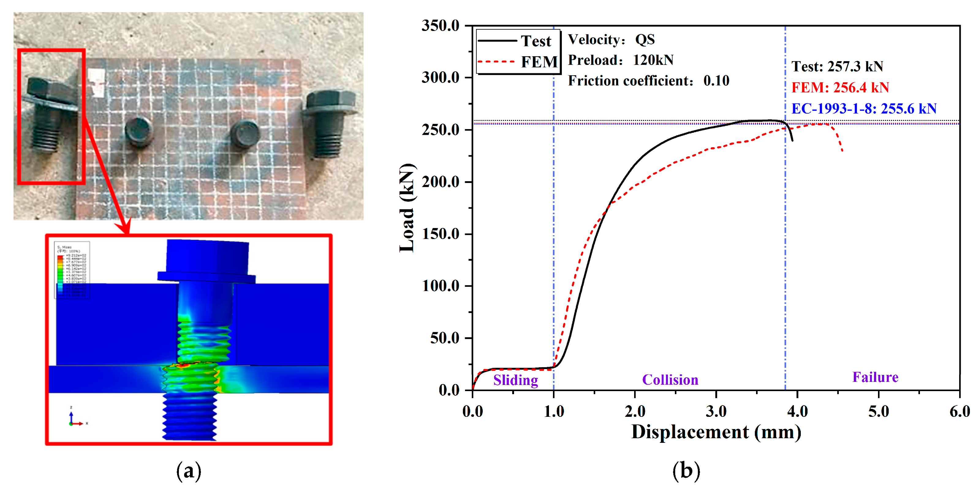
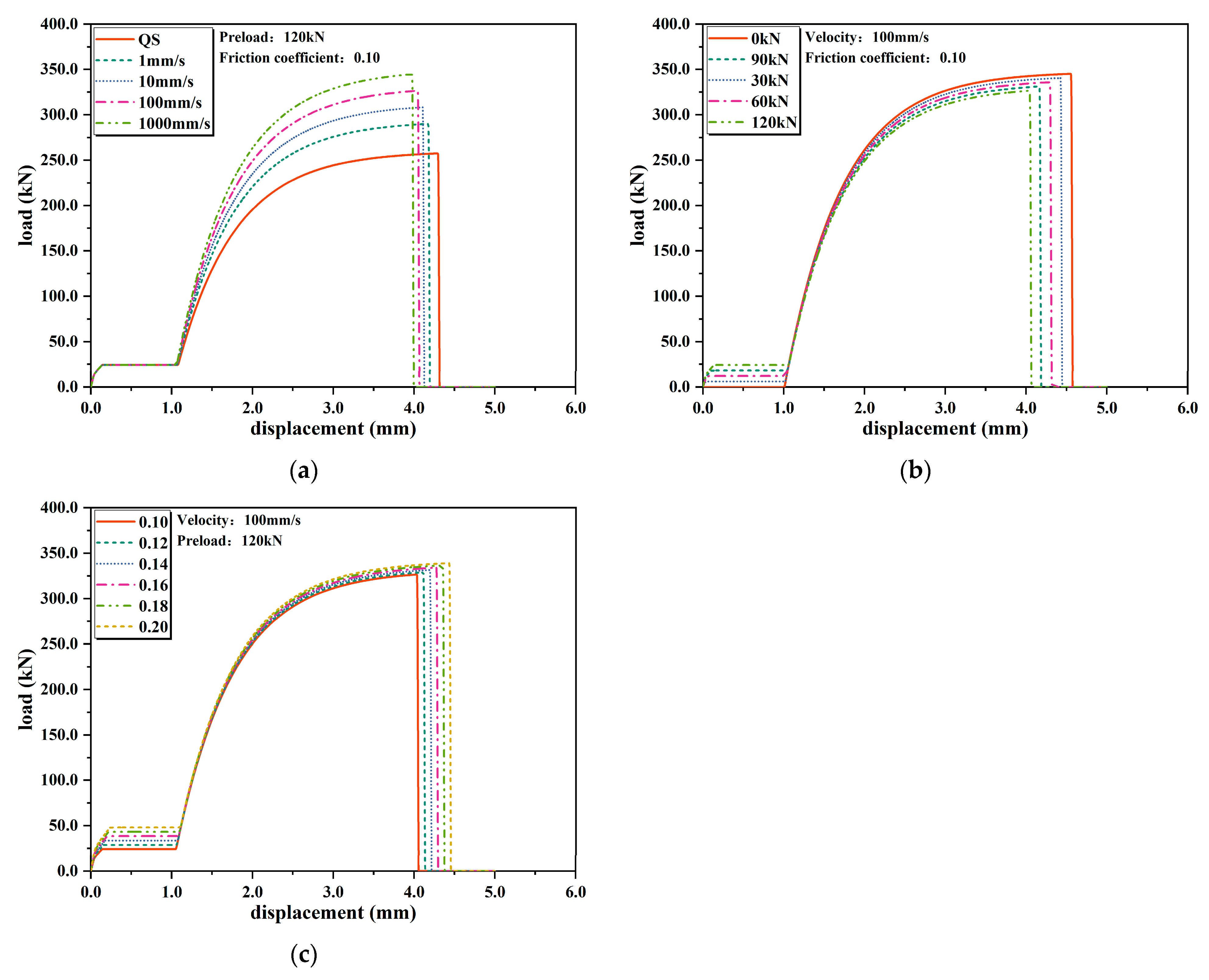
  • The response of bolted joints under impact loading consists of three main stages, namely slip, collision and bolt shear failure, and the developed fine finite element model can accurately simulate the form of damage, including the shear fracture of the bolt and the prediction of the critical load.
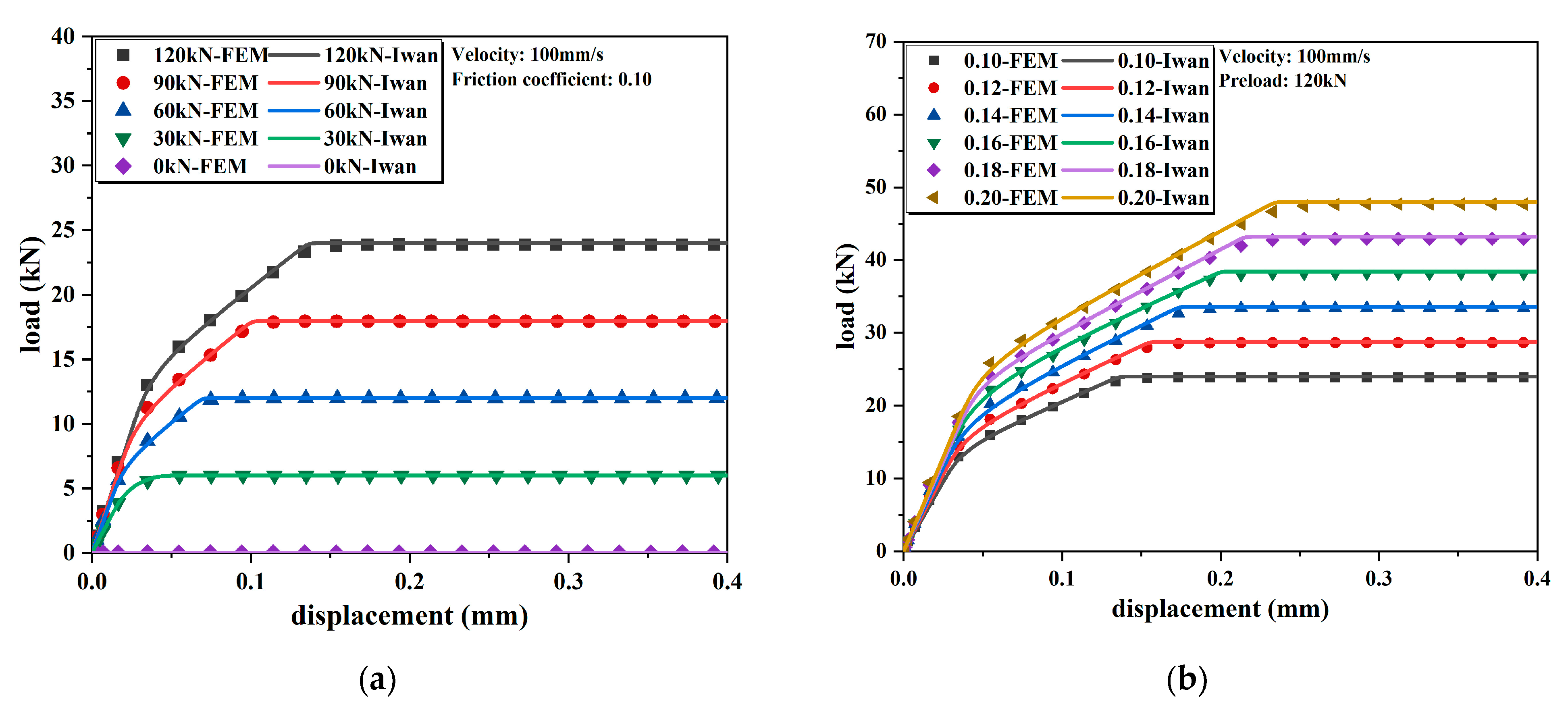
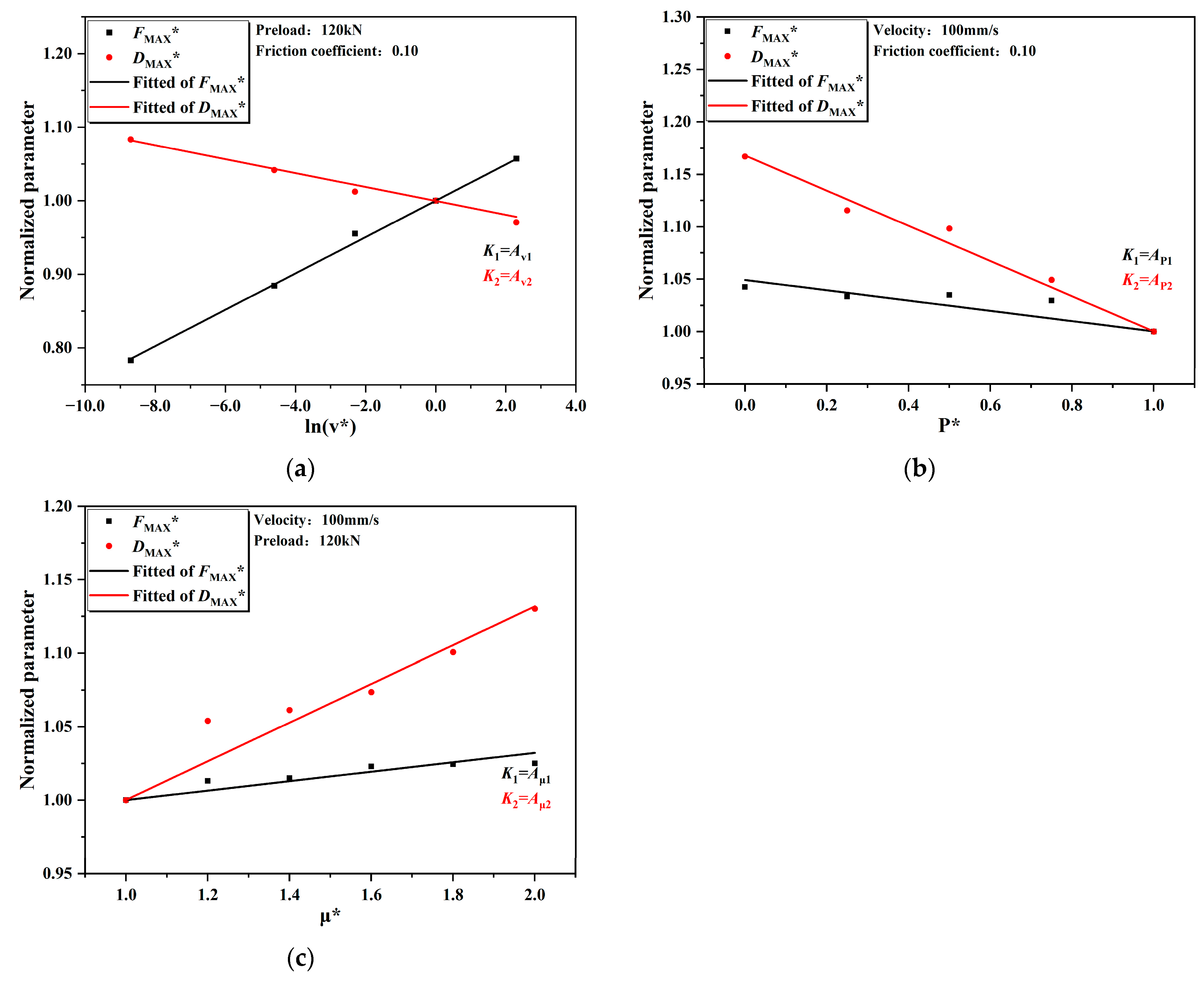
  • Numerical simulation results show that increases in velocity and friction coefficient lead to an increase in critical load, whereas preload leads to a decrease. In addition, critical load and critical displacement are linearly related to the normalized logarithmic velocity and the normalized preload and friction coefficient.
  • A dynamic Iwan model (DICF model) is proposed to describe the dynamic response of bolted joints under impact loading, the constitutive relationship is derived and a parameter identification procedure is proposed. The parameters can be obtained from experimental or numerical simulation results to accurately predict the force–displacement relationship for different velocities, preloads and friction coefficients.
  • Calculation of the refined finite element model is inefficient due to the contact interfaces and the complexity of the threads. In this study, a model is presented to describe the force–displacement relationship of bolted joints under impact loading more conveniently, which can be used in future studies to characterize the impact response of large structures containing bolted joints.

Author Contributions

Conceptualization, H.C. and Z.H.; methodology, H.C.; software, H.C. and J.K.; validation, Z.H.; formal analysis, H.C.; investigation, H.C. and Z.H.; resources, H.C. and Z.H.; data curation, H.C.; writing—original draft preparation, H.C.; writing—review and editing, Z.H.; visualization, H.C.; supervision, Z.H.; project administration, Z.H.; funding acquisition, J.L. All authors have read and agreed to the published version of the manuscript.

Funding

This research was funded by the Outstanding Young Scientist Foundation of Sichuan Province of China (grant number 2023NSFSC1913) and the National Natural Science Foundation of China (grant number 12072268).

Data Availability Statement

The original contributions presented in the study are included in the article. Further inquiries can be directed to the authors.

Acknowledgments

The authors gratefully acknowledge the support provided by the Outstanding Young Scientist Foundation of Sichuan Province of China (2023NSFSC1913) and the National Natural Science Foundation of China (12072268).

Conflicts of Interest

The authors declare no conflicts of interest.

References

  1. Du, F.; Wu, S.; Xu, C.; Yang, Z.; Su, Z. Electromechanical Impedance Temperature Compensation and Bolt Loosening Monitoring Based on Modified Unet and Multitask Learning. IEEE Sens. J. 2023, 23, 556–4567. [Google Scholar] [CrossRef]
  2. Warren, M.; Antoniou, A.; Stewart, L. A review of experimentation and computational modeling of dynamic bolt fracture. J. Constr. Steel Res. 2022, 194, 107293. [Google Scholar] [CrossRef]
  3. Zheng, Q.; Guo, Y.; Wei, Y.; Wang, Y.; Wang, X. Loosening of steel threaded connection subjected to axial compressive impact loading. Int. J. Impact Eng. 2020, 144, 103662. [Google Scholar] [CrossRef]
  4. Horsfall, I.; Hansen, B.; Carr, D. Security of Bolted Joints during Explosive Loading. Int. J. Veh. Struct. Syst. 2011, 3, 107. [Google Scholar] [CrossRef]
  5. Gao, S.; Li, J.; Guo, L.; Bai, Q.; Li, F. Mechanical properties and low-temperature impact toughness of high-strength bolts after elevated temperatures. J. Build. Eng. 2022, 57, 104851. [Google Scholar] [CrossRef]
  6. Tyas, A.; Warren, J.; Stoddart, E.; Davison, J.; Tait, S.; Huang, Y. A methodology for combined rotation-extension testing of simple steel beam to column joints at high rates of loading. Exp. Mech. 2012, 52, 1097–1109. [Google Scholar] [CrossRef]
  7. Ribeiro, J.; Santiago, A.; Rigueiro, C.; Barata, P.; Veljkovic, M. Numerical assessment of T-stub component subjected to impact loading. Eng. Struct. 2016, 106, 450–460. [Google Scholar] [CrossRef]
  8. Sanborn, M.J. Experimental Methods for Understanding the Behavior and Residual Capacity of Bolts and Steel Bolted Connections under Impulsive Loads. Ph.D. Dissertation, Georgia Institute of Technology, Atlanta, GA, USA, 2018. [Google Scholar]
  9. Sanborn, M.J.; Stewart, L.K. Method for evaluating impulsive shear and residual capacity behavior of bolted connections. Eng. Struct. 2020, 220, 110372. [Google Scholar] [CrossRef]
  10. Sanborn, M.J.; Stewart, L.K. Behavior of slip-critical bolted connections subjected to impulsive loads. Int. J. Impact Eng. 2020, 143, 103501. [Google Scholar] [CrossRef]
  11. Fransplass, H.; Langseth, M.; Hopperstad, O. Experimental and numerical study of threaded steel fasteners under combined tension and shear at elevated loading rates. Int. J. Impact Eng. 2015, 76, 118–125. [Google Scholar] [CrossRef]
  12. Ren, T.; Suo, T.; Meng, Y.; Gao, Y.; Wang, C.; Li, Y. On dynamic behavior and failure of high lock bolted joints: Testing, analysis and predicting. Eur. J. Mech.-A/Solids 2022, 96, 104681. [Google Scholar] [CrossRef]
  13. Wagner, T.; Heimbs, S.; Burger, U. A simplified and semi-analytical bolted joint model for crash and impact simulations of composite structures. Compos. Struct. 2020, 233, 111628. [Google Scholar] [CrossRef]
  14. Song, Y.; Wang, J.; Uy, B.; Li, D. Experimental behaviour and fracture prediction of austenitic stainless steel bolts under combined tension and shear. J. Constr. Steel Res. 2020, 166, 105916. [Google Scholar] [CrossRef]
  15. Cao, Z.; Brake, M.; Zhang, D. The failure mechanisms of fasteners under multi-axial loading. Eng. Fail. Anal. 2019, 105, 708–726. [Google Scholar] [CrossRef]
  16. Warren, M.; Sanborn, M.J.; Stewart, L.K. Characterization of A325 Structural Bolts Subjected to Impulsive Loads. In Proceedings of the ASME 2021 International Mechanical Engineering Congress and Exposition, Virtual, 1–5 November 2021; Volume 12, p. V012T12A002. [Google Scholar]
  17. Jalali, H.; Jamia, N.; Friswell, M.I.; Khodaparast, H.H.; Taghipour, J. A generalization of the Valanis model for friction modelling. Mech. Syst. Signal Process. 2022, 179, 109339. [Google Scholar] [CrossRef]
  18. Mathis, A.T.; Balaji, N.N.; Kuether, R.J.; Brink, A.R.; Brake, M.R.; Quinn, D.D. A review of damping models for structures with mechanical joints. Appl. Mech. Rev. 2020, 72, 040802. [Google Scholar] [CrossRef]
  19. Marques, F.; Woliński, Ł.; Wojtyra, M.; Flores, P.; Lankarani, H.M. An investigation of a novel LuGre-based friction force model. Mech. Mach. Theory 2021, 166, 104493. [Google Scholar] [CrossRef]
  20. Jia, T.; Liu, J.; Wang, Y.; Li, C.; Zhang, H. An improved LuGre friction model and its parameter identification of structural interface in thermal environment. Mech. Syst. Signal Process. 2024, 216, 111468. [Google Scholar] [CrossRef]
  21. Robat, A.B.; Arezoo, K.; Alipour, K.; Tarvirdizadeh, B. Dynamics modeling and path following controller of tractor-trailer-wheeled robots considering wheels slip. ISA Trans. 2024, 148, 45–63. [Google Scholar] [CrossRef]
  22. Yin, R.; Xue, B.; Brousseau, E.; Geng, Y.; Yan, Y. Characterizing the electric field- and rate-dependent hysteresis of piezoelectric ceramics shear motion with the Bouc-Wen model. Sens. Actuators A Phys. 2024, 367, 115044. [Google Scholar] [CrossRef]
  23. Maleki, M.; Ahmadian, H.; Rajabi, M. A modified Bouc-Wen model to simulate asymmetric hysteresis loop and stochastic model updating in frictional contacts. Int. J. Solids Struct. 2023, 269, 112212. [Google Scholar] [CrossRef]
  24. Mishra, M.K.; Samantaray, A.K.; Chakraborty, G. Fractional-order Bouc-wen hysteresis model for pneumatically actuated continuum manipulator. Mech. Mach. Theory 2022, 173, 104841. [Google Scholar] [CrossRef]
  25. Song, Y.; Hartwigsen, C.; McFarland, D.; Vakakis, A.F.; Bergman, L. Simulation of dynamics of beam structures with bolted joints using adjusted Iwan beam elements. J. Sound Vib. 2004, 273, 249–276. [Google Scholar] [CrossRef]
  26. Li, Y.; Hao, Z. A six-parameter Iwan model and its application. Mech. Syst. Signal Process. 2016, 68, 354–365. [Google Scholar] [CrossRef]
  27. Segalman, D.J.; Starr, M.J. Inversion of Masing models via continuous Iwan systems. Int. J. Non-Linear Mech. 2008, 4, 74–80. [Google Scholar] [CrossRef]
  28. Wang, D.; Xu, C.; Fan, X.; Wan, Q. Reduced-order modeling approach for frictional stick-slip behaviors of joint interface. Mech. Syst. Signal Process. 2018, 103, 131–138. [Google Scholar] [CrossRef]
  29. Brake, M. A reduced Iwan model that includes pinning for bolted joint mechanics. Nonlinear Dyn. 2017, 87, 1335–1349. [Google Scholar] [CrossRef]
  30. Shen, M.; Yang, X.; Gao, C.; Yang, J.; Shi, R.; Guo, P. Modeling and analyzing the influence of slip velocity on joint surface. Int. J. Non-Linear Mech. 2024, 165, 104798. [Google Scholar] [CrossRef]
  31. Ranjan, P.; Pandey, A.K. Modeling of pinning phenomenon in Iwan model for bolted joint. Tribol. Int. 2021, 161, 107071. [Google Scholar] [CrossRef]
  32. Li, D.; Botto, D.; Xu, C.; Liu, T.; Gola, M. A micro-slip friction modeling approach and its application in underplatform damper kinematics. Int. J. Mech. Sci. 2019, 161, 105029. [Google Scholar] [CrossRef]
  33. Wang, P.; Wulan, T.; Liu, M.; Qu, H.; You, Y. Shear behavior of lap connection using one-side bolts. Eng. Struct. 2019, 186, 64–85. [Google Scholar] [CrossRef]
  34. BS EN 1993-1-8; European Committer for Standardization. Eurocode3: Design of Steel Structures, Part1–8: Design of Joints. The Spanish Association for Standardization and Certification: Madrid, Spain, 2005.
  35. Sirigiri, V.K.R.; Gudiga, V.Y.; Gattu, U.S.; Suneesh, G.; Buddaraju, K.M. A review on Johnson Cook material model. Mater. Today Proc. 2022, 62, 3450–3456. [Google Scholar] [CrossRef]
  36. Wei, G.; Zhang, W.; Deng, Y. Identification and validation of constitutive parameters of 45 Steel based on J-C model. J. Vib. Shock 2019, 38, 173–178. [Google Scholar]
  37. Chen, G.; Chen, Z.; Xu, W. Investigation on the J-C ductile fracture parameters of 45 steel. Explos. Shock Waves 2007, 27, 131–135. [Google Scholar]
  38. Li, L.; Haung, B.; Xiao, X.; Zhu, Y.; Xu, T. Behavior of dynamic material Q355B steel based on the Johnson-Cook model. J. Vib. Shock 2020, 39, 231–237. [Google Scholar]
  39. Cong, L.; Ren, M.; Shi, J.; Yang, F.; Guo, G. Experimental investigation on performance deterioration of asphalt mixture under freeze–thaw cycles. Int. J. Transp. Sci. Technol. 2020, 9, 218–228. [Google Scholar] [CrossRef]
Figure 1. Model of a bolted joint. (a) Test system “Reprint with permission [33]; 2024, Elsevier”; (b) FEM model and (c) loading conditions.
Buildings 14 02572 g001aBuildings 14 02572 g001b
Figure 2. Comparison of EC-1993-1-8 with simulation and experimental results. (a) Bolt shear fracture failure; (b) displacement–load curve.
Buildings 14 02572 g002
Figure 3. Results of parametric analysis: influence of (a) impact velocity, (b) preload force and (c) friction coefficient on displacement–load curves.
Buildings 14 02572 g003
Figure 4. Illustrative drawing of the constitutive force as a function of displacement for (a) the RIPP model and (b) the DICF model.
Buildings 14 02572 g004
Figure 5. (a) Iwan destiny function and (b) displacement–stiffness curve.
Buildings 14 02572 g005
Figure 6. Comparison between Iwan model and the FEM results for different (a) preload forces and (b) friction coefficients.
Buildings 14 02572 g006
Figure 7. Fitting results of the collision stage under reference parameters.
Buildings 14 02572 g007
Figure 8. Fitting of normalized critical load (FMAX*) and critical displacement (DMAX*) under different (a) impact velocities, (b) preload forces and (c) friction coefficients.
Buildings 14 02572 g008
Figure 9. Displacement–load curves of the DICF model under different (a) velocities,(b) preload forces and (c) friction coefficients.
Buildings 14 02572 g009
Table 1. Material parameters of the components [36,37,38].
ComponentMaterialE (GPa)νΡ (kg/m3)A (MPa)
PlatesQ355B steel2060.287850339.45
Bolt and Nut45 steel2060.287850714
B (MPa)CnmTm (°C)Tr (°C)
6200.0450.4120.661800293
5630.0370.520.71808293
ε ˙ (s−1)D1D2D3D4D5
1.33 × 10−30.816.05−7.09−0.0032.0
8.33 × 10−40.100.761.570.005−0.84
Table 2. Comparison of the numerical analysis results with the EC-3 prediction results.
Velocity (mm/s)Preload (kN)Friction
Coefficient
Critical Load (kN)
SimulationEC-3Error (%)
QS1200.10256.4255.6−0.31
11200.10289.6255.6−11.74
101200.10312.8255.6−18.29
1001200.10327.4255.6−21.93
10001200.10346.2255.6−26.17
100900.10337.1255.6−24.18
100600.10338.8255.6−24.56
100300.10338.3255.6−24.45
10000.10341.3255.6−25.11
1001200.12331.7255.6−22.94
1001200.14332.3255.6−23.08
1001200.16334.9255.6−23.68
1001200.18335.4255.6−23.79
1001200.20335.6255.6−23.84
Table 3. Comparison of the numerical analysis results with the DICF model prediction results.
Velocity (mm/s)Preload (kN)Friction
Coefficient
Critical Load (kN)
SimulationDICF ModelError (%)
QS1200.10256.4257.50.43
11200.10289.6290.10.17
101200.10312.8308.4−1.41
1001200.10327.4326.6−0.24
10001200.10346.2344.7−0.43
100900.10337.1331.3−1.72
100600.10338.8336.0−0.83
100300.10338.3340.50.65
10000.10341.3345.01.08
1001200.12331.7329.2−0.75
1001200.14332.3331.7−0.18
1001200.16334.9334.2−0.21
1001200.18335.4336.70.38
1001200.20335.6339.11.04
Disclaimer/Publisher’s Note: The statements, opinions and data contained in all publications are solely those of the individual author(s) and contributor(s) and not of MDPI and/or the editor(s). MDPI and/or the editor(s) disclaim responsibility for any injury to people or property resulting from any ideas, methods, instructions or products referred to in the content.

