Article

Seismic Performance of Precast Steel Beam-Column Joint with Bolted Connection

1
Institute of Systems Engineering, China Academy of Engineering Physics, Mianyang 621999, China
2
Chengdu Science and Technology Development Center, China Academy of Engineering Physics, Chengdu 610213, China
*
Author to whom correspondence should be addressed.
Buildings 2024, 14(8), 2588; https://doi.org/10.3390/buildings14082588
Submission received: 6 May 2024 / Revised: 3 July 2024 / Accepted: 25 July 2024 / Published: 22 August 2024
(This article belongs to the Special Issue Advanced Research and Prospect of Buildings Seismic Performance)

Abstract

:
This paper introduces a modular, assembled steel beam-column flange connection joint that efficiently connects prefabricated beams and columns using high-strength bolts. It enables the rapid repair of damaged joints after earthquakes by replacing flange connectors and high-strength bolt groups. Four joint specimens with varying thicknesses and lengths of the inner flange sleeve, scaled at a 1:2 ratio, were fabricated to evaluate performance. These specimens were subjected to low circumferential reciprocal loads to investigate damage modes, hysteresis curves, skeleton curves, ductility performance, energy dissipation capacity, and seismic performance, including stiffness degradation. The test and analysis results reveal that the primary failure mode is characterized by bulging of the flange jacket cover, with damage concentrated in the plastic hinge zone at the beam end. The flange connection joint exhibits excellent load-bearing, rotational, and energy dissipation capacities. The ‘secondary strengthening’ feature significantly enhances joint load-bearing capacity, ductility performance, and energy dissipation, increasing overall safety redundancy. Increasing the thickness and length of the flange connector substantially improves seismic performance and enlarges the plastic development area.

1. Introduction

Steel structures provide several advantages, including superior seismic performance and recyclability. The adoption of modular, assembled steel structures promotes the industrialization and modernization of the construction industry. However, the development of modular, assembled steel structures started relatively late, and technological progress lags behind international research standards, particularly in modular assembled high-rise steel structures [1,2]. The design and construction of beam-column connection joints are pivotal in steel structures, significantly influencing the mechanical properties of the entire frame. Notably, during the 1994 Northridge earthquake in the United States and the 1995 Kobe earthquake in Japan, many beam-column welded connections experienced brittle damage. In these instances, the beam flange welds fractured, and surrounding plates tore, leading to structural instability and the collapse of steel frames [3,4].
The primary method for connecting square tube columns and H-beams on construction sites currently involves conventional welding or bolt welding. However, on-site welding often presents quality challenges, leading to issues such as excessive residual deformation, reduced fatigue life, and decreased construction efficiency. These challenges hinder the widespread adoption of steel structure assembly, modularization, and batch production. In response, researchers worldwide have increasingly turned to bolted connections as alternatives to welded joints when investigating the seismic performance of structural connections. The closed section of square steel tubes, however, poses challenges for field bolt assembly with H-beams. Consequently, numerous scholars worldwide have embarked on innovative studies to explore novel beam-column bolted joint connections.
Various studies are currently focused on innovating the connection forms of beam-column bolted joints. Waqas et al. [5] conducted static and cyclic loading tests on square steel tube columns and H-shaped steel beam joints connected with blind eye bolts and end plates. Their study aimed to investigate the impact of joint parameters on the seismic performance of these connections. Nunez et al. [6,7,8] proposed a novel connection between wide flange beams and tubular column sections and developed improved formulas to compute the optimal thickness of end plates. They designed and fabricated three full-scale specimens to investigate the effect of end plates on the overall performance of bolted joints. Maali [9] conducted an investigation involving six full-scale beam-to-column connections with bolted end plates. The study, divided into two groups, employed both experimental and numerical methods. It focused on analyzing the impact of vertical and horizontal stiffeners on the static behavior of semi-rigid beam-to-column bolted connections. Ma et al. [10] introduced an innovative inter-module connection (IMC) with a cross-shaped plug-in connector and provided a mechanical model of this connection. Their study considered factors such as axial compression ratios, beam and column sections, and the thickness of the tenon plate. They investigated how these factors influenced the connection’s performance using numerical simulations. Zhiwei Zhang et al. [11] designed a novel column-column-beam joint with variable beam height and conducted a comprehensive analysis of its mechanical properties. They evaluated the ultimate bearing capacity, stiffness characteristics, failure modes, and hysteretic behavior of the joint under low cyclic loading. Yang et al. [12] introduced a modular steel construction beam-to-beam joint with blind bolted connections. To assess its seismic performance, they conducted quasi-static tests on four full-scale T-shaped joints with different construction forms. These tests provided data on the failure mode, strength, stiffness, ductility, and energy dissipation of the joints. Li et al. [13,14,15] conducted experimental studies and theoretical analyses on the load-carrying capacity and rotational stiffness of several rectangular steel tube column-H-beam end plate one-way bolt connections. Zhang et al. [16,17,18,19] proposed several square steel tube column-H-beam bolted joint forms, carried out detailed finite element analysis and experimental studies, and derived theoretical calculation formulas. Wang et al. [20,21,22,23] conducted a comprehensive investigation into the mechanical properties of various internal sleeve combination bolted joints. They employed both experimental tests and numerical simulations, revealing that these joints exhibited excellent hysteretic performance, substantial ductility, and high energy dissipation capacity under reciprocating loads. Han et al. [24,25] conducted extensive numerical analyses and experimental studies on the mechanical properties of cast steel joints connecting square steel tube columns and H-beams. Their investigations covered both monotonic and reciprocating loads, analyzing load transfer paths and distribution patterns in beam-column nodes subjected to bending moments. They also introduced a load-bearing capacity theory based on the principle of deformation coordination. Liu et al. [26,27,28,29,30,31] proposed various configurations of beam-column bolted joints with column holders. They conducted numerous cyclic loading tests and used finite element analysis on various parameters to examine the damage mechanisms and seismic performance of these joints. As a result, they derived theoretical calculation equations for these joints.
This study introduces a novel all-bolt joint for square steel tube column flange-connected H-beams, referred to as the “flange connection joint”. This innovative design allows for the assembly of components using exclusively bolts while on-site, eliminating the need for on-site welding. This improvement greatly enhances assembly efficiency. Additionally, the components of this joint eliminate the need for creating holes in the square steel tubular (SST) column, ensuring the integrity of the column section. The joint also offers the advantage of rapid repair after an earthquake by simply replacing the flange connectors and high-strength bolts. The seismic behavior of four specimens, with varying thicknesses and lengths of the flange connection, was evaluated experimentally.

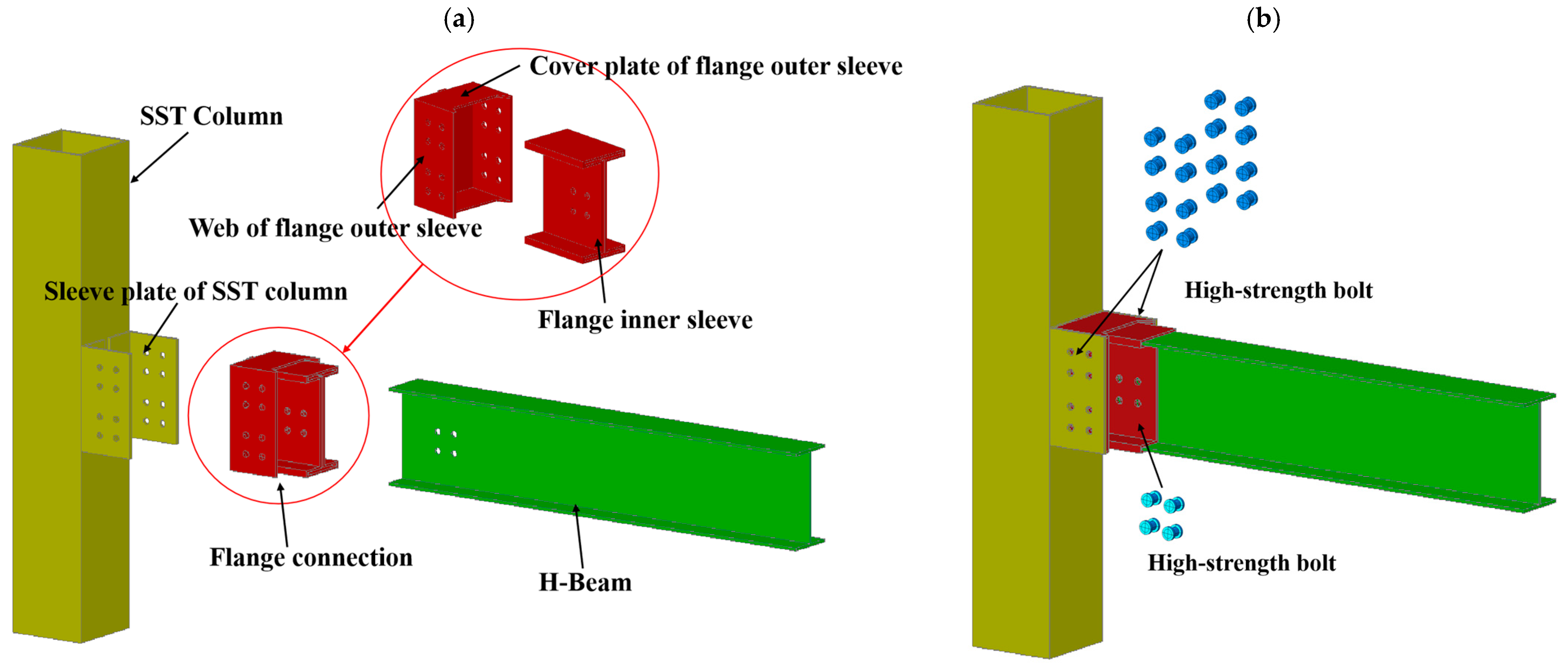
2. Construction of the Joint

The innovative joint consists of three modules: a square steel tubular (SST) column with sleeve plates, a flange connection, and an H-beam, as shown in Figure 1. On-site construction is simplified by assembling only three modules with a few bolts, significantly increasing assembly speed. The SST column with sleeve plates consisted of an SST column and two sleeve plates with partially predetermined bolt holes welded to the column wall. The flange connection consisted of a flange inner sleeve and a flange outer sleeve. The flange outer sleeve was welded to the upper and lower cover plates and the web on both sides. The H-beam had partially predetermined bolt holes. The flange connection was attached to the SST column with sleeve plates using eight high-strength bolts on each side. The flange connection was attached to the H-beam using four high-strength bolts. The bolt connection was designed as no slip connection based on the AISC 341 [32]. The precast beam-column joint proposed in this study is a ductile joint. The specimens were designed to exhibit flexural damage. To reduce stress in the plastic zone of the H-beam, a flange connection was used. To ensure that the main damage and yielding of the H-beam would spread to other parts, the length of the flange connection was determined to balance the yielding moment demand between the plastic zone and the beam section.

3. Test Design

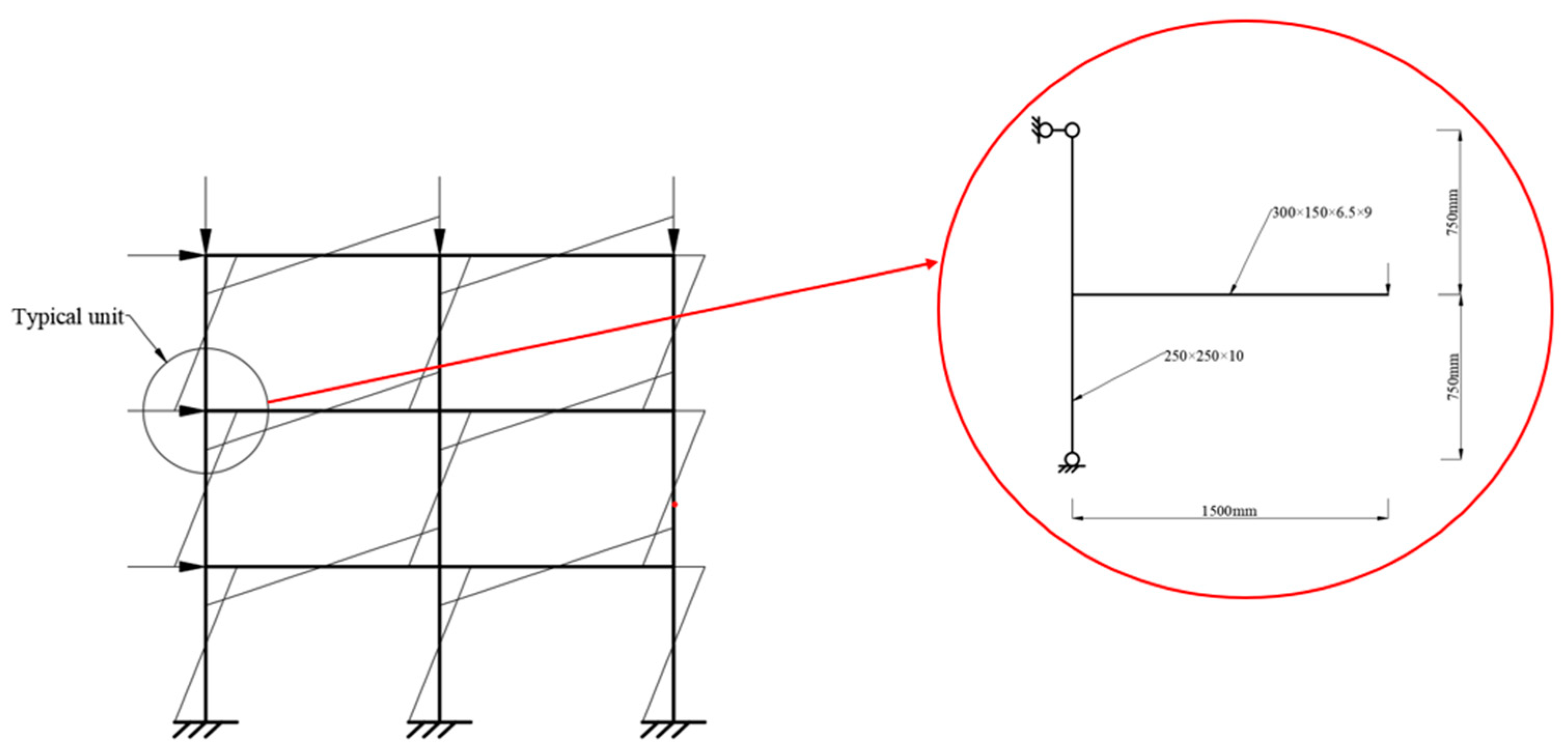
3.1. Specimen Design

In compliance with Chinese design codes [33,34], four specimens with varying thicknesses and lengths of the flange inner sleeve were designed. The square steel tubular (SST) has a cross-sectional dimension of 250 × 10 mm, while the H-shaped beam had a cross-sectional dimension of H300 × 150 × 6.5 × 9 mm. The materials used for the column, flange connection, and beam were Q345B steel [35]. High-strength S10.9 M20 bolts were used [36], with standard bolt holes 2 mm larger than the bolt shank diameter (i.e., 22 mm for M20 bolts). Before testing, a torque wrench applied a pretension of 155 kN to the bolts. Additionally, the clearance required for the flange inner sleeve and beam mounting was considered. The specimen numbers and cross-section parameters are detailed in Table 1. To accommodate the beam’s bending point in the steel frame, the distance from the joint beam end to the column axis was set at 1500 mm. The column height was set at 1500 mm, considering laboratory constraints. The joint beam-column cross-section and geometric length are shown in Figure 2.

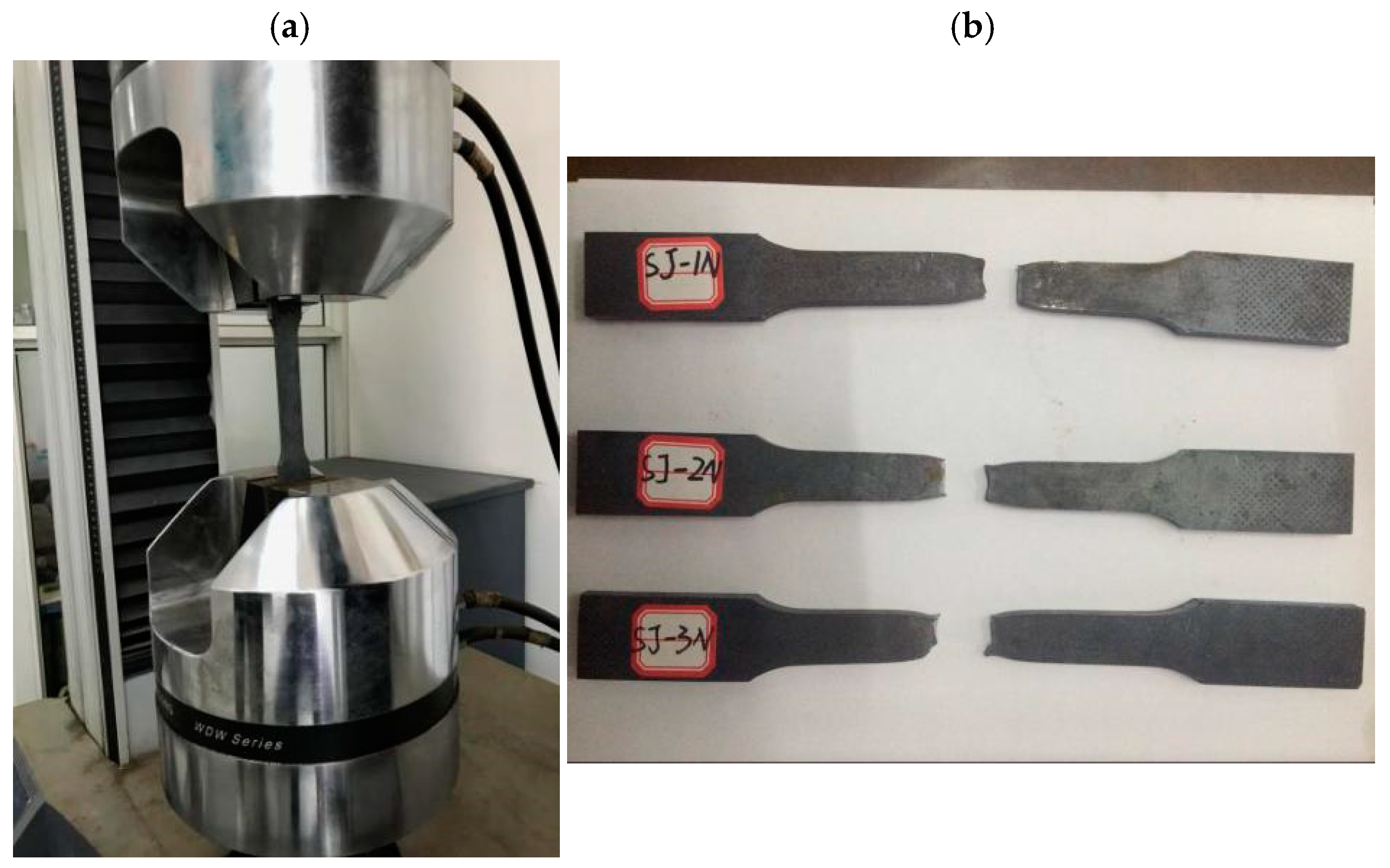
3.2. Material Properties

In compliance with relevant standards and references [37], tensile specimens were prepared by cutting them from square steel tube columns, H-beams, and other steel plates at their respective positions. This process resulted in three tensile specimens, each with different thickness parameters, yielding a total of eighteen specimens across six categories. Uniaxial stress–strain full-curve tensile tests were conducted on these specimens using a universal testing machine [38], as depicted in Figure 3. The mechanical property parameters for each type of steel are detailed in Table 2.

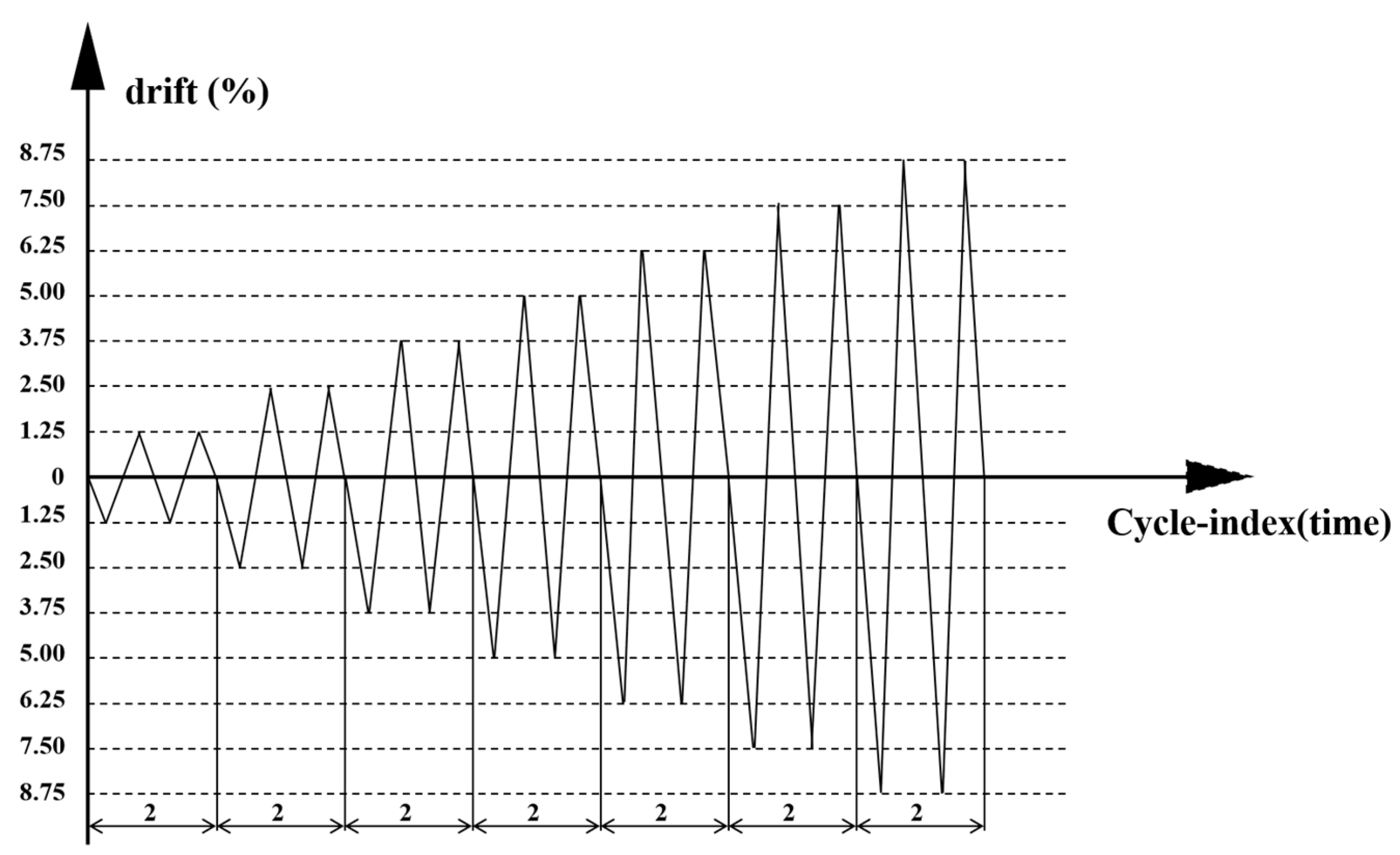
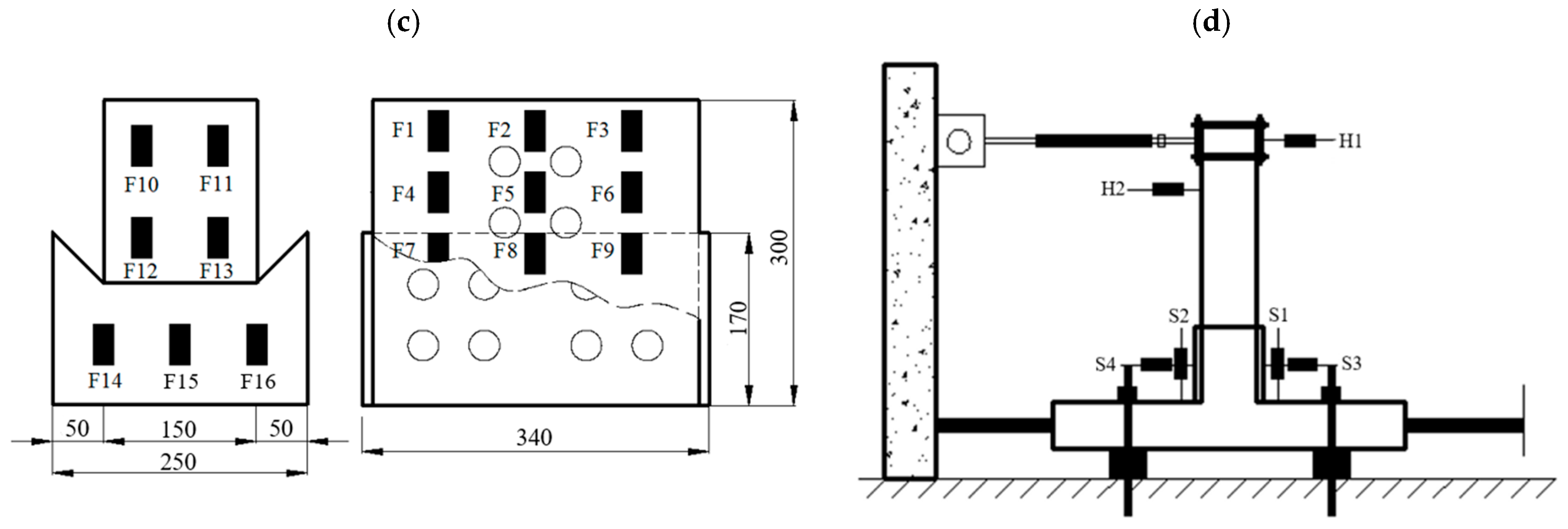
3.3. Test Loading System

Figure 4 shows a schematic of the loading setup. The column was oriented horizontally and connected to a hydraulic jack at its top. The bottom of the column was attached to the reaction frame with a fixed hinge. Horizontal displacement was constrained by limit bolts. An actuator applied cyclic loading to the beam end [29]. The steel blocks were used to prevent ground unevenness from causing misalignment of the joints, which could affect the test data. Ground bolts and horizontal limit bolts were applied to secure the steel column. Once the steel column was fixed, a horizontal force was applied at the end of the steel beam. This force was transferred to the steel column through the flange connection and the column sleeve plate, allowing for the observation of force changes in the beam-column joint through the test phenomena. Before the test, a torque wrench applied a pre-tension force of 155 kN to the bolts. A hydraulic jack then applied an axial load equivalent to 30% of the column section’s yield strength to the top of the column, maintained throughout the test. Displacement-controlled variable amplitude loading was conducted following the ANSI/AISC 341 standard [38], as shown in Figure 5. The loading process was halted when any of the following conditions were met: (1) significant plastic deformation in the steel beams with the formation of plastic hinges, (2) the load dropped below 85% of the peak value, or (3) weld damage in the beam-column joint area exceeded 70%. Additionally, loading was stopped if the beam-end load substantially decreased or if the specimen could not stably support the load.

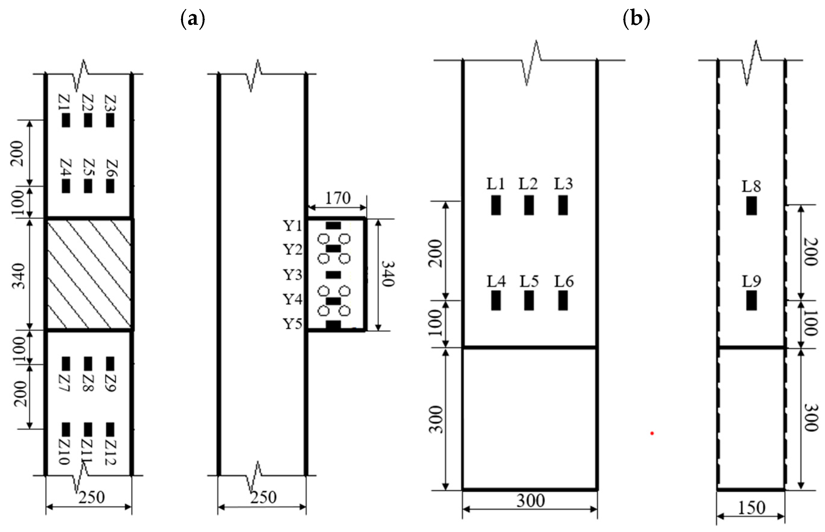
3.4. Measurement Program

Figure 6 shows the arrangement of measurement points for strain in the node domain and main structural components during the test. Zi are strain measurement points inside the square steel tube, Yi are strain measurement points between the bolts of the column flange sleeve, Li are measurement points on the H-beam, and Fi are measurement points on the flange connector. F1–F9 are measurement points on the flange inner sleeve web, F10–F13 are on the flange inner sleeve flange, and F14–F16 are on the flange outer cover, with the specific layout shown in Figure 6a–c. The displacement meters H1–H2 measured the horizontal displacement of the loaded end of the H-beam, S1–S2 measured the relative sliding displacement of the flange joint, and S3–S4 measured the deformation of the square steel column wall, as shown in Figure 6d [29].

4. Test Results and Analysis

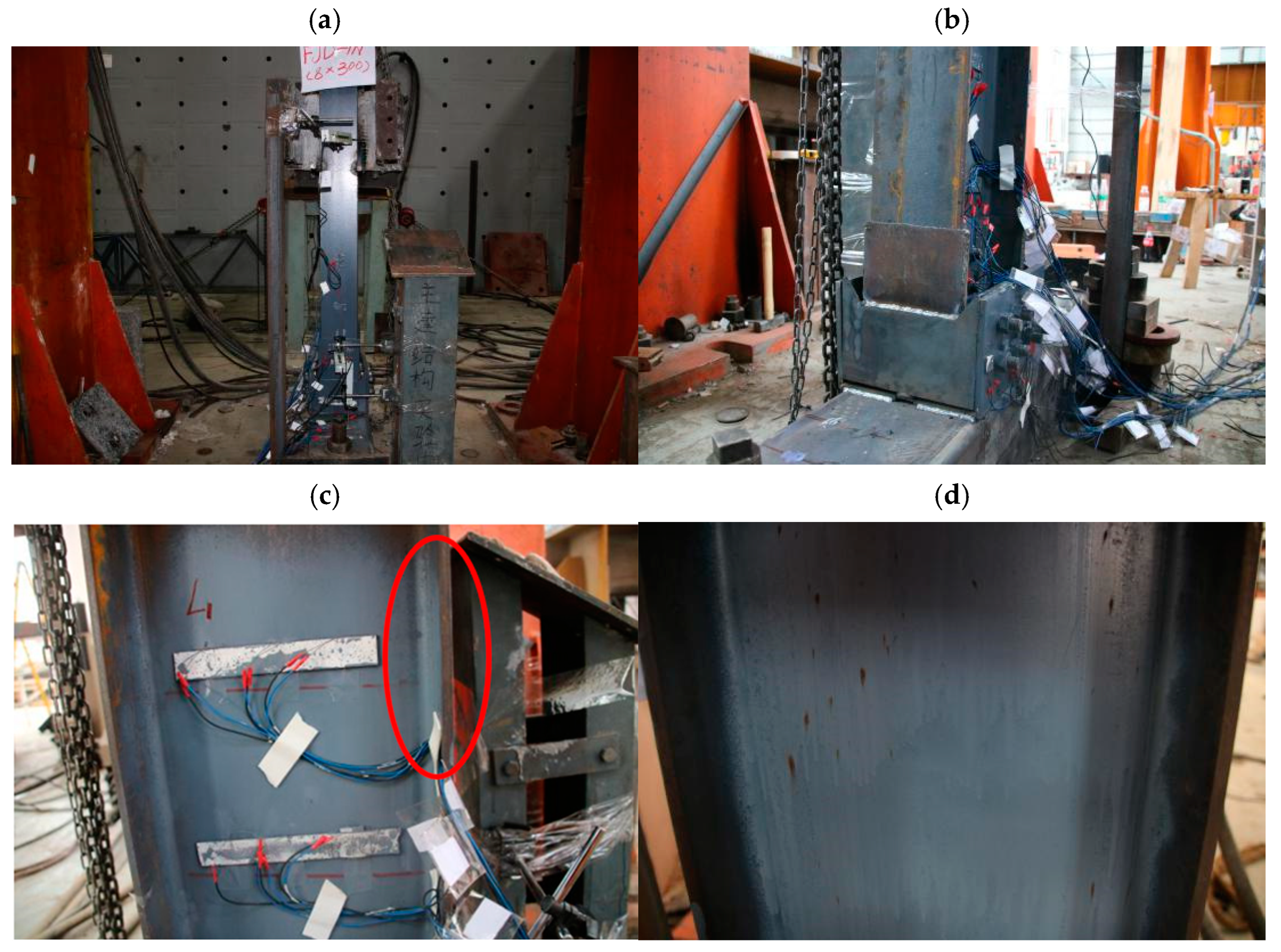
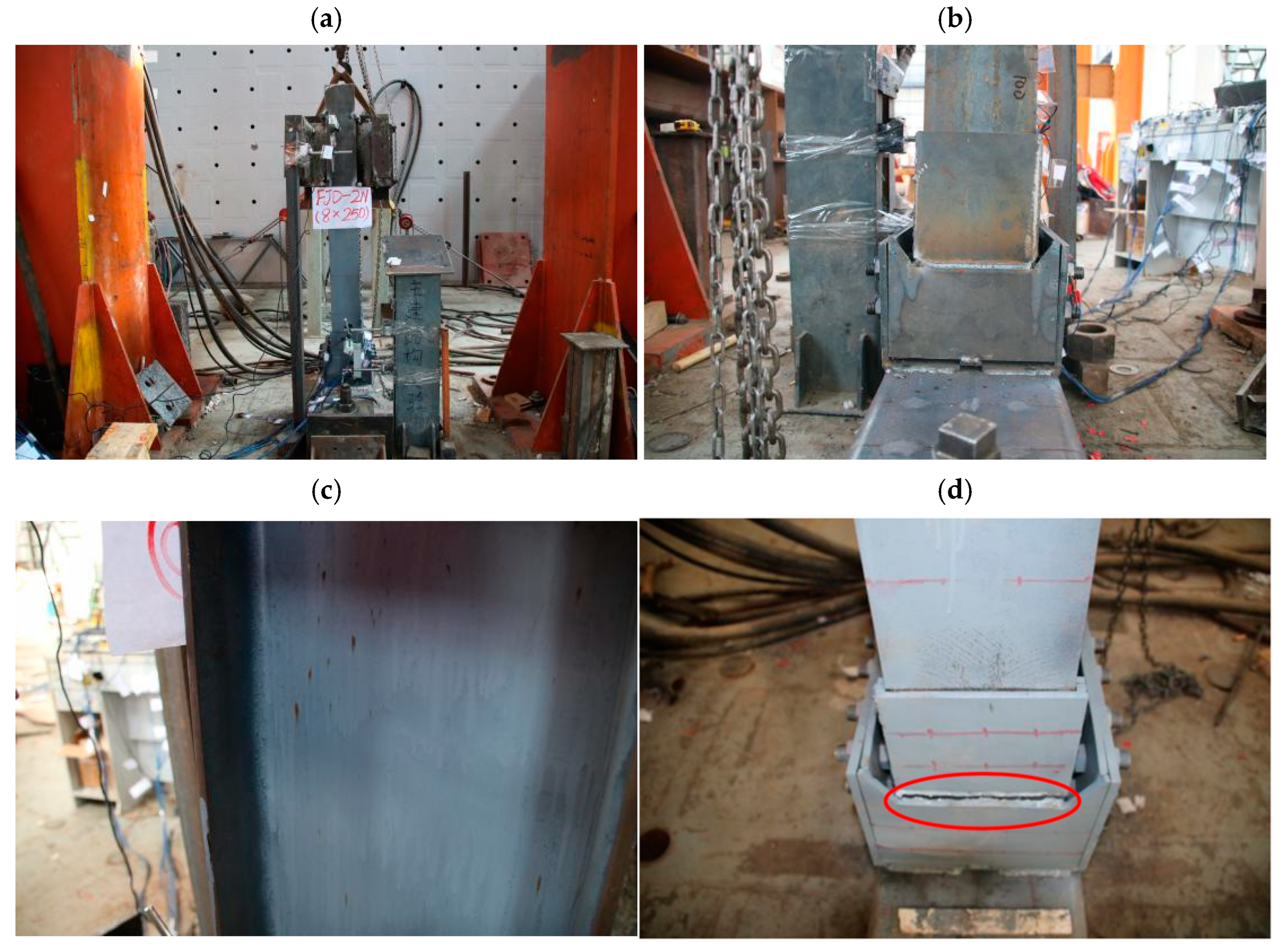
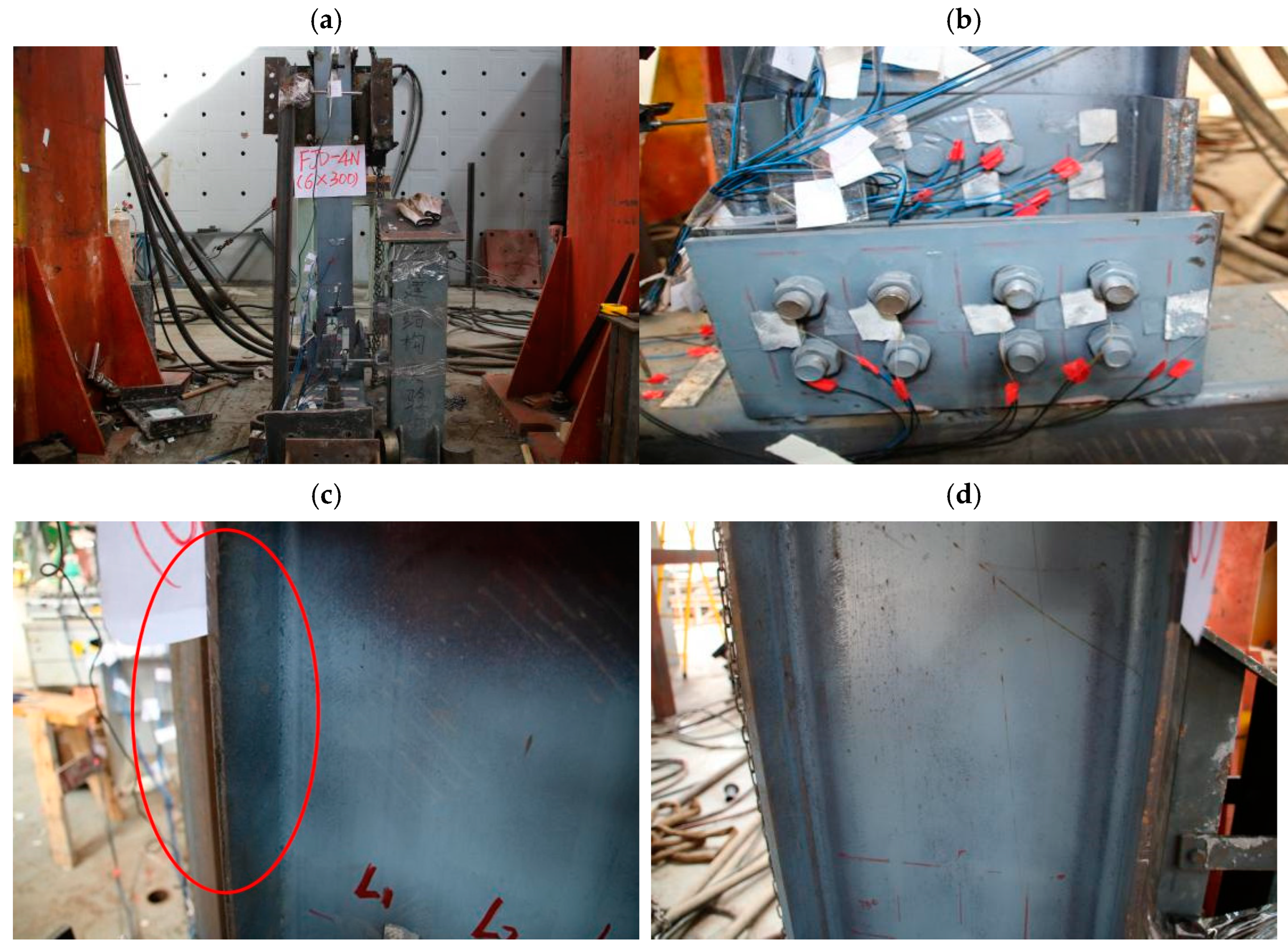
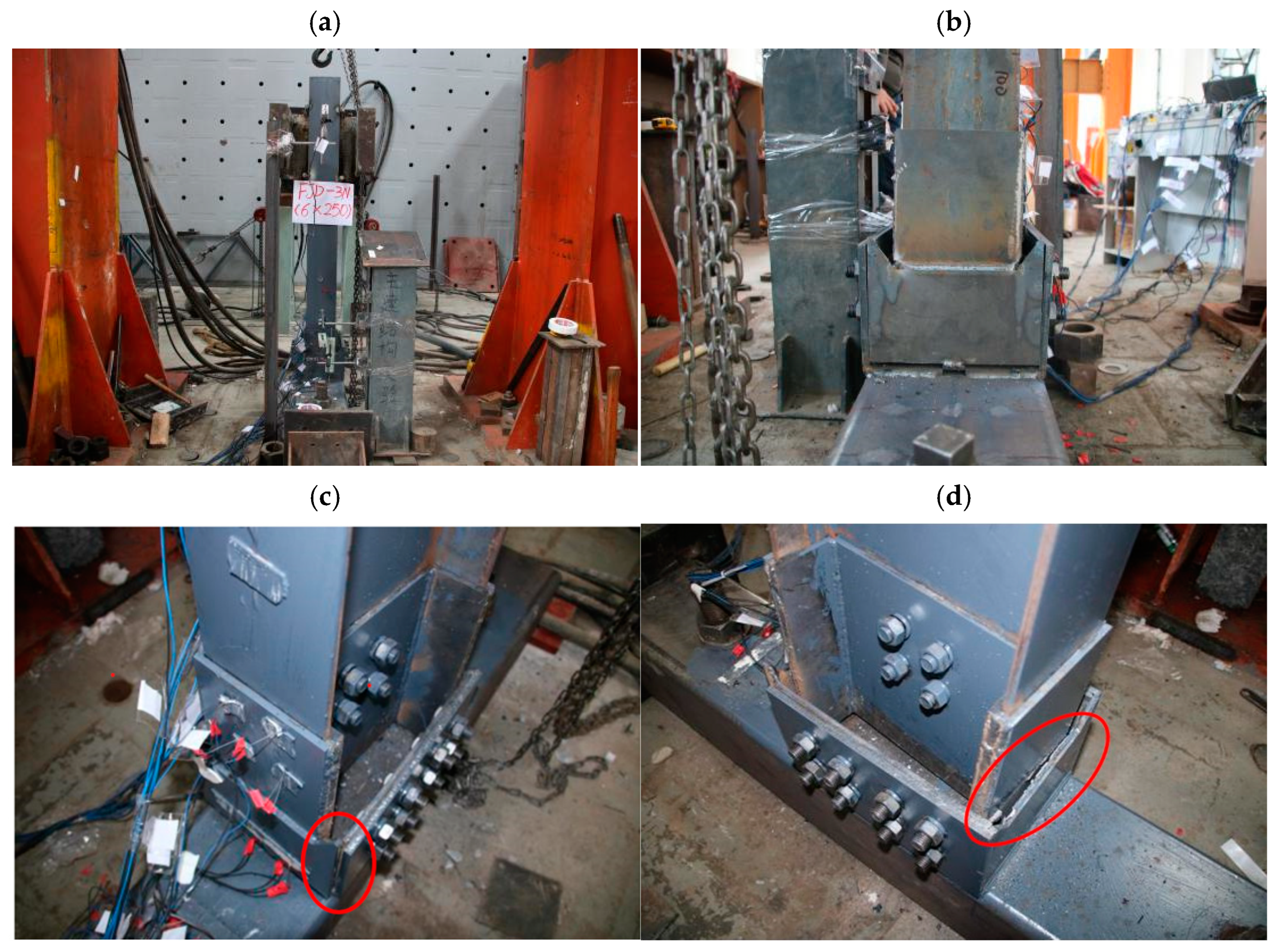
4.1. Experimental Observations

While ensuring the weld seam quality, two distinct damage modes were observed during testing of the four flange connection joints. The first mode exhibited significant plastic hinge formation at the beam end, and the second mode revealed tearing damage in the weld between the cover plate of the flange outer sleeve and the flange inner sleeve. Although the strain gages were installed in the test specimens, this analysis did not utilize the strain gauge data due to its poor quality. The suboptimal adhesion of the strain gauges likely caused significant fluctuations in the data, rendering it uninformative.
(1) FJD-1N failure mode
During the initial loading phase, the specimen showed no significant changes, and the overall force remained within the elastic range. The initial bearing force increased rapidly, accompanied by greater initial stiffness. When the load reached 28 mm, the maximum bending moment at the beam’s end was 61.65 kN·mm. At this point, a slight rotation occurred between the flange connection and the sleeve plate of the column, accompanied by a frictional sound, as shown in Figure 7b. The sound during loading resulted from friction between the beam flange and the flange inner sleeve due to discrepancies in deformation, primarily caused by the larger rotation angle of the H-beam compared to the flange connection. As the load reached 42 mm, the sound grew louder and more frequent. By 60 mm, the rotation between the flange connection and the sleeve plate of the column became more noticeable and frequent, with intense sounds, while the high-strength bolts of the column’s sleeve plate did not slip. This load caused slight bulging of the beam flange below 80 mm from the end of the beam, with some paint peeling on the web, as shown in Figure 7c,d. At 76 mm, the bulging of the beam flange became more pronounced, and it could no longer return to its original flat state, even under tension. As the reciprocal displacement increased, a plastic hinge began to form on the beam, but no significant changes were observed in the flange connection and the steel column. By 86 mm, the plastic hinge on the beam continued to develop, and the beam web gradually showed signs of bulging. At 100 mm, with a maximum bending moment of 116.52 kN·mm at the beam end, significant angular displacement occurred at the joint, prompting the cessation of loading.
(2) FJD-2N failure mode
Initially, during the first five loading cycles, the specimen remained in the elastic stress stage with no visible deformation. At 24 mm of loading, the hysteresis curve showed the steel beam beginning to yield and exhibit elastic–plastic deformation. By 32 mm, a maximum bending moment of 42.91 kN·mm occurred at the beam end, accompanied by slight rotation between the flange connection and the column’s sleeve plate, producing a frictional sound (Figure 8b). At 42 mm, the rotation between the flange connection and the column’s sleeve plate intensified, accompanied by intense sounds, yet the high-strength bolts remained secure. At 54 mm of loading, the beam flange exhibited slight bulging, with minor paint peeling on the web (Figure 8c). By 68 mm, a 5 mm crack had appeared at the weld between the flange inner sleeve and the cover plate of the flange outer sleeve, with a tendency to enlarge. At 76 mm, the weld between the flange inner sleeve and the cover plate of the flange outer sleeve failed, reducing the specimen’s bearing capacity to less than 85%, leading to termination of the loading.
(3) FJD-3N failure mode
Figure 9 illustrates the specimen’s ultimate damage mode. Initially, in the first five loading cycles, the specimen remained in the elastic stress stage. At 28 mm of loading, the hysteresis curve indicated the steel beam started yielding and exhibiting elastic–plastic deformation, yet no visible changes occurred. By 36 mm of loading, the flange connection and the column’s sleeve plate rotated noticeably, while the bolts remained secure (Figure 9b). By 44 mm, the beam flange showed slight buckling about 85 mm from the beam’s end, with loose paint observed (Figure 9c). At 52 mm, the friction sound intensified, with increased frequency. The buckling of the beam flange increased, with noticeable micro-bulging on the beam web. At 76 mm, the maximum bending moment at the beam end reached 117.28 kN·mm. Micro-bulging on the beam flange and sparse paint on the beam web became more apparent (Figure 9d). By 88 mm, the specimen’s bearing capacity dropped below 85%, resulting in the cessation of loading.
(4) FJD-4N failure mode
In the initial three loading cycles, the specimen remained in the elastic stage. At 18 mm of loading, the H-beam flange yielded. Although there were no significant changes in the specimen, a friction sound became noticeable. By 28 mm of loading, misalignment between the flange connection and the column’s sleeve plate became evident, accompanied by a louder and more frequent friction sound (Figure 10b). By 36 mm, a 2 mm crack appeared between the flange inner sleeve and the beam flange, with signs of widening (Figure 10c). At 56 mm, the beam reached a maximum bending moment of 71.5 kN·mm, accompanied by a distinctive splitting sound. The weld between the flange inner sleeve and the cover plate of the flange outer sleeve was completely torn off (Figure 10d). This damage led to the termination of loading.

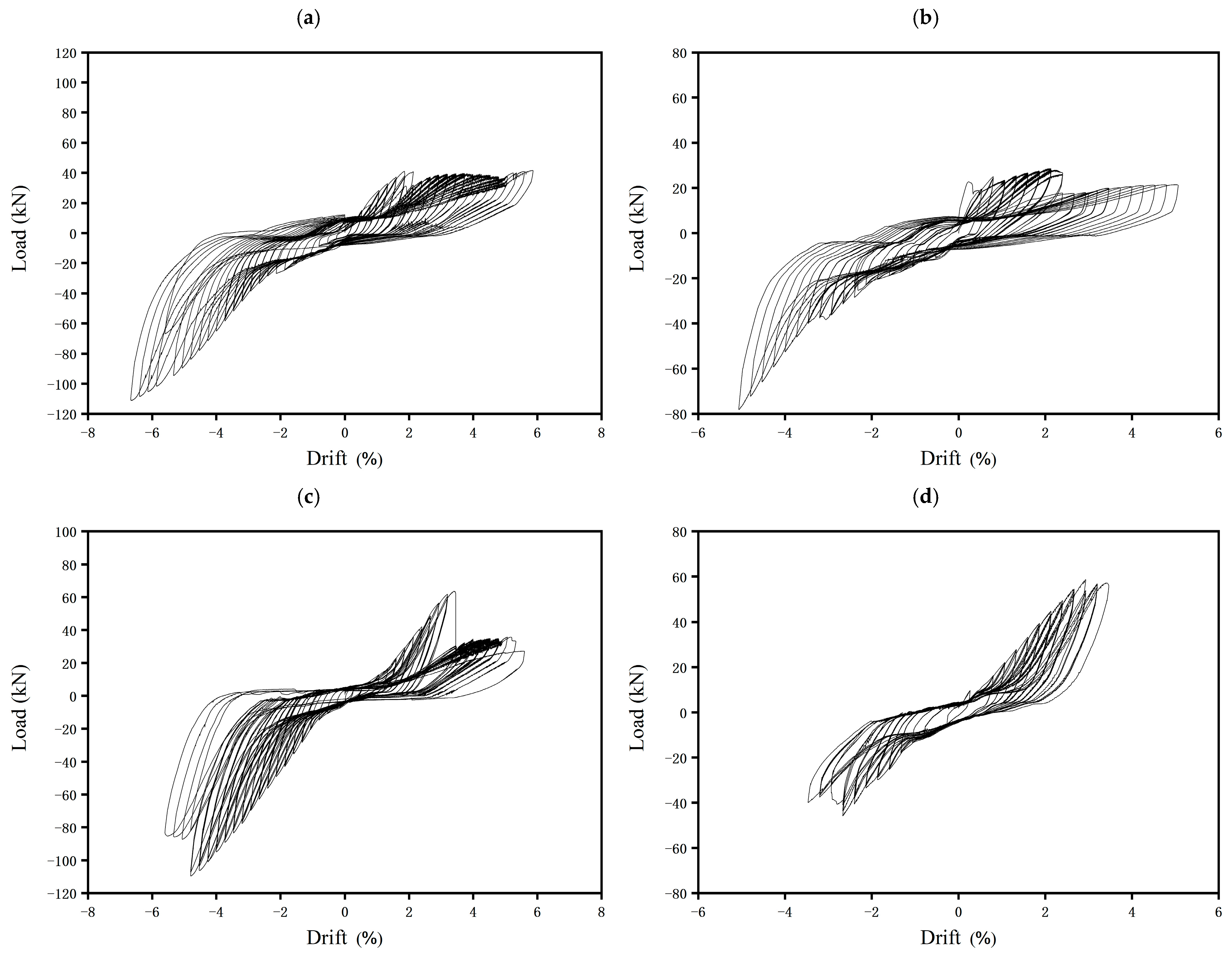
4.2. Hysteresis Behavior

Hysteresis curves for each specimen are shown in Figure 11, leading to the following conclusions: The positive and negative hysteresis curves for each specimen were asymmetrical, reflecting differences in force transmission between the flange connection joints and conventional welded joints. The asymmetry of the hysteresis curve was attributed to test errors, including construction quality issues such as welding quality, bolt preload, and loading errors. These encompassed both systematic and random errors, which resulted in the asymmetrical hysteresis curves. Horizontal loads subjected the beam’s bottom to both bending moment and shear force. During each cyclic loading level, one side of the bottom plate of the flange experienced tension or compression, while the opposite cover plate of the flange outer sleeve remained unloaded due to the high-strength bolts in the joint area. When one side of the cover plate of the flange outer sleeve underwent plastic deformation, the load-bearing capacity of the beam’s side was significantly reduced in the next cyclic loading level. This phenomenon, termed the “seesaw phenomenon”, increased the slip of the flange connection joint. The hysteresis curve exhibited an “almost bowed” shape, demonstrating the joint’s significant plastic deformation capacity and its effectiveness in absorbing seismic energy. However, the curve also exhibited some “pinching”, mainly due to flange connection rotation, resulting in high-strength bolt slippage.

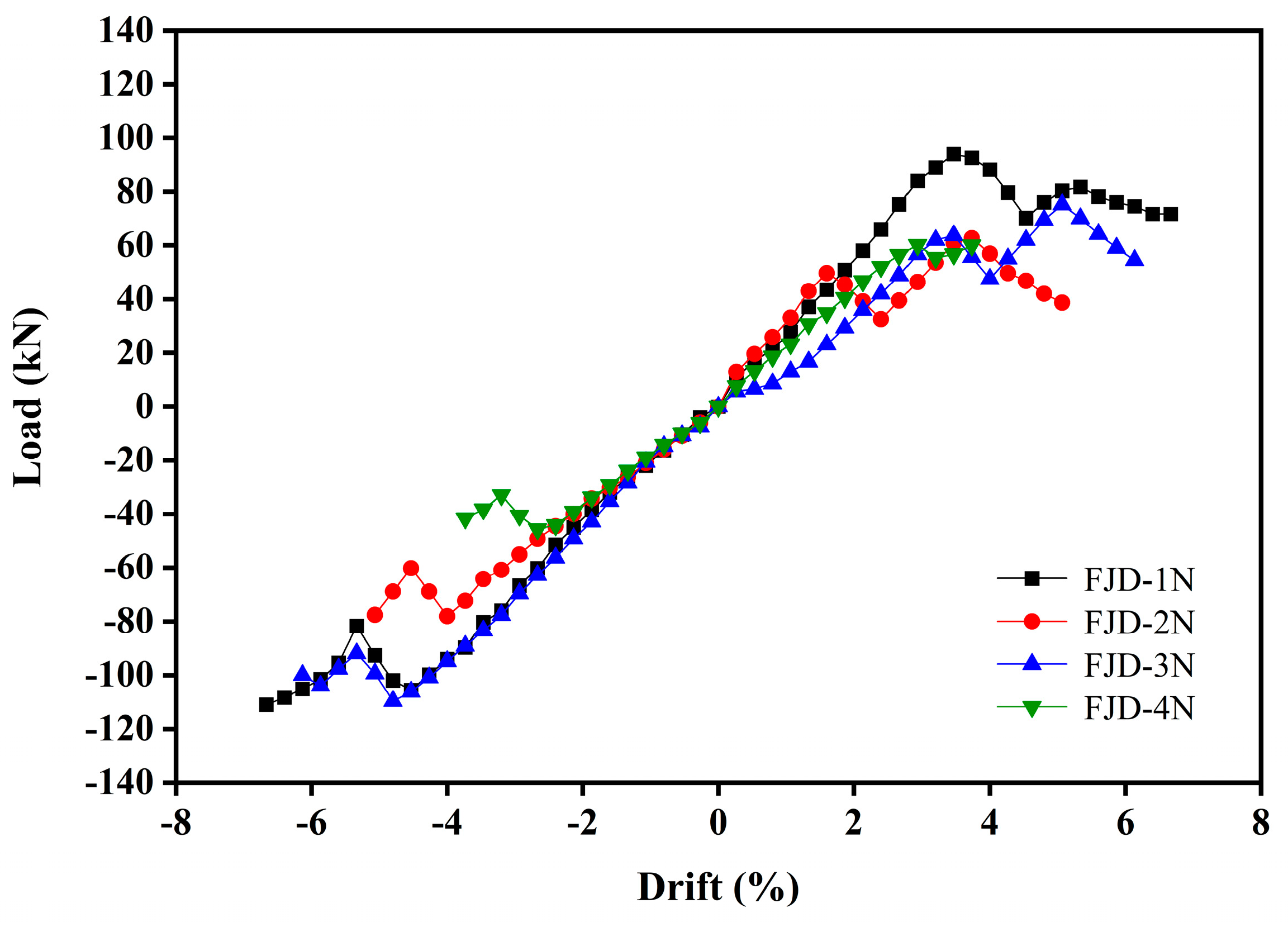
4.3. Skeleton Curves

Skeleton curves for each specimen were plotted by connecting the peak points of each control displacement, shown in Figure 12. All four sets of specimens experienced both elastic and elastoplastic phases during loading, demonstrating their significant plastic deformation capacity. Initially, the curves were generally straight and closely aligned during the elastic phase. With increasing load, some curves began to diverge, and their slopes decreased, indicating that the specimens were transitioning into the elastic–plastic deformation phase. As the load continued to increase, the curves showed a significant decrease, indicating substantial plastic deformation even after yielding. All four sets of specimens exhibited skeleton curves with a drop followed by a rebound, showing two peak points and demonstrating “secondary strengthening” of the load-bearing capacity. Under stress, two plastic hinges gradually formed in the joints. This observation confirmed that flange connection joints could exhibit “secondary reinforced” load-bearing capacity, enhancing their plastic deformation capacity.

4.4. Ductility Performance

The value of u is the displacement in which the strength decreases to 85% of the peak load, and y is obtained based on the principle of equivalent energy that was proposed by Priestley and Park [39]. Ductility is typically assessed using the ductility coefficient (μ₁), defined as the ratio of ultimate displacement to yield displacement. A higher ductility coefficient indicates a superior plastic deformation capacity, reflecting greater energy dissipation potential in a structure or member. Table 3 presents the ductility coefficients of the specimens, most of which exceeded 3.0, indicating excellent plastic deformation capabilities. The values of ductility range from 2.77 up to 3.57; this is because the test does not push for an 85% reduction in load carrying capacity, which is on the conservative side of the ductility factor. Importantly, the yield displacement of FJD-1N and FJD-3N (300 mm length) exceeded that of FJD-2N and FJD-4N (250 mm length). This observation underscores the significant influence of the length of the plastic hinge zone, corresponding to the flange inner sleeve’s length. Moreover, FJD-1N exhibited a higher ductility coefficient than FJD-2N, and FJD-3N showed a higher ductility coefficient than FJD-4N. This indicates that increasing the flange inner sleeve’s length enhances the joint’s ductility performance, assuming a consistent flange inner sleeve thickness.

4.5. Energy Consumption Capacity

Figure 13 depicts the energy dissipation capacity of each specimen. Initially, as loading commenced, the energy dissipation capacity of all four specimen groups increased proportionally with the load, following a linear growth rate. However, at 32 mm of loading, the energy dissipation curves began to diverge. Specifically, FJD-3N and FJD-4N maintained a consistent growth rate, whereas FJD-1N and FJD-2N exhibited a decline. This phenomenon highlighted the significant impact of the flange inner sleeve’s thickness on the energy dissipation growth rate in the joints. Moreover, for FJD-2N and FJD-4N (both 250 mm in length), the length of the flange inner sleeve significantly influenced the energy dissipation capacity of the joints. Increasing the flange length correspondingly increased the energy dissipation capacity. This reliance stems from the specimen initially using the flange joint for energy dissipation. Upon flange connection yielding, the energy dissipation capacity decreased. Thus, flange connection joints demonstrate a “secondary reinforcement” energy dissipation phenomenon, significantly enhancing their energy dissipation capacity.

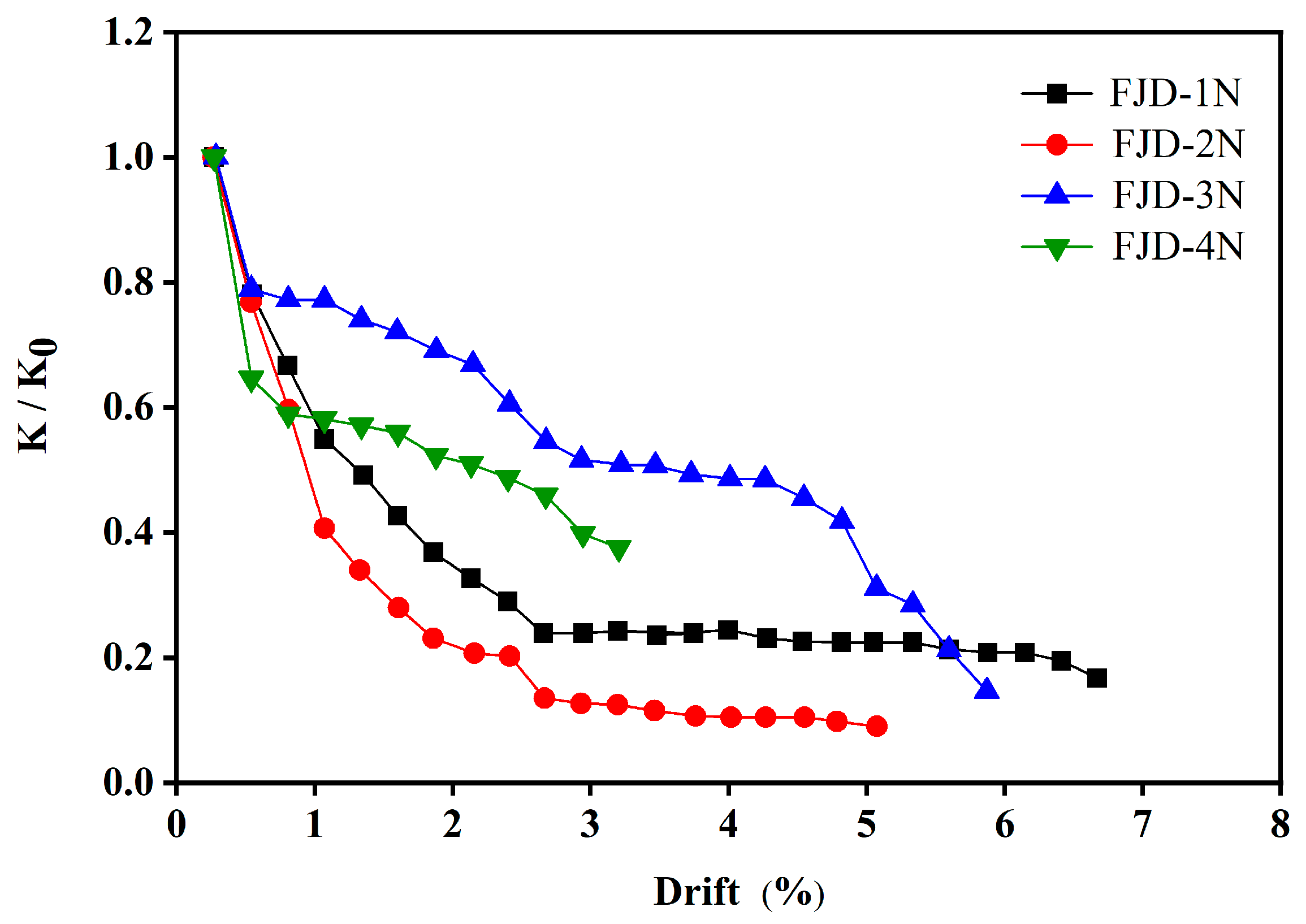
4.6. Stiffness Degradation

Stiffness degradation was quantified using the stiffness degradation coefficient, calculated from the cut-line stiffness. Figure 14 shows the stiffness degradation curves for each specimen. Cut-line stiffness at each loading displacement level was averaged from two cycles. Comparing specimens with 6 mm and 8 mm flange inner sleeve thicknesses, the 8 mm specimen showed higher initial stiffness, slower degradation, and a smoother pattern in later loading stages. Conversely, the 6 mm specimen experienced greater initial stiffness degradation after the first cycle but showed a tendency to regain stiffness with continued loading. This highlights how flange inner sleeve thickness affects initial stiffness, final degradation rate, and overall stiffness degradation trend.

5. Conclusions

The study introduces a novel joint for connecting square steel tubular columns and H-beams via a flange connection. These connection joints were comprehensively evaluated for their seismic performance through static tests and theoretical analyses, yielding the following conclusions:
(1)
The joint demonstrates robust load-bearing capacity and plastic rotation capability, facilitating effective plastic hinge formation to safeguard beam-column members from damage. After earthquakes, functionality can be restored by replacing flange connections and high-strength bolt groups.
(2)
Flange inner sleeve thickness and length significantly influence the load capacity of the joint. Thicker flange inner sleeves primarily enhance the peak load capacity and stiffness degradation resistance in the joint. Meanwhile, longer flange inner sleeves primarily enhance the ductility and energy dissipation capacity.

Author Contributions

Methodology, Y.L.; Writing—original draft, Y.C.; Project administration, T.L. All authors have read and agreed to the published version of the manuscript.

Funding

The research is supported by the National Nature Science Foundation of China (Grant No. 41472325) and Key projects of science and Technology Department of Sichuan Province (2020YJ0360).

Data Availability Statement

Data are contained within the article.

Conflicts of Interest

The authors declare no conflict of interest.

Nomenclature

SSTSquare steel tubular
HSpecimen thickness
L The length of the H-shaped steel beam
L t , w The length of the flange inner sleeve
t t , w The thickness of the flange inner sleeve
f y Yield strength
f u Ultimate strength
E Modulus of elasticity
A 0 Post-break elongation
y Yield displacement
u Ultimate displacement
μ 1 Ductility coefficient

References

  1. Fengbin, S.; Xiuli, L.; Yang, L. Research progress of prefabricated steel structure beam-column joints. Steel Constr. 2019, 34, 1–11. [Google Scholar]
  2. Ding, Y.; Deng, E.F.; Zong, L.; Dai, X.M.; Li, Y.M.; Wang, H.P.; Bi, J.X. State-of-the-art on connection in modular steel construction. J. Build. Struct. 2019, 40, 33–40. [Google Scholar]
  3. Nakashima, M.; Inoue, K.; Tada, M. Classification of damage to steel buildings observed in the 1995 Hyogoken-Nanbu earthquake. Eng. Struct. 1998, 20, 271–281. [Google Scholar] [CrossRef]
  4. Popov, E.P.; Yang, T.; Chang, S. Design of steel MRF connections before and after 1994 Northridge earthquake. Eng. Struct. 1998, 20, 1030–1038. [Google Scholar] [CrossRef]
  5. Waqas, R.; Uy, B.; Thai, H.T. Experimental and numeri-cal behaviour of blind bolted flush endplate composite connections. J. Constr. Steel Res. 2019, 153, 179–195. [Google Scholar] [CrossRef]
  6. Nuñez, E.; Torres, R.; Herrera, R. Seismic performance of moment connections insteel moment frames with HSS columns. Steel Compos. Struct. 2017, 25, 271–286. [Google Scholar]
  7. Nuñez, E.; Lichtemberg, R.; Herrera, R. Cyclic Performance of End-Plate Biaxial G. Moment Connection with HSS Columns. Metals 2020, 10, 1556. [Google Scholar] [CrossRef]
  8. Gallegos, M.; Nuñez, E.; Herrera, R. Numerical study on cyclic response of end-plate biaxial moment connection in box columns. Metals 2020, 10, 523. [Google Scholar] [CrossRef]
  9. Maali, M. Failure modes of end-plate connections with outer flange stiffeners: An experimental and numerical study. Sadhana Acad. Proc. Eng. Sci. 2020, 45, 18. [Google Scholar] [CrossRef]
  10. Ma, H.; Huang, Z.; Song, X.; Ling, Y. A Study on Mechanical Performance of an Innovative Modular Steel Building Connection with Cross-Shaped Plug-In Connector. Buildings 2023, 13, 2382. [Google Scholar] [CrossRef]
  11. Zhang, Z.; Wang, H.; Qian, H.; Gao, K.; An, B.; Fan, F. Design and Mechanical Performance Analysis of a New Type of Column-Column-Beam Prefabricated Steel Frame Joint. Struct. Eng. Int. 2021, 31, 418–426. [Google Scholar] [CrossRef]
  12. Yang, C.; Chen, H.; Ou, J. Experimental study on seismic performance of modular steel construction beam-to-beam combined side column joint with blind bolted connection. Thin-Walled Struct. 2023, 184, 110431. [Google Scholar] [CrossRef]
  13. Li, G.; Duan, L.; Lu, Y.; Zhang, L. Experimental and theoretical study of bearing capacity for extended endplate connections between rectangular tubular columns and H-shaped beams with single direction bolts. J. Build. Struct. 2015, 36, 91–100. [Google Scholar]
  14. Guoqiang, L.; Lian, D.; Ye, L.; Long, Z.; Yun, H.J. Bearing Capacity for Flush End-plated Connections Between Rectangular Tubular Columns and H-shaped Beams with Single Direction Bolts. J. Tongji Univ. (Nat. Sci.) 2018, 46, 162–169. [Google Scholar]
  15. Guoqiang, L.; Lian, D.; Ye, L.; Jie, H.Z. Initial Rotational Stiffness of H-shaped Beams to RHS Column End-plate Connections Using Blind Bolts. J. Tongji Univ. (Nat. Sci.) 2018, 46, 565–573. [Google Scholar]
  16. Zhang, A.L.; Wang, Q.; Jiang, Z.Q.; Yang, X.F.; Zhang, H. Experimental study of earthquake-resilient prefabricated steel beam-column joints with different connection forms. Eng. Struct. 2019, 187, 299–313. [Google Scholar] [CrossRef]
  17. Zhang, A.; Xie, Z.; Zhang, Y.; Lin, H. Shaking table test of a prefabricated steel frame structure with all-bolted connections. Eng. Struct. 2021, 248, 113273. [Google Scholar]
  18. Zhang, Y.X.; Huang, W.Z.; Zheng, M.Z.; Wang, Y.; Ning, G. Parametric analysis of box-section all-bolted column connection with inner sleeve. Ind. Constr. 2018, 48, 45–53. [Google Scholar]
  19. Yan, X.Z.; Meng, Y.C.; Ai, L.Z.; Wei, Z.H. Performance of box-shaped column connection achieved with core sleeve and bolts. J. Build. Struct. 2020, 41, 180–189. [Google Scholar]
  20. Yan, W.; Qiangqiang, M.; Songsen, Y. Mechanical Properties of Beam-Column Connection Joints Using Inner Sleeve Composite Bolts in Fabricated Steel Structure. J. Tianjin Univ. (Sci. Technol.) 2016, 49 (Suppl. S1), 73–79. [Google Scholar]
  21. Qiangqiang, M.; Yan, W.; Songsen, Y. Experimental Studies on Mechanical Properties of Fabricated Beam-Column Connection with Inner Sleeve Composite Bolts. J. Tianjin Univ. (Sci. Technol.) 2017, 50 (Suppl. S1), 131–139. [Google Scholar]
  22. Mingwei, Z.; Yan, W.; Hui, S. Mechanical property analysis of prefabricated inner sleeve-T section beam-column joint. Steel Struct. 2015, 30, 12–17+48. [Google Scholar]
  23. Mingyang, L.I.; Yan, W.A.G.; Shushuo, J.I. Research on the mechanical properties of new plate-inner sleeve joint of steel modular frame. Steel Struct. 2018, 33, 1–5+10. [Google Scholar]
  24. Han, Q.; Liu, M.; Lu, Y. Mechanical Behavior Analysis of Cast Steel Joints Connecting H-Shaped Beam and Square Tube Column. J. Tianjin Univ. (Sci. Technol.) 2015, 48, 502–509. [Google Scholar]
  25. Han, Q.; Liu, M.; Lu, Y.; Xu, Y.; Xu, J. Experimental research on static behavior of cast steel joints for H-shaped beam and square tube column. J. Build. Struct. 2015, 36, 101–109. [Google Scholar]
  26. Liu, X.C.; Wu, X.; Wang, Y.; Cui, X. Seismic performance of bolted connection between H-section beam and SST column welded with inclined braces. J. Build. Eng. 2022, 61, 105270. [Google Scholar] [CrossRef]
  27. Liu, X.C.; Ren, X.; Zhan, X.X.; Zhang, Y.X. Mechanical property analysis of beam-to-column connection in a box-type modular prefabricated steel structure building. Ind. Constr. 2018, 48, 62–69. [Google Scholar]
  28. Liu, X.C.; Pu, S.H.; Zhang, A.L.; Zhan, X.X. Performance analysis and design of bolted connections in modularized prefabricated steel structures. J. Constr. Steel Res. 2017, 133, 360–373. [Google Scholar] [CrossRef]
  29. Liu, X.C.; Zhan, X.X.; Pu, S.H.; Zhang, A.L.; Xu, L. Seismic performance study on slipping bolted truss-to-column connections in modularized prefabricated steel structures. Eng. Struct. 2018, 163, 241–254. [Google Scholar] [CrossRef]
  30. Liu, X.C.; Yang, Z.W.; Wang, H.X.; Zhang, A.L.; Pu, S.H.; Chai, S.T.; Wu, L. Seismic performance of H-section beam to HSS column connection in prefabricated structures. J. Constr. Steel Res. 2017, 138, 1–16. [Google Scholar] [CrossRef]
  31. Zhan, X.X.; Liu, X.C.; Feng, S.; Yu, C. Seismic performance of a square HSS column to H-section beam bolted connection with double cover plate. Eng. Struct. 2021, 231, 111729. [Google Scholar] [CrossRef]
  32. ANSI/AISC 341-16; Seismic Provisions for Structural Steel Buildings. American Institute of Steel Construction: Chicago, CA, USA, 2016.
  33. GB 50011-2010; Code for Seismic Design of Buildings. China Architecture & Building Press: Beijing, China, 2010. (In Chinese)
  34. GB 50017-2017; Standard for Design of Steel Structures. China Architecture & Building Press: Beijing, China, 2017. (In Chinese)
  35. GB/T1591-2018; High Strength Low Alloy Structural Steels. State Administration for Market Regulation of the People’s Republic of China, and Standardization Administration of the People’s Republic of China: Beijing, China, 2018. (In Chinese)
  36. JGJ82-2011; Technical Specification for High Strength Bolt Connections of Steel Structure. Ministry of Housing and Urban-Rural Development of the People’s Republic of China: Beijing, China, 2011. (In Chinese)
  37. GB/T 2975−2018; Steel and Steel Products-Location and Preparation of Samples and Test Pieces for Mechanical Testing. China Standard Press: Beijing, China, 2018. (In Chinese)
  38. GB/T, 288. 1; Metallic Materials-Tensile Testing-Part 1: Method of Test at Room Temperature. China Standards Press: Beijing, China, 2010. (In Chinese)
  39. Priestley, M.J.N.; Park, R. Strength and Ductility of Concrete Bridge Columns Under Seismic Loading. ACI Struct. J. 1987, 84, 61–76. [Google Scholar] [CrossRef]
Figure 1. Components of the joint. (a) Disassembly of the joint; (b) Assembly of the joint.
Buildings 14 02588 g001
Figure 2. Beam-column section and geometric length.
Buildings 14 02588 g002
Figure 3. Tensile test. (a) Tensile test process. (b) Specimen after tensile test.
Buildings 14 02588 g003
Figure 4. Test loading device.
Buildings 14 02588 g004
Figure 5. Loading system.
Buildings 14 02588 g005
Figure 6. Schematic diagram of test element layout. (a) Position and number of the column and sleeve plate strain gauges. (b) Position and number of the H-beam strain gauges. (c) Position and number of the Flange connection strain gauges. (d) Position and number of the displacement meter.
Buildings 14 02588 g006aBuildings 14 02588 g006b
Figure 7. Test process and damage of FJD-1N specimen. (a) Test of the FJD-1N. (b) Rotation of the flange joint. (c) Bulging of the beam flange. (d) Loose paint on the web of the beam.
Buildings 14 02588 g007
Figure 8. Test process and damage of FJD-2N specimen. (a) Test of the FJD-2N. (b) Rotation of the flange connection. (c) Loose paint on beam flange. (d) Flange jacket cover and inner sleeve weld seam is torn.
Buildings 14 02588 g008
Figure 9. Test process and damage of FJD-3N specimen. (a) Test of the FJD-3N. (b) Rotation of the flange connection. (c) Bulging of beam flange. (d) Loose paint on the web of the beam.
Buildings 14 02588 g009
Figure 10. Test process and damage of FJD-4N specimen. (a) Test of the FJD-4N. (b) Rotation of the flange connection. (c) Flange inner sleeve pulling open the gap. (d) The flange inner sleeve and cover plate of flange outer sleeve weld seam is torn.
Buildings 14 02588 g010
Figure 11. Hysteretic curve of the specimens. (a) FJD-1N. (b) FJD-2N. (c) FJD-3N. (d) FJD-4N.
Buildings 14 02588 g011
Figure 12. Skeleton curves.
Buildings 14 02588 g012
Figure 13. Energy dissipation curves.
Buildings 14 02588 g013
Figure 14. Stiffness degradation curves.
Buildings 14 02588 g014
Table 1. Number and dimensions of the specimens.
Test
Specimens
t t , w (mm) L t , w (mm)Bolt Spacing Arrangement
(mm)
Mounting
Clearance (mm)
Bolt
FJD-1N8300110-60-1102M20
FJD-2N8250110-60-1102M20
FJD-3N6300110-60-1102M20
FJD-4N6250110-60-1102M20
Table 2. Material properties of specimens.
Name of Material ComponentSpecimen Number H   ( m m ) f y   ( N / m m 2 ) f u   ( N / m m 2 ) E   ( M P a ) A 0   ( % )
Beam Wing EdgeHY6.5391.7504.620925934.77
Beam websHF9378.3533.522193836.23
Flange 1F66398.7546.620654632.23
Flange 2F88421.2581.121835736.56
SST columnZ1010357.6528.821435729.46
Flange cover plateT1010352.6519.621046926.67
Table 3. Specimen ductility coefficient.
Specimen Number u   ( m m ) y   ( m m )μ₁
FJD-1N100283.57
−100−303.33
FJD-2N72243.00
−72−262.77
FJD-3N92283.29
−92−303.07
FJD-4N56183.11
−56−202.8
Disclaimer/Publisher’s Note: The statements, opinions and data contained in all publications are solely those of the individual author(s) and contributor(s) and not of MDPI and/or the editor(s). MDPI and/or the editor(s) disclaim responsibility for any injury to people or property resulting from any ideas, methods, instructions or products referred to in the content.

