
Optimisation of Parameters and Application of Green Recyclable Precast Hollow Steel Pipe Concrete Supports

Abstract
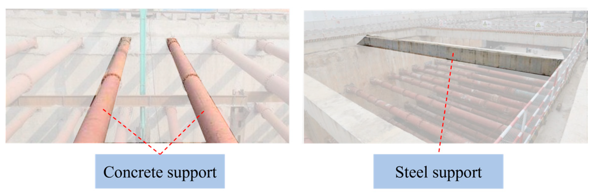
:1. Introduction
2. Design Solution for the H-CFST Support System
2.1. Nodal Connection Scheme for Prefabricated H-CFST Internal Support System
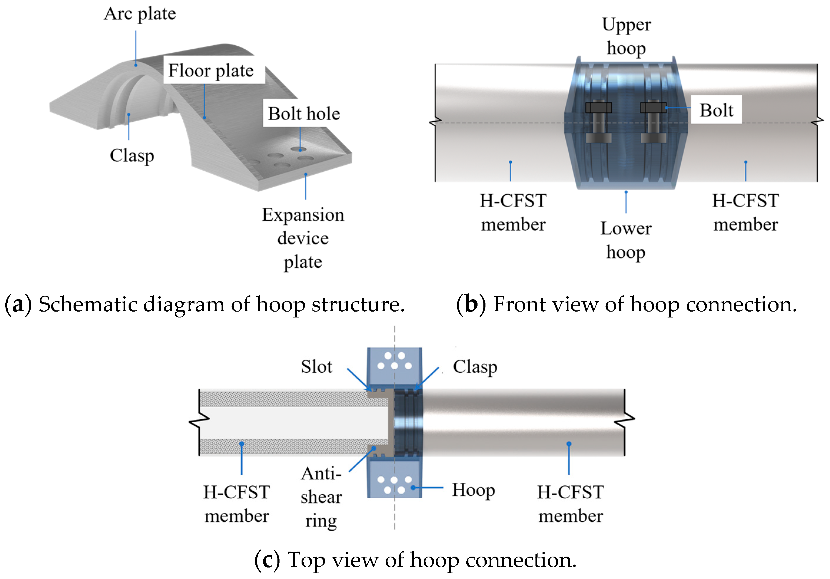
2.1.1. Intermediate Node Connectivity Programme
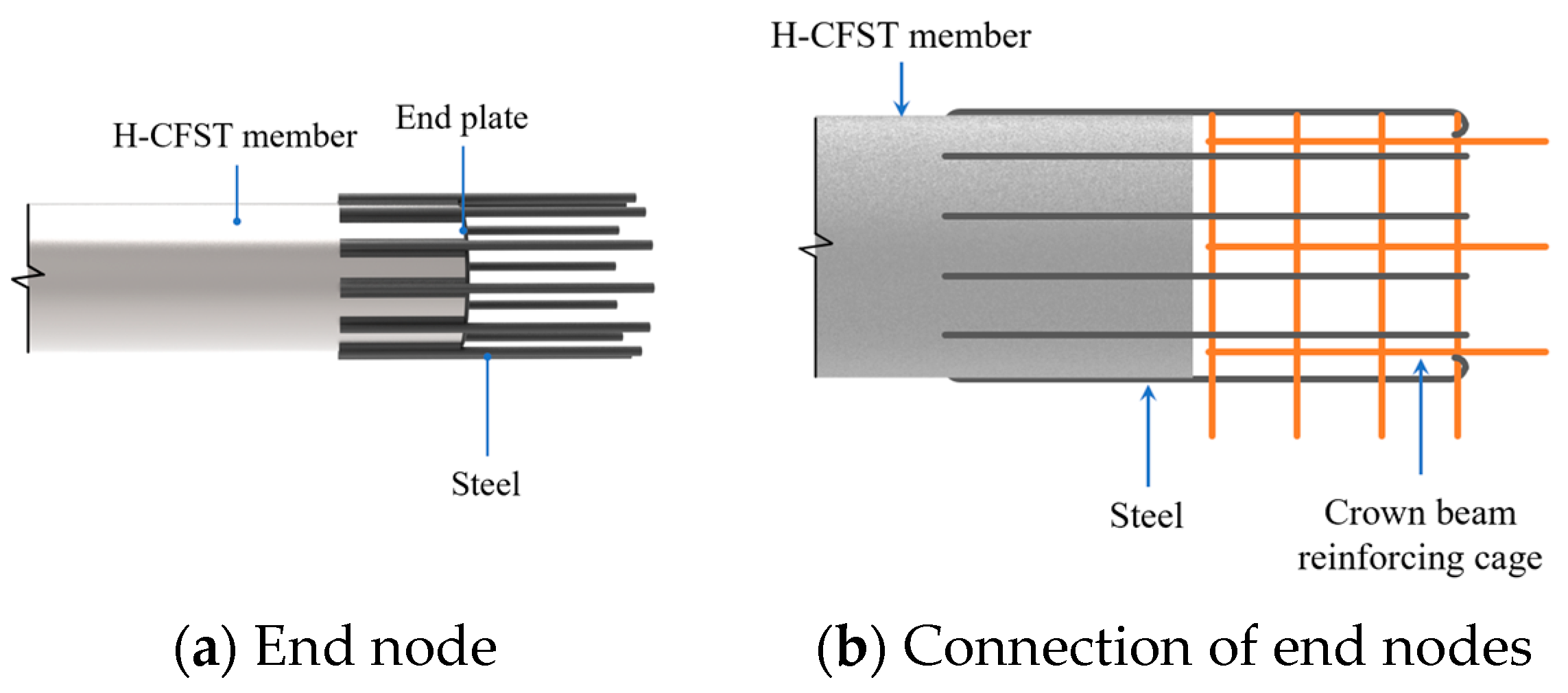
2.1.2. End Node Connectivity Programme
2.2. Prefabricated H-CFST Internal Support Elements
2.3. Axial Compressive Capacity of Hollow Steel Pipe Concrete Members
3. Parameter Optimisation of the Prefabricated H-CFST Internal Support System
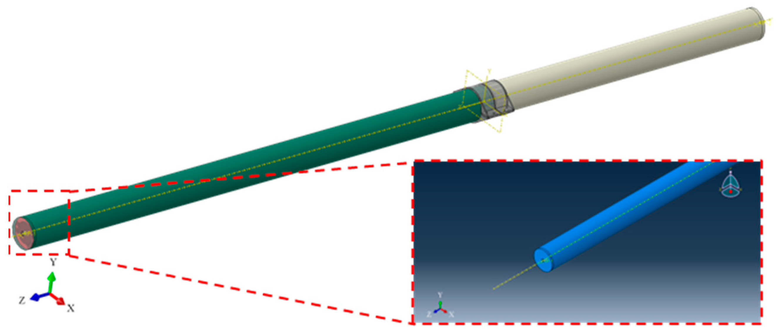
3.1. Finite Element Modelling
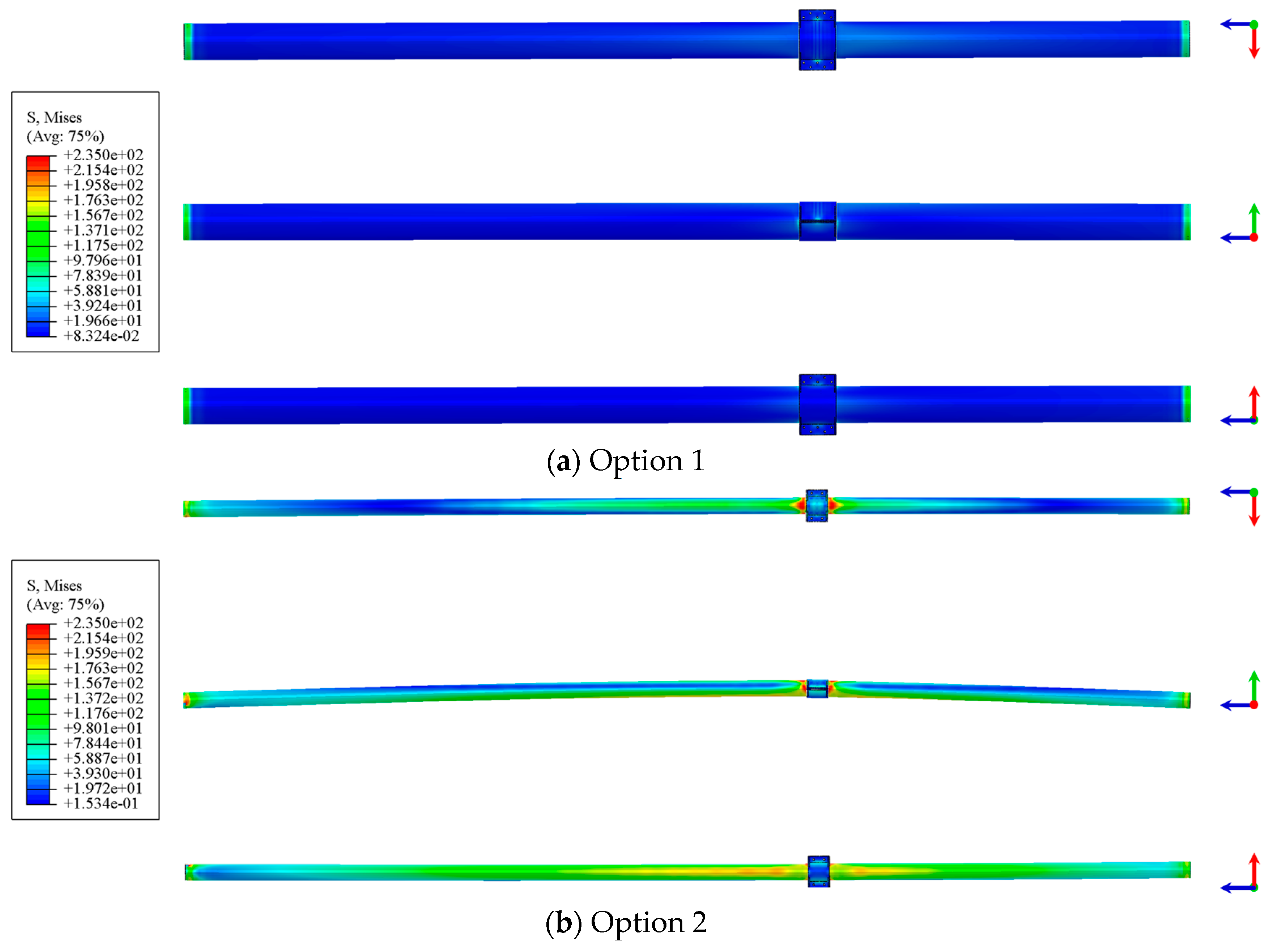
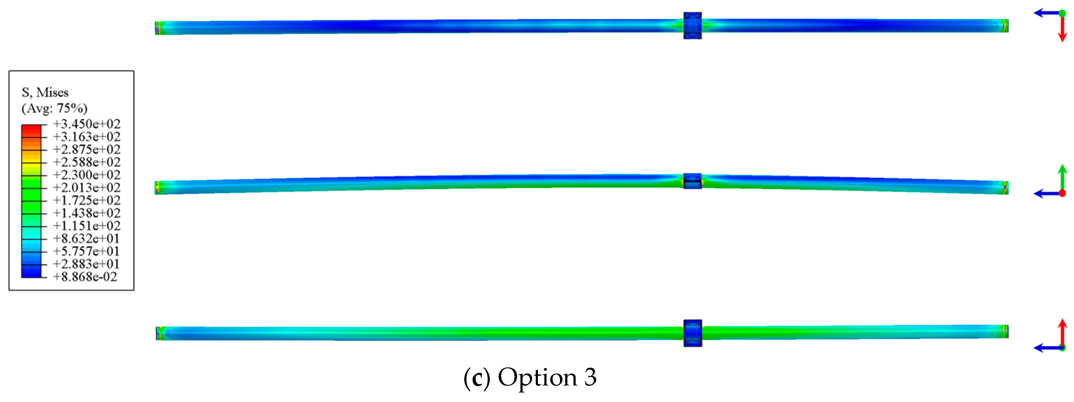
3.2. Different Aspect Ratios
3.3. Different Hollow Ratios
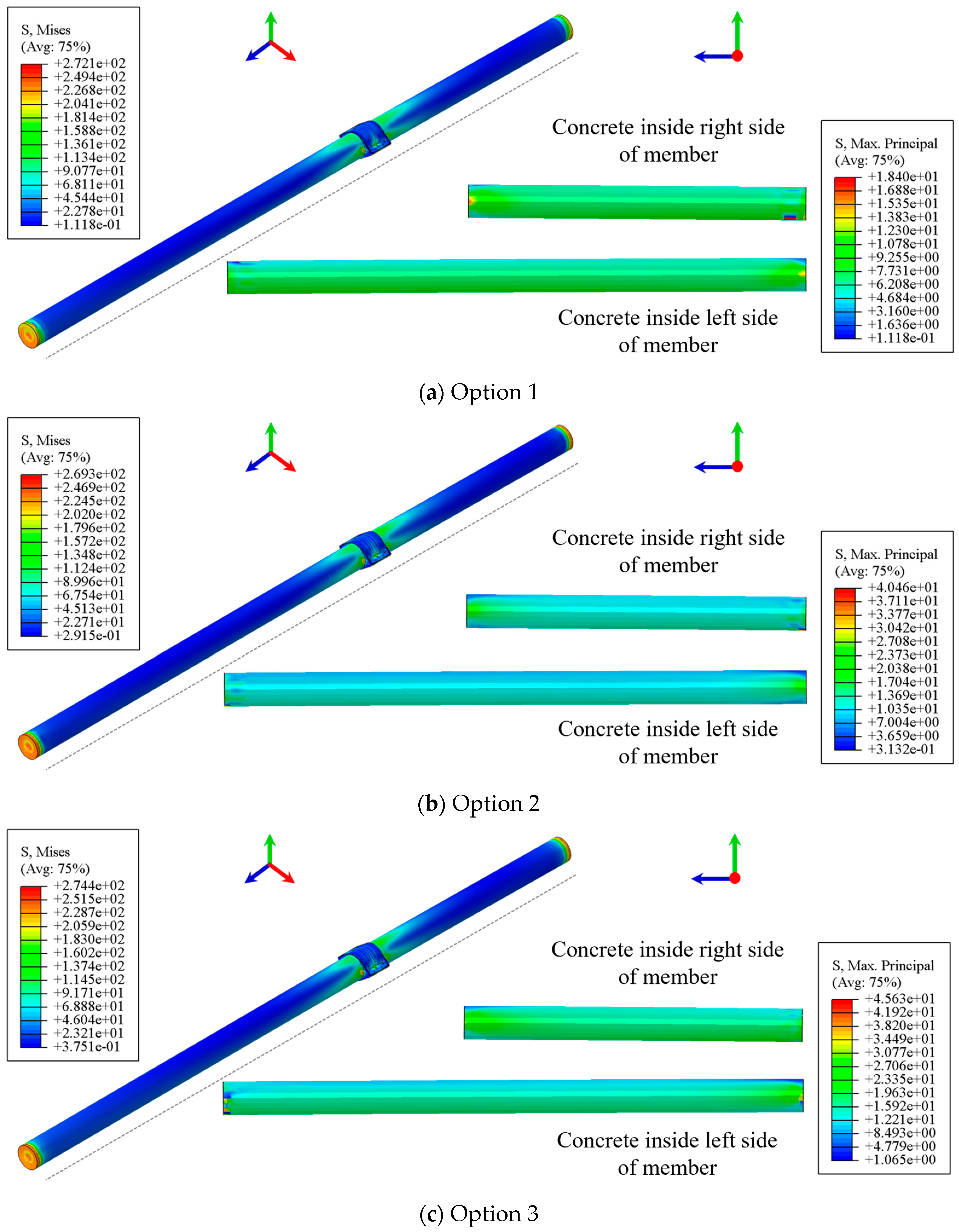
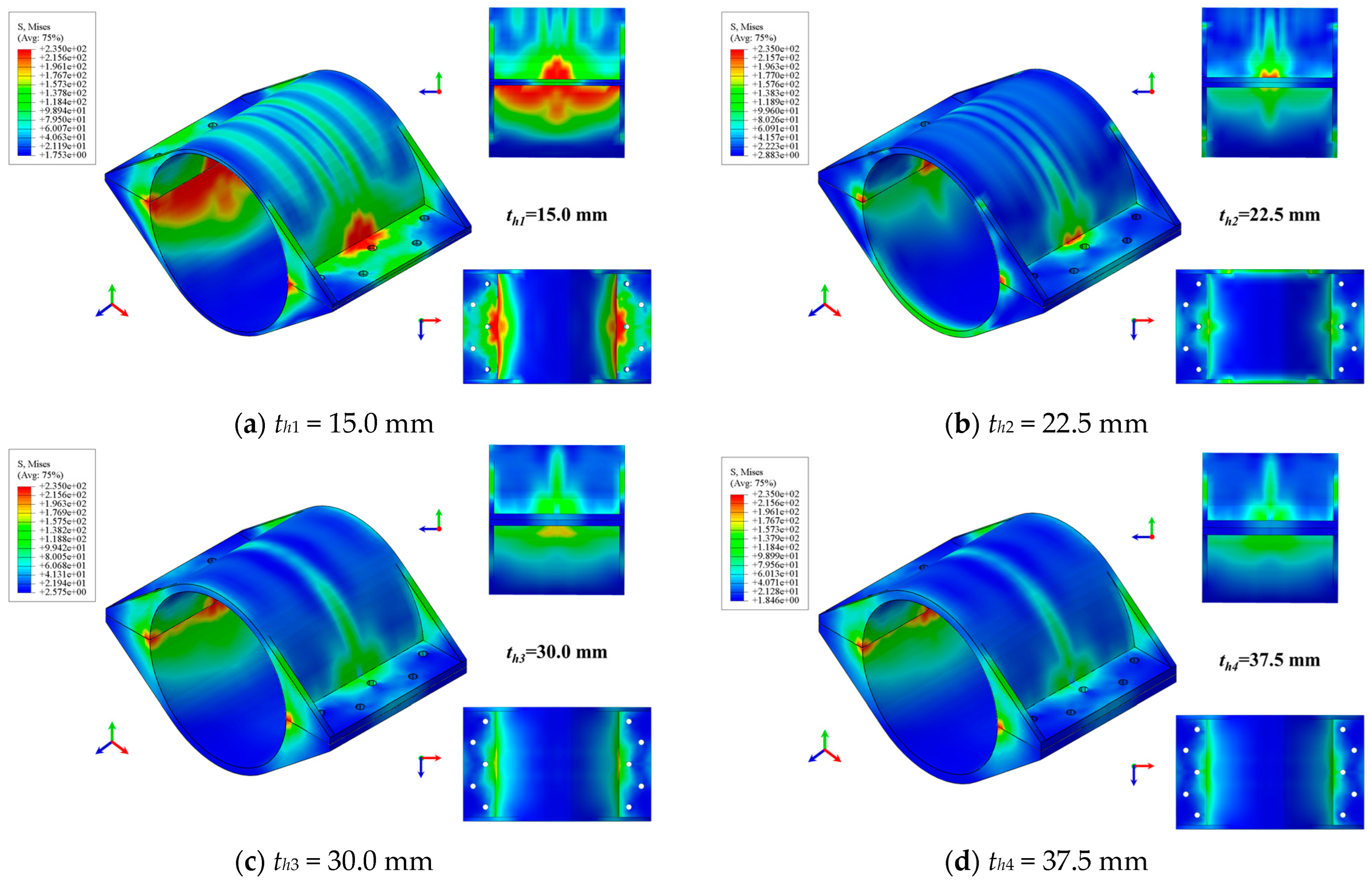
3.4. Different Hoop Thicknesses
3.5. Different Hoop Lengths
3.6. Prefabricated H-CFST Support System Design Parameters
4. Field Application Study of Prefabricated H-CFST Internal Support
4.1. Overview of Field Trials
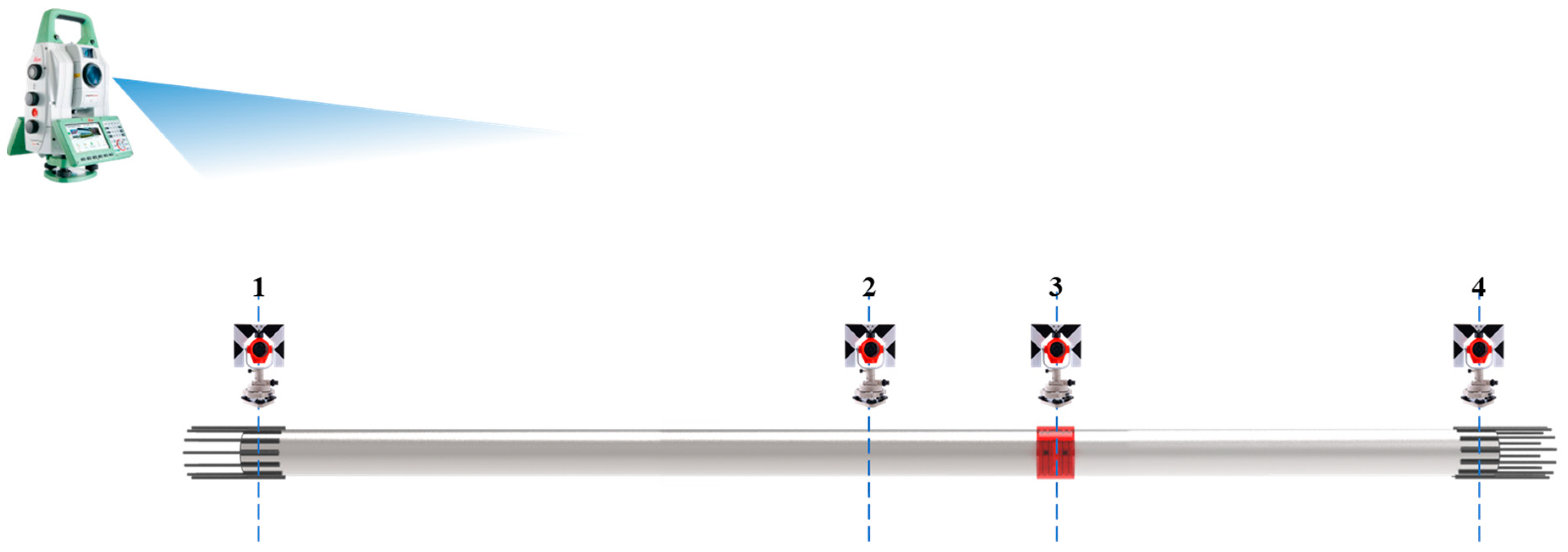
4.2. Monitoring Programme
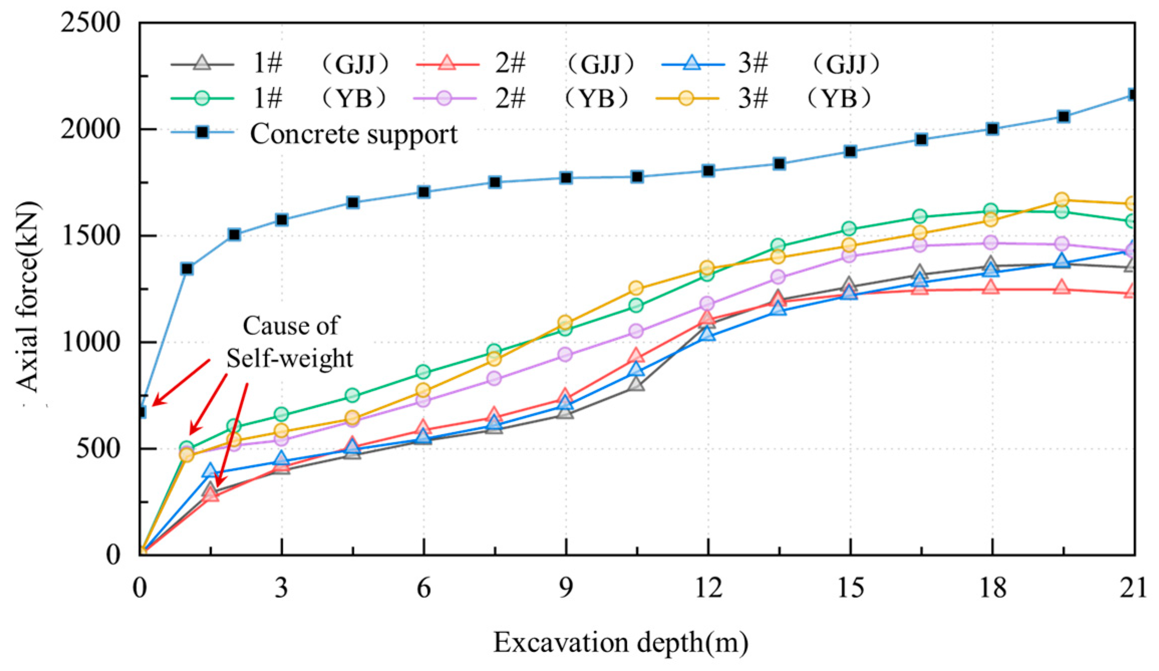
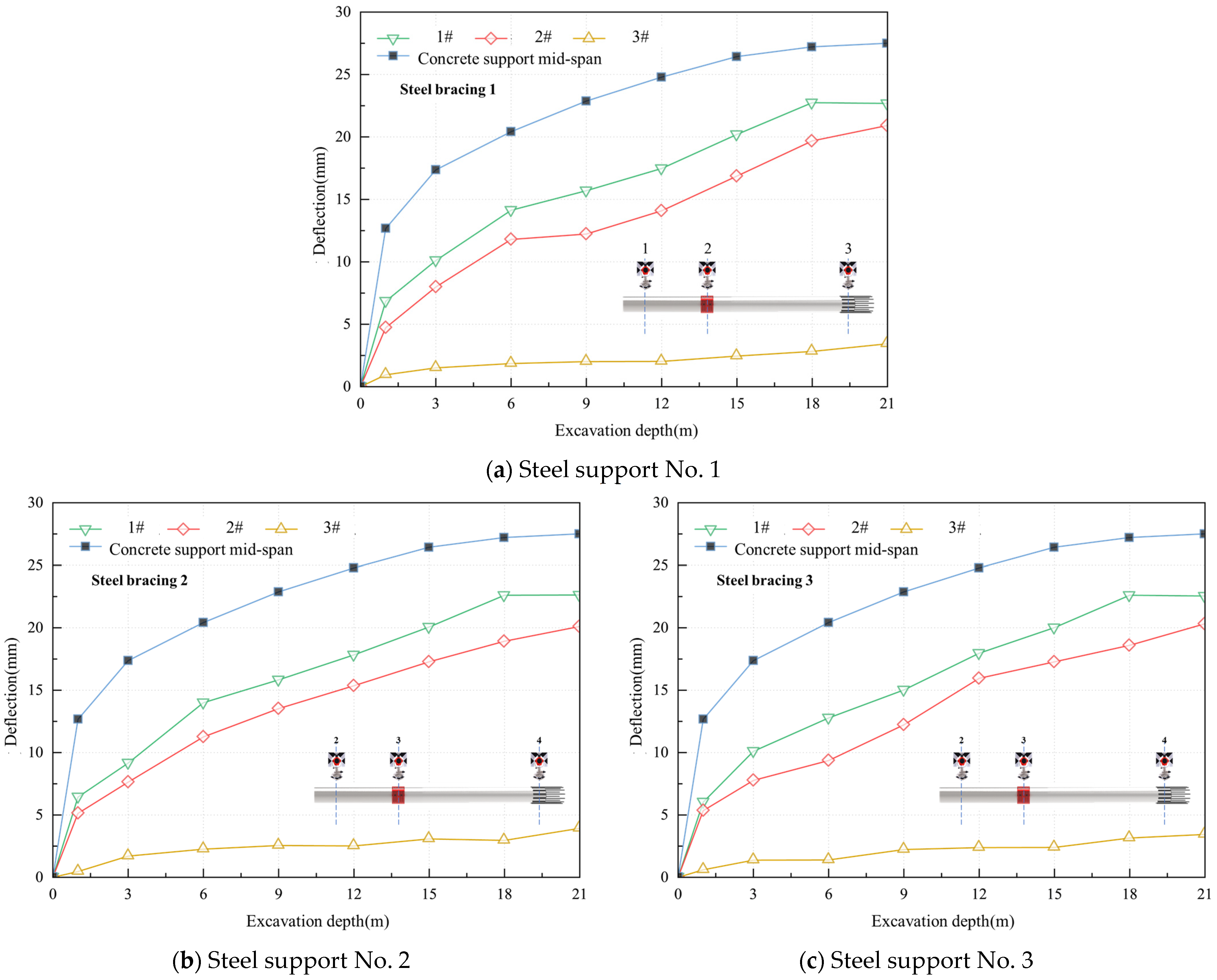
4.3. Analysis of Monitoring Results
5. Conclusions
- (1)
- We adopted the H-CFST structure to make the single pressure-bearing member of the pit internal support system and designed an intermediate node in the middle of the support span by adopting the hoop to bite the H-CFST internal support member. We also designed two end nodes by adopting the method of lapping and casting the reinforcement with the crown beam at the end of the support, which is a practical solution to take into account the transport of the product and the support of the pit.
- (2)
- The increase in the length-to-aspect ratio λ leads to stability of the support system and a rapid decrease in the damage load. The increase in the hollow ratio ψ leads to an increase in the maximum vertical displacement of the support system, and the design should try to consider choosing a plane with a “smaller hollow ratio”. After the hoop thickness th exceeds 1.5th0, its increase for the prefabricated H-CFST internal support system bearing performance enhancement is no longer obvious, so the optimal design value for the hoop thickness th is 1.5th0. The optimal design value of the hoop length lh is two times the shear ring length to avoid causing local damage to the prefabricated H-CFST internal support system.
- (3)
- After the excavation of the foundation pit, the performance of the precast H-CFST internal support is better than or comparable to that of the concrete internal support in all aspects, which can meet the requirement for replacing the concrete support.
- (4)
- In this paper, numerical simulation is used to study the optimisation of the parameters of H-CFST in order to arrive at the best parameters suitable for the present study. Currently, in the era of artificial intelligence (AI) and deep learning (DL), artificial intelligence and artificial neural network (ANN) algorithms are widely used in data research [30,31,32]. In the future, relevant databases should be established to carry out efficient optimisation studies of structural design parameters using deep learning (DL) and other methods.
Author Contributions
Funding
Data Availability Statement
Conflicts of Interest
References
- Hong, C.Y.; Zhang, J.Y.; Chen, W.B. An integrated intelligent approach for monitoring and management of a deep foundation pit in a subway station. Sensors 2022, 22, 8737. [Google Scholar] [CrossRef] [PubMed]
- Xie, Z.T.; Liu, X.; Niu, X.K.; Jian, J.L.; Xu, C.T.; Liao, J.H. Study on the Influence of the Performance Weakening of the Disconnectable Coupling (DC) Joint of Steel Support on the Retaining Structure of a Foundation Pit. Buildings 2024, 14, 1330. [Google Scholar] [CrossRef]
- Mei, R.F. Example Analysis of Steel Support and Concrete Support Effect. Master’s Thesis, Wuhan University of Engineering, Wuhan, China, 2016. [Google Scholar]
- Wang, W.; Wang, J.; Li, Q.; Xu, Z.H. Design and Performance of Large Excavations for Shanghai Hongqiao International Airport Transport Hub Using Combined Retaining Structures. J. Aerosp. Eng. 2015, 28, 6. [Google Scholar] [CrossRef]
- San, Y.H.; Zhang, M.J.; Guo, C.X.; Guo, F.; Li, P.F.; Gao, Y.H.; Liu, Y.J. The bearing performance of the assembled internal support bolts-moulded bag concrete fixed end and its bearing performance. Railw. Stand. Des. 2024, 68, 161–170. [Google Scholar] [CrossRef]
- Dai, X.; Cai, J.; Diao, Y.; Huo, H.F.; Xu, G.Y. Influence of tunnelling on the deformation of the overlying excavation bracing system and analysis of countermeasures. Comput. Geotech. 2021, 134, 104089. [Google Scholar] [CrossRef]
- Guo, X.Y.; Zhang, M.J.; Ma, D.; Huang, L.X.; Wang, W.X.; Wang, C.S.; Yang, S.P.; Qiao, J.S. An engineering case study on the adoption of P-CFST for the first internal support of foundation pit project. J. Zhejiang Univ. (Eng. Ed.) 2019, 53, 51–60. [Google Scholar]
- Guo, X.Y.; Zhang, M.J.; Wu, L.W.; Han, L.T. Application of assembled steel pipe concrete internal support in shield shaft deep foundation pit project. J. Lanzhou Univ. Technol. 2020, 46, 131–136. [Google Scholar]
- Jiang, X.H. Study on Mechanical Properties and Application of Hollow Concrete Filled Steel Tubular Braces. Master’s Thesis, Chang’an University, Xi’an, China, 2021. [Google Scholar] [CrossRef]
- Zhang, M.J.; Guo, X.Y.; Ma, D.; Huang, L.X.; Wang, W.X. Design method of assembled steel pipe concrete internal support system for foundation pit project. J. Beijing Inst. Technol. 2016, 42, 88–96. [Google Scholar]
- Zhang, M.J.; Wang, Z.T.; Ma, D.; Guo, X.Y.; Huang, L.X. PC-CFST internal support for foundation pit engineering and its design method. Constr. Technol. 2018, 47, 182–188. [Google Scholar]
- Zhang, Y.; Han, L.; Zhou, K.; Yang, S. Mechanical performance of hexagonal multi-cell concrete-filled steel tubular (CFST) stub columns under axial compression. Thin-Walled Struct. 2019, 134, 71–83. [Google Scholar] [CrossRef]
- Lu, H.; Han, L.; Zhao, X. Analytical behavior of circular concrete-filled thin-walled steel tubes subjected to bending. Thin-Walled Struct. 2009, 47, 346–358. [Google Scholar] [CrossRef]
- Han, L.; Yao, G.; Tao, Z. Performance of concrete-filled thin-walled steel tubes under pure torsion. Thin-Walled Struct. 2007, 45, 24–36. [Google Scholar] [CrossRef]
- Cai, S.H. Recent progress of steel pipe concrete structure technology in China. J. Civ. Eng. 1999, 32, 16–26. [Google Scholar]
- Han, L.; Li, W.; Bjorhovde, R. Developments and advanced applications of concrete-filled steel tubular (CFST) structures: Members. J. Constr. Steel Res. 2014, 100, 211–228. [Google Scholar] [CrossRef]
- Lu, Y.Q.; Kennedy, D.J.L. The flexural behaviour of concrete filled hollow structural section. Can. J. Civ. Eng. 1994, 21, 111–130. [Google Scholar] [CrossRef]
- Zhong, S.T.; Cha, X.X. Development of Hollow Steel Pipe Concrete Structures in China. In Proceedings of the 2009 National Steel Structure Annual Conference, Phoenix, AZ, USA, 1–4 April 2009; China Steel Structure Association: Chengdu, China, 2009. [Google Scholar]
- Wang, Q.; Xu, S.; Jiang, B.; Li, S.C.; Xiao, Y.C.; Xin, Z.X.; Liu, B.H. Research progress of confined concrete support theory and technology for underground engineering. J. China Coal Soc. 2020, 45, 2760–2776. [Google Scholar] [CrossRef]
- Gang, M.H. Study on Connection and Joints Mechanical Behavior of Precast Concrete-filled Steel Tubular Composite Components. Master’s Thesis, Northeastern University, Shenyang, China, 2021. [Google Scholar] [CrossRef]
- Gao, H.Y. Study on Connection and Joint Mechanical Behavior of Precast Reinforced Concrete-filled Steel Tubular Members. Master’s Thesis, Northeastern University, Shenyang, China, 2020. [Google Scholar] [CrossRef]
- Yang, H.; Yu, Y.J.; Kang, L.; Chen, J.F.; Luo, Y. Study on mechanical behavior of flange-connected CFST column-steel beam joint with external stiffening ring plate. J. Build. Struct. 2022, 43, 157–172. [Google Scholar] [CrossRef]
- Liu, X.C.; Wang, D.; Zhang, A.L.; Wu, X.T. Study on seismic performance of a full bolted-assembly connection for flange-connected L-shaped CFST column and H-shaped steel beam. J. Build. Struct. 2021, 42, 98–109. [Google Scholar] [CrossRef]
- Zhao, W.P.; He, Y.X.; Xu, G.Z.; Zhong, L.; Bai, X. Numerical simulation of compression bending bearing property of concrete filled steel tubular support joints. J. China Coal Soc. 2023, 1, 1–12. [Google Scholar] [CrossRef]
- Syn, H.B.; Wang, Q.; Lu, W.; Jiang, B.; Chen, H.B.; Liu, B.H. Characterisation analysis on compression bending of casing bending node of confined concrete arch. J. Min. Saf. Eng. 2019, 36, 149–157. [Google Scholar] [CrossRef]
- Yang, N.; Li, W.T.; Zhang, Y.H.; Li, D.Y.; Li, Y.C.; Wang, G.; Kong, D.S. Experimental study on compression bending property of casing joint of concrete filled steel tubular supporting arch with square section. J. China Coal Soc. 2017, 42, 1182–1192. [Google Scholar] [CrossRef]
- Uenaka, K.; Mizukoshi, M. Lightweight concrete filled steel tubular beam under bending-shear. Structures 2021, 30, 659–666. [Google Scholar] [CrossRef]
- Zhong, S.; Xu, G. Behaviors of centrifugal hollow concrete filled steel tube (H-CFST) stub columns under axial compression. J. Harbin Inst. Technol. 2006, 38, 1479–1482, 1503. [Google Scholar]
- CECS 254:2012; Technical Specification for Solid and Hollow Steel Pipe Concrete Structures. China Engineering Construction Standardisation Association: Beijing, China, 2012.
- Gaur, H.; Khidhir, B.; Manchiryal, R.K. Solution of structural mechanic’s problems by machine learning. Int. J. Hydromechatronics 2022, 5, 22–43. [Google Scholar] [CrossRef]
- Chen, J.H.; Wang, Z.R.; Liu, C.L. Lateral interaction by Laplacian-based graph smoothing for deep neural networks. CAAI Trans. Intell. Technol. 2023, 8, 1590–1607. [Google Scholar] [CrossRef]
- Liu, B.K.; Lu, W.Z. Surrogate models in machine learning for computational stochastic multi-scale modelling in composite materials design. Int. J. Hydromechatronics 2022, 5, 336–365. [Google Scholar] [CrossRef]


| Projects | Define | Sizes |
|---|---|---|
| L | Calculated span of the support system | 19.0 m |
| l | Lengths of the two H-CFST members | 7.0 m/12.0 m |
| D | Diameter of the two H-CFST members | 700.0 mm |
| lh | Length of hoop | 700.0 mm |
| T | Thickness of concrete | 100.0 mm |
| t | Wall thickness of steel pipe | 6.0 mm |
| th | Thickness of the hoop | 22.5 mm |
| rh | Radius of hollow part | 244.0 mm |
| Projects | Option 1 | Option 2 | Option 3 |
|---|---|---|---|
| C30; Q235 | C80; Q235 | C80; Q355 | |
| t | 6.0 mm | 6.0 mm | 4.0 mm |
| T | 100.0 mm | 37.5 mm | 37.5 mm |
| rh | 244.0 mm | 110.0 mm | 110.0 mm |
| D | 700.0 mm | 307.0 mm | 305.0 mm |
| ψ | ≈34% | ≈34% | ≈34% |
| λ | 27.14 | 61.89 | 62.30 |
| Materials | Modulus of Elasticity (GPa) | Tensile Strength (MPa) | Compressive Strength (MPa) | Densities (kN/m3) |
|---|---|---|---|---|
| Q235b steel | 200.0 | 375.0 | 235.0 | 78.5 |
| Q355b steel | 200.0 | 470.0 | 345.0 | 78.5 |
| C30 concrete | 30.0 | 2.01 | 20.1 | 23.9 |
| C80 concrete | 38.0 | 3.11 | 50.2 | 25.2 |
| Projects | Option 1 C30 | Option 2 C50 | Option 3 C80 |
|---|---|---|---|
| t | 6.0 mm | 6.0 mm | 6.0 mm |
| D | 700.0 mm | 700.0 mm | 700.0 mm |
| λ | 27.14 | 27.14 | 27.14 |
| T | 100.0 mm | 62.0 mm | 40.0 mm |
| rh | 244.0 mm | 282.0 mm | 304.0 mm |
| ψ | 34% | 40% | 44% |
| Parametric | Sizes | Parametric | Sizes |
|---|---|---|---|
| l | 7.0 m/12.0 m | T | 100.0 mm |
| D | 700.0 mm | t | 6.0 mm |
| lh | 700.0 mm | rh | 244.0 mm |
| th1 | 15.0 mm | th2 | 22.5 mm |
| th3 | 30.0 mm | th4 | 37.5 mm |
| Parametric | Sizes | Parametric | Sizes |
|---|---|---|---|
| l | 7.0 m/12.0 m | T | 100.0 mm |
| D | 700.0 mm | t | 6.0 mm |
| th | 22.5 mm | rh | 244.0 mm |
| lh1 | 400.0 mm | lh2 | 700.0 mm |
| lh3 | 1000.0 mm | / | / |
| H-CFSTmember: C80; Q355 | Hoop: Q355 | ||
|---|---|---|---|
| L | 19.0 m | l | 7.0 m/12.0 m |
| D | 700.0 mm | lh | 600.0 mm |
| T | 100.0 mm | th | 35.0 mm |
| t | 6.0 mm | Slot Depth | 25.0 mm |
| rh | 244.0 mm | Slot width | 25.0 mm |
| Parametric | Sizes | Parametric | Sizes |
|---|---|---|---|
| L | 19.0 m | T | 100.0 mm |
| l | 7.0 m/12.0 m | t | 6.0 mm |
| D | 700.0 mm | th | 35.0 mm |
| lh | 700.0 mm | rh | 244.0 mm |
Disclaimer/Publisher’s Note: The statements, opinions and data contained in all publications are solely those of the individual author(s) and contributor(s) and not of MDPI and/or the editor(s). MDPI and/or the editor(s) disclaim responsibility for any injury to people or property resulting from any ideas, methods, instructions or products referred to in the content. |
© 2024 by the authors. Licensee MDPI, Basel, Switzerland. This article is an open access article distributed under the terms and conditions of the Creative Commons Attribution (CC BY) license (https://creativecommons.org/licenses/by/4.0/).
Share and Cite
Pan, Y.; Du, Z.; Tian, H.; Zhao, W.; Xing, T.; Dong, Z.; Peng, H.; Zheng, J. Optimisation of Parameters and Application of Green Recyclable Precast Hollow Steel Pipe Concrete Supports. Buildings 2024, 14, 2647. https://doi.org/10.3390/buildings14092647
Pan Y, Du Z, Tian H, Zhao W, Xing T, Dong Z, Peng H, Zheng J. Optimisation of Parameters and Application of Green Recyclable Precast Hollow Steel Pipe Concrete Supports. Buildings. 2024; 14(9):2647. https://doi.org/10.3390/buildings14092647
Chicago/Turabian StylePan, Ye, Zhifeng Du, Haiguang Tian, Wenqiang Zhao, Tongju Xing, Zizhang Dong, Huadong Peng, and Jianguo Zheng. 2024. "Optimisation of Parameters and Application of Green Recyclable Precast Hollow Steel Pipe Concrete Supports" Buildings 14, no. 9: 2647. https://doi.org/10.3390/buildings14092647