
Centrifugal Model Test of Multi-Level Slope under Combined Support of Pile-Anchor and Frame-Anchor

Abstract
:1. Introduction
2. Centrifugal Model Design Fabrication
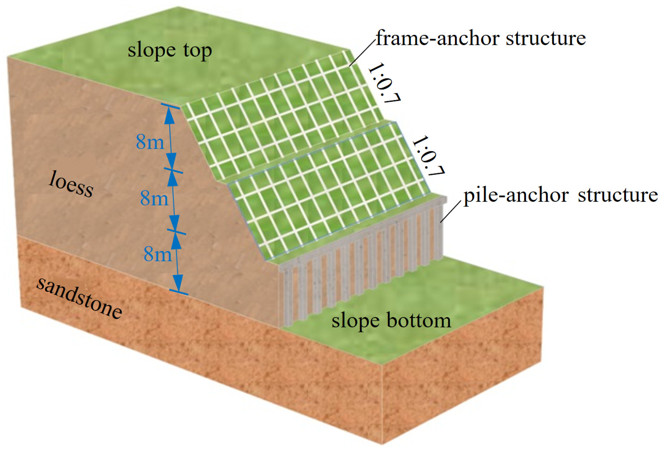
2.1. Overview of Prototype Slope
2.2. Test Equipment and Model Dimensions
- (1)
- Test equipment
- (2)
- Similarity relationship
- (3)
- Centrifugal model dimensions
2.3. Model Material Selection and Preparation
- (1)
- Model Soil Preparation
- (2)
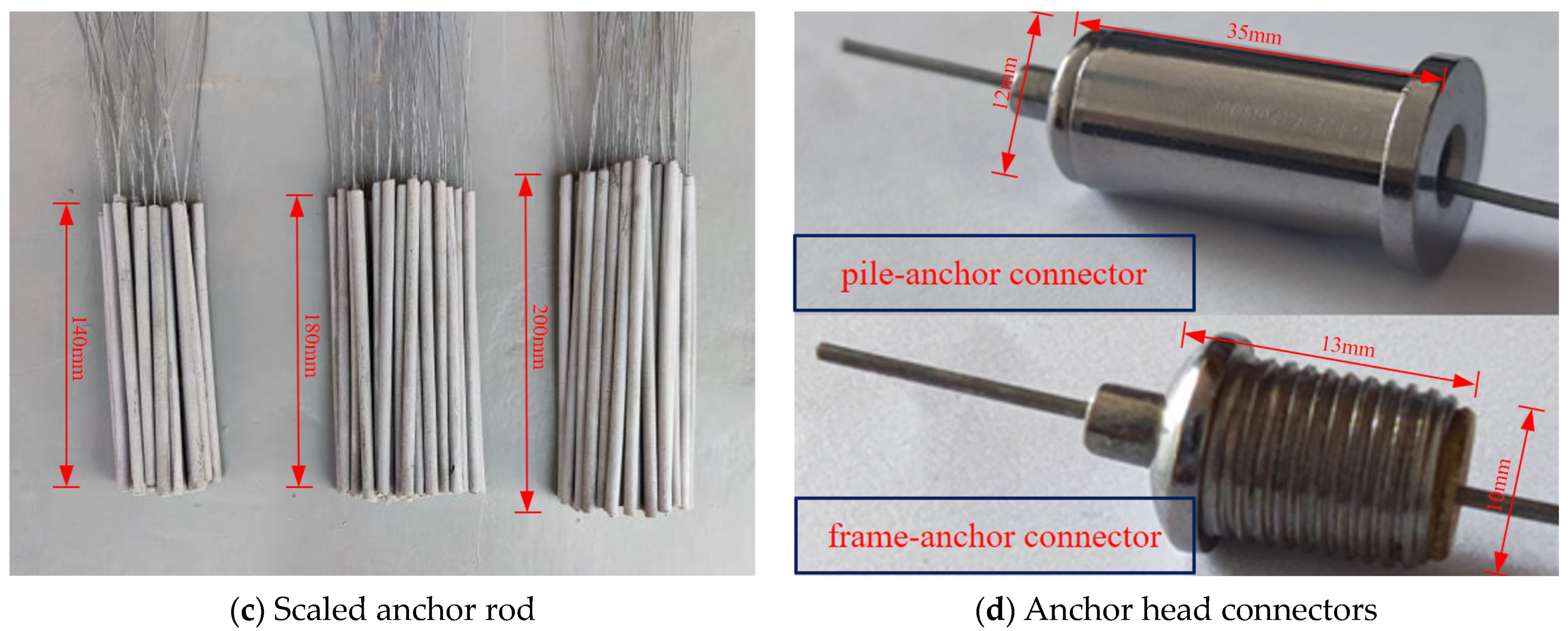
- Support Structure Fabrication
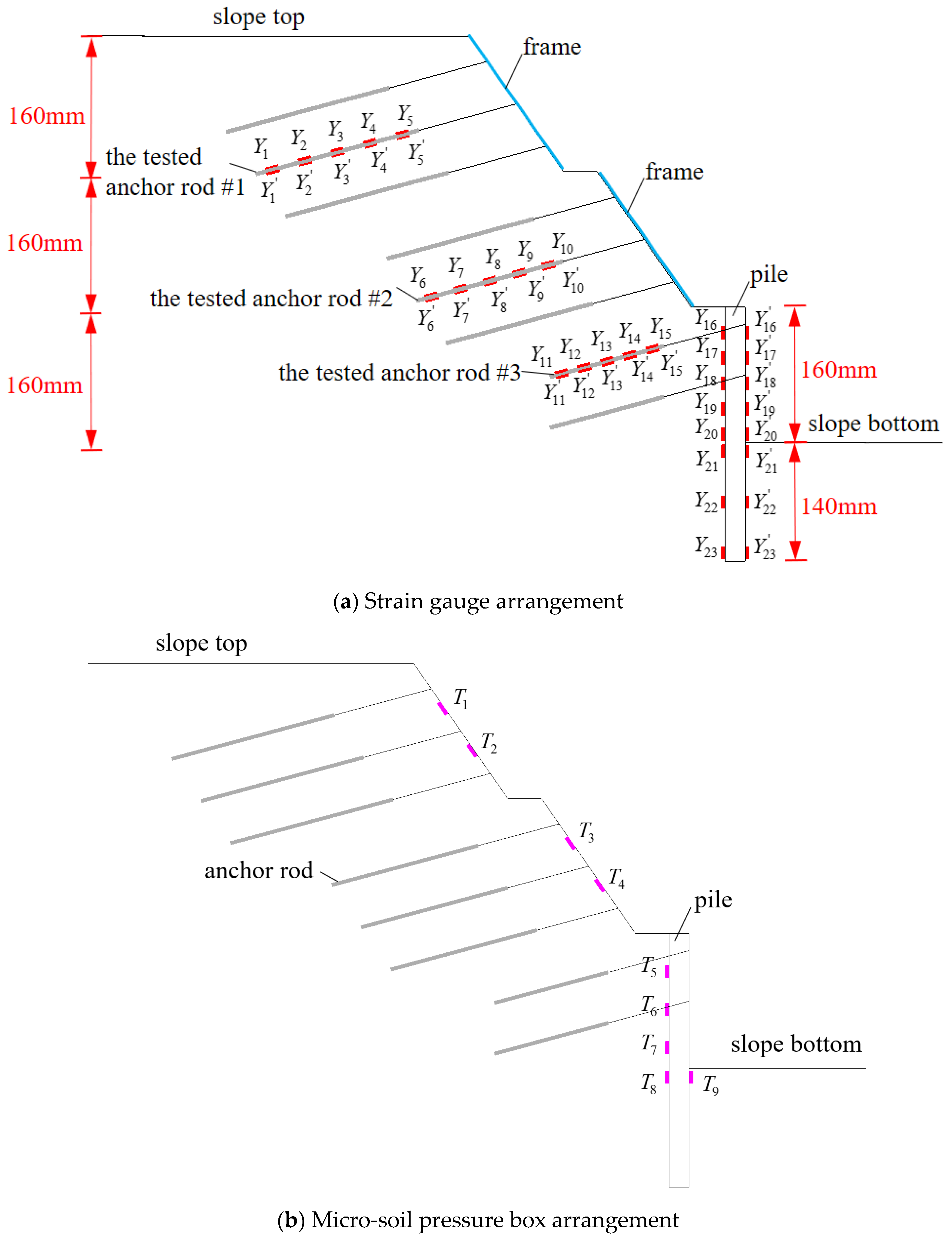
2.4. Sensor Arrangement on the Support Structure
2.5. Model Making Process
2.6. Test Loading Process
3. Centrifugal Model Test Results
3.1. Structural Force Analysis of Pile-Anchor Support Section
- (1)
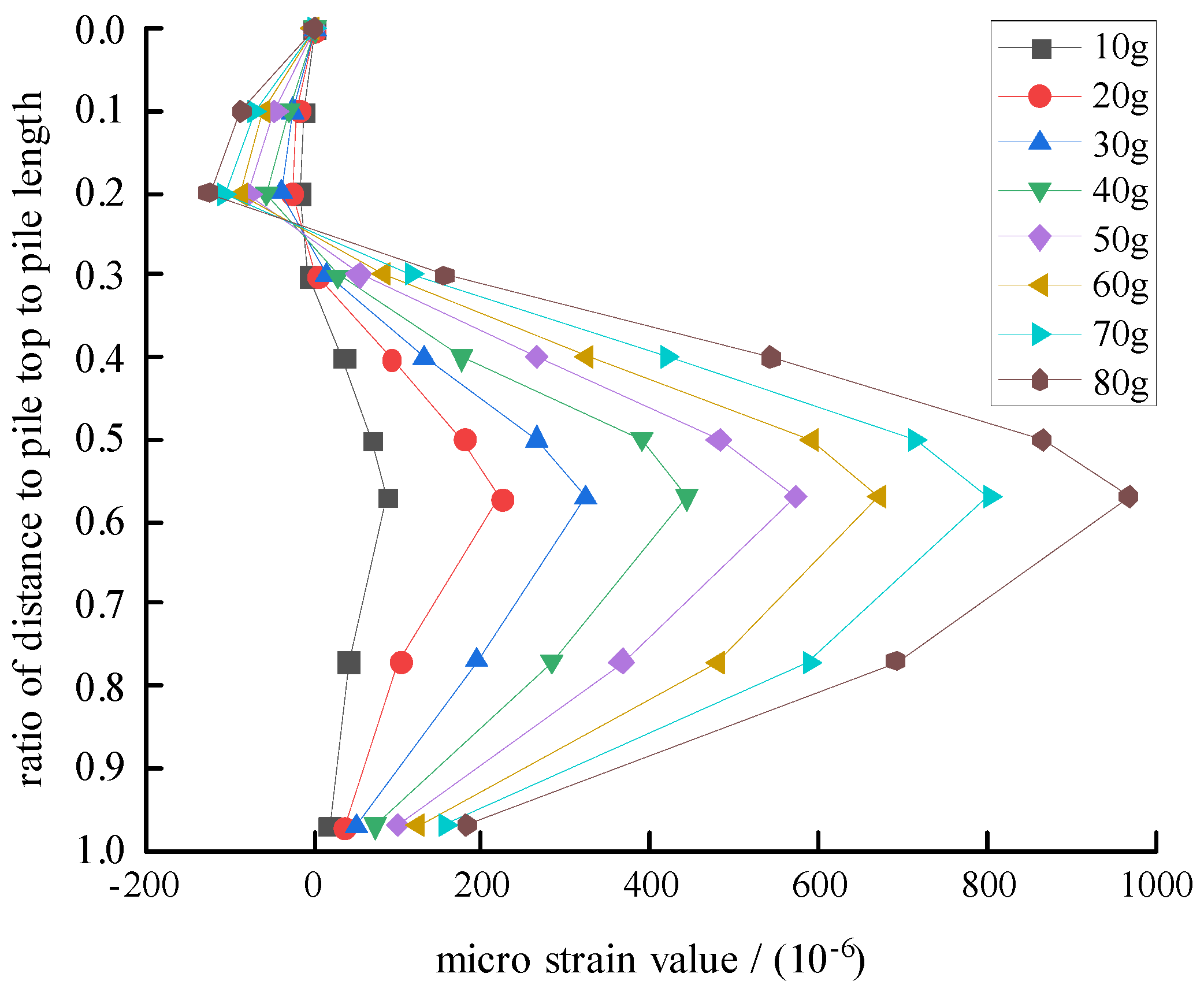
- Distribution of bending moments on piles
- (2)
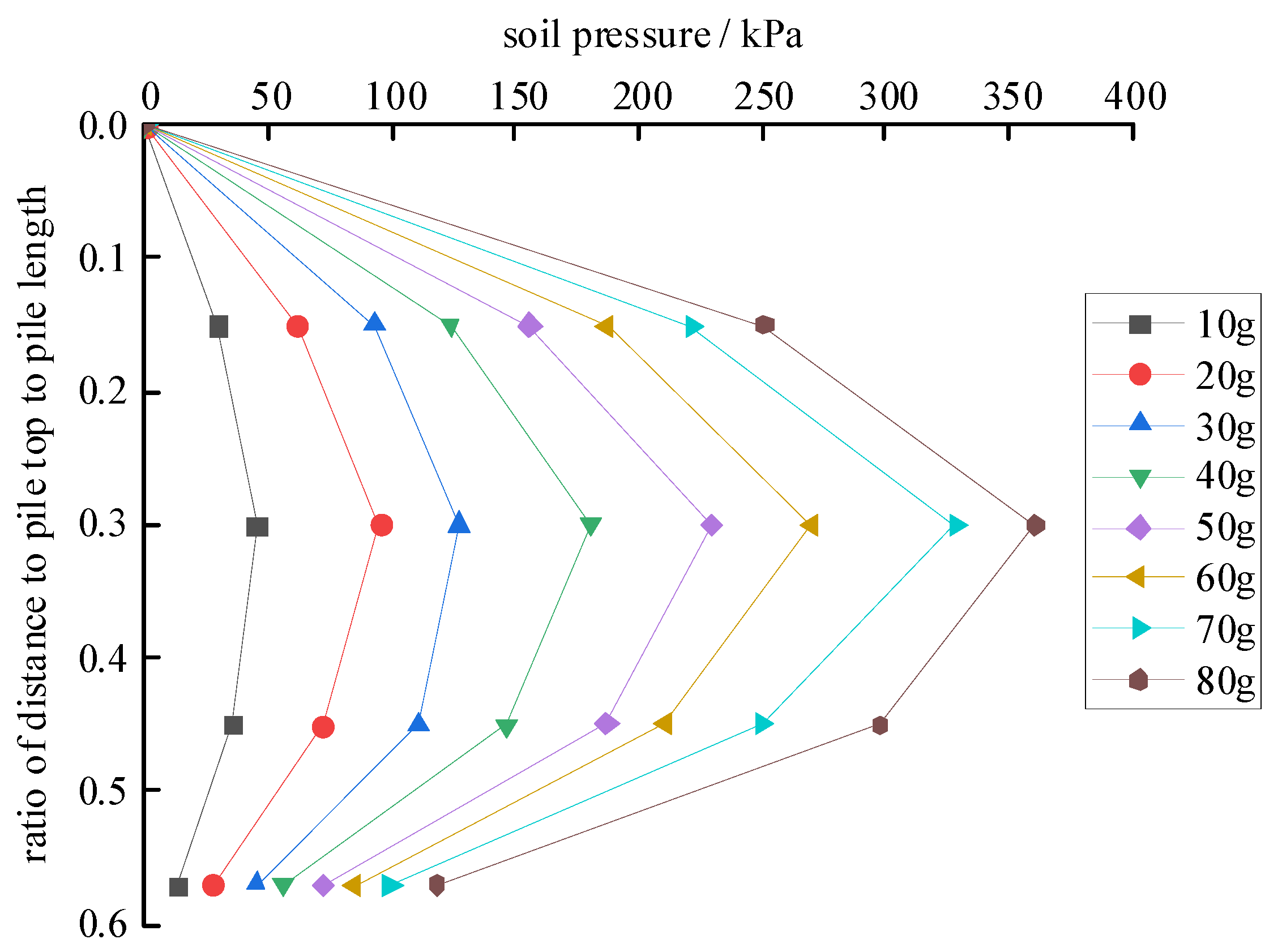
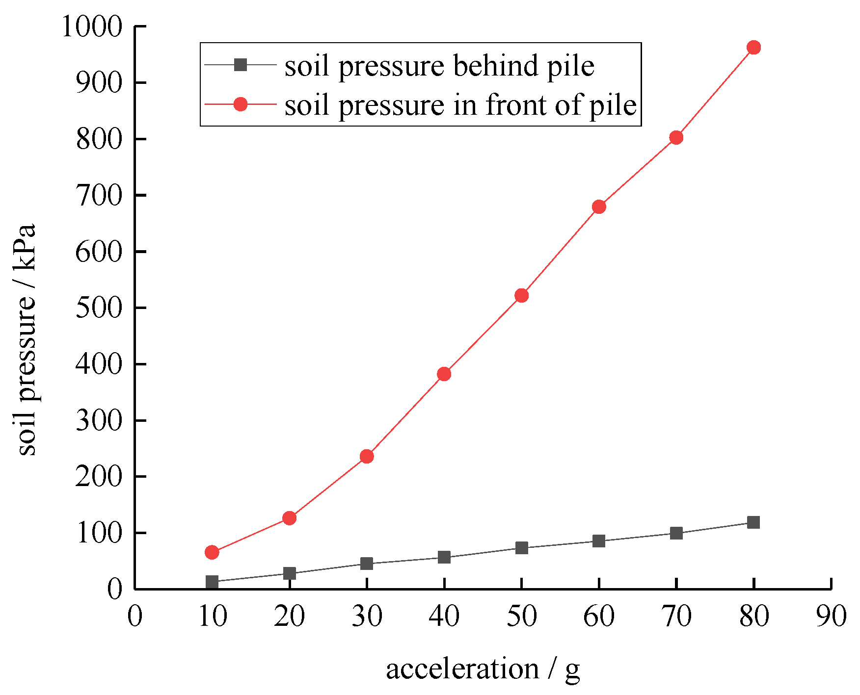
- Distribution of soil pressure behind piles
- (3)
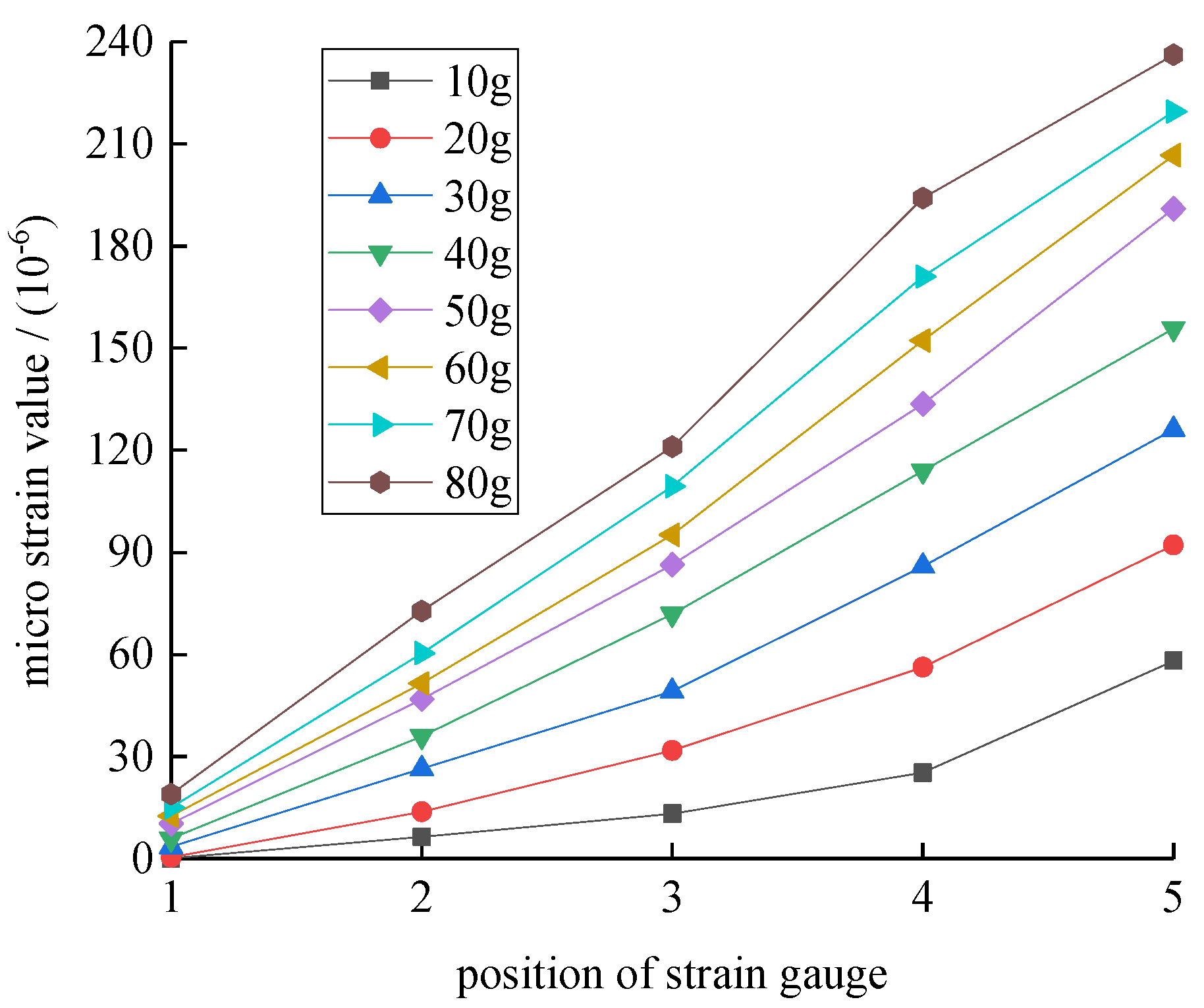
- The strain value on the tested anchor rods
3.2. Structural Force Analysis of the Frame-Anchor Support Section
- (1)
- Distribution of soil pressure on the frames
- (2)
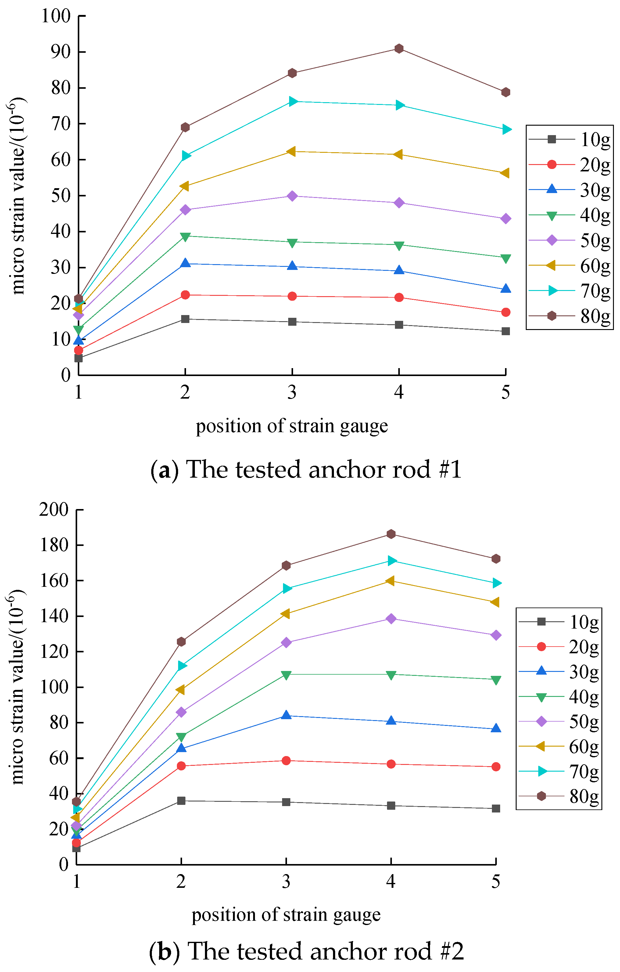
- The strain value on the tested anchor rods
3.3. Slope Deformation Characteristics
4. Suggestions for the Design of Combined Support of a Pile-Anchor and Frame-Anchor for Multi-Level Soil Slopes
- (1)
- The potential deformation range of the frame-anchor support section is greatly influenced by the anchoring depth of the anchor rods. The design should strictly control the anchoring depth of the anchor rods, so that the potential sliding surface can move backwards, thereby increasing the sliding path;
- (2)
- In the pile-anchor support section, the improvement effect of anchor rods on the pile bending moment depends on whether the anchoring force can be effectively exerted. The support design should ensure that the anchor rods have sufficient length to anchor with deep soil, providing greater anchoring force and effectively improving the bearing capacity of the pile.
5. Conclusions
- (1)
- The combined support structure of pile-anchors and frame-anchors had a good reinforcing effect on the multi-layer soil slope, but the deformation range of the slope was greatly influenced by the support structure, and the anchor rods were not in the absolutely stable soil layer.
- (2)
- In the pile-anchor support section, the anchoring force of the anchor rods was the highest, and the anchoring force effectively improved the bearing capacity of the pile. The bending moment followed an S-shaped distribution from top to bottom, with the maximum bending moment located at the foot of the slope. The soil pressure behind the pile was parabolic in distribution from top to bottom, and the resultant force point was between 1/3~1/2 of the height of the pile support section.
- (3)
- In the frame-anchor support section, the anchoring structure had a significant impact on the deformation range of the slope, and the anchor rods were not anchored in a stable soil layer. The strain values were distributed in an upward convex shape along the axial direction of the anchor rods. At different loading stages, the maximum axial strain was located at different monitoring points. The lateral frictional resistance at the end of the anchor rods occurred first and then gradually extended outward. The soil pressure on the frame gradually increased from top to bottom. The displacement trend of the slope was more obvious at the position where the soil pressure was higher, and the corresponding anchoring force of the anchor rods was also greater.
- (4)
- The deformation range of multi-level soil slopes was greatly influenced by the support structure. The design of the frame-anchor support section should strictly control the anchoring depth of the anchor rods, so as to make the potential sliding face move backward and increase the difficulty of sliding. The design of the pile-anchor support section should ensure that the anchor rods have sufficient length to provide greater anchoring force, thereby improving the bearing capacity of the pile.
Author Contributions
Funding
Data Availability Statement
Conflicts of Interest
References
- Qiu, H.J.; Regmi, A.D.; Cui, P.; Cao, M.M.; Lee, J.Z.; Zhu, X.H. Size distribution of loess slides in relation to local slope height within different slope morphologies. Catena 2016, 145, 155–163. [Google Scholar] [CrossRef]
- Zhao, X.Y.; Huang, J.H.; Zhou, Y.W.; Li, Y.L.; Jiang, C.S.; Yue, Z.Y. Joint reinforcement design method of tieback anchors on slope surface and anti-slide piles at slope toe. J. Southwest Jiaotong Univ. 2017, 52, 489–495. [Google Scholar] [CrossRef]
- Zhu, Y.P.; Cheng, D.; Yang, K.B.; Liu, D.R. Study on calculation model of anchor cable micro pile group considering elastoplastic deformation of soil in front of embedded pile. Adv. Eng. Sci. 2023. [Google Scholar] [CrossRef]
- Ye, W.N.; Zhou, Y.; Ye, S.H. Analysis of deformation and stress characteristics of anchored-frame structures for slope stabilization. Adv. Civ. Eng. 2020, 2020, 8870802. [Google Scholar] [CrossRef]
- Chen, J.F.; Chen, S.X.; Du, C.C.; Shi, Z.M.; Peng, M. Research on the mechanical mechanism of composite structure of anti-slide pile and anchor cable frame beam. J. Railw. Eng. Soc. 2021, 38, 7–12. [Google Scholar] [CrossRef]
- Han, A.M.; Li, J.G.; Xiao, J.H.; Xu, H.Z. Mechanical behaviors of frame beam supporting structure with prestressed anchors. Rock Soil Mech. 2010, 31, 2894–2900. [Google Scholar] [CrossRef]
- Lin, Y.L.; Li, Y.X.; Zhao, L.H.; Yang, T.Y. Investigation on seismic response of a three-stage soil slope supported by anchor frame structure. J. Cent. South Univ. 2020, 27, 1290–1305. [Google Scholar] [CrossRef]
- Yang, G.L.; Li, Q.H.; Duan, J.Y.; Luo, G.J.; Xiao, H.B.; Yang, T.Y. Field investigation on mechanical properties of multi-stage combined supporting structure for expansive soil high slopes. J. Cent. South Univ. (Sci. Technol.) 2022, 53, 171–180. [Google Scholar] [CrossRef]
- Hao, J.B.; Li, J.H.; Cheng, T.; Men, Y.M.; Wang, B.Q. Experimental study of slopes supported with framed anchors on shaking table. Chin. J. Rock Mech. Eng. 2015, 34, 293–304. [Google Scholar] [CrossRef]
- Hao, J.B.; Wang, B.Q.; Li, N. Test on failure characteristics of pressure-type anchor with lattice beam under earthquake. China J. Highw. Transp. 2017, 30, 20–27+37. [Google Scholar] [CrossRef]
- Han, D.D.; Men, Y.M.; Hu, Z.J. Experimental study of anti-sliding mechanism and force of lattice anchor in soil landslide. Rock Soil Mech. 2020, 41, 1189–1194+1202. [Google Scholar] [CrossRef]
- Zhang, J.J.; Niu, J.Y.; Fu, X.; Cao, L.C.; Yan, S.J. Failure modes of slope stabilized by frame beam with prestressed anchors. Eur. J. Environ. Civ. Eng. 2022, 26, 2120–2142. [Google Scholar] [CrossRef]
- Wang, C.T.; Wang, H.; Zhang, Y.F.; Qin, W.M.; Min, H. Model test and numerical simulation study on the mechanical characteristics of the anchored slide-resistant pile for stabilizing the colluvial landslide. Rock Soil Mech. 2020, 41, 3343–3354. [Google Scholar] [CrossRef]
- Chen, J.F.; Du, C.C.; Qi, H.; Peng, M.; Shi, Z.M. Visual modeling experiment of soil slopes stabilized with anchored piles and anchor cable frame beams. J. Tongji Univ. (Nat. Sci.) 2023, 51, 206–212. [Google Scholar] [CrossRef]
- Yang, K.B.; Zhu, Y.P.; Wu, L.P.; Duan, X.G.; Shi, D.B.; Du, X.T. Analysis on deformation failure and structural mechanical characteristics of multi-stage loess slope supported by frame structure with anchors. Adv. Civ. Eng. 2022. [Google Scholar] [CrossRef]
- Li, T.B.; Tian, X.L.; Han, W.X.; Ren, Y.; He, Y.; Wei, Y.X. Centrifugal model tests on sliding failure of a pile-stabilized high fill slope. Rock Soil Mech. 2013, 34, 3061–3070. [Google Scholar] [CrossRef]
- Zhang, G.; Cao, J.; Wang, L.P. Centrifuge model tests of deformation and failure of nailing-reinforced slope under vertical surface loading conditions. Soils Found. 2013, 53, 117–129. [Google Scholar] [CrossRef]
- Wang, Y.F.; Cheng, Q.G.; Huang, Y.R. Centrifuge tests on excavation of high loess slope with different reinforcement modes. Chin. J. Rock Mech. Eng. 2014, 33, 1032–1046. [Google Scholar] [CrossRef]
- Nakamoto, S.; Iwasa, N.; Takemura, J. Centrifuge modelling of rock bolts with facing plates. Int. J. Phys. Model. Geotech. 2018, 18, 21–32. [Google Scholar] [CrossRef]
- Luo, F.Y.; Zhang, G.; Liu, Y.; Ma, C.H. Centrifuge modeling of the geotextile reinforced slope subject to drawdown. Geotext. Geomembr. 2018, 46, 11–21. [Google Scholar] [CrossRef]
- Liu, S.J.; Luo, F.Y.; Zhang, G. Pile reinforcement behavior and mechanism in a soil slope under drawdown conditions. Bull. Eng. Geol. Environ. 2021, 80, 4097–4109. [Google Scholar] [CrossRef]
- Yuan, B.X.; Liang, J.K.; Zhang, B.F.; Chen, W.J.; Huang, X.L.; Huang, Q.Y.; Li, Y.; Yuan, P. Optimized reinforcement of granite residual soil via a cement and alkaline solution: A coupling effect. J. Rock Mech. Geotech. Eng. 2024. [Google Scholar] [CrossRef]
- Yuan, B.X.; Chen, W.J.; Li, Z.H.; Zhao, J.; Luo, Q.Z.; Chen, W.W.; Chen, T.Y. Sustainability of the polymer SH reinforced recycled Granite Residual Soil: Properties, physicochemical mechanism and applications. J. Soils Sediments 2023, 23, 246–262. [Google Scholar] [CrossRef]
- Liu, J.; Cui, P. Influence of water-soil chemical interaction on cohesive force: A case study of montmorillonite-quartz remolded soil. Rock Soil Mech. 2017, 38, 419–427+434. [Google Scholar] [CrossRef]
- Zhang, T.; Men, Y.M.; Shi, S.W.; Li, X.C. Comparative model test of anti-slide anchor pile and common anti-slide pile to reinforce loess landslide. J. Yangtze River Sci. Res. Inst. 2017, 34, 70–76. [Google Scholar] [CrossRef]


| Stratum | Density (kg/m3) | Cohesion (kPa) | Internal Friction Angle (°) |
|---|---|---|---|
| Loess | 1650 | 15 | 25 |
| Sandstone | 2200 | 150 | 35 |
| Physical Quantity | Prototype | Model | Physical Quantity | Prototype | Model |
|---|---|---|---|---|---|
| acceleration | 1 | angle | 1 | 1 | |
| length | 1 | density | 1 | 1 | |
| area | 1 | moisture content | 1 | 1 | |
| volume | 1 | cohesion | 1 | 1 | |
| displacement | 1 | internal friction angle | 1 | 1 | |
| stress | 1 | 1 | particle size | 1 | 1 |
| bending moment | 1 | inertia time | 1 |
| Stratum | Density (kg/m3) | Cohesion (kPa) | Internal Friction Angle (°) |
|---|---|---|---|
| Loess | 1750 | 15.5 | 24.6 |
| Sandstone | 1835 | 161 | 35.2 |
Disclaimer/Publisher’s Note: The statements, opinions and data contained in all publications are solely those of the individual author(s) and contributor(s) and not of MDPI and/or the editor(s). MDPI and/or the editor(s) disclaim responsibility for any injury to people or property resulting from any ideas, methods, instructions or products referred to in the content. |
© 2024 by the authors. Licensee MDPI, Basel, Switzerland. This article is an open access article distributed under the terms and conditions of the Creative Commons Attribution (CC BY) license (https://creativecommons.org/licenses/by/4.0/).
Share and Cite
Yang, K.; Zhu, Y.; Guo, H.; Xie, Y.; Wang, Z. Centrifugal Model Test of Multi-Level Slope under Combined Support of Pile-Anchor and Frame-Anchor. Buildings 2024, 14, 2680. https://doi.org/10.3390/buildings14092680
Yang K, Zhu Y, Guo H, Xie Y, Wang Z. Centrifugal Model Test of Multi-Level Slope under Combined Support of Pile-Anchor and Frame-Anchor. Buildings. 2024; 14(9):2680. https://doi.org/10.3390/buildings14092680
Chicago/Turabian StyleYang, Kuibin, Yanpeng Zhu, Hong Guo, Yongbin Xie, and Zhiqiang Wang. 2024. "Centrifugal Model Test of Multi-Level Slope under Combined Support of Pile-Anchor and Frame-Anchor" Buildings 14, no. 9: 2680. https://doi.org/10.3390/buildings14092680