
Strength Model for Prestressed Concrete Beams Subjected to Pure Torsion


Abstract
:1. Introduction
2. Torsional Strength Model for Prestressed Concrete Beams
2.1. Assumptions and Shear Element
2.2. Effect of Prestress
2.3. Multipotential Capacity
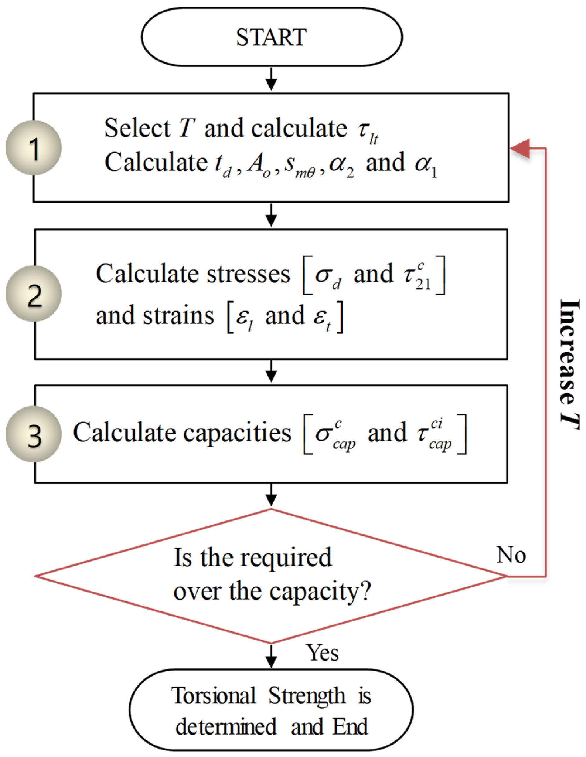
2.4. Calculation Procedure for Torsional Strength
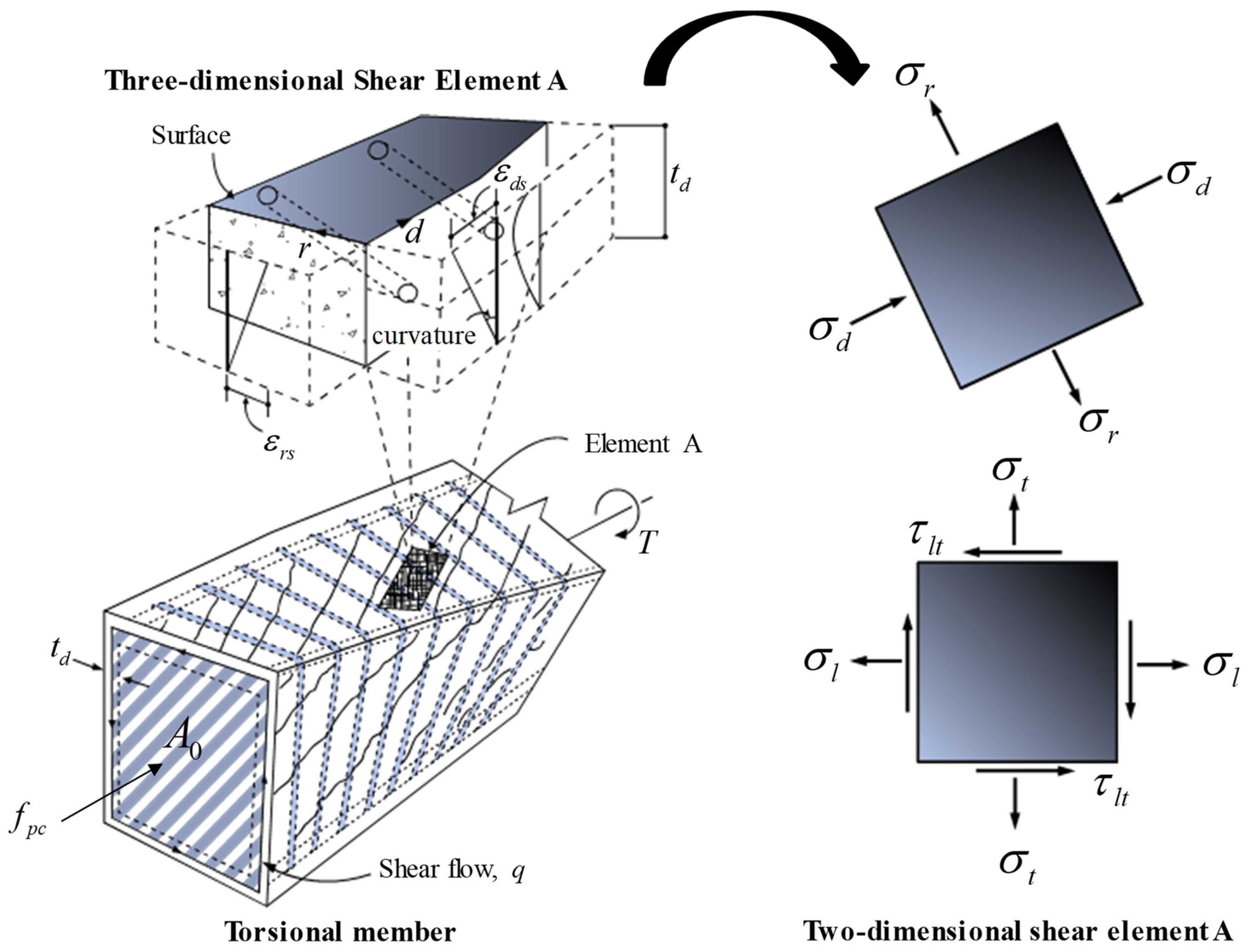
- Considering the assumed torsional moment acting on a given section with material properties, the shear stress () due to torsion () is calculated using Equation (1). The torsional effective thickness () is calculated using Equation (22) to determine the (). The average shear crack spacing (), initial crack angle (), and principal stress angle () are calculated using Equations (27), (16), and (18).
- Estimation of stresses and strains in the shear element. The principal compressive stress () and shear stress () at the crack surface are calculated using Equations (11) and (13), respectively, and the longitudinal strain () and transverse strain () are calculated using Equations (19) and (20), respectively.
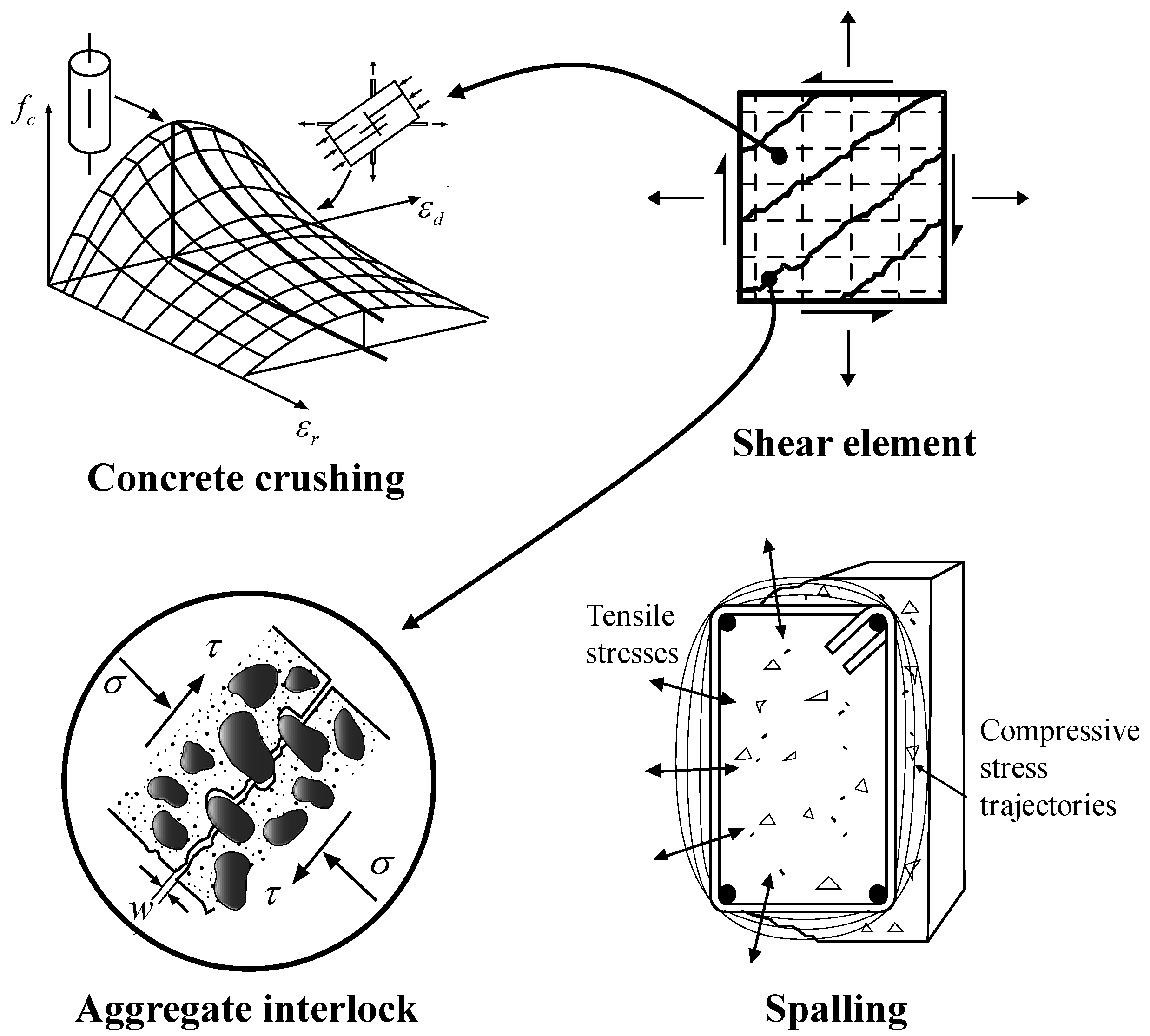
- The torsional strength of the member is then determined by checking whether the previously calculated principal compressive stress () and shear stress at the crack surface () reached the compressive failure () and aggregate engagement failure criteria () in Equations (23) and (24), respectively.
3. Verification of the Proposed Model
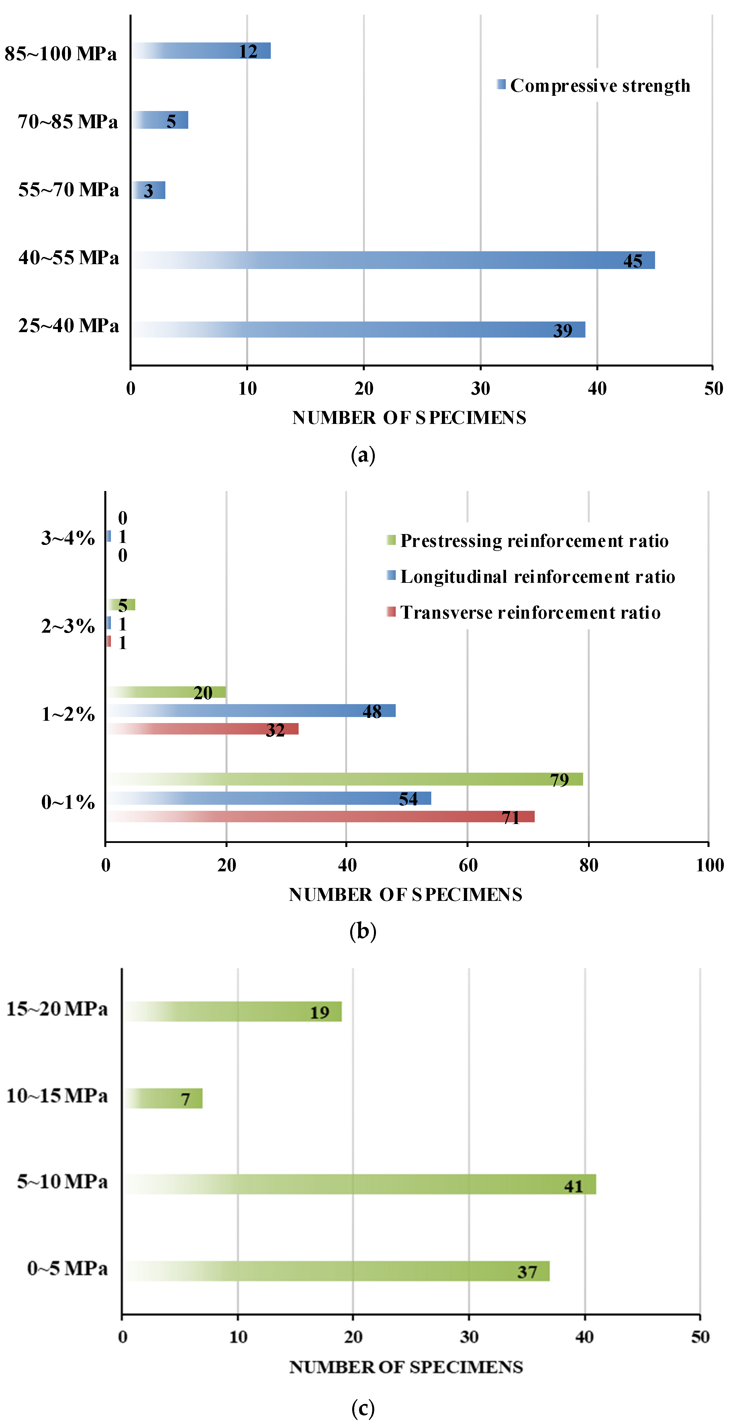
3.1. Experimental Data of Prestressed Concrete Beams Subjected to Pure Torsion
3.2. Torsional Strength Model Specified in ACI 318-19
3.3. Contributions of Tube End Reinforcements
4. Conclusions
- (1)
- Assuming the principal tensile stress and principal compressive strain to be zero in the shear element of a reinforced concrete member subjected to torsion in the ultimate state, and a torsional strength model was derived by simplifying the force equilibrium and strain compatibility conditions.
- (2)
- In the derivation of the torsional strength model, the effects of the initial crack angle, principal stress angle, longitudinal strain, and torsional effective thickness in the shear element were considered, considering the effective prestress acting on the prestressed concrete member.
- (3)
- Based on the multipotential capacity criteria, the failure mode was categorized into a compressive failure of concrete and aggregate interlocking failure at the crack surface, and the effect of prestress was reflected in the crack width calculation formula to determine the aggregate interlocking in a rational manner.
- (4)
- The results of the torsional strength evaluation that included the effect of prestress show a mean value of 1.123 for the experimental-to-calculated ratio and a COV of 17.7% for the 104 specimens collected from the literature, showing better accuracy than the estimation results without considering prestress, which had a mean of 1.691 and a COV of 30.5%.
- (5)
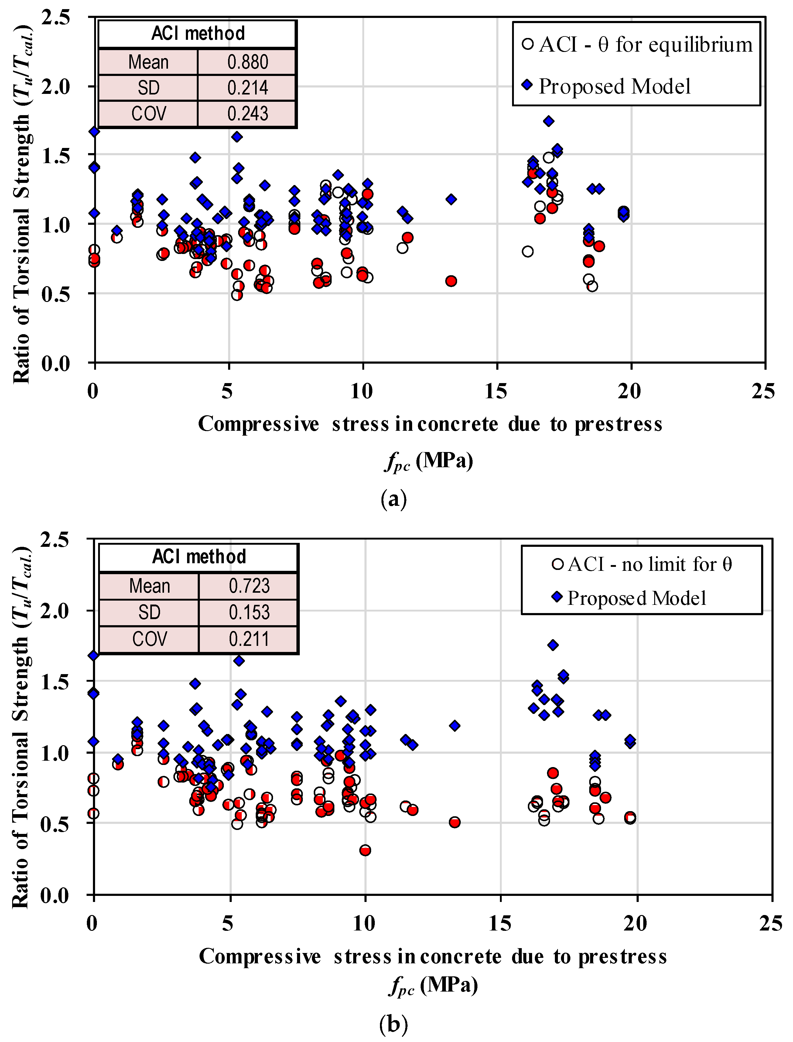
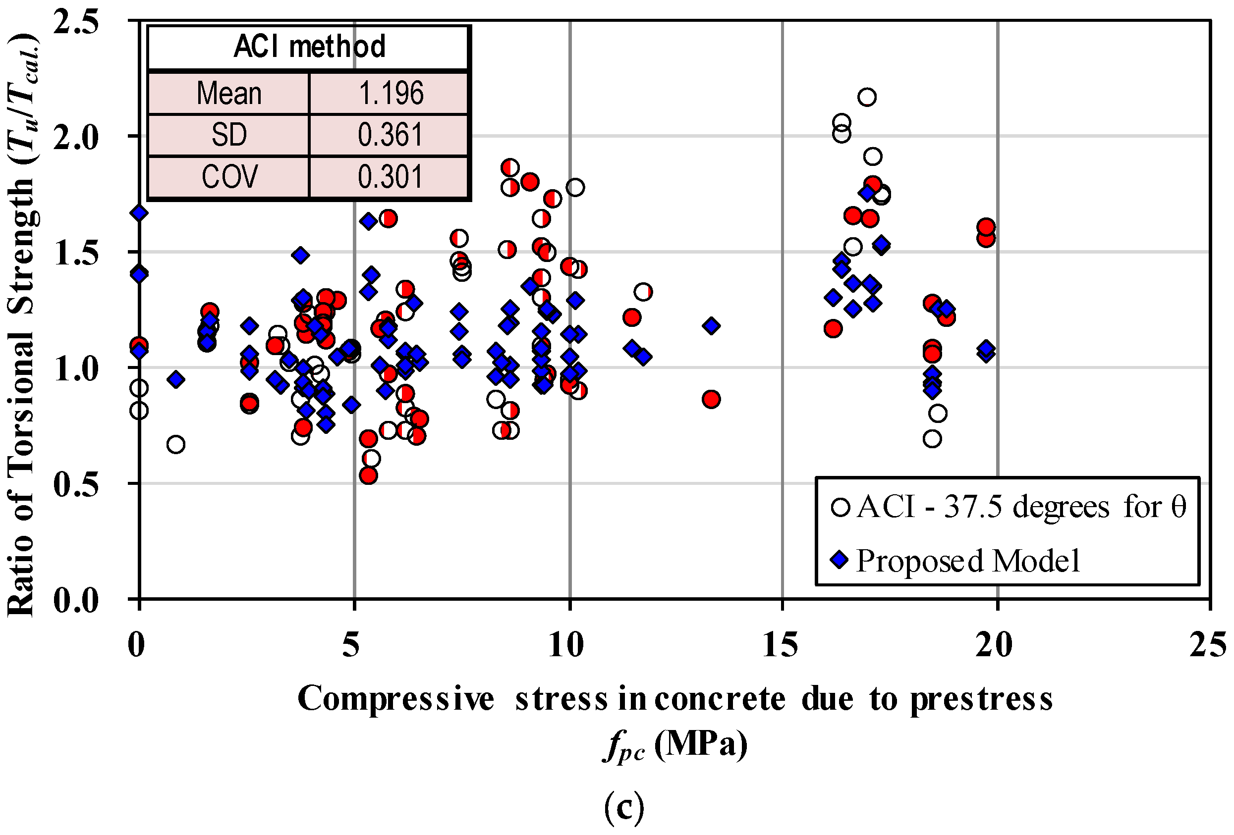
- The torsional strength of the experimental specimens was evaluated according to the ACI 318-19 with a mean of 0.880 and COV of 24.3%, which is less accurate than the proposed model and significantly unsafe. When the compressive diagonal angle of prestressed concrete beams was set to according to ACI 318, the torsional strength of the specimens was evaluated with improved accuracy, with a mean of 1.196 and COV of 30.1%.
- (6)
- The proposed model reasonably reflects the influence of prestress and evaluates the strength of prestressed concrete beams subjected to a pure torsional moment with good accuracy. However, this study intended to provide some insight into the torsional behavior of prestressed concrete beams, and there is seldom pure torsion for box girders in real practice. Thus, this model is expected to be extended to the strength evaluation model of prestressed concrete beams resisting torsional moment in combination with bending moment, shear force, and axial force in the future.
Author Contributions
Funding
Data Availability Statement
Conflicts of Interest
References
- Ju, H.; Lee, D.H.; Hwang, J.H.; Kang, J.W.; Kim, J.S.; Oh, Y.H. Torsional Behavior Model of Steel Fiber-Reinforced Concrete Members Modifying Fixed-Angle Softened-Truss Model. Compos. Part B Eng. 2013, 45, 215–231. [Google Scholar] [CrossRef]
- Ju, H.; Lee, D.H.; Hwang, J.H.; Kim, K.S.; Oh, Y.H. Fixed-Angle Smeared-Truss Approach with Direct Tension Force Transfer Model for Torsional Behavior of Steel Fiber-Reinforced Concrete Members. J. Adv. Concr. Technol. 2013, 11, 215–229. [Google Scholar] [CrossRef]
- Ju, H.; Lee, D.; Zhang, W.; Wang, L. Torsional Strength Model of Reinforced Concrete Members Subjected to Combined Loads. Comput. Concr. 2022, 29, 285–301. [Google Scholar]
- Han, S.J.; Ju, H.; Joo, H.E.; Kim, K.S. Shear resistance mechanism of prefabricated large-scale gerber girder. J. Build. Eng. 2024, 83, 108424. [Google Scholar] [CrossRef]
- Meiramov, D.; Seo, Y.; Ju, H.; Cho, H.C. Direct Tensile Capacity of Steel Tube Connections in Precast Concrete Double-Wall System. Building 2023, 13, 2872. [Google Scholar] [CrossRef]
- Ju, H.; Han, S.J.; Choi, I.S.; Choi, S.; Park, M.K.; Kim, K.S. Experimental Study on Optimized-Section Precast Slab with Structural Aesthetics. Appl. Sci. 2018, 8, 123. [Google Scholar] [CrossRef]
- Ju, H.; Kim, K.S.; Lee, D.H.; Hwang, J.H.; Choi, S.H.; Oh, Y.H. Torsional Responses of Steel Fiber-Reinforced Concrete Members. Compos. Struct. 2015, 129, 143–156. [Google Scholar] [CrossRef]
- Ju, H.; Han, S.J.; Kim, K.S. Analytical Model for Torsional Behavior of RC Members Combined with Bending, Shear, and Axial Loads. J. Build. Eng. 2020, 32, 101730. [Google Scholar] [CrossRef]
- Ju, H.; Lee, D. Nonlinear Analysis of RC Members Subjected to Combined Torsion and Bending Moment. ACI Struct. J. 2021, 118, 55–70. [Google Scholar]
- Kryzhanovskiy, K.; Zhang, D.; Ju, H.; Kim, J. Development of Torsional Strength Model for Steel Fiber Reinforced Concrete Beams with Transverse Reinforcement. Int. J. Civ. Eng. 2023, 21, 1123–1139. [Google Scholar] [CrossRef]
- Bredt, R. Kritische Bemerkungen zur Drehungselastizitat. Z Vereines Deutscher Ingenieure. Band 1896, 40, 785–790. [Google Scholar]
- Hsu, T.T.C.; Zhang, L.X. Nonlinear analysis of membrane elements by fixed-angle softened-truss model. ACI Struct. J. 1997, 94, 483–492. [Google Scholar]
- Hsu, T.T.C.; Mo, Y.L. Unified Theory of Concrete Structures; Wiley and Sons: Hoboken, NJ, USA, 2010. [Google Scholar]
- Rahal, K.N.; Collins, M.P. Effect of Thickness of Concrete Cover on Shear-Torsion Interaction—An Experimental Investigation. ACI Struct. J. 1995, 92, 334–342. [Google Scholar]
- Greene, G.G.; Belarbi, A. Model for Reinforced Concrete Members under Torsion, Bending, and Shear. I: Theory. J. Eng. Mech. 2009, 135, 961–969. [Google Scholar] [CrossRef]
- Mitchell, D.; Collins, M.P. Diagonal compression field theory—A rational model for structural concrete in pure torsion. ACI J. 1974, 71, 396–408. [Google Scholar]
- Bentz, E.C.; Collins, M.P. Development of the 2004 Canadian Standards Association (CSA) A23.3 Shear Provisions for Reinforced Concrete. Can. J. Civ. Eng. 2006, 33, 521–534. [Google Scholar] [CrossRef]
- Vecchio, F.J.; Collins, M.P. Modified Compression Field Theory for Concrete Elements Subjected to Shear. ACI J. 1986, 83, 219–231. [Google Scholar]
- Haddadin, M.J.; Hong, S.T.; Mattock, A.H. Stirrup Effectiveness in Reinforced Concrete Beams with Axial Force. Proc. Am. Soc. Civ. Eng. 1971, 97, 2277–2297. [Google Scholar] [CrossRef]
- Park, R.; Paulay, T. Reinforced Concrete Structures; Wiley: New York, NY, USA, 1975. [Google Scholar]
- Ju, H.; Han, S.J.; Kim, K.S.; Strauss, A.; Wu, W. Multi-Potential Capacity for Reinforced Concrete Members under Pure torsion. Struct. Eng. Mech. 2020, 75, 401–414. [Google Scholar]
- Hsu, T.T.C. Torsion of Reinforced Concrete; Van Nostrand Reinhold, Inc.: New York, NY, USA, 1984. [Google Scholar]
- Hsu, T.T.C.; Mo, Y.L. Softening of concrete in torsional members—Theory and Tests. ACI J. 1985, 82, 290–303. [Google Scholar]
- Hsu, T.T.C.; Mo, Y.L. Softening of concrete in torsional members—Prestressed Concrete. ACI J. 1985, 82, 603–615. [Google Scholar]
- Lee, J.Y.; Kim, K.H.; Kim, S.W. Non-linear shear analysis of reinforced concrete columns by fixed-angle theory. Proc. Inst. Civil Eng. Struc. Build. 2013, 166, 165–181. [Google Scholar] [CrossRef]
- Voo, J.Y.L.; Foster, S.J. Variable Engagement Model for Fiber Reinforced Concrete in Tension; UNICIV Report No. R-420; University of New South Wales: Sydney, Australia, 2003. [Google Scholar]
- Lee, J.Y.; Kim, S.W. Torsional strength of RC beams considering tension stiffening effect. J. Struct. Eng. 2010, 136, 1367–1378. [Google Scholar] [CrossRef]
- Jeng, C.H.; Hsu, T.T.C. A Softened Membrane Model for Torsion in Reinforced Concrete Members. Eng. Struct. 2009, 32, 1944–1954. [Google Scholar] [CrossRef]
- ACI 318-19; ACI Committee 318, Building Code Requirements for Structural Concrete (ACI 318-19). American Concrete Institute: Farmington Hills, MI, USA, 2019.
- McMullen, A.E.; EI-Degwy, W.M. Prestressed Concrete Tests Compared with Torsion Theories. PCI J. 1985, 30, 96–127. [Google Scholar] [CrossRef]
- Rahal, K.N. Evaluation of AASHTO-LRFD General Procedure for Torsion and Combined Loading. ACI Struct. J. 2006, 103, 683–692. [Google Scholar]
- Allos, A.E.; Rashid, A.H. Prestressed Concrete Rectangular Beams Subjected to Sustained Torque. ACI Struct. J. 1989, 86, 469–472. [Google Scholar]
- Ashour, S.A.; Shihata, S.A.; Akhtaruzaman, A.A.; Wafa, F.F. Prestressed high-strength concrete beams under torsion and bending. Can. J. Civ. Eng. 1999, 26, 197–207. [Google Scholar] [CrossRef]
- Chander, H. Behavior of Prestressed Concrete Rectangular Members Subjected to Pure Torsion. Doctoral Dissertation, West Virginia University, Morgantown, WV, USA, 1970. [Google Scholar]
- Wafa, F.F.; Shihata, S.A.; Ashour, S.A.; Akhtaruzzaman, A.A. Prestressed high-strength concrete beams under torsion. J. Struct. Eng. 1995, 121, 1280–1286. [Google Scholar] [CrossRef]
- Jeng, C.H.; Chao, M. Torsion Experiment and Cracking-Torque Formulas of Prestressed Concrete Beams. ACI Struct. J. 2018, 115, 1267–1278. [Google Scholar] [CrossRef]
- Mitchell, D.; Collins, M.P. The Behaviour of Structural Concrete Beams in Pure Torsion; Publication No. 74-06. Ph.D. Thesis, Department of Civil Engineering, University of Toronto, Toronto, ON, USA, 1974. [Google Scholar]
- Mukherjee, P.R. Ultimate Torsional Strength Of Plain, Prestressed And Reinforced Concrete members Of Rectangular Cross-Section. Ph.D. Thesis, West Virginia University, Morgantown, WV, USA, 1967. [Google Scholar]
- Ju, H.; Han, S.J.; Zhang, D.; Kim, J.; Wu, W.; Kim, K.S. Estimation on Minimum Torsional Reinforcement of Reinforced Concrete and Steel Fiber Reinforced Concrete Members. Adv. Mater. Sci. Eng. 2019, 2019, 4595363. [Google Scholar] [CrossRef]
- Joint ACI-ASCE Committee 445. 445.1R-12 Report on Torsion in Structural Concrete; American Concrete Institute: Farmington Hills, MI, USA, 2013. [Google Scholar]
- Ju, H.; Lee, D.; Kim, K.H.; Yerzhanov, M.; Zhang, D.; Kim, J.R. Torsional Design Method Used in Eurasia Region: A Comparative Study. Struct. Concr. 2021, 22, 3798–3834. [Google Scholar] [CrossRef]


| Author | Beam Name | fck | fly | Esl | fpy | Eps | fty | Est | B | H | Al | Aps | fpe | At | x0 | y0 | s | Tcr | Tu |
|---|---|---|---|---|---|---|---|---|---|---|---|---|---|---|---|---|---|---|---|
| (MPa) | (MPa) | (MPa, ×105) | (MPa) | (MPa, ×105) | (MPa) | (MPa, ×105) | (mm) | (mm) | (mm2) | (mm2) | (Mpa) | (mm2) | (mm) | (mm) | (mm) | (kNm) | (kNm) | ||
| Mitchell et al. (1974) [16] | PT4 * | 28.61 | 424.03 | 2.00 | 0 | 0.00 | 328 | 2.00 | 381.0 | 381 | 1600.00 | 0.00 | 0.00 | 71.00 | 346.2 | 346.2 | 101.6 | - | 65.42 |
| PT5 * | 33.78 | 424.03 | 2.00 | 0 | 0.00 | 328 | 2.00 | 355.6 | 355.6 | 1600.00 | 0.00 | 0.00 | 71.00 | 342.9 | 342.9 | 101.6 | - | 57.62 | |
| PT6 * | 32.54 | 424.03 | 2.00 | 0 | 0.00 | 328 | 2.00 | 431.8 | 431.8 | 1600.00 | 0.00 | 0.00 | 71.00 | 342.9 | 342.9 | 101.6 | - | 64.40 | |
| P1 | 32.27 | 327.50 | 2.00 | 1475 | 1.97 | 328 | 2.00 | 355.6 | 431.8 | 570.40 | 462.96 | 1144.25 | 71.00 | 320.8 | 397.0 | 96.5 | - | 81.91 | |
| P2 * | 32.89 | 327.50 | 2.00 | 1475 | 1.97 | 328 | 2.00 | 355.6 | 431.8 | 570.40 | 462.96 | 1162.89 | 71.00 | 320.8 | 397.0 | 96.5 | - | 86.21 | |
| P3 | 33.99 | 327.50 | 2.00 | 1475 | 1.97 | 328 | 2.00 | 355.6 | 431.8 | 427.80 | 115.74 | 1140.93 | 71.00 | 320.8 | 397.0 | 96.5 | - | 53.10 | |
| P4 * | 31.72 | 327.50 | 2.00 | 1475 | 1.97 | 328 | 2.00 | 355.6 | 431.8 | 570.40 | 462.96 | 1143.70 | 71.00 | 320.8 | 397.0 | 96.5 | - | 85.42 | |
| P5 | 38.89 | 0.00 | 0.00 | 1475 | 1.97 | 328 | 2.00 | 355.6 | 431.8 | 0.00 | 1543.20 | 1143.25 | 71.00 | 320.8 | 397.0 | 96.5 | - | 97.73 | |
| P6 | 38.89 | 379.21 | 1.97 | 0 | 0.00 | 328 | 2.00 | 355.6 | 431.8 | 6000.00 | 0.00 | 0.00 | 71.00 | 320.8 | 397.0 | 96.5 | - | 88.13 | |
| Chander et. al. (1970) [34] | C/1 | 38.36 | 335.77 | 2.00 | 1855 | 1.94 | 335 | 2.00 | 101.6 | 304.8 | 285.20 | 198.06 | 594.25 | 31.67 | 69.9 | 273.1 | 101.6 | 5.87 | 6.70 |
| E/2 ** | 38.36 | 335.77 | 2.00 | 1855 | 1.94 | 335 | 2.00 | 101.6 | 304.8 | 285.20 | 198.06 | 608.04 | 31.67 | 69.9 | 273.1 | 101.6 | 5.36 | 5.97 | |
| C/3 | 36.17 | 335.77 | 2.00 | 1855 | 1.94 | 335 | 2.00 | 101.6 | 304.8 | 285.20 | 198.06 | 719.66 | 31.67 | 69.9 | 273.1 | 76.2 | 7.85 | 8.93 | |
| E/4 ** | 36.17 | 335.77 | 2.00 | 1855 | 1.94 | 335 | 2.00 | 101.6 | 304.8 | 285.20 | 198.06 | 775.65 | 31.67 | 69.9 | 273.1 | 76.2 | 6.15 | 7.31 | |
| C/5 | 40.40 | 335.77 | 2.00 | 1855 | 1.94 | 335 | 2.00 | 101.6 | 304.8 | 285.20 | 297.10 | 974.52 | 31.67 | 69.9 | 273.1 | 101.6 | 8.52 | 8.54 | |
| E/6 ** | 40.40 | 335.77 | 2.00 | 1855 | 1.94 | 335 | 2.00 | 101.6 | 304.8 | 285.20 | 297.10 | 974.52 | 31.67 | 69.9 | 273.1 | 101.6 | 7.43 | 7.93 | |
| C/9 | 38.53 | 335.77 | 2.00 | 1855 | 1.94 | 335 | 2.00 | 101.6 | 304.8 | 285.20 | 297.10 | 977.38 | 31.67 | 69.9 | 273.1 | 76.2 | 8.54 | 9.62 | |
| E/10 ** | 38.53 | 335.77 | 2.00 | 1855 | 1.94 | 335 | 2.00 | 101.6 | 304.8 | 285.20 | 297.10 | 977.38 | 31.67 | 69.9 | 273.1 | 76.2 | 8.51 | 9.00 | |
| C/11 | 45.84 | 335.77 | 2.00 | 1855 | 1.94 | 335 | 2.00 | 101.6 | 304.8 | 285.20 | 594.19 | 852.57 | 31.67 | 69.9 | 273.1 | 101.6 | 10.27 | 10.68 | |
| E/12 ** | 45.84 | 335.77 | 2.00 | 1855 | 1.94 | 335 | 2.00 | 101.6 | 304.8 | 285.20 | 594.19 | 852.57 | 31.67 | 69.9 | 273.1 | 101.6 | 10.33 | 10.42 | |
| C/15 | 48.00 | 335.77 | 2.00 | 1855 | 1.94 | 335 | 2.00 | 101.6 | 304.8 | 285.20 | 594.19 | 901.34 | 31.67 | 69.9 | 273.1 | 76.2 | 12.02 | 12.02 | |
| E/16 ** | 48.00 | 335.77 | 2.00 | 1855 | 1.94 | 335 | 2.00 | 101.6 | 304.8 | 285.20 | 594.19 | 901.34 | 31.67 | 69.9 | 273.1 | 76.2 | 12.02 | 12.18 | |
| C/7 | 37.67 | 335.77 | 2.00 | 1855 | 1.94 | 335 | 2.00 | 101.6 | 228.6 | 285.20 | 396.13 | 973.81 | 31.67 | 69.9 | 196.9 | 101.6 | 6.16 | 6.19 | |
| E/8 ** | 37.67 | 335.77 | 2.00 | 1855 | 1.94 | 335 | 2.00 | 101.6 | 228.6 | 285.20 | 396.13 | 973.81 | 31.67 | 69.9 | 196.9 | 101.6 | 5.11 | 5.70 | |
| C/13 | 43.53 | 335.77 | 2.00 | 1855 | 1.94 | 335 | 2.00 | 101.6 | 228.6 | 285.20 | 198.06 | 1016.43 | 31.67 | 69.9 | 196.9 | 101.6 | 6.17 | 6.68 | |
| E/14 ** | 43.53 | 335.77 | 2.00 | 1855 | 1.94 | 335 | 2.00 | 101.6 | 228.6 | 285.20 | 198.06 | 1016.43 | 31.67 | 69.9 | 196.9 | 101.6 | 6.46 | 6.99 | |
| C/17 | 34.38 | 335.77 | 2.00 | 1855 | 1.94 | 335 | 2.00 | 101.6 | 228.6 | 285.20 | 99.03 | 1023.75 | 31.67 | 69.9 | 196.9 | 101.6 | 3.93 | 4.64 | |
| E/18 ** | 34.38 | 347.50 | 2.00 | 1855 | 1.94 | 335 | 2.00 | 101.6 | 228.6 | 285.20 | 99.03 | 1023.75 | 31.67 | 69.9 | 196.9 | 101.6 | 4.06 | 4.67 | |
| C/19 | 35.45 | 347.50 | 2.00 | 1855 | 1.94 | 335 | 2.00 | 101.6 | 228.6 | 285.20 | 396.13 | 1158.18 | 31.67 | 69.9 | 196.9 | 101.6 | 5.34 | 5.83 | |
| E/20 ** | 35.45 | 393.00 | 2.00 | 1855 | 1.94 | 335 | 2.00 | 101.6 | 228.6 | 285.20 | 396.13 | 1158.18 | 31.67 | 69.9 | 196.9 | 101.6 | 5.77 | 6.00 | |
| SP1261 | 34.51 | 348.19 | 2.00 | 1855 | 1.94 | 359 | 2.00 | 152.4 | 304.8 | 506.80 | 396.13 | 1198.31 | 71.30 | 117.5 | 269.9 | 101.6 | 16.85 | 18.63 | |
| SP1262 | 34.51 | 393.00 | 2.00 | 1855 | 1.94 | 399 | 2.00 | 152.4 | 304.8 | 285.20 | 396.13 | 1198.31 | 31.67 | 120.7 | 273.1 | 101.6 | 11.74 | 15.21 | |
| SP1263 | 38.96 | 348.19 | 2.00 | 1855 | 1.94 | 359 | 2.00 | 152.4 | 304.8 | 506.80 | 396.13 | 1172.14 | 71.30 | 117.5 | 269.9 | 101.6 | 16.43 | 19.79 | |
| SP1264 | 38.96 | 393.00 | 2.00 | 1855 | 1.94 | 399 | 2.00 | 152.4 | 304.8 | 285.20 | 396.13 | 1172.14 | 31.67 | 120.7 | 273.1 | 101.6 | 13.58 | 15.38 | |
| SP1269 | 34.20 | 334.40 | 2.00 | 1855 | 1.94 | 356 | 2.00 | 152.4 | 304.8 | 506.80 | 396.13 | 724.71 | 71.30 | 117.5 | 269.9 | 101.6 | 15.95 | 17.08 | |
| SP1270 | 34.20 | 368.18 | 2.00 | 1855 | 1.94 | 411 | 2.00 | 152.4 | 304.8 | 285.20 | 396.13 | 724.71 | 31.67 | 120.7 | 273.1 | 101.6 | 14.68 | 14.68 | |
| SP1271 | 33.89 | 334.40 | 2.00 | 1855 | 1.94 | 356 | 2.00 | 152.4 | 304.8 | 506.80 | 396.13 | 728.46 | 71.30 | 117.5 | 269.9 | 101.6 | 16.43 | 18.35 | |
| SP1272 | 33.89 | 368.18 | 2.00 | 1855 | 1.94 | 411 | 2.00 | 152.4 | 304.8 | 285.20 | 396.13 | 728.46 | 31.67 | 120.7 | 273.1 | 101.6 | 12.64 | 13.68 | |
| SPEC I | 40.97 | 368.18 | 2.00 | 1855 | 1.94 | 411 | 2.00 | 152.4 | 304.8 | 285.02 | 396.13 | 874.32 | 31.67 | 120.7 | 273.1 | 101.6 | 17.19 | 17.19 | |
| SPEC II | 40.97 | 368.18 | 2.00 | 1855 | 1.94 | 411 | 2.00 | 152.4 | 304.8 | 285.02 | 396.13 | 874.32 | 31.67 | 120.7 | 273.1 | 101.6 | 14.52 | 16.12 | |
| SP1267 | 34.95 | 4334.40 | 2.00 | 1855 | 1.94 | 356 | 2.00 | 152.4 | 304.8 | 506.71 | 396.13 | 1174.14 | 71.26 | 117.5 | 269.9 | 101.6 | 18.16 | 19.12 | |
| SP1241 | 33.41 | 368.18 | 2.00 | 1855 | 1.94 | 419 | 2.00 | 101.6 | 304.8 | 285.02 | 198.06 | 1172.76 | 31.67 | 69.9 | 273.1 | 101.6 | 8.58 | 9.37 | |
| SP1242 | 33.41 | 368.18 | 2.00 | 1855 | 1.94 | 419 | 2.00 | 101.6 | 304.8 | 285.02 | 198.06 | 1172.76 | 31.67 | 69.9 | 273.1 | 101.6 | 8.43 | 9.20 | |
| SPC1243 | 36.54 | 368.18 | 2.00 | 1855 | 1.94 | 405 | 2.00 | 101.6 | 304.8 | 285.02 | 198.06 | 600.20 | 31.67 | 69.9 | 273.1 | 101.6 | 6.63 | 8.02 | |
| SPE1244 ** | 36.54 | 368.18 | 2.00 | 1855 | 1.94 | 405 | 2.00 | 101.6 | 304.8 | 285.02 | 198.06 | 600.20 | 31.67 | 69.9 | 273.1 | 101.6 | 6.63 | 7.54 | |
| SPC1245 | 40.20 | 393.00 | 2.00 | 1855 | 1.94 | 394 | 2.00 | 101.6 | 304.8 | 285.02 | 594.19 | 891.15 | 31.67 | 69.9 | 273.1 | 101.6 | 11.05 | 11.64 | |
| SPE1246 ** | 40.20 | 393.00 | 2.00 | 1855 | 1.94 | 394 | 2.00 | 101.6 | 304.8 | 285.02 | 594.19 | 891.15 | 31.67 | 69.9 | 273.1 | 101.6 | 9.47 | 10.96 | |
| SP1247 | 37.47 | 393.00 | 2.00 | 1855 | 1.94 | 394 | 2.00 | 101.6 | 304.8 | 285.02 | 297.10 | 1004.09 | 31.67 | 69.9 | 273.1 | 101.6 | 8.77 | 10.59 | |
| SPC941 | 33.81 | 393.00 | 2.00 | 1855 | 1.94 | 405 | 2.00 | 101.6 | 228.6 | 285.02 | 99.03 | 1014.50 | 31.67 | 69.9 | 196.9 | 101.6 | 5.33 | 5.90 | |
| SPE942 ** | 33.81 | 393.00 | 2.00 | 1855 | 1.94 | 405 | 2.00 | 101.6 | 228.6 | 285.02 | 99.03 | 1014.50 | 31.67 | 69.9 | 196.9 | 101.6 | 4.54 | 5.05 | |
| Mukherjee et al. (1967) [38] | SP1 | 39.02 | 351.63 | 2.00 | 896 | 2.00 | 400 | 2.00 | 152.4 | 304.8 | 285.02 | 535.00 | 745.90 | 31.67 | 120.7 | 273.1 | 76.2 | 15.46 | 21.56 |
| SP2 | 43.45 | 351.60 | 2.00 | 896 | 2.00 | 400 | 2.00 | 152.4 | 304.8 | 285.02 | 535.00 | 791.40 | 31.67 | 120.7 | 273.1 | 101.6 | 17.34 | 19.32 | |
| SP3 | 48.05 | 317.17 | 2.00 | 896 | 2.00 | 352 | 2.00 | 152.4 | 304.8 | 791.73 | 535.00 | 822.53 | 71.26 | 117.5 | 269.9 | 76.2 | 18.85 | 26.42 | |
| SP4 | 45.20 | 313.03 | 2.00 | 896 | 2.00 | 352 | 2.00 | 152.4 | 304.8 | 506.71 | 535.00 | 815.95 | 71.26 | 117.5 | 269.9 | 101.6 | 18.51 | 22.44 | |
| SP5 | 45.12 | 313.03 | 2.00 | 896 | 2.00 | 352 | 2.00 | 152.4 | 304.8 | 506.71 | 535.00 | 815.95 | 71.26 | 117.5 | 269.9 | 127.0 | 18.17 | 22.69 | |
| SP6 | 42.89 | 423.08 | 2.00 | 896 | 2.00 | 400 | 2.00 | 152.4 | 304.8 | 285.02 | 283.00 | 935.92 | 31.67 | 120.7 | 273.1 | 76.2 | 14.46 | 17.29 | |
| SP7 | 46.51 | 363.50 | 2.00 | 896 | 2.00 | 400 | 2.00 | 152.4 | 304.8 | 285.02 | 283.00 | 951.76 | 31.67 | 120.7 | 273.1 | 101.6 | 16.38 | 17.63 | |
| SP8 | 45.73 | 302.48 | 2.00 | 896 | 2.00 | 370 | 2.00 | 152.4 | 304.8 | 791.73 | 283.00 | 946.10 | 71.26 | 117.5 | 269.9 | 76.2 | 16.38 | 21.02 | |
| SP9 | 44.33 | 336.13 | 2.00 | 896 | 2.00 | 370 | 2.00 | 152.4 | 304.8 | 506.71 | 283.00 | 949.50 | 71.26 | 117.5 | 269.9 | 101.6 | 16.04 | 20.90 | |
| SP10 | 40.89 | 336.13 | 2.00 | 896 | 2.00 | 370 | 2.00 | 152.4 | 304.8 | 506.71 | 283.00 | 921.21 | 71.26 | 117.5 | 269.9 | 127.0 | 16.38 | 20.11 | |
| SP11 | 41.38 | 423.06 | 2.00 | 896 | 2.00 | 400 | 2.00 | 152.4 | 304.8 | 285.02 | 1070.00 | 740.22 | 31.67 | 120.7 | 273.1 | 76.2 | 23.39 | 23.39 | |
| SP12 | 41.22 | 423.06 | 2.00 | 896 | 2.00 | 400 | 2.00 | 152.4 | 304.8 | 285.02 | 1070.00 | 735.43 | 31.67 | 120.7 | 273.1 | 101.6 | 23.16 | 23.16 | |
| SP13 | 46.83 | 293.58 | 2.00 | 896 | 2.00 | 423 | 2.00 | 152.4 | 304.8 | 791.73 | 1070.00 | 807.86 | 71.26 | 117.5 | 269.9 | 76.2 | 25.42 | 26.21 | |
| SP14 | 49.10 | 336.12 | 2.00 | 896 | 2.00 | 370 | 2.00 | 152.4 | 304.8 | 506.71 | 1070.00 | 817.44 | 71.26 | 117.5 | 269.9 | 101.6 | 25.76 | 26.21 | |
| SP15 | 38.53 | 305.09 | 2.00 | 896 | 2.00 | 423 | 2.00 | 152.4 | 304.8 | 506.71 | 1070.00 | 702.80 | 71.26 | 117.5 | 269.9 | 127.0 | 22.26 | 22.94 | |
| McMullen et al. (1985) [30] | PA1 | 44.30 | 435.00 | 2.00 | 1638 | 2.05 | 310 | 2.00 | 254.0 | 254 | 285.20 | 92.80 | 1103.00 | 32.00 | 222.0 | 222.0 | 65.0 | 18.71 | 22.72 |
| PA1R | 43.60 | 435.00 | 2.00 | 1638 | 2.05 | 310 | 2.00 | 254.0 | 254 | 285.20 | 92.80 | 1109.00 | 32.00 | 222.0 | 222.0 | 65.0 | 18.57 | 21.75 | |
| PA2 | 45.60 | 483.00 | 2.00 | 1663 | 2.05 | 310 | 2.00 | 254.0 | 254 | 506.80 | 149.60 | 1098.00 | 32.00 | 216.0 | 216.0 | 35.0 | 22.84 | 29.34 | |
| PA3 | 41.80 | 389.00 | 2.00 | 1744 | 2.05 | 435 | 2.00 | 254.0 | 254 | 794.40 | 206.40 | 1168.00 | 71.30 | 219.0 | 219.0 | 80.0 | 25.11 | 33.99 | |
| PA4 | 42.20 | 419.00 | 2.00 | 1709 | 2.05 | 435 | 2.00 | 254.0 | 254 | 1146.00 | 296.80 | 1152.00 | 71.30 | 219.0 | 219.0 | 55.0 | 27.96 | 37.43 | |
| PB1 | 45.80 | 435.00 | 2.00 | 1638 | 2.05 | 310 | 2.00 | 178.0 | 356 | 285.20 | 92.80 | 1099.00 | 32.00 | 146.0 | 324.0 | 65.0 | 16.39 | 22.17 | |
| PB2 | 45.80 | 483.00 | 2.00 | 1663 | 2.05 | 310 | 2.00 | 178.0 | 356 | 506.80 | 149.60 | 1096.00 | 32.00 | 140.0 | 318.0 | 35.0 | 18.86 | 27.54 | |
| PB3 | 45.50 | 389.00 | 2.00 | 1744 | 2.05 | 435 | 2.00 | 178.0 | 356 | 794.40 | 206.40 | 1168.00 | 71.30 | 143.0 | 321.0 | 85.0 | 21.80 | 32.61 | |
| PB4 | 45.50 | 419.00 | 2.00 | 1709 | 2.05 | 435 | 2.00 | 178.0 | 356 | 1146.00 | 296.80 | 1150.00 | 71.30 | 143.0 | 321.0 | 60.0 | 24.10 | 37.60 | |
| PC1 | 42.20 | 435.00 | 2.00 | 1638 | 2.05 | 310 | 2.00 | 146.0 | 438 | 285.20 | 92.80 | 1103.00 | 32.00 | 114.0 | 406.0 | 75.0 | 13.92 | 19.74 | |
| PC2 | 45.10 | 483.00 | 2.00 | 1663 | 2.05 | 310 | 2.00 | 146.0 | 438 | 506.80 | 149.60 | 1090.00 | 32.00 | 108.0 | 400.0 | 40.0 | 17.23 | 28.59 | |
| PC3 | 41.30 | 389.00 | 2.00 | 1744 | 2.05 | 435 | 2.00 | 146.0 | 438 | 794.40 | 206.40 | 1162.00 | 71.30 | 111.0 | 403.0 | 95.0 | 18.48 | 32.78 | |
| PC4 | 42.10 | 419.00 | 2.00 | 1709 | 2.05 | 435 | 2.00 | 146.0 | 438 | 1146.00 | 296.80 | 1149.00 | 71.30 | 111.0 | 403.0 | 65.0 | 21.64 | 38.52 | |
| Wafa et al. (1995) [35] | H3A | 92.22 | 374.00 | 2.00 | 1816 | 1.99 | 390 | 2.00 | 140.0 | 420 | 615.75 | 396.96 | 1232.41 | 113.10 | 98.0 | 378.0 | 110.0 | 19.66 | 33.32 |
| H3AR | 92.22 | 487.00 | 2.00 | 1816 | 1.99 | 390 | 2.00 | 140.0 | 420 | 804.25 | 396.96 | 1229.44 | 113.10 | 98.0 | 378.0 | 110.0 | 22.65 | 33.50 | |
| H2A | 91.88 | 487.00 | 2.00 | 1816 | 1.99 | 390 | 2.00 | 170.0 | 340 | 804.25 | 396.96 | 1262.41 | 113.10 | 128.0 | 298.0 | 90.0 | 15.10 | 35.78 | |
| H1A | 90.66 | 487.00 | 2.00 | 1816 | 1.99 | 390 | 2.00 | 240.0 | 240 | 804.25 | 396.96 | 1220.31 | 113.10 | 198.0 | 198.0 | 85.0 | 34.68 | 38.66 | |
| H1AR | 94.67 | 487.00 | 2.00 | 1816 | 1.99 | 390 | 2.00 | 140.0 | 420 | 804.25 | 396.96 | 946.52 | 113.10 | 100.0 | 380.0 | 90.0 | 31.55 | 38.44 | |
| H3B | 91.51 | 374.00 | 2.00 | 1841 | 1.94 | 387 | 2.00 | 140.0 | 420 | 615.75 | 205.56 | 1135.61 | 78.54 | 100.0 | 380.0 | 140.0 | 20.67 | 26.43 | |
| H2B | 95.60 | 374.00 | 2.00 | 1841 | 1.94 | 387 | 2.00 | 170.0 | 340 | 615.75 | 205.56 | 1203.46 | 78.54 | 130.0 | 300.0 | 130.0 | 27.14 | 29.46 | |
| H1B | 89.78 | 374.00 | 2.00 | 1841 | 1.94 | 387 | 2.00 | 240.0 | 240 | 615.75 | 205.56 | 1196.50 | 78.54 | 200.0 | 200.0 | 120.0 | 29.88 | 31.33 | |
| M3A | 69.92 | 487.00 | 2.00 | 1816 | 1.99 | 390 | 2.00 | 140.0 | 420 | 804.25 | 396.96 | 965.78 | 113.10 | 98.0 | 378.0 | 110.0 | 19.57 | 29.96 | |
| M2A | 70.07 | 487.00 | 2.00 | 1816 | 1.99 | 390 | 2.00 | 170.0 | 340 | 804.25 | 396.96 | 904.22 | 113.10 | 128.0 | 298.0 | 100.0 | 27.00 | 31.94 | |
| M1A | 72.54 | 487.00 | 2.00 | 1816 | 1.99 | 390 | 2.00 | 240.0 | 240 | 804.25 | 396.96 | 934.46 | 113.10 | 198.0 | 198.0 | 90.0 | 31.46 | 35.41 | |
| M3B | 69.33 | 374.00 | 2.00 | 1841 | 1.94 | 387 | 2.00 | 140.0 | 420 | 615.75 | 205.56 | 923.93 | 78.54 | 100.0 | 380.0 | 140.0 | 18.30 | 24.52 | |
| M2B | 69.67 | 374.00 | 2.00 | 1841 | 1.94 | 387 | 2.00 | 170.0 | 340 | 615.75 | 205.56 | 925.09 | 78.54 | 130.0 | 300.0 | 130.0 | - | 26.17 | |
| M1B | 71.97 | 374.00 | 2.00 | 1841 | 1.94 | 387 | 2.00 | 240.0 | 240 | 615.75 | 205.56 | 888.27 | 78.54 | 200.0 | 200.0 | 120.0 | 26.81 | 28.94 | |
| Ashour et al. (1999) [33] | H2B | 95.60 | 374.00 | 2.00 | 1841 | 1.94 | 387 | 2.00 | 170.0 | 340 | 615.75 | 205.56 | 1203.46 | 78.54 | 130.0 | 300.0 | 130.0 | - | 28.46 |
| H2A | 91.88 | 487.00 | 2.00 | 1816 | 1.99 | 390 | 2.00 | 170.0 | 340 | 804.25 | 396.96 | 1262.41 | 113.10 | 128.0 | 298.0 | 100.0 | - | 35.78 | |
| Allos et.al. (1989) [32] | A2 | 41.04 | 0.00 | 0.00 | 1430 | 2.09 | 408 | 2.00 | 100.0 | 175 | 0.00 | 157.08 | 2057.49 | 28.27 | 69.0 | 144.0 | 80.0 | - | 4.03 |
| C1 | 41.04 | 0.00 | 0.00 | 1430 | 2.09 | 408 | 2.00 | 100.0 | 175 | 0.00 | 157.08 | 2057.49 | 28.27 | 69.0 | 144.0 | 50.0 | - | 4.15 | |
| C2 | 41.04 | 0.00 | 0.00 | 1430 | 2.09 | 408 | 2.00 | 100.0 | 175 | 0.00 | 157.08 | 2057.49 | 28.27 | 69.0 | 144.0 | 80.0 | - | 3.95 | |
| C3 | 41.04 | 0.00 | 0.00 | 1430 | 2.09 | 408 | 2.00 | 100.0 | 175 | 0.00 | 157.08 | 2057.49 | 28.27 | 69.0 | 144.0 | 100.0 | - | 3.84 | |
| Jeng et al. (2018) [36] | A09 | 46.70 | 455.00 | 1.98 | 1860 | 2.00 | 455 | 1.98 | 400.0 | 617 | 1290.00 | 991.20 | 1044.00 | 129.00 | 347.3 | 564.3 | 130.0 | 133.63 | 224.66 |
| A19 | 52.20 | 366.00 | 2.00 | 1860 | 2.00 | 445 | 1.98 | 350.0 | 465 | 426.00 | 1843.40 | 840.00 | 129.00 | 297.3 | 412.3 | 200.0 | 109.60 | 137.72 | |
| B17 | 71.60 | 398.00 | 2.00 | 1860 | 2.00 | 454 | 2.00 | 298.0 | 450 | 426.00 | 1831.70 | 858.00 | 129.00 | 245.3 | 397.3 | 180.0 | 91.02 | 109.66 | |
| B20 | 71.70 | 500.00 | 1.92 | 1860 | 2.00 | 534 | 1.98 | 271.0 | 453 | 710.00 | 1829.10 | 894.00 | 129.00 | 218.3 | 400.3 | 110.0 | 79.39 | 122.64 | |
| C12-1 | 85.20 | 500.00 | 1.92 | 1860 | 2.00 | 534 | 1.98 | 252.0 | 448 | 426.00 | 984.90 | 1079.00 | 129.00 | 199.3 | 395.3 | 160.0 | 59.88 | 83.83 | |
| C12-2 | 88.40 | 460.00 | 2.01 | 1860 | 2.00 | 458 | 1.94 | 320.0 | 459 | 774.00 | 1702.80 | 879.00 | 129.00 | 267.3 | 406.3 | 280.0 | 97.03 | 106.33 | |
| A08-D | 54.40 | 455.00 | 1.94 | 1860 | 2.00 | 464 | 1.99 | 398.0 | 608 | 1290.00 | 851.40 | 1151.00 | 129.00 | 345.3 | 555.3 | 130.0 | 149.82 | 232.58 |
Disclaimer/Publisher’s Note: The statements, opinions and data contained in all publications are solely those of the individual author(s) and contributor(s) and not of MDPI and/or the editor(s). MDPI and/or the editor(s) disclaim responsibility for any injury to people or property resulting from any ideas, methods, instructions or products referred to in the content. |
© 2024 by the authors. Licensee MDPI, Basel, Switzerland. This article is an open access article distributed under the terms and conditions of the Creative Commons Attribution (CC BY) license (https://creativecommons.org/licenses/by/4.0/).
Share and Cite
Ju, H.; Jung, C.; Cho, H.-C. Strength Model for Prestressed Concrete Beams Subjected to Pure Torsion. Buildings 2024, 14, 2690. https://doi.org/10.3390/buildings14092690
Ju H, Jung C, Cho H-C. Strength Model for Prestressed Concrete Beams Subjected to Pure Torsion. Buildings. 2024; 14(9):2690. https://doi.org/10.3390/buildings14092690
Chicago/Turabian StyleJu, Hyunjin, Chanseo Jung, and Hae-Chang Cho. 2024. "Strength Model for Prestressed Concrete Beams Subjected to Pure Torsion" Buildings 14, no. 9: 2690. https://doi.org/10.3390/buildings14092690