Article

Long-Term Performance of Mortars with Combined Incorporation of Ladle Furnace Slag and Metakaolin

1
Research Group in Sustainable Materials and Technologies (MATS), School of Civil Engineering, Architecture and Urban Design, University of Campinas/UNICAMP, Campinas 13083-889, Brazil
2
Research Group in Sustainable Materials and Technologies (MATS), School of Technology, University of Campinas/UNICAMP, Limeira 13484-332, Brazil
3
Research Group in Manufacturing Advanced Materials (CPMMA), School of Applied Sciences, University of Campinas/UNICAMP, Limeira 13484-350, Brazil
*
Author to whom correspondence should be addressed.
Buildings 2024, 14(9), 2762; https://doi.org/10.3390/buildings14092762
Submission received: 30 July 2024 / Revised: 25 August 2024 / Accepted: 29 August 2024 / Published: 3 September 2024

Abstract

:
Ladle furnace slag (LFS) is used as a supplementary cementitious material (SCM) due to its high calcium oxide (CaO) content. Its binding properties are enhanced in the presence of siliceous materials, such as metakaolin (MK), forming a ternary mixture that can directly replace ordinary Portland cement (OPC). However, despite this blend having already been evaluated in alkali-activated mixtures, knowledge about this mixture in situations of direct replacement of OPC by slag is still lacking. This study evaluates the synergistic effects of combining LFS and MK in cementitious mortars. Due to an insufficient hydration reaction observed in the short term, this study focuses on assessing the long-term performance of these mortars. Both the fresh and hardened states at 28 and 180 days are evaluated, and the resulting microstructural characteristics and constituent phases are also examined. After 180 days of curing, the mortar with MK exhibits superior binding activity compared to the results at 28 days. Although the nominal resistance does not show a clear advantage with the application of MK, a significant reduction in the porosity of the mortar is observed. Microstructural analysis indicates that the addition of MK increases the hydration compounds when mixed with LFS. Importantly, the sample containing MK and LFS showed a 42% reduction in cement consumption, highlighting the potential for resource efficiency. Thus, this study contributes to promoting a circular economy between the steelmaking and civil construction sectors.

1. Introduction

Ladle furnace slag (LFS) is a by-product of secondary steel refining, with an estimated annual production exceeding 30 million tons [1]. This vast amount of LFS presents both environmental and economic challenges related to its disposal. The disposal process of this solid waste can have significant repercussions, including potential soil and water contamination and increased landfill use. Consequently, there has been a growing interest in exploring its potential applications in various sectors, notably in civil construction, to alleviate these issues [2,3,4].
LFS’s chemical composition closely resembles that of ordinary Portland cement (OPC), featuring high levels of calcium oxide (CaO), silicon dioxide (SiO2), alumina (Al2O3), and magnesium oxide (MgO). This similarity suggests that LFS could be utilized as a supplementary cementitious material (SCM) [5,6,7,8,9]. Incorporating LFS as an SCM presents an opportunity to reduce the environmental impact associated with both the civil construction and steelmaking industries. By substituting a portion of OPC with LFS, it is possible to decrease the consumption of natural resources and reduce the CO2 emissions associated with cement production [2,3].
However, the integration of LFS as an SCM requires careful consideration due to its unique chemical characteristics. LFS contains significant amounts of calcium oxide (CaO) and calcium hydroxide (Ca(OH)2), which can influence the hydration process and affect the overall performance of the cementitious material. These components may lead to issues such as autogenous shrinkage and crack formation, which are concerns for the structural integrity and durability of cementitious products with LFS [10,11].
The properties of LFS can vary significantly depending on the cooling method used during its production. For instance, slow air cooling and rapid water jet cooling lead to different characteristics in the LFS material. Slow air-cooled LFS often exhibits physical properties that are more similar to those of OPC, including finer particle sizes and lower levels of reactive free CaO and MgO, which can be advantageous for its application in concrete [12]. In contrast, rapid cooling methods might result in higher levels of unreacted compounds, impacting the material’s effectiveness as an SCM [13].
Addressing the challenges related to LFS requires a comprehensive understanding of its chemical behavior, particularly the formation of crystalline phases such as belite (γC2S). The belite phase is crucial in determining the hydraulic reactivity of the material. Slow air cooling promotes the formation of the more stable and less reactive γC2S phase, which, while reducing the reactivity of LFS, also complicates its application in cementitious mixtures [14,15,16].
Moreover, LFS contains free lime, which shows minimal reactivity with siliceous compounds under spontaneous conditions, regardless of SiO2 content [7]. This property indicates that combining LFS with pozzolanic materials, such as metakaolin (MK), could significantly enhance its performance as a supplementary cementitious material (SCM). Metakaolin is recognized for its high amorphous content of silica and alumina, which promotes the formation of calcium silicate hydrate (C-S-H), a crucial component for improving the physical properties of cementitious matrices [17,18,19,20]. MK’s fine particle size and chemical properties enhance overall performance by improving densification and pore structure refinement, which reduces setting times by up to 34% and increases compressive strength by up to 10% at 28 days [19,21,22]. Additionally, using MK lowers greenhouse gas emissions compared to traditional Portland cement (PC), owing to its lower production emissions and enhanced durability of the resulting materials [23,24].
Despite the known benefits of combining LFS and MK, most research has focused on these materials either in isolation or within alkali-activated systems [25,26,27,28,29]. There remains a significant lack of comprehensive studies on the properties and performance of mixtures containing OPC, LFS, and MK, particularly regarding their long-term behavior and effectiveness as SCMs. This context parallels research on other supplementary materials like Walnut Shell Ash (WSA), which in a recent study demonstrated its potential as a new alternative for partial cement replacement. It showed that up to 20% replacement of OPC with WSA yielded promising results in terms of mechanical performance, with the binary cement paste exhibiting the highest long-term compressive and flexural strength after 28 days of hydration, as well as improving and densifying the microstructure [30]. Therefore, addressing these existing gaps is essential for advancing sustainable construction practices and unlocking the full potential of these innovative materials to revolutionize cementitious mixtures. An initial curing period of 28 days may not provide a complete assessment, so extended curing is crucial for a comprehensive understanding of their impacts on mortar properties. Given the longer curing times required for both LFS and MK, this study will emphasize the importance of long-term performance evaluations.
Therefore, the main objective of this study is to evaluate the combined effects of OPC, LFS, and MK on the mechanical properties and microstructure of mortars by assessing the flexural tensile strength, compressive strength, and dynamic modulus of elasticity (Ed) after 28 and 180 days of curing. Additionally, this study aims to analyze the key chemical compounds present in the mortars using X-ray diffraction (XRD) and to obtain microstructural images with scanning electron microscopy (SEM) at the same curing ages. Emphasizing the importance of long-term performance evaluations, this study will address the effects of the extended curing times required for both LFS and MK to fully understand their impact on the properties of OPC + LFS + MK blends.

2. Materials and Methods: Description and Analysis

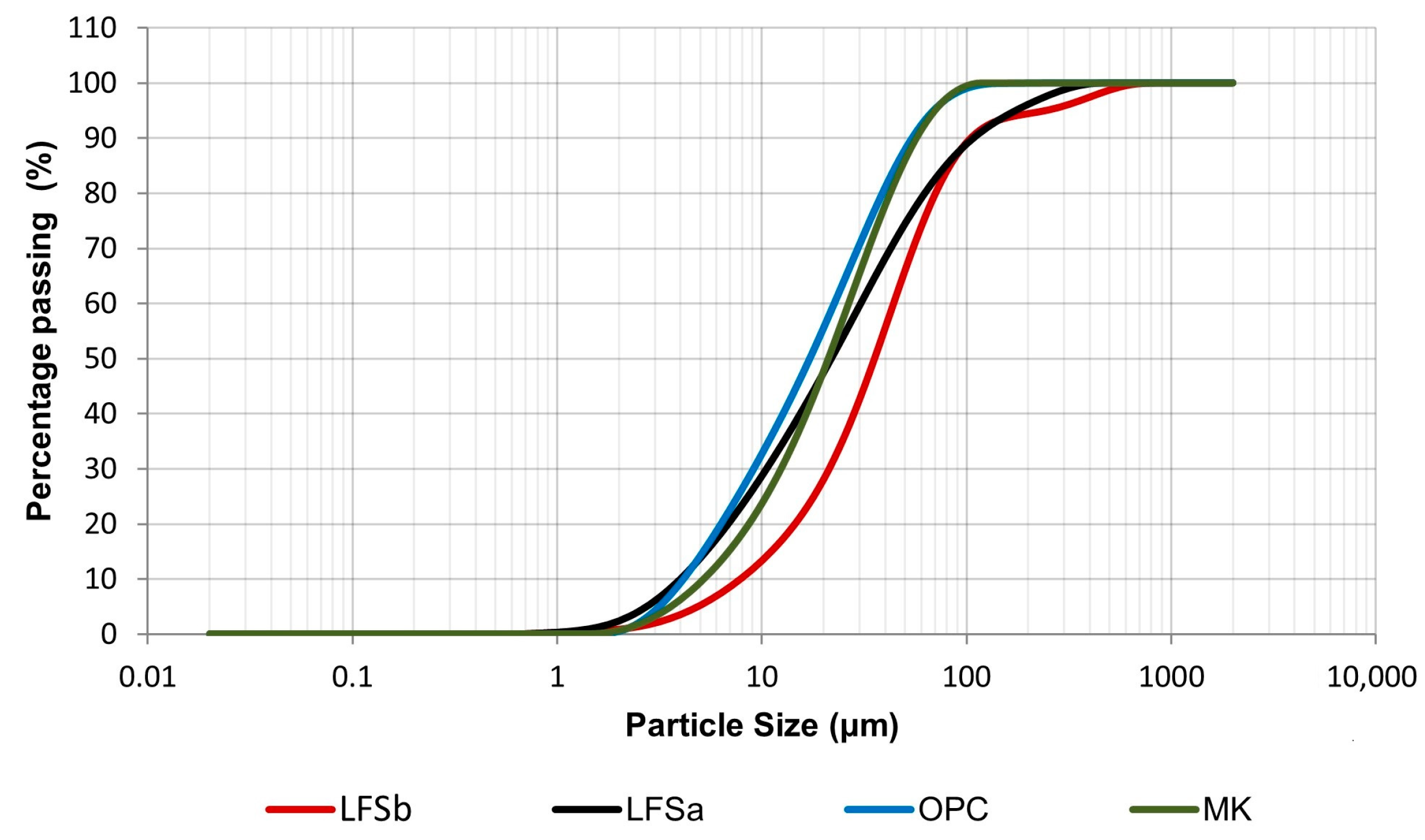
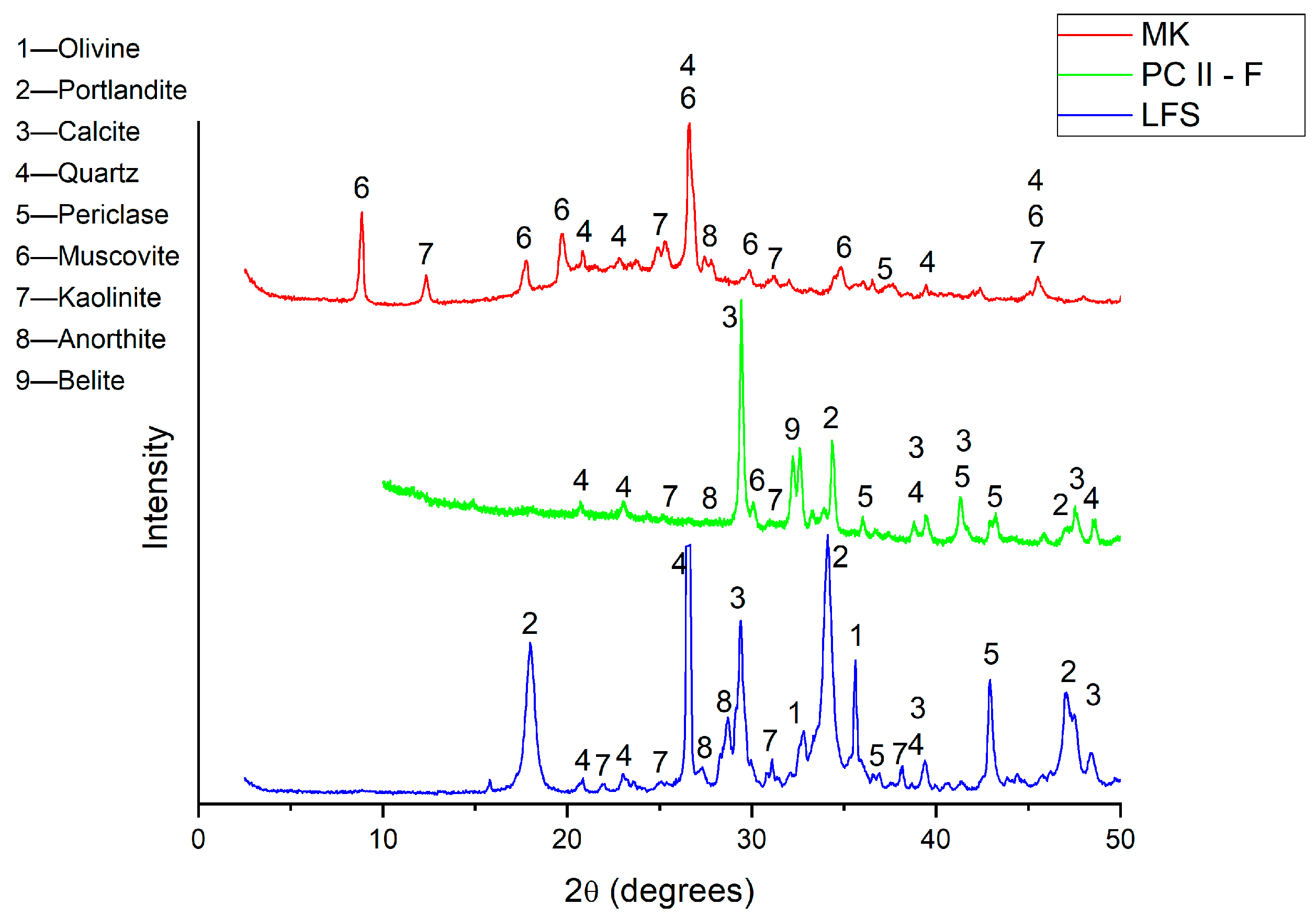
2.1. Characterization of the Materials

The LFS sample utilized in this study underwent a slow air-cooling process. Upon receipt, it was dried in an oven at 105 (±5) °C for 24 h. Subsequent checks confirmed its dryness by verifying the weight stability. Following this, an analysis of the particle size distribution of the LFS before processing (denoted as LFSb) revealed that the raw LFS did not possess desirable characteristics for the direct replacement of OPC, mainly due to its granulometry. This highlighted the necessity for processing, which was conducted using a method outlined in previous research [10,13], schematically depicted in Figure 1.
A 30-mesh sieve with a 0.6 mm opening was utilized. Subsequently, the fraction that passed through was subjected to ball milling. The grinding occurred in cycles with 400 (±2) g of LFS for 10 min at a fixed speed of 200 (±2) r.p.m. A Marconi® MA500 ball mill was used, equipped with a 1 L alumina ceramic jar and 40 ceramic balls, each 20 mm in diameter. Following this process, the processed LFS (denoted as LFSa) exhibited a particle size distribution curve that closely resembled that of OPC, as shown in Figure 2. Preliminary ball milling of the as-received LFS samples aimed at effectively reducing the particle size, a goal supported by the results for D50 values of both LFSb and LFSa (35.49 (±3) μm and 21.83 (±2) μm, respectively). The non-uniform granulometric shape of the curve indicates improved grain distribution.
The comparable particle size results among the LFS, OPC, and MK are primarily seen in their D10 values (4.00 μm, 4.14 μm, and 5.20 μm, respectively) and D50 values (21.83 μm, 17.14 μm, and 21.11 μm, respectively). These granulometry comparisons are acceptable and similar to the findings reported by Fang et al. [31].
The OPC used in this research was an ordinary Brazilian Portland cement, designated as CP II-F (equivalent to ASTM Type IL) [32,33], due to its inclusion of an inert limestone filler, leaving only the LFS as a reactive powder besides clinker. The MK sample used was from a stabilized and commercial batch.
The bulk density was 2.75 g/cm3 for the LFS, while it was 3.00 g/cm3 for the OPC and 2.50 g/cm3 for the MK. Choi and Kim [12] have found values of 2.97 and 3.16 g/cm3 for the LFS samples, and it is noted that this similarity is indicated when a part of the OPC is replaced with the LFS to ensure density and adequate rheology in the mixtures assessed [7,34]. The quartz sand (QS) had a fineness modulus of 1.16 and a maximum size of 0.6 mm. The used sample presented a density of 2.65 g/cm3.
X-ray fluorescence (XRF) analysis was conducted to determine the chemical composition of the ordinary Portland cement (OPC), limestone filler (LFS), and metakaolin (MK). The samples were prepared using the STD-1 (standardless) calibration, which allows for the analysis of chemical elements ranging from fluorine to uranium. The XRF measurements were carried out using a Zetium model X-ray fluorescence spectrometer (Malvern Panalytical). Additionally, loss on ignition (LOI) analysis was performed at 1200 (±10) °C for 2 h to evaluate the thermal stability of the samples.
Table 1 shows the resulting chemical composition obtained using XRF in a triplicate examination. These values correspond with those of the compounds used in the proposed mixture ratios. As anticipated, the LFS batch exhibited a high CaO content with equalized levels of the other four constituents (i.e., between 6% and 9%). In contrast, the MK sample was predominantly composed of approximately ~50% SiO2 and 36% Al2O3 (in wt.%).
The LFS content comprises a total of 72% when considering calcium oxide (CaO), silicon dioxide (SiO2), and iron oxide (Fe2O3), indicating reasonable chemical compatibility with the OPC used (79.66%). Regarding the LOI test, the LFS showed a result of 12%, similar to the sample studied by Xu and Yi [35]. Although similar LFS samples are used in the aforementioned studies, the reported CaO content is noticeably lower (48.1% to 40.2%) than that found in the present investigation. This difference may be attributed to the raw materials used in steel production (heterogeneous batches of scrap). Moreover, the cooling method adopted also significantly affects the chemical composition of the LFS, as previously reported [12,13,31,36]. Importantly, previous studies have used LFS samples with a higher SiO2 content (24.5% to 36.8%), which favors its direct replacement of OPC with greater C-S-H formation without the addition of pozzolanic material [10,12].
The ratio of oxide contents, used to compare LFS with OPC, is determined by a cementation index (CI) calculated from the oxide contents obtained via XRF analysis, as described in Equation (1) [37]:
C I   =   2.8   S i O 2   +   1.1   A l 2 O 3   +   0.7   F e 2 O 3 C a O   +   1.4   M g O
Based on this, the LFS and OPC samples have CI values of 0.54 and 0.60, respectively. According to the classification scale, both materials are considered moderately cementitious, ranging between 0.50 and 0.70, as also indicated as a hydraulic lime [37].
A PANalytical X’Pert diffractometer (X’Pert model, Malvern, Worcestershire, UK) was used to identify the corresponding crystal phases of the examined materials. The measurements were conducted at 40 kV and 30 mA using Cu Kα radiation with a wavelength of 0.15406 nm. To ensure reproducibility, a minimum of three representative samples were examined. The resulting X-ray diffraction (XRD) patterns were plotted using Origin Microcal® software (version 2018) and subsequently analyzed. Figure 3 displays the XRD patterns of the initial MK, OPC, and LFS samples, which are corroborated by the corresponding XRF data, as shown in Table 1.
The primary oxides in the LFS sample combine to form compounds such as portlandite (Ca(OH)2), olivine (Ca2(SiO4)), calcite (CaCO3), quartz (SiO2), and periclase (MgO). Additionally, there are small intensity peaks of kaolinite (Al2O3·2SiO2·2H2O). This pattern is consistent with those reported by Fang et al. [31], Araos Henríquez et al. [34], and Araos et al. [38]. Peaks corresponding to anorthite (CaO·Al2O3·SiO2) are also observed in both the MK and LFS samples. Anorthite is a mineral commonly found in the LFS samples described in the literature [7], which is created during reactions between the kaolin (Al2O3·2SiO2·2H2O) and CaCO3 at high temperatures. At this temperature, water is vaporized and CaCO3 decomposes into CaO and CO2, as described in Equation (2).
3Al2O3·2SiO2 + 3CaO + 4SiO2 → 3(CaO·Al2O3·2SiO2)
The high Al2O3 and SiO2 contents in MK favor anorthite formation [21]. This is also observed in the LFS due to the scrap used as input and the steelmaking/refining process, during the desulfurizing where the deoxidation agents (commonly silica and alumina) are added and incorporated into the slag [14]. Most minerals detected in this LFS are also commonly found in OPC, confirming their chemical similarity and binding properties. The presence of free silica and calcium oxide results in a lower alumina content. The formation of these compounds is thermodynamically possible at high temperatures during the slag production, as previously described in Equation (2).
To observe the initial particles and the resulting microstructural arrangements, a TESCAN® VEGA3 scanning electron microscope (SEM) (Brno, Czech Republic) was used in combination with an energy-dispersive X-ray (EDX) detector. Figure 4 shows a typical SEM image of preprocessed LFS particles, clearly displaying heterogeneous particles in both shape and size, even after sieving and grinding. This can be explained by the chemical reactions of expansive hydration and subsequent disintegration of these particles (crystalline compounds), resulting in smaller ones [39]. This process occurs during the slow cooling of the slag.

2.2. Analysis of the Mortars

The reference mix (control mortar, designated as REF) was produced using a 1:3 (OPC) mass ratio. Subsequently, three mixtures were prepared to test the substitutions of 30% OPC with LFS and 10% with MK, with the third mixture specifically designed to understand the interaction between LFS and MK in the OPC substitution. The substitution of 30% OPC with LFS was based on previous research, which indicates that this limit prevents the detrimental volumetric expansion of the mortars and ensures the stability of the cementitious materials [13,39]. This value is still considered viable for cement substitution. Table 2 depicts the proposed mortar mixtures, which were designed to achieve the optimal chemical interaction. The water/binder ratio was adjusted to ensure normal consistency according to the flow table test, aiming for a spread of 260 (±5) mm, as recommended by the NBR 13276 standard [40]. The 1:3 (OPC–sand) mass ratio was used for the cement mortars considering the ASTM C109 standard [41] to minimize interference from other binders, such as hydrated lime.
After casting, the mortar specimens were demolded after 48 h and subsequently cured under controlled conditions of 23 (±2) °C and 60 (±5) % humidity up to 28 and 180 days. The properties evaluated for the examined mortars are described in Table 3.
The curing times of 28 and 180 days were determined based on the different hydration processes in the ternary mixture of LFS, MK, and OPC. The 28-day period is a standard benchmark for early strength and initial hydration, widely used to assess short-term performance. In contrast, the 180-day period accommodates the slower reactions of LFS, as observed by Václavík et al. [42], allowing for a thorough evaluation of long-term effects, including mechanical development, microstructural changes, and material durability.
Table 3. The properties examined correlated with quantity of specimens, dimensions, and standards adopted.
TestNo. of SpecimensDimension (*)Standard
Fresh stateConsistence NBR 13276 [40]
Water retention NBR 13277 [43]
Entrained air content NBR 13278 [44]
Density NBR 13278 [44]
Hardened StateFlexural strength (Fs)340 × 40 × 160NBR 13279 [45]
Compressive strength (Cs)340 × 40 × 160NBR 13279 [45]
Apparent density340 × 40 × 160NBR 13280 [46]
Water absorption by capillarity340 × 40 × 160NBR 15259 [47]
Dynamic modulus of elasticity340 × 40 × 160NBR 15630 [48]
Volumetric stability325 × 25 × 285NBR 15261 [49]
(*) dimensions are in mm.
The water retention was determined according to the Brazilian standard NBR 13277 [43], which is specific for determining water retention in mortars. The test was conducted by measuring the amount of water mass retained in the mortar after a suction process using a low-pressure vacuum pump and a filter funnel. The test execution follows the same principles as ASTM C110-20 [50], which deals with water retention in hydrated lime; however, the Brazilian standard evaluates based on mass variation, while the American standard evaluates based on flow.
The evaluation of the entrained air content in mortars was performed by determining the density of the mortars. For this, a cylindrical container was used, which was initially weighed (mv) and filled with distilled water of a determined volume (vr). The procedure involved filling the cylindrical container in three layers of approximately equal height. Each layer was compacted with 20 strokes along the perimeter using a spatula. After compaction, the container was dropped three times from a height of approximately 3 cm to remove voids between the mortar and the container wall. The mortar surface was then leveled with the spatula in two orthogonal passes. Finally, any particles or water adhering to the container’s outer wall were removed, and the mold with the mortar was weighed to record the total mass (mc). The data obtained were used to calculate the density and the entrained air content of the mortars using Equations (3) and (4) [44]. It is important to highlight that it is also necessary to know the theoretical density of the mortar without voids (dt).
d = m c m v v r ×   1000
A   =   100   ×   ( 1   d D t )
The tests on the hardened state were conducted under laboratory ambient conditions with a temperature of 20 (±2) °C and 40% (±5) humidity. For these tests, prismatic specimens measuring 40 × 40 × 160 mm were prepared. For the flexural strength test, the specimens were subjected to a loading rate of 50 N/s at the center, with the beams supported at each end, and the final value was the average of three readings. After failure, the halves were tested for compressive strength, ensuring they were free from chips or other defects, as recommended by ASTM C349-14 [51]. The loading rate for the compressive test was established at 500 N/s, with the result being the average of six readings. An EMIC® testing machine was used for both tests.
The test for determining water absorption by capillarity and the capillarity coefficient was conducted by drying the samples in an oven at 105 °C for 24 h and weighing them in the dry state. Subsequently, the specimens were placed in a container with a constant water level maintained at 5 (±1) mm from their bases. They were weighed after 10 and 90 min of contact with the water. Equation (5) represents the total water absorption by capillarity (At, in g/cm2), where m90 is the mass of the specimen after 90 min (in g), m0 is the initial mass (in g), and a is the cross-sectional area of the specimen (in cm2) [47].
A t = m 90 m 0 a
The capillarity coefficient is the slope of the line through the water absorption values at 10 and 90 min, with time as the x-axis (square root) and water absorption as the y-axis. It is approximately equal to the average difference in mass at 10 and 90 min [47].
It is important to remark that among the standards to measure the dynamic modulus of elasticity of cementitious materials, only the Brazilian one specifically addresses the evaluation of mortars, and this standard is an adaptation of ASTM C215-14 [52]. Therefore, the results were obtained through ultrasonic pulse velocity (UPV) measurements using USLab® equipment (Agricef, Paulínia, Brazil).
For mineralogical characterization using X-ray diffraction (XRD), the mortar samples were ground in a porcelain mortar and neutralized in acetone. The material was then filtered, and the retained material was dried at 40 °C for 30 min. After this period, the material was sieved through a 125 μm mesh and placed in a microtube (Eppendorf type). For the XRD analysis, an X′Pert Panalytical diffractometer in Bragg–Brentano geometry was used, equipped with Cu Kα radiation, a Ni filter, and a wavelength of 0.15406 nm.
To obtain images via scanning electron microscopy (SEM), the extracted samples were fractured into fragments with edges up to 1 cm and subjected to a reaction neutralization procedure at the specified ages (28 and 180 days). After this process, the samples were dried in an oven at 40 °C for 24 h, then embedded in acrylic resin for grinding and polishing and coated with carbon. Imaging was performed using a TESCAN® VEGA3 scanning electron microscope (SEM) (Brno, Czech Republic) in combination with an energy-dispersive X-ray (EDX) detector.

3. Results and Discussion

3.1. Performance Properties of Mortars in the Fresh State

Table 4 shows the experimental density, entrained air content, and water retention results of the assessed mortar samples. The highest densities are those obtained when the REF and OPC + MK samples were considered. The REF and OPC + LFS samples showed very similar water/binder ratios of 0.63 and 0.64, respectively. The mixtures with the MK content demonstrated similar behavior. A slight difference in the water/binder ratio was observed when the MK-containing samples were compared with those without MK additions. Additionally, the verified water retention results were of the same order of magnitude.
The analysis of the effect of the LFS on the resulting fresh-state samples showed a slight decrease in the mass densities (i.e., from 2153 to 2083 kg/m3), even with a 30% replacement of OPC with LFS. This reduction is associated with the lower density of the LFS (2.75 g/cm3) compared to the OPC (3.00 g/cm3). The entrained air results were of the same order of magnitude as the REF and OPC + MK mixtures, increasing only in the OPC + LFS mixture (5%). In the OPC + LFS + MK mixture, this factor matched the mixes without slag. The water retention slightly decreased in the OPC + MK mixture. The LFS-containing mixes exhibited contrasting behavior, with the OPC + LFS + MK mixture not only increasing this index but also achieving the highest percentage (~84%). Since both the LFS and MK replaced OPC content, the observed increase seems to be associated with the high water portion demanded to coat or to cover the particles. Borges Marinho et al. [10] replaced hydrated lime with LFS, resulting in lower water retention in the LFS mixtures without pozzolanic additives.

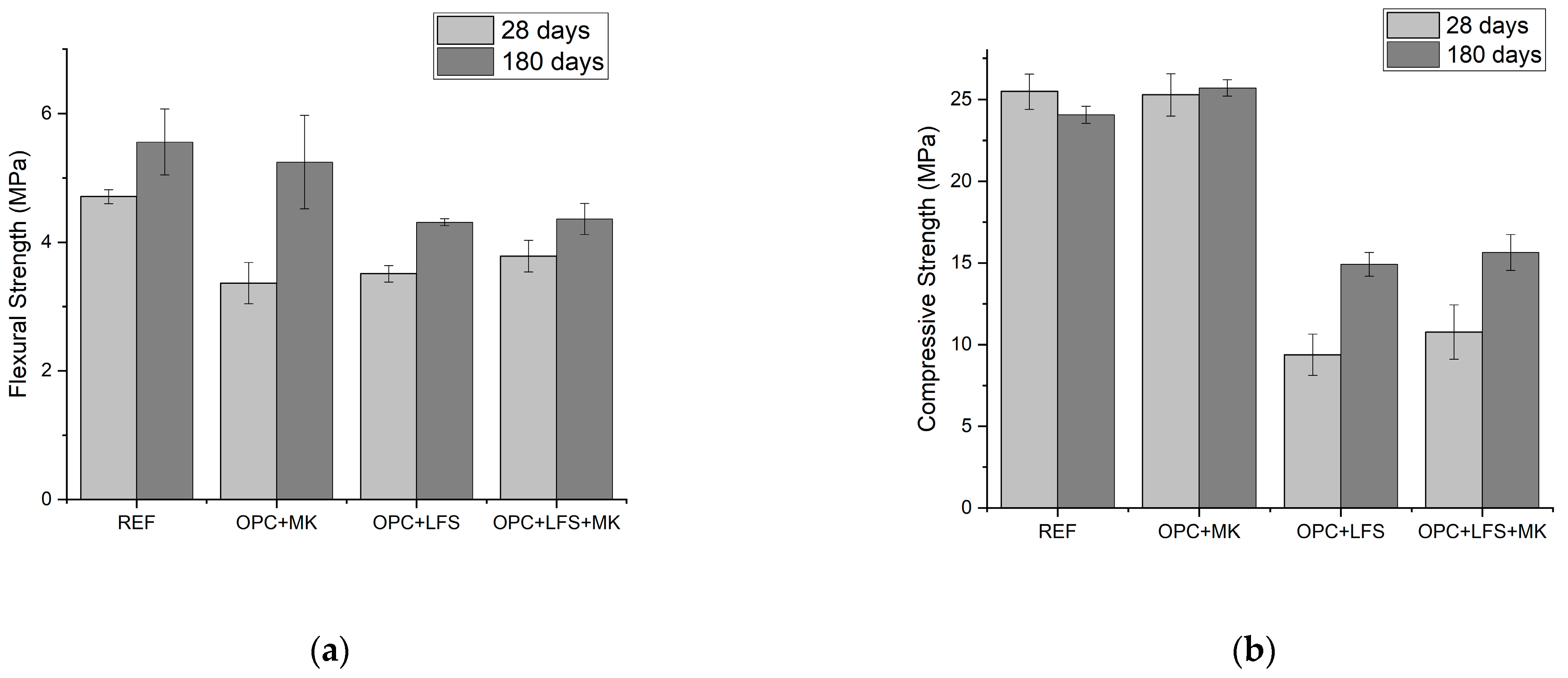
3.2. Mechanical Properties of Mortars

Table 5 and Figure 5 summarize the experimental results of the mechanical properties (flexural and compressive strengths) of the evaluated mortars, with letters indicating homogeneous groups (HGs). The corresponding mechanical responses are highlighted through comparisons.
Considering the LFS-containing mixtures, with 30% of OPC replaced, the compressive strength (CS) at 28 days decreased by about 2.7 times, when compared to the REF sample. At 180 days, however, the OPC + LFS samples demonstrated an increase in the CS of about 1.6 times (~15 MPa) when compared with the results at 28 days (~9 MPa). The flexural strengths (FSs) are of the same order of magnitude among the examined samples at 28 days, except the REF mixture, which showed an FS about 35% higher than the other examined mixtures.
The MK-containing mortars at 28 days indicated that this curing period was insufficient to provide pozzolanic chemical reactions, and similar was also observed for the OPC + MK mixture. However, the REF mortar with added MK showed a substantial (~54%) increase in the FS results when comparing the curing times of 28 and 180 days. This demonstrates that the MK addition increases the FS only for those samples without the LFS content.
The OPC + LFS + MK sample showed a ~1.5× lower CS at 28 days of curing compared to that obtained at 180 days (~16 MPa). Importantly, the OPC + LFS + MK sample had a 42% lower cement consumption compared to the REF sample. Another significant result concerns the FS corresponding to the LFS-containing mixtures achieved at 180 days. The OPC + LFS and OPC + LFS + MK samples have an increased FS of about 23% and 15%, respectively.
The observed mechanical behavior at 28 days is explained by the increased porosity, despite the pore refinement, due to MK addition, as previously reported [26]. The high compressive strength (particularly at 180 days) suggests its possible use in structural masonry.
Herrero et al. [8] verified that LFS addition decreases the CS, while flexural strength is maintained. This is attributed to the greater distribution of the chemical compounds formed during the binder hydration and to the lower proportion of C-S-H, when compared to the reference mortar (REF and OPC + MK, respectively). Such behavior seems to be associated with belite hydration. This compound originates from larnite (βC2S) in the slow air-cooling stage, causing internal tensions in the grains and consequent breakage processes. This provides a higher fineness level to the bulk material. In the cementitious application, the component returns to its first phase through the hydration mechanism, and it is responsible for the resulting matrix strength. This occurs mainly at advanced ages of curing. In conventional cementitious matrices, belite is the predominant constituent due to its high concentration in OPC composition, but its amount in the LFS samples is variable, which affects its binding potential [7,36,53].

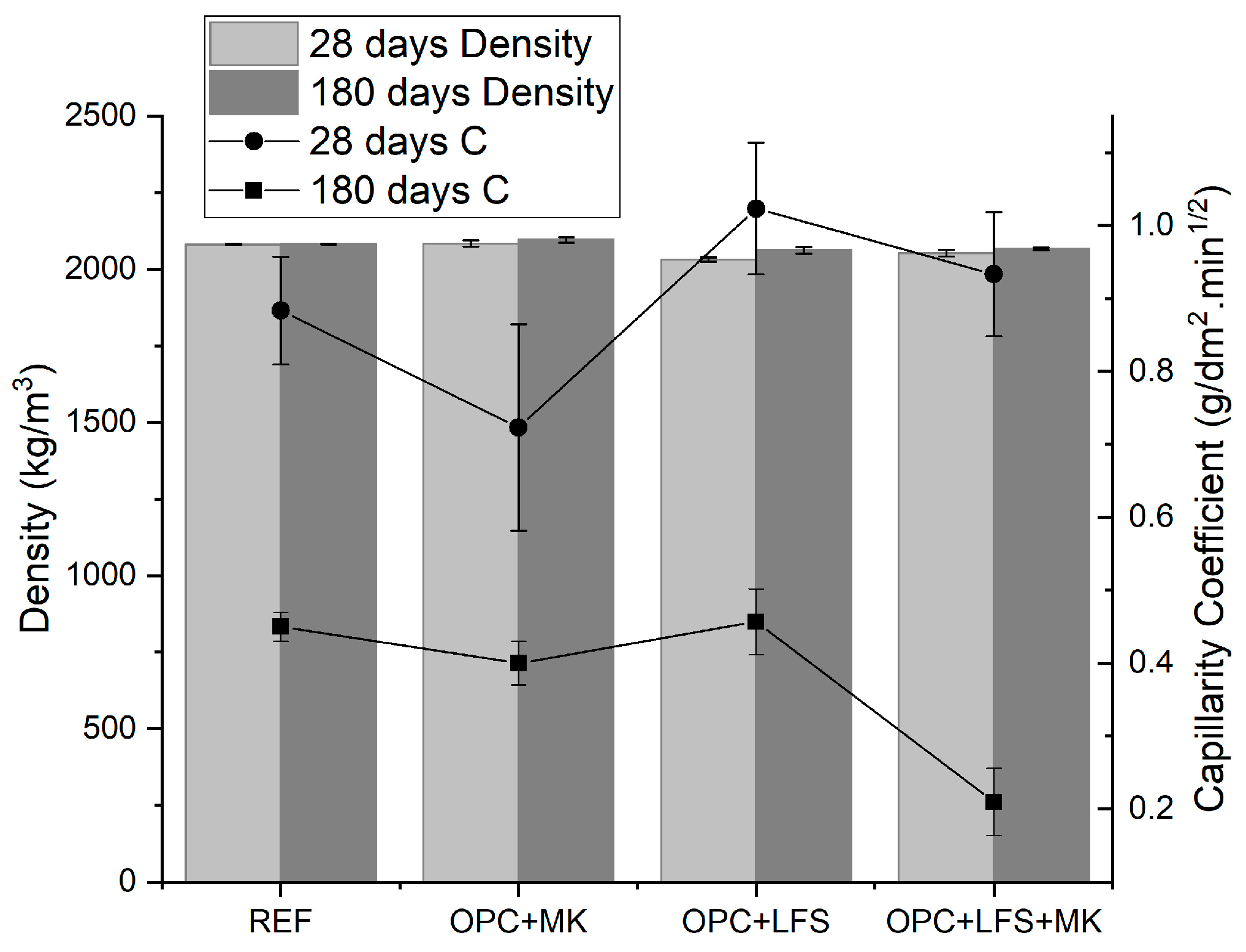
3.3. Performance Properties of Mortars in the Hardened State

Table 6 and Figure 6 show the experimental results of the dynamic modulus of elasticity (Ed), the water capillarity coefficient (C), and the apparent density in the hardened state for all mortars examined. Additionally, Figure 6 depicts a correlation between the capillarity coefficient and apparent density of the examined samples.
When the results of the dynamic modulus of elasticity (Ed) of the REF and OPC + MK samples were compared with the OPC + LFS and OPC + LFS + MK samples, reductions of 35% and 22% were observed, respectively. This indicates an increase in the porosity and pore refinement, which is consistent with previous investigations involving MK [21,26]. The aforementioned behavior imparts less rigidity to the cement matrix. The decrease in the Ed results of the mortars with LFS demonstrates an improvement, as lower Ed values indicate a greater capacity to absorb deformations [54]. The mortars with high rigidity are prone to microcracking under weather cycles such as thermal variations [55]. Further analysis reveals that the addition of MK affects the Ed results differently in the mortars without the LFS content. The pozzolanic additions typically reduce the action of harmful agents due to a more compact microstructure provided. This corroborates the higher Ed values observed when the MK-containing samples are considered [21,22]. However, this effect appears partially mitigated in the samples with slag content, as suggested by the results of the OPC + LFS and OPC + LFS + MK samples.
The MK content did not substantially modify the density in the hardened state of the mixtures examined, as shown in Table 5. The MK-containing mortars showed a slightly higher density than other mixtures, which is associated with a decreased porosity level, as also previously reported [26,56]. Both the capillary water absorption and the capillarity coefficient were affected by the MK addition. A more pronounced modification is associated with the LFS-containing mortars, as also demonstrated in Table 5. This behavior seems to be attributed to the improved pore size distribution, which enhances the stability of the cementitious matrix structure, as depicted in Figure 6. Importantly, the addition of LFS alone in cementitious mixes acts as a filler, directly influencing the matrix porosity and consequently the capillary coefficient.
The discrepancy between the higher flexural strength and lower compressive strength observed in samples containing LFS can be attributed to its structural characteristics, such as porosity and mechanical properties [10]. Adding LFS to the mortar increases its porosity, which can enhance adhesion and flexural strength but may reduce compressive strength due to its lower density and potentially insufficient filling effect, particularly at early ages [7,8]. Additionally, LFS affects the formation and distribution of hydration products, resulting in an initially lower compressive strength that improves with time.
Despite these differences, the mechanical properties of the mortars containing LFS exhibit similar trends across various mixes and curing durations. Both LFS-containing mixes showed lower strengths compared to those without LFS but demonstrated significant improvements when comparing performance at 180 days to 28 days, akin to the extended-age results observed by Manso et al. [9]. To provide a more comprehensive understanding, this study will include discussions on chemical and microstructural analyses to clarify how LFS influences mortar properties and explains the observed changes over time.

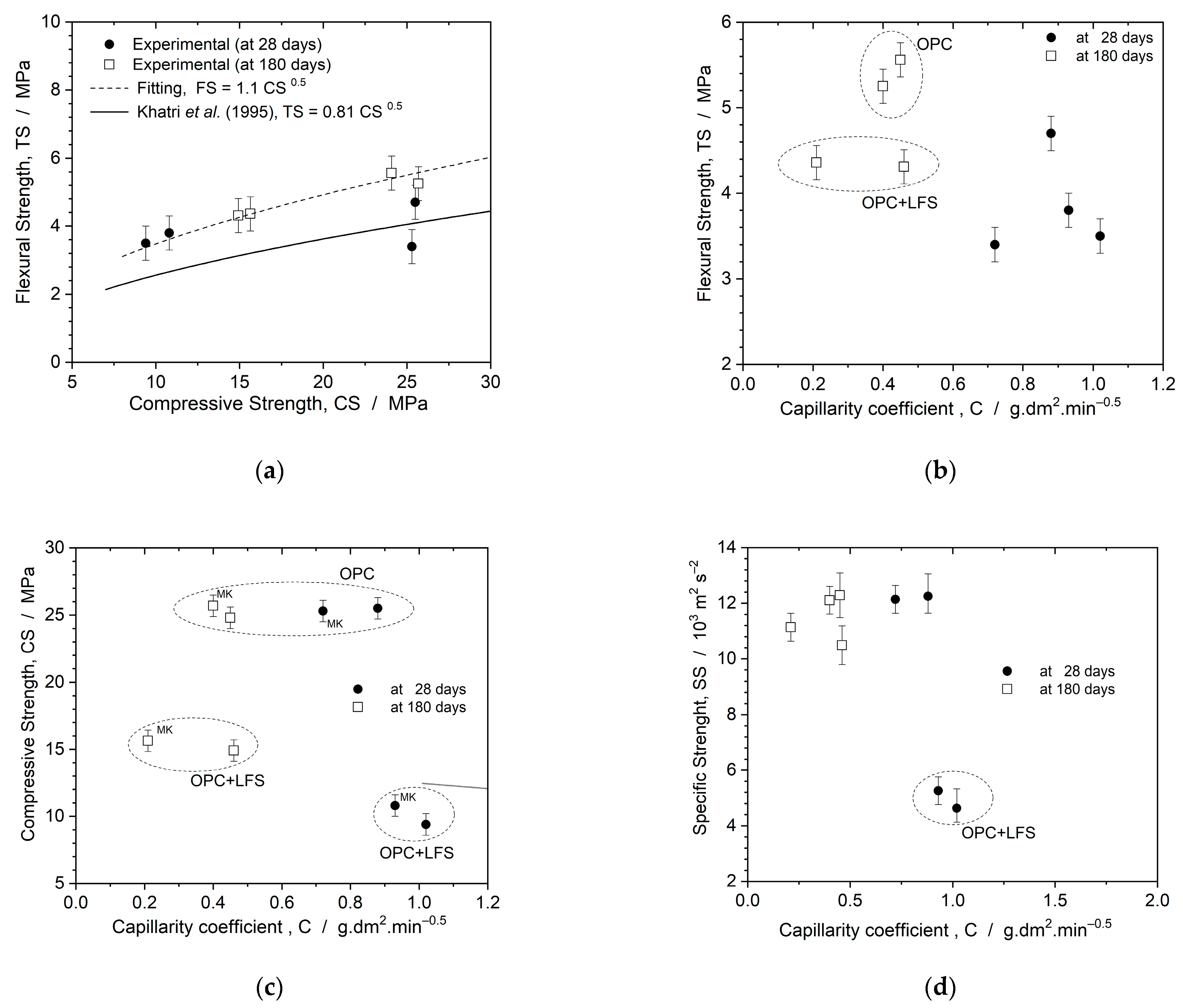
3.4. Correlation between Mechanical Properties and Capillarity Coefficient of Mortars

Figure 7a presents the experimental results of the flexural-to-compressive strength ratio, commonly evaluated for cementitious materials [57,58,59,60]. This ratio provides insights into the correlation between flexural strength (FS) and compressive strength (CS) throughout the curing period for each of the examined mortars. The equation FS = 1.1 CS0.5 fitted with a quality of R2 = 0.99 describes this relationship. While this equation overestimates the results for 28 days, the equation proposed by Khatri et al. [57], FS = 0.81 CS0.5, helps to delineate the range variation. Angelin et al. [58] found a similar ratio (same order of magnitude) in mortars modified with rubber particles, FS = 0.93 CS0.56. Conversely, Xavier et al. [59], studying distinctive self-compacting concrete, described the FS-to-CS ratio as FS = 0.65 CS0.5.
Figure 7b–d illustrate the resulting FS, CS, and specific strength (SS) as functions of the capillarity coefficient, respectively, for all mortars examined at 28 and 180 days. In a general way, the attained FS results are higher at 180 days than at 28 days. This is also associated with lower capillarity coefficients. It is remarked that the LFS-containing samples exhibited lower FSs than the LFS-free mixtures at 180 days. Similarly, the OPC + LFS + MK samples showed lower CS results than those containing only MK, as can be observed in Figure 7c. The SS parameters were determined by calculating CS values at 28 and 180 days, dividing by their corresponding densities. With this, the parameter SS indicates the strength-to-lightweight effect ratio. These values typically profile the CS trend. The lowest SS is that of the LFS-containing samples at 28 days, as shown in Figure 7d. Overall, the SS values suggest a similar range among the investigated mortars.

3.5. Microstructural and Mechanical Behavior Correlations

The XRD patterns of the four mortars after 180 days indicated the presence of hydration and pozzolanic reactions, as evidenced by specific crystallographic phases, as shown in Figure 8. The comparison of the XRD results revealed that the OPC + MK and OPC + LFS + MK samples exhibited reduced portlandite peaks at 180 days. This suggests portlandite consumption and the occurrence of pozzolanic reactions, potentially leading to the formation of calcite. Additionally, the peaks corresponding to anorthite of about 27° at the crystallographic plane (223) were more pronounced at 180 days when compared with at 28 days.
The REF and OPC + LFS samples also showed decreased portlandite peaks at 180 days. Similar to the MK-containing samples, the peaks corresponding with the anorthite at approximately 27.5° were slightly more prominent at 180 days compared to those at ~28.5°, as indicated by R04059.1. These anorthite peaks were also observed in the initial materials (Figure 3). At 28 days, the peaks corresponding with the anorthite phase appeared predominantly at 28.5° (the highest intensity peak, R04059.1), while at 180 days, they shifted to 27.5° (the second most intense peak).
However, the observed mechanical responses cannot be solely attributed to the anorthite peaks. They are also influenced by various other factors, including the consumption of portlandite (evidenced by reduced peaks) through all mortar samples when comparing XRD patterns at 28 and 180 days. Further analysis of the resulting microstructural arrangements suggests a more compact paste and a less porous structure. Additionally, a better integration between sand particles and the paste was also noted.
Microstructural analysis revealed a strong correlation between the mechanical properties and interactions with the mortar components. Figure 9a–h, obtained from mortars at 28 and 180 days, illustrate compacted mortars after 180 days, all at the same magnification (500×). Considering the curing times, the microstructure of the REF mortar showed minimal alterations at the aggregate–paste interface, with a reduction in the number and size of voids, as shown in Figure 9a,e. In contrast, the OPC + MK mortar mixture exhibited significant changes after 180 days, which provided a pore-free structure and improved sand integration by the paste, as shown in Figure 9e.
The comparison of the resulting micrographs shown in the SEM images of both the OPC + LFS and OPC + LFS + MK mortars revealed substantial improvements in paste homogeneity, with fewer voids and better aggregate grain integration than other ones. This microstructure is similar to that of the REF and OPC + MK mixtures. However, the mortars with LFS maintained similar microstructures even with lower OPC consumption. This suggests that, despite the reduced compressive strength, the durability of these mortars with LFS is higher due to the filler effect and the higher amount of C-S-H than other ones. This is confirmed by the similar flexural strength between the OPC + MK and the OPC + LFS mortars (Figure 5). It is worth noting that the MK content in the mortar with LFS did not provide substantial microstructural modifications. Furthermore, the dynamic modulus of elasticity (Ed) exhibited a correlation with the capillarity coefficient, as this property decreases in proportion to the reduction in the Ed.
Comparing the SEM images of the REF mortars (Figure 9a,e) with the OPC + LFS mortars (Figure 9c,g), it is observed that the latter samples exhibit lower porosity. The morphology of the OPC + LFS mortar is associated with higher concentrations of CaO and Ca(OH)2, typically deposited inside paste pores. Some of these oxides have not completely reacted with OPC or MK components, and a pore refinement is achieved.
The comparison of SEM images of mortars at different curing ages underscores the importance of analyzing morphological evolution over time. The MK-containing samples showed voids at 28 days, which were absent at 180 days. This indicates ongoing reactions facilitated by the MK content throughout the curing process. The mixtures containing LFS demonstrate more uniformity in aggregate grain integration and filler effect. This seems to be attributed to the formation of C-S-H, as also reported by Singh et al. [18].
Figure 10 illustrates quasi-hexagonal plates of portlandite (Ca(OH)2) interspersed with C-S-H and small ettringite needles (magnification 3000×), confirming a substantial decrease in the attained quantity and pore sizes. This correlates with significant enhancements in mortar performance over longer curing times.
In general, the partial replacement of OPC with LFS improved the microstructure of the mortars due to the particle distribution and size (physical factors) and the formation of more stable chemical compounds. These findings align with those of other researchers who have also used slag as an SCM [5,61,62].

4. Conclusions

Based on the potential use of LFS as a supplementary cementitious material in mortars, along with OPC and MK, and the experimental results obtained after 28 and 180 days of curing, the following conclusions can be drawn:
  • Comparing the mechanical properties of the mortars with respect to curing time, it is evident that the extended curing period (180 days) significantly influenced the mixtures containing LFS (OPC + LFS and OPC + LFS + MK). After 180 days, the compressive strength of the OPC + LFS + MK mixture showed a substantial 44% increase. Additionally, the longer curing time had a greater impact on the compressive strength and dynamic modulus of elasticity (Ed) than on the flexural strength, suggesting that MK was more effective in improving the microstructure rather than the mechanical behavior of the mortars. Prolonged curing is essential for the full development of belite hydration (LFS) and pozzolanic reactions (MK), which are key to realizing the enhanced properties of OPC + LFS + MK blends.
  • Analysis of the chemical compounds in the mortar samples using X-ray diffraction (XRD) showed that the extended curing time (180 days) resulted in a substantial reduction in Ca(OH)2 and the formation of anorthite. This reduction is attributed to the consumption of Ca(OH)2 by pozzolanic reactions, which also leads to the formation of C-S-H (calcium silicate hydrate) compounds.
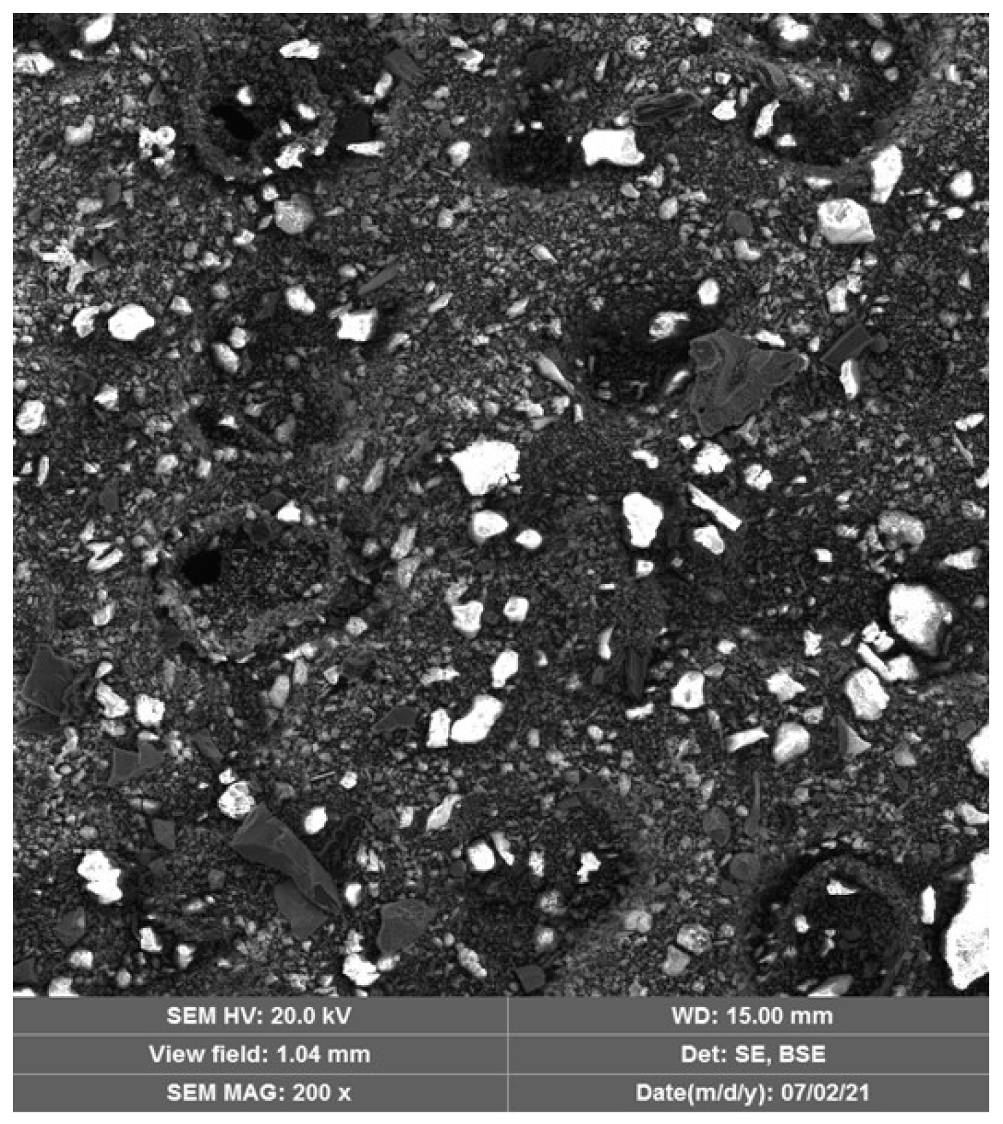
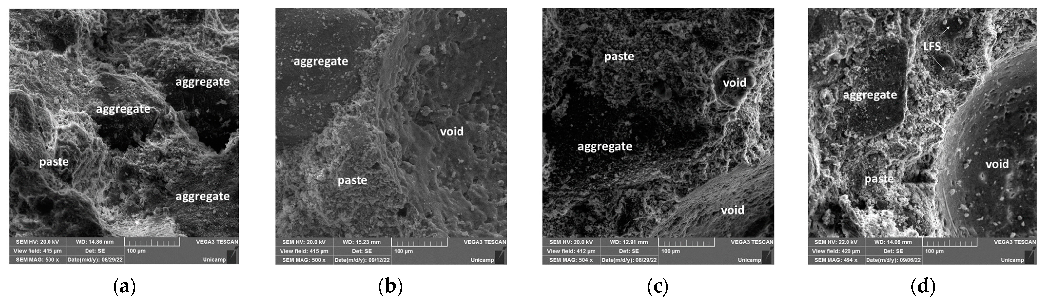
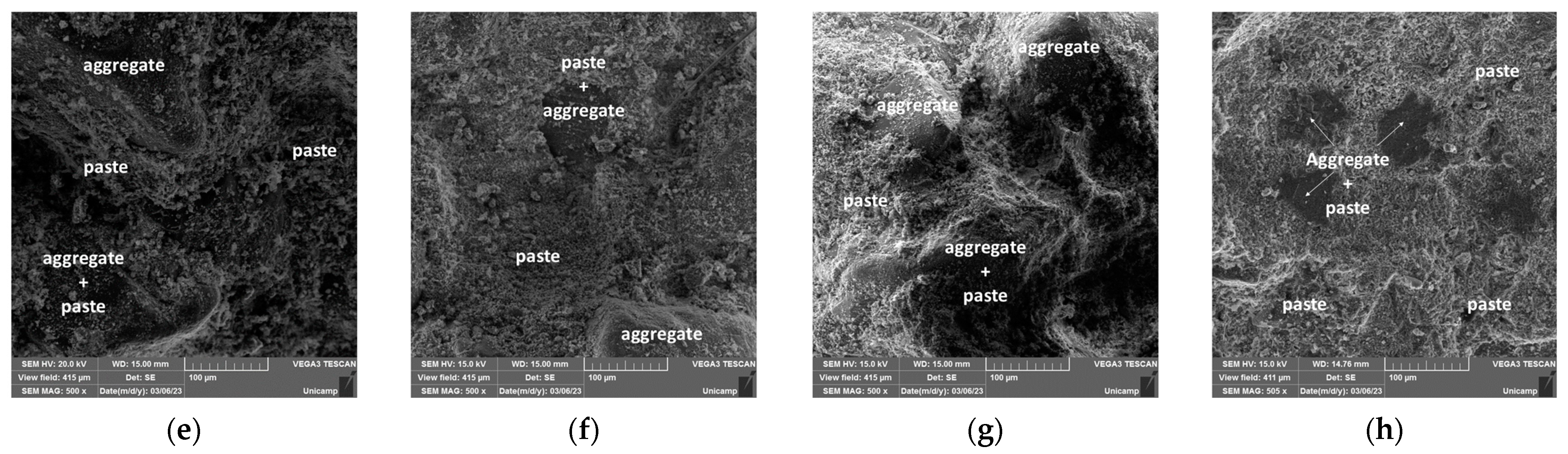
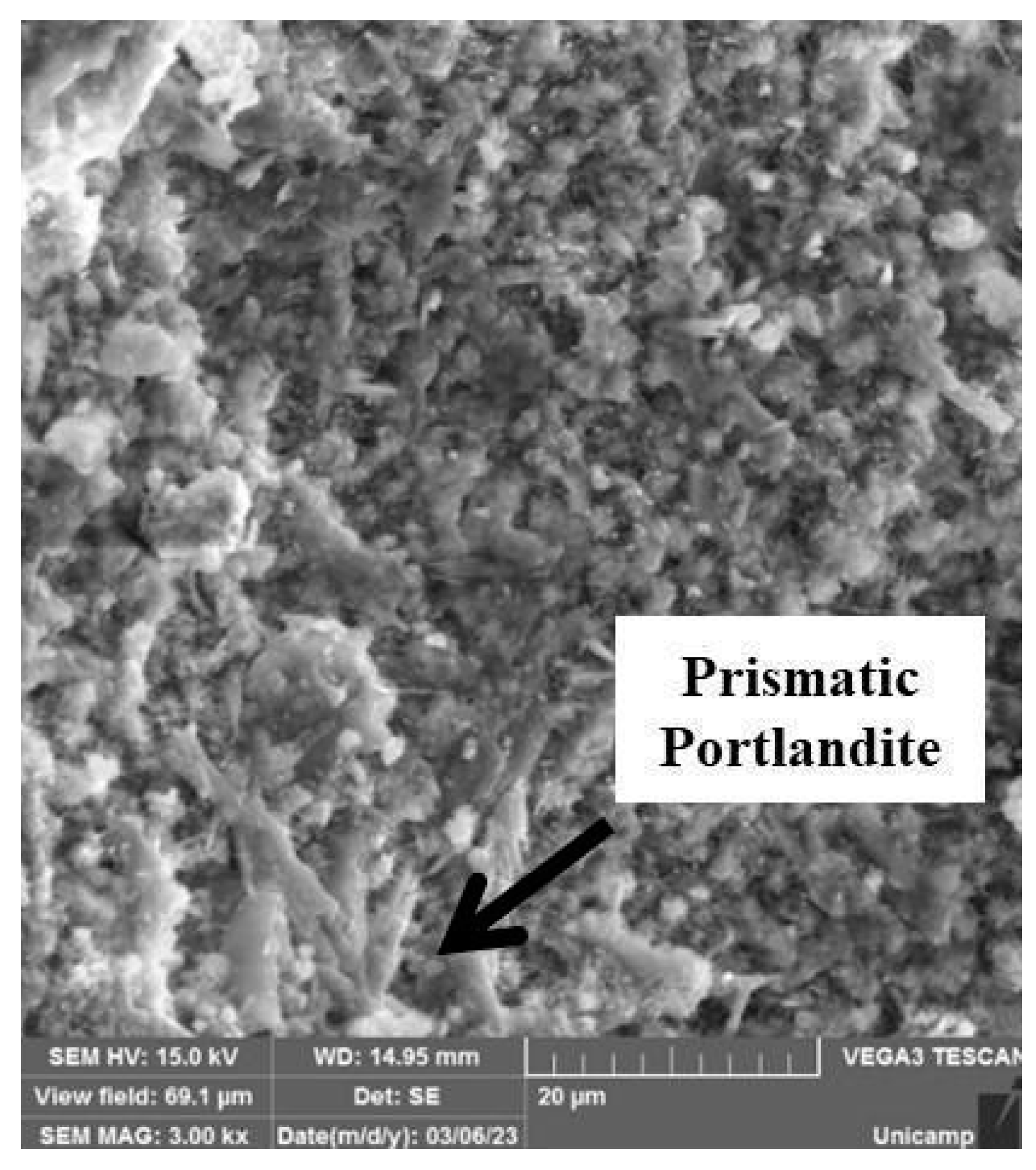
  • Scanning electron microscopy (SEM) images confirmed the XRD findings, showing a significant reduction in the porosity of the mortars when comparing 28 and 180 days of curing. This effect was most pronounced in the OPC + LFS and OPC + LFS + MK mortars. The improved microstructure is due to the filler effect and the formation of additional chemical compounds (C-S-H and C-A-S-H) from the combined presence of LFS and MK, as evidenced by the increased encapsulation of sand grains by the cement paste. This behavior is also indicated by the lower capillarity coefficients and higher stiffness (>Ed) at 180 days. The filling effect provided by both LFS and MK contributes to better microstructural stability.
  • The combined effect of the OPC + LFS + MK blend not only enhances the mechanical properties and microstructure of the mortars after 180 days of curing but also reduces OPC consumption by 42% compared to the reference mixture. This reduction leads to significant cost savings, as cement is a major expense in construction. Environmentally, using MK and LFS reduces the demand for OPC, thus lowering the carbon footprint and supporting circular economy principles. By incorporating industrial by-products and reducing waste, this approach promotes more sustainable and efficient resource use in construction.
  • For future studies, it is recommended to explore the effects of combining LFS with other pozzolans and to conduct durability analyses. Additionally, evaluating the environmental and economic parameters of using LFS as a supplementary cementitious material in mortars should be considered.

Author Contributions

Conceptualization, T.S. and G.F.; methodology, T.S. and G.F.; software, T.S., G.F., E.S., E.M. and W.R.O.; validation, T.S. and G.F.; formal analysis, T.S., G.F. and W.R.O.; investigation, T.S., G.F., E.S. and E.M.; resources, T.S. and G.F.; data curation, T.S. and G.F.; writing—original draft preparation, T.S., G.F., E.S., E.M. and W.R.O.; writing—review and editing, G.F.; visualization, T.S. and G.F.; supervision, G.F.; project administration, G.F.; funding acquisition, G.F. All authors have read and agreed to the published version of the manuscript.

Funding

This research was funded by Coordination for the Improvement of Higher Education Personnel (CAPES), financial code 001.

Data Availability Statement

The data are not publicly available and can be provided upon request.

Acknowledgments

The authors would like to thank ArcelorMittal for donating the ladle furnace slag sample and Votorantim Cimentos for providing the batch of ordinary Portland cement. We also extend our gratitude to CAPES, the Multi-User Scanning Electron Microscopy Laboratory, and the PPGEC FECFAU and FT/UNICAMP for their support.

Conflicts of Interest

The authors declare no conflicts of interest.

References

  1. WorldSteel Association. Total Production of Crude Steel. 2023. Available online: https://worldsteel.org/data/annual-production-steel-data/ (accessed on 20 July 2024).
  2. Maghool, F.; Arulrajah, A.; Du, Y.J.; Horpibulsuk, S.; Chinkulkijniwat, A. Environmental impacts of utilizing waste steel slag aggregates as recycled road construction materials. Clean. Technol. Environ. Policy 2017, 19, 949–958. [Google Scholar] [CrossRef]
  3. Jin, F. Sustainable utilization of slags. In Low Carbon Stabilization and Solidification of Hazardous Wastes; Elsevier: Amsterdam, The Netherlands, 2021; pp. 321–341. [Google Scholar]
  4. Martins, A.C.P.; Franco de Carvalho, J.M.; Costa, L.C.B.; Andrade, H.D.; de Melo, T.V.; Ribeiro, J.C.L.; Pedroti, L.G.; Peixoto, R.A.F. Steel slags in cement-based composites: An ultimate review on characterization, applications and performance. Constr. Build. Mater. 2021, 291, 123265. [Google Scholar] [CrossRef]
  5. López-Ausín, V.; Revilla-Cuesta, V.; Skaf, M.; Ortega-López, V. Mechanical properties of sustainable concrete containing powdery ladle furnace slag from different sources. Powder Technol. 2024, 434, 119396. [Google Scholar] [CrossRef]
  6. Sideris, K.K.; Tassos, C.; Chatzopoulos, A. Production of durable self-compacting concrete using ladle furnace slag (LFS) as filler material. Procedia Eng. 2015, 108, 592–597. [Google Scholar] [CrossRef]
  7. Najm, O.; El-Hassan, H.; El-Dieb, A. Ladle slag characteristics and use in mortar and concrete: A comprehensive review. J. Clean. Prod. 2021, 288, 125584. [Google Scholar] [CrossRef]
  8. Herrero, T.; Vegas, I.J.; Santamaría, A.; San-José, J.T.; Skaf, M. Effect of high-alumina ladle furnace slag as cement substitution in masonry mortars. Constr. Build. Mater. 2016, 123, 404–413. [Google Scholar] [CrossRef]
  9. Manso, J.M.; Rodriguez, Á.; Aragón, Á.; Gonzalez, J.J. The durability of masonry mortars made with ladle furnace slag. Constr. Build. Mater. 2011, 25, 3508–3519. [Google Scholar] [CrossRef]
  10. Borges Marinho, A.L.; Mol Santos, C.M.; de Carvalho, J.M.F.; Mendes, J.C.; Brigolini, G.J.; André Fiorotti Peixoto, R. Ladle Furnace Slag as Binder for Cement-Based Composites. J. Mater. Civ. Eng. 2017, 29, 04017207. [Google Scholar] [CrossRef]
  11. de Freitas Cordova de Souza, E.; da Silva, T.F.; de Castro, M.A.; dos Santos Ferreira, G.C. Combined Use of Ladle Furnace Slag and Rice Husk Ash as a Supplementary Cementitious Material. Mater. Res. 2023, 26 (Suppl. S1), e20230069. [Google Scholar] [CrossRef]
  12. Choi, S.; Kim, J. Hydration reactivity of calcium-aluminate-based ladle furnace slag powder according to various cooling conditions. Cem. Concr. Compos. 2020, 114, 103734. [Google Scholar] [CrossRef]
  13. da Silva, T.F.; Moura, M.A.D.N.; de Souza, E.d.F.C.; Ferreira, G.C.D.S.; Pereira, V.F.R. Influence of the cooling process on the physicochemical properties of ladle furnace slag, used in the replacement of Portland cement. Rev. Mater. 2022, 27, e20220089. [Google Scholar] [CrossRef]
  14. Yildirim, I.Z.; Prezzi, M. Chemical, mineralogical, and morphological properties of steel slag. Adv. Civ. Eng. 2011, 2011, 463638. [Google Scholar] [CrossRef]
  15. Islam, G.M.S.; Akter, S.; Reza, T.B. Sustainable high-performance, self-compacting concrete using ladle slag. Clean. Eng. Technol. 2022, 7, 100439. [Google Scholar] [CrossRef]
  16. Jo, B.W.; Kim, C.H.; Tae, G.h.; Park, J.B. Characteristics of cement mortar with nano-SiO2 particles. Constr. Build. Mater. 2007, 21, 1351–1355. [Google Scholar] [CrossRef]
  17. Barbero-Barrera, M.M.; Gomez-Villalba, L.S.; Ergenç, D.; Sierra-Fernández, A.; Fort, R. Influence of curing conditions on the mechanical and hydric performance of air-lime mortars with nano-Ca(OH)2 and nano-SiO2 additions. Cem. Concr. Compos. 2022, 132, 104631. [Google Scholar] [CrossRef]
  18. Singh, S.K.; Tiwari, N.; Jyoti. Development of sustainable ternary cementitious binder with OPC integrating calcined clay and LF slag. J. Build. Eng. 2023, 75, 107025. [Google Scholar] [CrossRef]
  19. Tebbal, N.; El Abidine Rahmouni, Z. Rheological and Mechanical Behavior of Mortars with Metakaolin Formulation. Procedia Comput. Sci. 2019, 158, 45–50. [Google Scholar] [CrossRef]
  20. Abrão, P.C.R.A.; Cardoso, F.A.; John, V.M. Efficiency of Portland-pozzolana cements: Water demand, chemical reactivity and environmental impact. Constr. Build. Mater. 2020, 247, 118546. [Google Scholar] [CrossRef]
  21. Kumar, R.; Singh, R.; Patel, M. Effect of metakaolin on mechanical characteristics of the mortar and concrete: A critical review. Mater. Today Proc. 2023, 93, 315–319. [Google Scholar] [CrossRef]
  22. Nadeem, A.; Memon, S.A.; Lo, T.Y. Mechanical performance, durability, qualitative and quantitative analysis of microstructure of fly ash and Metakaolin mortar at elevated temperatures. Constr. Build. Mater. 2013, 38, 338–347. [Google Scholar] [CrossRef]
  23. Hossain, M.U.; Poon, C.S.; Dong, Y.; Xuan, D. Evaluation of environmental impact distribution methods for supplementary cementitious materials. Renew. Sustain. Energy Rev. 2018, 82, 597–608. [Google Scholar] [CrossRef]
  24. Jameel, G.S.; Ipek, S.; Ahmed, A.D.; Guneyisi, E.; Guneyisi, E.M. Rheological behavior and key properties of metakaolin and nano-SiO2 blended fibrous self-compacting concretes. Constr. Build. Mater. 2023, 368, 130372. [Google Scholar] [CrossRef]
  25. Grilo, J.; Santos Silva, A.; Faria, P.; Gameiro, A.; Veiga, R.; Velosa, A. Mechanical and mineralogical properties of natural hydraulic lime-metakaolin mortars in different curing conditions. Constr. Build. Mater. 2014, 51, 287–294. [Google Scholar] [CrossRef]
  26. Siddique, R.; Klaus, J. Influence of metakaolin on the properties of mortar and concrete: A review. Appl. Clay Sci. 2009, 43, 392–400. [Google Scholar] [CrossRef]
  27. Bignozzi, M.C.; Manzi, S.; Lancellotti, I.; Kamseu, E.; Barbieri, L.; Leonelli, C. Mix-design and characterization of alkali activated materials based on metakaolin and ladle slag. Appl. Clay Sci. 2013, 73, 78–85. [Google Scholar] [CrossRef]
  28. Natali Murri, A.; Rickard, W.D.A.; Bignozzi, M.C.; Van Riessen, A. High temperature behaviour of ambient cured alkali-activated materials based on ladle slag. Cem. Concr. Res. 2013, 43, 51–61. [Google Scholar] [CrossRef]
  29. Adesanya, E.; Ohenoja, K.; Kinnunen, P.; Illikainen, M. Alkali Activation of Ladle Slag from Steel-Making Process. J. Sustain. Metall. 2017, 3, 300–310. [Google Scholar] [CrossRef]
  30. Chen, H.; Yang, J. A new supplementary cementitious material: Walnut shell ash. Constr. Build. Mater. 2023, 408, 133852. [Google Scholar] [CrossRef]
  31. Fang, K.; Zhao, J.; Wang, D.; Wang, H.; Dong, Z. Use of ladle furnace slag as supplementary cementitious material before and after modification by rapid air cooling: A comparative study of influence on the properties of blended cement paste. Constr. Build. Mater. 2022, 314, 125434. [Google Scholar] [CrossRef]
  32. NBR 16697; Portland Cement—Requirements. Brazilian Association of Technical Standards: Rio de Janeiro, Brazil, 2018.
  33. ASTM C595; Standard Specification for Blended Hydraulic Cements. American Society of Testing and Materials: West Conshohocken, PA, USA, 2010.
  34. Araos Henríquez, P.; Aponte, D.; Ibáñez-Insa, J.; Barra Bizinotto, M. Ladle furnace slag as a partial replacement of Portland cement. Constr. Build. Mater. 2021, 289, 123106. [Google Scholar] [CrossRef]
  35. Xu, B.; Yi, Y. Treatment of ladle furnace slag by carbonation: Carbon dioxide sequestration, heavy metal immobilization, and strength enhancement. Chemosphere 2022, 287, 132274. [Google Scholar] [CrossRef] [PubMed]
  36. Wu, L.; Li, H.; Mei, H.; Rao, L.; Wang, H.; Lv, N. Generation, utilization, and environmental impact of ladle furnace slag: A minor review. Sci. Total Environ. 2023, 895, 165070. [Google Scholar] [CrossRef] [PubMed]
  37. Goli, V.S.N.S.; Yadav, R.; Singh, M.R. Forensic investigations on 1900 years old brick and mortar samples from Buddhist stupa located at Nalasopara, India. Constr. Build. Mater. 2023, 367, 130281. [Google Scholar] [CrossRef]
  38. Araos, P.; Montaño, T.; Valls, S.; Barra, M.; Aponte, D. Effects of the mineralogical composition and particle size distribution of ladle furnace slag as a cement/fine aggregate replacement in concrete. Mater. Constr. 2023, 73, e304. [Google Scholar] [CrossRef]
  39. Fang, K.; Wang, D.; Zhao, J.; Zhang, M. Utilization of ladle furnace slag as cement partial replacement: Influences on the hydration and hardening properties of cement. Constr. Build. Mater. 2021, 299, 124265. [Google Scholar] [CrossRef]
  40. NBR 13276; Mortars Applied on Walls and Ceilings—Determination of the Consistence Index. Brazilian Association of Technical Standard: Rio de Janeiro, Brazil, 2016.
  41. ASTM C109/C109M-20; Standard Test Method for Compressive Strength of Hydraulic Cement Mortars (Using 2-in. or [50-mm] Cube Specimens). American Society of Testing and Materials: West Conshohocken, PA, USA, 2020.
  42. Václavík, V.; Eštoková, A.; Papesch, R.; Dvorský, T.; Fabianova, M.; Halik, M.; Hološová, M. Investigation of the engineering and environmental properties of cement mortars incorporating ladle furnace steel slag. Case Stud. Constr. Mater. 2024, 20, e02876. [Google Scholar] [CrossRef]
  43. NBR 13277; Mortars Applied on Walls and Ceilings—Determination of the Water Retentivity. Brazilian Association of Technical Standards: Rio de Janeiro, Brazil, 2005.
  44. NBR 13278; Mortars Applied on Walls and Ceilings—Determination of the Specific Gravity and the Air Entrained Content in the Fresh Stage. Brazilian Association of Technical Standards: Rio de Janeiro, Brazil, 2005.
  45. NBR 13279; Mortars Applied on Walls and Ceilings—Determination of the Flexural and the Compressive Strength in the Hardened Stage. Brazilian Association of Technical Standards: Rio de Janeiro, Brazil, 2005.
  46. NBR 13280; Mortars Applied on Walls and Ceilings—Determination of The Specific Gravity in the Hardened Stage. Brazilian Association of Technical Standards: Rio de Janeiro, Brazil, 2005.
  47. NBR 15259; Mortars Applied on Walls and Ceilings—Determination of Water Absorption Coefficient Due to Capilary Action. Brazilian Association of Technical Standards: Rio de Janeiro, Brazil, 2005.
  48. NBR 15630; Mortars Applied on Walls and Ceilings—Determination of Elasticity Modulus by the Ultrasonic Wave Propagation. Brazilian Association of Technical Standards: Rio de Janeiro, Brazil, 2005.
  49. NBR 15261; Mortars Applied on Walls and Ceilings—Determination of Dimensional Charges (Shrinkage). Brazilian Association of Technical Standards: Rio de Janeiro, Brazil, 2005.
  50. ASTM C110-20; Standart Test Methods for Physical Testing of Quicklime, Hydrated Lime, and Limestone. Annual Book of ASTM Standarts. American Society for Testing Materials (ASTM): West Conshohocken, PA, USA, 2024.
  51. ASTM C349-14; Standard Test Method for Compressive Strength of Hydraulic-Cement Mortars (Using Portions of Prisms Broken in Flexure). Annual Book of ASTM Standarts. American Society for Testing Materials (ASTM): West Conshohocken, PA, USA, 2018.
  52. ASTM C215-14; Standard Test Method for Fundamental Transverse, Longitudinal, and Torsional Resonant Frequencies of Concrete Specimens. American Society of Testing and Materials: West Conshohocken, PA, USA, 2016.
  53. Xu, B.; Yi, Y. Use of ladle furnace slag containing heavy metals as a binding material in civil engineering. Sci. Total Environ. 2020, 705, 135854. [Google Scholar] [CrossRef]
  54. Marques, A.I.; Morais, J.; Morais, P.; do Rosário Veiga, M.; Santos, C.; Candeias, P.; Ferreira, J.G. Modulus of elasticity of mortars: Static and dynamic analyses. Constr. Build. Mater. 2020, 232, 117216. [Google Scholar] [CrossRef]
  55. Han, T.; Wang, X.; Li, D.; Li, D.; Han, N.; Xing, F. Damage and degradation mechanism for single intermittent cracked mortar specimens under a combination of chemical solutions and dry-wet cycles. Constr. Build. Mater. 2019, 213, 567–581. [Google Scholar] [CrossRef]
  56. Chu, S.H.; Chen, J.J.; Li, L.G.; Ng, P.L.; Kwan, A.K.H. Roles of packing density and slurry film thickness in synergistic effects of metakaolin and silica fume. Powder Technol. 2021, 387, 575–583. [Google Scholar] [CrossRef]
  57. Khatri, R.P.; Sirivivatnanon, V.; Gross, W. Effect of different supplementary cementitious materials on mechanical properties of high performance concrete. Cem. Concr. Res. 1995, 25, 209–220. [Google Scholar] [CrossRef]
  58. Angelin, A.F.; Andrade, M.F.F.; Bonatti, R.; Cecche Lintz, R.C.; Gachet-Barbosa, L.A.; Osório, W.R. Effects of spheroid and fiber-like waste-tire rubbers on interrelation of strength-to-porosity in rubberized cement and mortars. Constr. Build. Mater. 2015, 95, 525–536. [Google Scholar] [CrossRef]
  59. Xavier, B.C.; Verzegnassi, E.; Bortolozo, A.D.; Alves, S.M.; Cecche Lintz, R.C.; Andreia Gachet, L.; Osório, W.R. Fresh and Hardened States of Distinctive Self-Compacting Concrete with Marble- and Phyllite-Powder Aggregate Contents. J. Mater. Civ. Eng. 2020, 32, 04020065. [Google Scholar] [CrossRef]
  60. Ramli, M.; Dawood, E.T. Comparative Study between Flowable High Strength Mortar and Flowing High Strength Concrete [Internet]. 2011, Volume 2. Available online: https://www.researchgate.net/publication/283408541_Comparative_study_between_flowable_high_strength_mortar_and_flowing_high_strength_concrete (accessed on 13 June 2024).
  61. Zhou, Y.; Pu, S.; Han, F.; Zhang, H.; Zhang, Z. Effect of ultrafine slag on hydration heat and rheology properties of Portland cement paste. Powder Technol. 2022, 405, 117549. [Google Scholar] [CrossRef]
  62. Liu, J.; Qin, Q.; Yu, Q. The effect of size distribution of slag particles obtained in dry granulation on blast furnace slag cement strength. Powder Technol. 2020, 362, 32–36. [Google Scholar] [CrossRef]
Figure 1. Schematic representation of the preprocessing of the LFS sample, with sieving and milling steps.
Buildings 14 02762 g001
Figure 2. Experimental results of the particle size distributions of the examined binders, i.e., LFS, OPC, and MK contents. LFSb and LFSa represent the sample before and after preprocessing, respectively.
Buildings 14 02762 g002
Figure 3. Experimental XRD patterns of the binding materials used in mortar production (metakaolin—MK; Portland cement II-F; ladle furnace slag (LFS)).
Buildings 14 02762 g003
Figure 4. Typical SEM micrographs of the LFS sample.
Buildings 14 02762 g004
Figure 5. Comparison among experimental results of (a) flexural and (b) compressive strengths of mortars at 28 and 180 days. Statistical analysis of variance test (Standard Deviation—SD).
Buildings 14 02762 g005
Figure 6. Correlation between the apparent density and the resulting capillarity coefficient of the mortars examined at 28 and 180 days.
Buildings 14 02762 g006
Figure 7. (a) Experimental flexural-to-compressive strength ratio, with a comparison to Khatri et al. [57], (b) flexural strength, (c) compressive strength, and (d) specific strength as a function of the capillarity coefficient for all mortars examined at 28 and 180 days.
Buildings 14 02762 g007
Figure 8. Experimental XRD patterns of the four distinctive mixtures: REF and OPC + LFS samples (a) at 28 days and (b) at 180 days; OPC + LFS + MK and OPC + MK samples (c) at 28 days and (d) at 180 days.
Buildings 14 02762 g008
Figure 9. Typical SEM micrographs of the REF, OPC + MK, OPC + LFS, and OPC + LFS + MK mixtures at 28 days (ad) and 180 days (eh).
Buildings 14 02762 g009aBuildings 14 02762 g009b
Figure 10. SEM micrograph of the OPC + LFS + MK mortar at 180 days showing a more compacted microstructure with refined pores.
Buildings 14 02762 g010
Table 1. Chemical composition of the materials obtained using XRF.
Contents (wt.%) *CaOFe2O3SiO2MgOMnOAl2O3SO3LOI (%)
LFS54.607.599.785.797.290.800.6012.00
OPC63.403.8612.402.830.192.522.7610.80
MK0.133.4350.800.70-35.900.403.36
* The error ranges for all examined values are less than 10% of the absolute values.
Table 2. The proposed mixtures of mortars and their characteristic contents.
Mixtures (*)IndexesBinder (kg/m3)Sand
(kg/m3)
w/b Ratio
OPCLFSMK
REF1:3477.230.000.001431.690.63
OPC + MK0.9:0.1:3420.150.0046.681400.520.67
OPC + LFS0.7:0.3:3331.05141.880.001418.790.64
OPC + LFS + MK0.6:0.3:0.1:3277.63138.8146.271388.130.68
(*) all values vary by up to 10% of their absolute measures.
Table 4. Density, entrained air content, and water retention results of the distinct mortar samples examined.
MixturesDensity (kg/m3)Entrained Air Content (%)Water Retention (%)
REF2153383
OPC + MK2106382
OPC + LFS2083582
OPC + LFS + MK2097384
Table 5. Experimental results of the flexural (FS) and compressive (CS) strengths and homogeneous groups (HGs) obtained by statistical analysis (ANOVA/Fisher Test) of examined mixtures at 28 and 180 days of curing.
MixturesFlexural Strength (MPa)SD 1CV 2HG 3Compressive Strength (MPa)SD 1CV 2HG 3
At 28 days
REF4.700.112.30A25.501.074.21A
OPC + MK3.400.329.51B25.301.295.09A
OPC + LFS3.500.133.70B9.401.2613.39E
OPC + LFS + MK3.800.256.49C10.801.6615.41B
At 180 days
REF5.560.519.21D24.080.522.18C
OPC + MK5.250.7313.82D25.690.501.95D
OPC + LFS4.310.061.28E14.920.734.91E
OPC + LFS + MK4.360.245.54E15.641.117.06E
1 Standard Deviation; 2 coefficient of variation; 3 homogeneous groups.
Table 6. Experimental results of dynamic modulus of elasticity (Ed), apparent density, capillarity coefficient (C), and homogeneous groups (HGs) obtained with ANOVA/Fisher test analyses, for all mortars examined.
MixturesEd (GPa)SD 1CV 2HG 3Density (kg/m3) 2SDCVHGC (g/dm2·min1/2)SD 1CV 2HG 3
At 28 days
REF25.680.070.27A20812.050.10A0.880.078.34AB
OPC + MK25.111.044.13A208410.450.50A0.720.1419.57A
OPC + LFS16.720.291.71B20316.890.34B1.020.098.81B
OPC + LFS + MK19.550.170.85B205310.730.52B0.930.099.11B
At 180 days
REF25.600.070.27C20821.100.05CE0.450.024.44C
OPC + MK25.400.421.66C20968.920.43C0.400.037.50C
OPC + LFS21.630.231.07D206210.240.50D0.460.059.87C
OPC + LFS + MK23.020.120.50E20674.090.20DE0.210.0523.81D
1 Standard Deviation; 2 coefficient of variation; 3 homogeneous groups, statistically obtained by analysis of variance test (ANOVA/Fisher test).
Disclaimer/Publisher’s Note: The statements, opinions and data contained in all publications are solely those of the individual author(s) and contributor(s) and not of MDPI and/or the editor(s). MDPI and/or the editor(s) disclaim responsibility for any injury to people or property resulting from any ideas, methods, instructions or products referred to in the content.

