Article

Advanced Analysis of Structural Performance in Novel Steel-Plate Concrete Containment Structures

1
Nuclear and Radiation Safety Center, Ministry of Ecology and Environment, Beijing 100082, China
2
China Nuclear Power Design Co., Ltd. (Shenzhen), Shenzhen 518031, China
*
Author to whom correspondence should be addressed.
Buildings 2024, 14(9), 2771; https://doi.org/10.3390/buildings14092771
Submission received: 25 July 2024 / Revised: 24 August 2024 / Accepted: 28 August 2024 / Published: 3 September 2024
(This article belongs to the Special Issue Advances in Steel–Concrete Composite Structures)

Abstract

:
This paper investigates the structural performance of novel steel-plate concrete containment structures, focusing on third-generation nuclear power plants. To address the challenges of increased complexities and costs associated with double-layer containment designs, this study explores the potential of steel-plate concrete structures to enhance safety, economic efficiency, and construction simplicity. The steel-plate concrete structure, characterized by its core concrete and dual steel plates, shows superior compressive strength, bending resistance, and elastoplasticity. Extensive numerical analyses, including finite element modeling and thermal-stress coupling, were conducted under various load conditions. Under structural integrity test conditions, the maximum radial displacement observed was 24.59 mm. Under design basis conditions, the maximum radial displacement was 47.61 mm; under severe accident conditions, it was 53.83 mm. The ultimate bearing capacity was 0.91 MPa, 2.17 times the design pressure. This study concludes that the steel-plate concrete containment structure maintains a high safety margin under all tested conditions, with stress and strain well within acceptable limits. It can effectively serve as a robust barrier against radioactive leakage and malicious impacts, providing a viable alternative to conventional containment designs.

1. Introduction

Currently, to enhance safety, most third-generation nuclear power technologies, such as those used in EPR and VVER reactors, have incorporated double-layer containment structures to prevent radioactive leakage in the event of commercial aircraft impacts. However, this design significantly increases the construction workload and complexity, leading to higher costs and extended project timelines [1,2]. The independently designed third-generation HPR1000 nuclear reactor by China faces the same issue, which impacts the economic viability of nuclear power. Ensuring safety and economic efficiency is crucial for the sustainability of nuclear energy. The new containment structure proposed in this study aims to address both needs by simplifying construction processes, shortening the construction period, reducing costs, and enhancing economic efficiency. The steel-plate concrete structure (SC structure) will be investigated as a new type of containment due to its superior performance, construction advantages, and contribution to enhancing containment leak tightness.
The SC structure consists of core concrete and steel plates on either side or on one side. A distinctive feature of this structure is that the core concrete lacks conventional stressed steel bars, tie bars, and stirrups. Instead, the steel plate and concrete are bonded by round head studs welded to the inner side of the steel plate, with the two layers of steel plates connected by shear connectors. This innovative design leverages the high compressive strength of concrete alongside the strong bending resistance and excellent elastoplasticity of the steel plate, significantly enhancing the overall bearing capacity, seismic resistance, and impact resistance of the structure [3,4]. As a result, SC structures have been widely adopted in infrastructure and major key projects. Furthermore, its construction characteristics facilitate modular construction in nuclear power projects, improve construction efficiency, shorten the construction period, and fully realize its advantages in ensuring nuclear power project safety.
Pan Rong (2014) comprehensively reviewed the development of steel-plate concrete in nuclear power engineering, covering its technical advancements, potential advantages, application experiences, lessons learned, ongoing research, and unresolved issues [5]. The content is highly comprehensive and broad. Since the 1980s, SC structures have been first applied in the immersed tube tunnel of the North Wales highway and have since been used in military defense, mine shafts, coastal caissons, TV towers, and high-rise buildings [6,7]. In 2002, Tokyo Electric Power Company first adopted SC structures in the auxiliary buildings of units 6 and 7 of the Kashiwazaki-Kariwa Nuclear Power Plant [8], and planned to use them in the reactor buildings of units 7 and 8 of the Fukushima Nuclear Power Plant. However, the plan was not implemented due to the Fukushima nuclear accident. Additionally, Westinghouse applied SC structures in the development of the AP1000 nuclear power plant, and Mitsubishi Heavy Industries used them in the development of the US-ABWR. China also adopted this structure in the cylindrical segment of the shielding building for the CAP1400 third-generation nuclear power technology demonstration project.
Over the past 30 years, Japanese researchers have conducted extensive experimental studies and numerical simulations on SC structures. Their research has focused on various aspects, including in-plane shear, out-of-plane shear and bending, axial compression, and the effects of temperature gradients under accidental loads. These comprehensive studies have contributed to the development and revision of Japan’s relevant standards, resulting in the publication of JEAG 4618-2005 [9] and JEAC 4618-2009 [10]. Korea has developed the KEPIC-SNG-2010 guidelines for the design of SC structures related to the safety of nuclear facilities, drawing on Japanese research findings [11]. The American Institute of Steel Construction (AISC) has compiled AISC N690 [12] to guide the design of steel structures related to nuclear safety, including specific design requirements for SC composite walls. In China, based on the results of major national science and technology projects, the ‘Technical Standard for SC Structures of Nuclear Power Plants’ (GB/T 51340-2018) [13] has been compiled to guide the design, construction, inspection, and acceptance of SC structures and components in nuclear power plants. In recent years, many scholars have conducted a series of studies on the structural performance of SC structures. Zhang et al. (2019) conducted small-scale tests and analysis of corrugated-steel-plate–concrete composite members, introducing novel shear connectors for improved structural integrity [14]. Wang (2019) discussed the structural design and shock-resistant performance of steel beam-concrete column frame structures, highlighting the benefits of this composite structure in terms of mechanical performance, durability, and fire resistance [15]. Zhou et al. (2020) developed a biaxial steel plate concrete constitutive model for composite structures, validating its implementation in finite element analysis, which is essential for accurately predicting structural behavior under complex load conditions [16]. Wu et al. (2020) investigated the ultimate strength behavior of steel plate-concrete composite slabs through experimental and theoretical studies, focusing on the impacts of critical factors such as shear stud spacing and concrete slab thickness on load-carrying capacity [17]. Liu and Yang (2021) analyzed the fatigue performance of steel-plate-concrete composite slabs, focusing on the effects of shear ratio and steel plate layout under low-cycle fatigue loads [18]. Szewczyk and Szumigała (2021) presented optimal design methods for steel-concrete composite beams strengthened under load, focusing on maximizing bending capacity and minimizing cost [19]. Tusnin (2022) conducted numerical calculations on steel-concrete structures, emphasizing the importance of reliable shear force transfer between steel beams and concrete slabs for effective structural behavior [19]. Ma et al. (2022) studied the seismic behavior of coupled steel plate and reinforced concrete composite walls, noting that the coupling mechanism significantly enhanced the seismic performance of the structures [20]. Liu et al. (2023) examined the seismic design and performance of coupled steel plate and reinforced concrete composite walls, proposing an energy balance-based plastic design method for improving seismic performance [21]. Wang et al. (2023) explored the performance of steel-plate-reinforced concrete composite walls in tall structures, particularly in earthquake zones, highlighting the enhanced seismic performance and improved shear resistance due to the inclusion of steel plates [22].
Research on the structural performance of containment structures has primarily focused on prestressed concrete containment and steel containment. Since the late 1960s, a series of experimental studies have been conducted worldwide to evaluate the bearing capacity of containment structures, with initial model scales predominantly around 1:10, aimed at exploring internal pressure limits during leakage failure scenarios. Typical experiments include India’s 1:12 scale model (Rao et al., 1975), which leaked due to excessive cracking [23], and Poland’s 1:10 scale model (Donten, K et al., 1980), which demonstrated that cracks around the equipment gate can lead to leakage [24]. Although the British 1:10 scale model achieved an ultimate bearing pressure of 2.4 times the design pressure, it tilted due to bottom plate warping, resulting in broken concrete [25]. In the United States, the leakage rate of a 1:4 scale model (Hessheimer et al., 2003) increased significantly at 3.3 times the design pressure, accompanied by notable local concrete cracks [26]. Further experiments on structural failure morphology showed that the model ruptured at a midsection position of nearly 6 degrees at 3.6 times the design pressure, leading to complete structural destruction. The 1:3.2 scale model test of a prestressed concrete containment (Zhao et al., 2024) was conducted in Langfang City, Hebei Province, China [27]. This test validated the structural performance of the containment vessel under prolonged high temperature and high pressure, following a preset temperature-pressure curve. In studying the bearing capacity of containment structures, Zhao et al. (2013) used ABAQUS software to construct a three-dimensional finite element model of the CPR1000 reactor containment, analyzing its response under internal pressure loads ranging from 0 to 3 times the design pressure [28]. Their research proposed evaluation criteria for functional and structural failure, indicating that the containment would fail at 1.83 times the design internal pressure and would be structurally destroyed at 2.16 times. Chen-nin (2014) explored the ultimate compressive bearing capacity of nuclear-reinforced concrete (RC) containment structures, highlighting the role of prestress and steel liners in determining the containment’s failure modes under internal pressure [29]. Ren et al. (2017) conducted an in-depth analysis and summary of the effective prestressing effect under the design basis internal pressure [30]. Chakraborty et al. (2017) assessed the ultimate load capacity of concrete containment structures against structural collapse, using non-linear FE analysis with ABAQUS and ANSYS to understand containment performance under severe accident conditions [31]. Tong et al. (2018) investigated the ultimate pressure-bearing capacity of prestressed concrete containment vessels (PCCVs), providing technical support for Severe Accident Management Guidelines (SAMG) development by analyzing the containment’s behavior under increasing internal pressures [32]. In addition to internal pressure, the influence of temperature load is also a focus of research. The ISP 48 Benchmark research project (2005) on containment integrity, initiated by the Organisation for Economic Co-operation and Development-Nuclear Energy Agency (OECD-NEA), has attracted the participation of 11 organizations from 9 countries [33]. It was found that after considering the temperature load, there is no consistent conclusion on the change in ultimate bearing pressure of the containment, but the influence on the failure pressure is small (within 10%), while structural deformation increases significantly, and damage occurs mostly near the penetration. Huang et al. (2017) studied the long-term performance of a CANDU containment structure considering the internal temperature profile, support conditions, and temporary construction openings. The research indicated that time-dependent effects, including temperature loads, significantly influenced the ductile behavior of the structure under internal pressure [34]. Desai and Mahida (2020) investigated the structural response of a nuclear containment structure subjected to internal overpressure and high-temperature loading. The study used non-linear analysis with finite element modeling to assess the impact of temperature and pressure beyond design conditions, revealing that safety failure occurred at 1.2 times the design basis and structural failure at 1.22 times [35].
In order to fully consider the sealing performance of SC containment and the need to prevent malicious impacts from commercial aircraft, this study adopts a double SC containment structure, chosen for its excellent sealing capabilities and strong impact resistance. Using a typical section of the containment structure as a specific case, the thicknesses of the concrete and double steel plates are initially determined through thin film stress theory. Building on this foundation, the structural performance response of the SC containment is further analyzed under structural integrity test conditions, design basis conditions, and severe accident conditions. Additionally, OECD-NEA analysis is employed to calculate and examine the time history curves of pressure and temperature in the containment following a severe accident, thereby evaluating the ultimate bearing capacity of the SC containment. Finally, based on existing research theories and practical experience, specific criteria for assessing the failure of the SC containment structure are established. In summary, the research process is outlined in Figure 1, presenting the key steps in evaluating the structural performance of SC containment structures.

2. The Determination of SC Containment Scheme

2.1. The Main Types of Containment at Present

Currently, based on the structural system, containment can be classified into four types: reinforced concrete structure, prestressed concrete structure, steel structure, and SC. Based on the structural configuration, it can be divided into two types: single-containment and double-layer containment.

2.1.1. CPR1000 [28]

As the third safety barrier of a nuclear power plant, the CPR1000 containment employs a single-layer prestressed reinforced concrete structure with a design pressure of 0.42 MPa (relative pressure) and a design temperature of 145 °C. The containment vessel is cylindrical with an oval dome at the top. The outer dimensions are as follows: the outer diameter of the cylinder is 38.8 m, the wall thickness of the cylinder is 0.9 m, and the inner diameter is 37 m. The highest point elevation of the dome is at +7.20 m, the dome area covers elevations ranging from +44.83 to +57.20 m, with a height of 12.37 m, and the thickness of the dome concrete is 0.8 m as shown in Figure 2a. The inner surface of the containment vessel is covered with a 6 mm thick carbon steel liner to ensure sealing. Within the cylinder of the containment, 223 and 144 prestressed steel bundles are arranged in the circumferential and vertical directions, respectively, to enhance structural strength.

2.1.2. HPR1000 [36]

The HRP1000 containment is designed as a double-layered structure. The dome of the inner containment is hemispherical and directly connected to the cylindrical wall. Both the cylinder wall and the dome are prestressed reinforced concrete structures, and the inner side is fully covered by a sealed steel lining. The wall thickness of the inner shell is 1.3 m (with some local areas thickened), and the thickness of the dome is 1.05 m, as shown in Figure 2b. The steel lining is made of Q265 HR carbon steel, which is firmly anchored to the inner concrete wall and bottom plate by anchoring nails and angle steel. Besides the thickening treatment of local parts, the lining thickness is uniformly 6 mm. The shape of the outer containment is similar to that of the inner containment, but the thickness of the cylinder wall is 1.50 m (with the exposed area thickened to 1.80 m), and the thickness of the dome is also 1.80 m.

2.1.3. EPR [37]

The EPR reactor building utilizes a double-layer containment, with the inner layer being a prestressed concrete structure equipped with a sealed steel lining. The annular space between the inner and outer layers is 1.8 m wide, and negative pressure is maintained. The internal containment volume is 8000 m3, the inner diameter is 46.8 m, the thickness is 1.30 m, and the height is 66.5 m, as shown in Figure 3a. C60/75 high-strength concrete is used, and the design parameters are based on ETC-C. The prestressed steel bundles include 119 horizontal, 47 vertical, and 104 gamma strands. The steel lining is 6 mm thick and the steel grade is P265GH.

2.1.4. VVER [38]

The VVER inner containment is a prestressed reinforced concrete structure composed of a cylindrical part and a dome, as shown in Figure 3b. The inner surface is lined with 6 mm of carbon steel to ensure effective sealing. The containment is installed on a tensioned corridor plate with an elevation of −1.250 m, and the elevation of the inner surface of the dome top is +66.600 m. The inner diameter of the cylinder is 44.0 m, and the height is 45.850 m. The thickness of the prestressed containment is determined through calculation. The thickness of the cylinder is 1200 mm, and the thickness of the dome is 1100 mm. The concrete grade used is B60.

2.1.5. CAP1400 [39]

The CAP1400 shielded building is a composite structure surrounded by steel containment that serves multiple functions, such as radiation shielding, projectile protection, passive cooling, and resistance to extreme weather and earthquakes. Its main body is designed as a cylindrical concrete structure with an internal diameter of 46.0 m and a wall thickness of 1100 mm as shown in Figure 4a. The exposed part adopts the SC structure with a concrete strength of C55, steel plate Q345, and a thickness of 20 mm, which is classified as a seismic class I structure. The inner diameter and height of the containment are 43 m and 73.6 m, respectively. The design pressure is 0.443 MPa, the thickness of the containment is 52 mm, and the top elevation is 60.767 m, all of which are completely surrounded by the shielding workshop.

2.1.6. BWRX-300 [40]

The BWRX-300 consists of the steel-plate composite containment vessel (SCCV) and Reactor Building (RB) as shown in Figure 4b. The SCCV features high strength and compressive capacity, primarily designed to contain the internal pressure of the nuclear reactor and prevent the leakage of radioactive materials, ensuring integrity under extreme conditions such as earthquakes and impacts. The SC modules combine steel plates and concrete infill, enhancing the rigidity and durability of the structure through the composite action of materials. Diaphragm plates are used to separate different structural units, providing additional stability and support. The functions of the SC structure include seismic resistance, fire resistance, and construction efficiency. The design meets the requirements of the U.S. Nuclear Regulatory Commission (NRC) and the Canadian Nuclear Safety Commission (CNSC), and its performance under extreme conditions has been experimentally verified, ensuring the safety and reliability of the BWRX-300 reactor.

2.2. Thin Film Stress Theory

The containment cylinder of a pressurized water reactor (PWR) is typically a cylindrical structure with two types of domes: flat shell and hemispherical. The entire containment structure is axisymmetric. Its thickness is relatively small compared to its radius. The design adheres to membrane stress theory, and the internal forces can be calculated using non-torque theory. For the containment cylinder, we have the following:
σ m = P D 4 S   σ θ = P D 2 S
In the formula, σ m and σ θ represent the vertical and circumferential stresses of the containment, respectively; P is the internal pressure load; D is the diameter of the inner wall of the cylinder; S is the thickness of the cylinder.
For the containment dome, we have the following:
σ m = σ θ = P D 4 S
For steel containment vessels, considering that thin-walled vessels are made of ductile materials, the third strength theory can be used for design, as follows:
σ 1 σ 3 = P D 2 σ 0 σ
Thus, the wall thickness design formula is obtained, as follows:
σ P D 2 σ + C
where σ 1 and σ 3 represent the first principal stress and the third principal stress, respectively; C represents the additional wall thickness accounting for processing and corrosion effects, as stipulated in the relevant design specifications.

2.3. Scheme Determination

The SC containment vessel used in this study utilizes the same type of steel plate as the AP1000 steel containment vessel, both of which are SA-738 Gr. B steel. Furthermore, C60 concrete is used to ensure the safety and stability of the structure. Referring to the preliminary design of the AP1000 steel containment, this paper adopts P = 0.42   MPa , D = 45   m , σ = 184.3   MPa , and substitutes these values into Formula (4), resulting in: σ 51   mm . In this study, the inner steel plate is specified to be 30 mm thick and the outer steel plate is 25 mm thick. The concrete thickness of the dome and the cylinder is 1.1 m.

3. Structural Configuration

3.1. Steel-Plate Containment Model

The SC containment is composed of a raft foundation, containment cylinder wall, dome, and ASP tank. It is composed of C60 grade concrete and SA-738 Gr. B steel plate. Except for the outer and bottom of the raft foundation, the containment cylinder wall, dome, and ASP tank are all constructed with 20 mm thick steel plates. The cross-sectional structure of the containment is shown in Figure 5. The elevation of the cylinder wall is from −7.800 m to +45.4 m, the inner diameter is 45.000 m, the thickness is 1.100 m, and there are 20 mm thick steel plates inside and outside. The dome elevation is from +45.4 m to +60.00 m, and the thickness is also 1.100 m. The elevation of the raft foundation is from −11.800 m (without cushion) to −7.800 m, and the thickness is about 4 m. The elevation of the ASP water tank is from +38.1 m to +50.5 m, and the thickness of the water tank wall is 0.6 m. The inner steel plate is continuously arranged vertically, covering the entire containment dome, cylinder wall, bottom plate, and the inner surface of the ASP tank. The inner steel plate provides a leak-proof boundary. The bottom steel plate is anchored to the top of the raft foundation. The design of the steel plate ensures leak prevention under normal operating conditions, containment pressure test stages, and accident conditions. The outer steel plate is arranged on the outer surface of the dome, cylinder wall, and ASP tank, protecting against malicious impacts and tornado projectiles. At the same time, the internal and outer steel plates can be used as construction templates for the containment wall.
The anchorage system of the steel plate is embedded in the concrete structure and welded to the steel plate simultaneously. It is composed of right-angled intersecting grids. Each grid is covered with 19 mm diameter and 152 mm length anchors, spaced 150 mm apart. Additionally, between the internal and outer steel plates, HRB335 grade ribbed steel with a diameter of 20 mm and a spacing of approximately 450 mm provides out-of-plane shear resistance. The anchoring system connects the steel plate to the concrete to ensure the stability of the steel plate during the construction and operation stages. The anchorage system ensures the deformation coordination of concrete and steel plate and limits the deformation of the steel plate caused by different thicknesses, temperatures, and elastic-plastic states between two adjacent grids.
There are three large gate penetrations on the containment cylinder: the equipment gate, with an axis angle of 12°, a center elevation of +20.80 m, and a diameter of 8.36 m; the personnel gate, with an axis angle of 83.5°, a center elevation of +2.30 m, and a diameter of 3.35 m; and the emergency personnel gate, with an axis angle of 50°, a center elevation of +18.60 m, and a diameter of 3.35 m.

3.2. Material Properties

3.2.1. Concrete

The mechanical properties of concrete at room temperature are calculated according to the Chinese code “Code for Design of Concrete Structures” (GB50010-2010) [41]. Under severe accident conditions, the maximum temperature considered is 200 °C, which is a conservative estimate based on typical accident scenarios. To account for the impact of high temperatures on the mechanical properties of materials such as concrete and steel, a reduction factor corresponding to this 200 °C threshold is applied to the concrete values. This approach ensures that the structural integrity is maintained even under elevated temperature conditions.
The relationship between the concrete strength reduction factor S R C and temperature T is given by the following formula [33]:
S R C = e ( T / 632 ) 1.8
The reduction coefficients for the concrete elastic modulus M R C and concrete strength S R C are given by the following formula [33]:
M R C = S R C
Since the maximum temperature under severe accident conditions will not exceed 200 °C, this paper conservatively adopts the reduction coefficient value at 200 °C. Therefore, the mechanical properties of concrete at room temperature, considering the temperature effect, are shown in Table 1. The concrete strength grade typically used in the SC Containment Structures studied in this paper is C60, which aligns with the concrete strength grade used in the containment structures of China’s HPR1000 reactor.
The thermal characteristic parameters of concrete are determined according to the European standard (EN1994-1-2) “Design of composite steel and concrete structures: Structural fire Design” [42].
For thermal conductivity λ , we have the following:
λ = 2 0.2451 ( T / 100 ) + 0.0107 ( T / 100 ) 2   unit :   W / m · ° C
For specific heat capacity c , we have the following:
c = 900 20   ° C T 100   ° C 900 + ( T 100 ) 100   ° C < T 200   ° C   unit :   J / Kg · ° C
For the coefficient of thermal expansion, we have the following:
α = 1.8 × 10 4 / T + 9 × 10 6 + 2.3 × 10 11 T 2
The thermal material characteristic values of concrete are shown in Table 2.
This study employs design standards from multiple countries, primarily due to their conservative nature, which meets the safety requirements of engineering design. For example, the use of the Chinese code ‘Code for Design of Concrete Structures’ (GB50010-2010) is justified as the concrete materials in this project are sourced from China. The reduction factors for concrete strength and modulus at elevated temperatures are derived from OECD-NEA research, and the thermodynamic parameters are based on the EN1994-1-2 standard. These standards provide conservative values, which are advantageous for the safety and reliability of engineering design. The same approach was taken in selecting standards for steel materials.
The thermal properties calculations are derived from standard formulas applicable to typical concrete and steel materials used in nuclear containment structures. While these equations are broadly applicable, we acknowledge that variations in material composition may lead to differences in thermal behavior, which is a limitation of this study.

3.2.2. Steel

The mechanical properties of the inner and outer steel plates, anchors, and tendons of the SC containment at room temperature are based on ASME Volume II [43] and the Chinese code “Code for Design of Concrete Structures” (GB50010-2010) [41], respectively. The reduction relationship of high temperature on mechanical properties is based on the Chinese code “Code for fire safety of steel structures in buildings” (GB51249-2017) [44], with the elastic modulus given by the following formula:
E s T = χ s T E s
χ s T = 7 T 4780 6 T 4760
where E s T is the elastic modulus of steel at high temperature (N/mm2); E s is the elastic modulus of steel at room temperature (N/mm2).
For steel at temperatures below 300 °C, the yield strength is considered to be the same as at room temperature [44]. Therefore, the mechanical properties of steel at room temperature, considering the temperature effect, are shown in Table 3.
The European standard (EN1994-1-2) “Design of composite steel and concrete structures: Structural fire Design” provides the following relationship for the thermal characteristics of steel [42].
For thermal conductivity λ , we have the following:
λ = 54 3.33 × 10 2 T   20   ° C T 800   ° C   unit :   W / m · ° C
For specific heat capacity c , we have the following:
c = 425 + 7.73 × 10 1 T 1.69 × 10 3 T 2 + 2.22 × 10 6 T 3   20   ° C T 600   ° C   unit :   J / Kg · ° C
For the coefficient of thermal expansion, we have the following:
α = 2.416 × 10 4 T 1 + 1.2 × 10 5 + 4 × 10 9 T   20   ° C T 750   ° C
Therefore, the values of steel properties at room temperature, considering the temperature effect, are shown in Table 4.

3.3. FE Model of the SC Containment

The concrete part of the SC containment is simulated by the three-dimensional solid element C3D8R and the temperature-displacement coupling element C3D8RT in the ABAQUS (version 6.13) finite element software, which is divided into four layers along the thickness direction. We fully consider the factors such as accuracy and convergence, and initially divide the concrete unit into about 800 mm. After the division, there are 96,812 concrete elements. The concrete FE model is shown in Figure 6a.
The double steel plate is simulated by shell element S4R and temperature-displacement coupling element S4RT. The double steel plates and concrete are set in contact, and there are 46,334 shell elements in total. The FE models of steel plate and equipment penetration parts are shown in Figure 6b,c. The anchors and fibers are bonded to the steel plate and embedded into the concrete.
The role of the advanced secondary passive residual heat removal system (ASP) water tank is to export the decay heat of the core through ASP in the event of a loss of secondary side cooling function to prevent the core from melting. The water in the ASP tank is conservatively considered to be full of water, and the nonstructural mass is used in ABAQUS to consider the quality of the water. The FE model of the ASP tank is shown in Figure 6d.
The damage plasticity model is adopted to define the uniaxial stress–strain curves of concrete [45]. The concrete plastic damage model simulates concrete failure by considering two primary failure mechanisms: cracking due to tension and crushing due to compression. The model uses two hardening variables to describe the evolution of the yield surface—compressive equivalent plastic strain and tensile equivalent plastic strain. Key features of the model include the following: (1) The use of a damage variable to simulate the reduction in stiffness as concrete undergoes unloading, achieved by reducing the elastic stiffness matrix. (2) Incorporation of non-associated hardening in the constitutive relationship to better capture the plastic behavior of concrete under compression. (3) Options to control the characteristics of concrete before and after crack closure, enabling more realistic simulation of mechanical behavior under cyclic loading. This model effectively simulates uniaxial, cyclic, and dynamic loading conditions and exhibits good convergence, making it suitable for various loading scenarios in concrete behavior simulation. The stress–strain relationship can be represented by the following equations:
σ = ( 1 d ) E ε
ε = ε e + ε p
where σ is the internal force per unit area within a material that arises from externally applied forces. d is a parameter representing the degradation of material stiffness. The value of d ranges from 0 to 1, where d = 0 indicates no damage (the material retains full stiffness) and d = 1 indicates complete damage (the material has fully softened with zero stiffness). E is a measure of the material’s stiffness during the elastic phase, defined as the ratio of stress to strain within the elastic limit. ε is the total deformation of the material under applied stress, encompassing both elastic and plastic components. ε e is the recoverable deformation within the elastic range of the material. When the external load is removed, the material returns to its original shape. ε p is the permanent, non-recoverable deformation that occurs once the material has yielded and undergone plastic deformation. The constitutive model of the steel components of the containment is elastoplastic material.
A mesh sensitivity analysis was conducted to evaluate the impact of mesh size on the simulation results. Three mesh sizes were considered: 1000 mm, 800 mm, and 500 mm. Under the structural integrity test conditions at a pressure of 0.42 MPa, key parameters such as maximum radial displacement, circumferential stress in the concrete, and the maximum Mises stress and strain in the inner and outer steel plates were calculated and compared. The analysis indicates that while the accuracy of the simulation improves as the mesh size decreases from 1000 mm to 500 mm, the differences between the results for the 800 mm and 500 mm meshes are minimal. As a result, the 800 mm mesh size was selected for subsequent simulations, providing an optimal balance between accuracy and computational efficiency. The results of this analysis are presented in Table 5, demonstrating that the 800 mm mesh size is a suitable choice for this study.
The results of this analysis are presented in Table 5, demonstrating that the 800 mm mesh size is a suitable choice for this study.
In this study, the modeling procedure involves several key steps. (1) We first distinguish between the sequential coupling and full coupling methods. The sequential coupling method begins by calculating the model’s temperature field, which is then imported into the mechanical model, where material parameters are defined, boundary conditions are set, and internal pressure is applied for subsequent calculations. The full coupling method, on the other hand, simultaneously inputs thermal and mechanical material parameters, using a coupled temperature-displacement analysis step to solve the interactions between components while applying both temperature and internal pressure loads. (2) The concrete, inner and outer steel plates, water tank, anchors, and tendons are modeled based on the containment’s sectional plan as shown in Figure 5. (3) Material properties are defined, with the mechanical and thermal properties of concrete provided in Table 1 and Table 2, and those of the steel plates, anchors, and tendons in Table 3 and Table 4. The mass of water in the tank, totaling 6922 tons, is applied using the *NONSTRUCTURAL MASS option in ABAQUS. (4) The components are then assembled according to their positions. (5) For the sequential coupling method, a temperature analysis step is used first, followed by a static analysis for the mechanical field, whereas the full coupling method directly sets a coupled temperature-displacement analysis step. (6) Tangential interactions between the steel plates and concrete are modeled using Coulomb friction, with normal interactions defined as hard contact. The anchors and tendons are tied to the steel plates and embedded within the concrete, and the water tank is also tied to the containment cylinder. (7) The gravity, temperature, and internal pressure loads are applied, with the temperature and pressure time-history curves from Figure 28 used for the ultimate bearing capacity analysis. (8) Mesh is generated for all components, and a mesh sensitivity analysis is performed to determine the appropriate mesh size. (9) Finally, a detailed analysis of each loading condition is conducted using the determined mesh size, and (10) the response and ultimate bearing capacity of the containment are evaluated based on the defined failure criteria.

3.4. Load Conditions and Analysis Methods

3.4.1. Load Conditions

This paper considers the structural performance response under structural integrity test conditions (self-weight, internal pressures of 0.42 MPa and 0.483 MPa), design basis conditions (self-weight, internal pressure of 0.42 MPa, and temperature of 145 °C), and severe accident conditions. The ultimate bearing capacity of the SC containment is calculated and analyzed using the time history curve of pressure and temperature in the containment after a severe accident, as provided by OECD-NEA.
The temperature and pressure of the containment of a nuclear power plant under two potential severe accident conditions are selected: (1) temperature of 150 °C, pressure of 0.55 MPa, with the corresponding containment heat removal system (EHR) effective; (2) temperature of 154 °C, pressure of 0.5 MPa, with EHR failure, but with the containment filtration and exhaust system (EUF) effective.

3.4.2. Analysis Methods

In finite element analysis, thermal stress analysis is classified into sequential coupling and full coupling. Sequential coupling analysis first addresses the heat conduction problem and then imports the temperature field as a predefined condition into the stress analysis. full coupled analysis simultaneously solves the stress/displacement and temperature fields, making it suitable for cases where thermal and mechanical solutions strongly interact. In ABAQUS/Standard, full coupled analysis employs the backward difference scheme for temperature integration and the Newton method to solve nonlinear coupling equations.
In the thermal coupling analysis, this study utilizes both sequential coupling and full coupling methods for comparative analysis. In sequential coupling analysis, heat transfer analysis is performed first, and the resulting temperature field is introduced into the finite element model to be analyzed alongside the internal pressure load condition. In full coupling analysis, the temperature boundary condition, gravity load, and internal pressure load are applied simultaneously. Additionally, for conservative consideration, the atmospheric temperature of the containment is directly applied to its inner surface, and the heat transfer coefficient of the external environment required for thermal analysis is determined by referencing the French standard RCC-CW [46]. The initial temperature condition of the outer surface of the containment is assumed to be the same as the ambient temperature, set at 20 °C.

3.4.3. Validation of Modeling and Analysis Methods

The validity of the modeling and analysis methods used in this study is primarily verified based on the prestressed concrete containment 1:3 scale model test benchmark project conducted by the French EDF Company [30]. A photograph of the containment mock-up and a general view of the containment are shown in Figure 7. The containment model and the arrangement of the prestressing tendons are illustrated in Figure 8. The modeling and analysis techniques employed in the benchmark project closely align with those used in this paper. The locations of sensors on the containment mock-up are presented in Figure 9. The strain, displacement, and concrete cracking patterns of the containment model under design basis pressure were compared with the results from the pressure testing. The strains and radial displacements at various locations under pressurization test conditions are compared with the experimental measurements in Table 6 and Table 7. The actual cracking observed during the pressurization test is shown in Figure 10. Figure 10a presents the cracking observed in the dome area, while Figure 10b illustrates the cracking pattern at the bottom of the perimeter wall near the base slab. The predicted cracking pattern from the numerical analysis is illustrated in Figure 11. The comparison of strain and displacement under pressurization test conditions with experimental results showed good agreement, and the predicted locations and distribution patterns of concrete cracks were also consistent with the experimental findings. This comparison effectively validates the modeling and analysis methods applied in this study.

4. Results

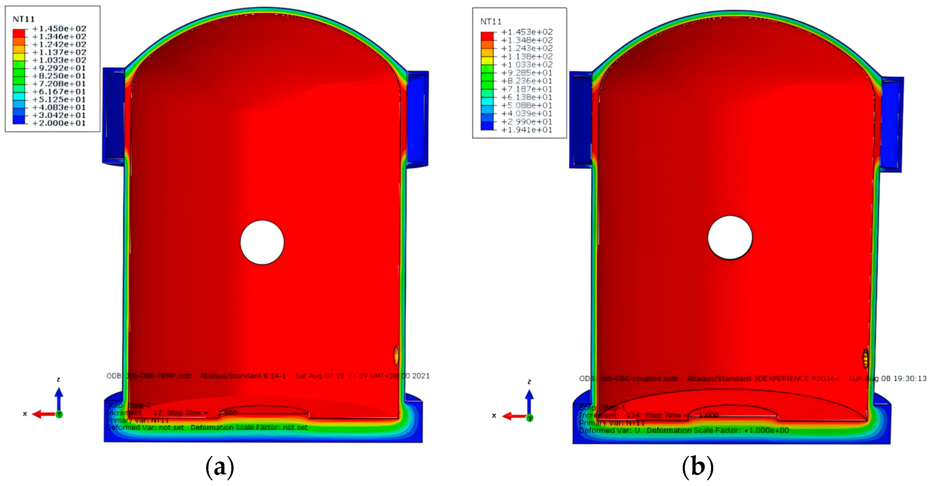
4.1. Structural Integrity Test Conditions

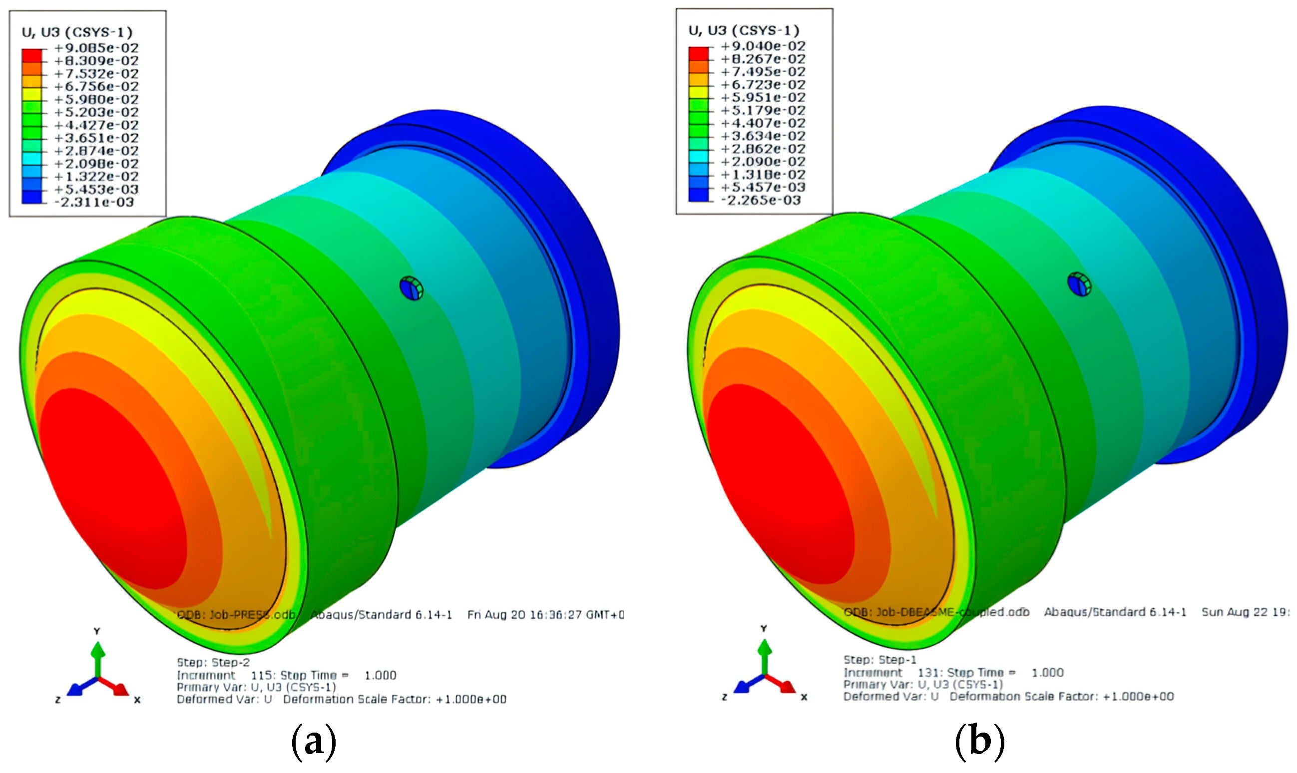
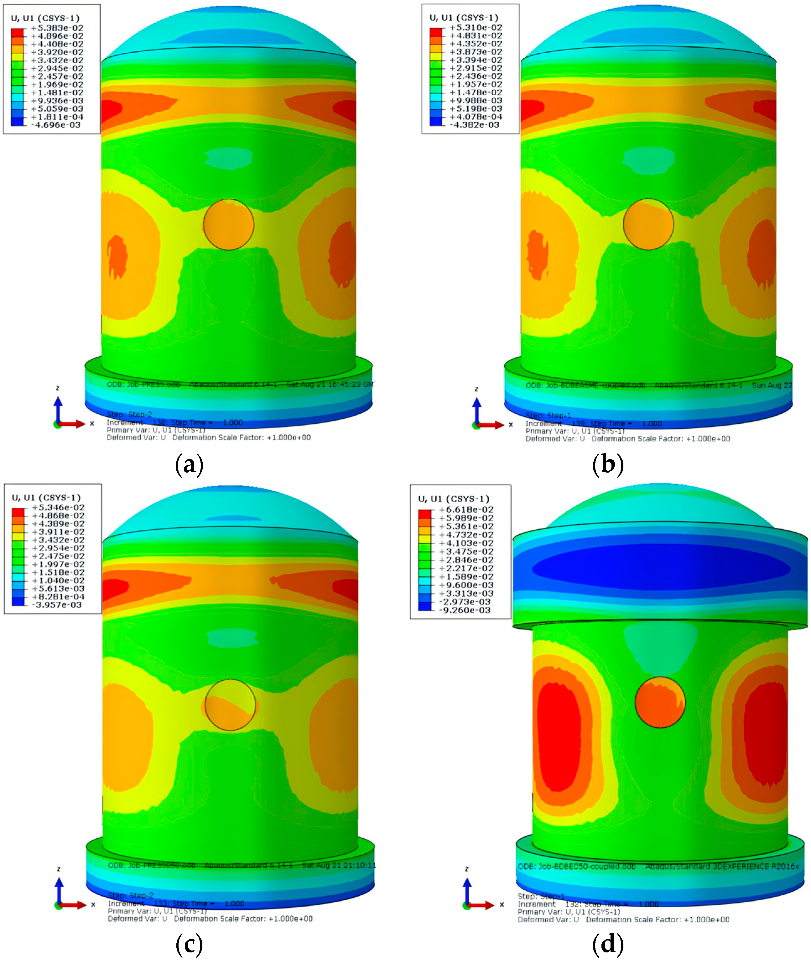
4.1.1. Deformation Analysis

The deformation displacement of the SC containment under pressure conditions of 0.42 MPa and 0.483 Mpa is shown in Figure 12. From Figure 12, it is evident that the maximum deformation area of the SC containment under pressure conditions is located in the 45° area on both sides of the equipment gate opening, which is essentially symmetrically distributed. The maximum radial deformation at 0.42 Mpa is 21.3 mm, and at 0.483 Mpa, it is 24.59 mm. There is a tendency for inward compression on the upper and lower sides of the equipment gate opening, resulting in more complex deformation. This region also experiences significant stress.

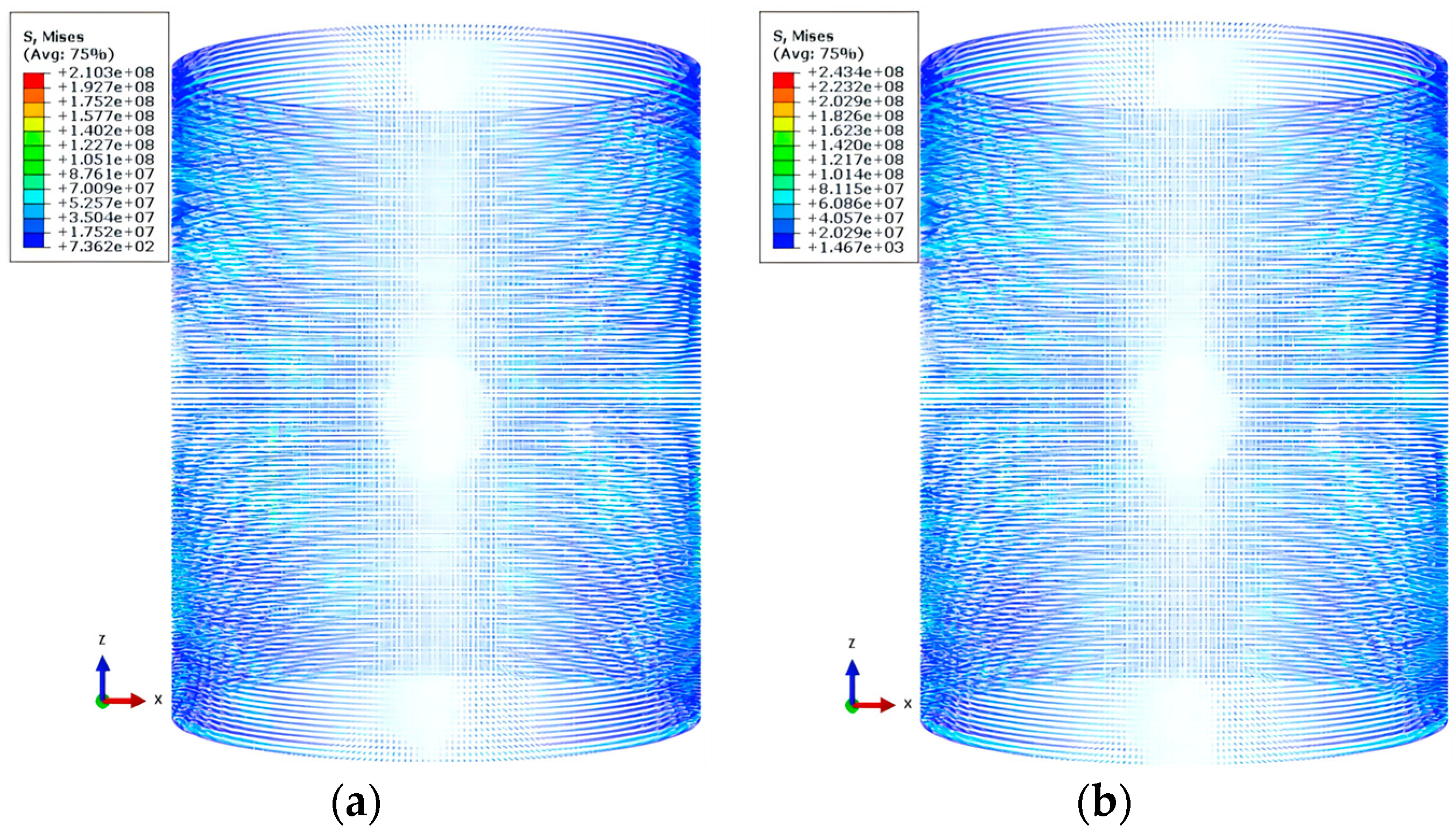
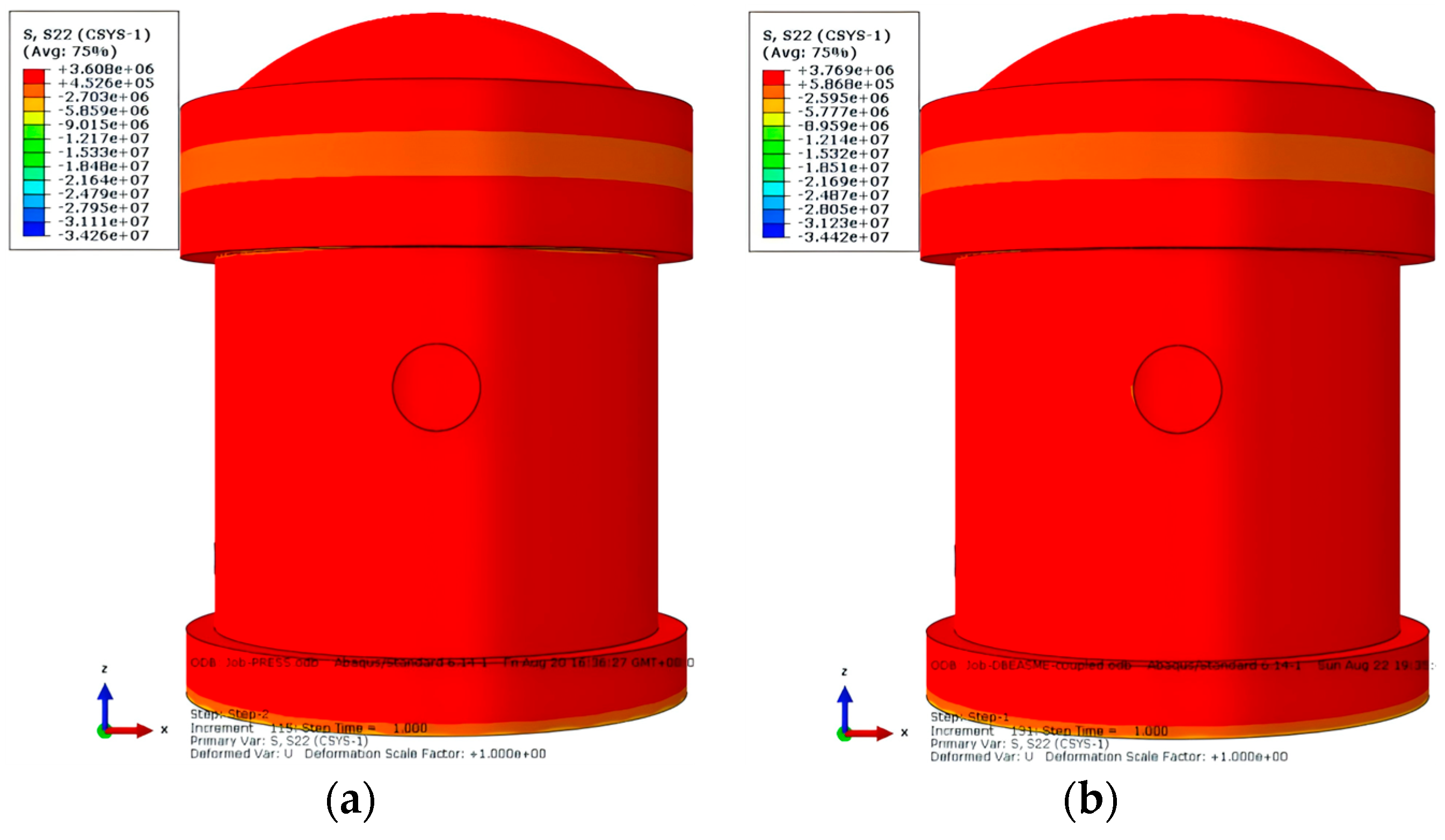
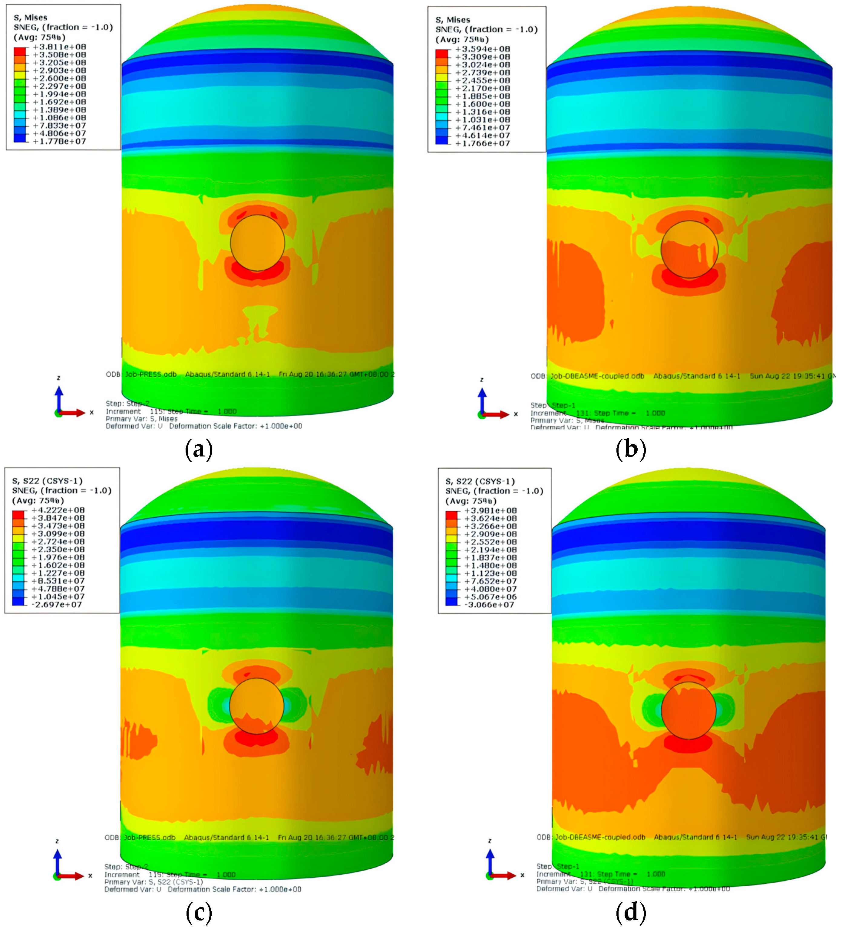
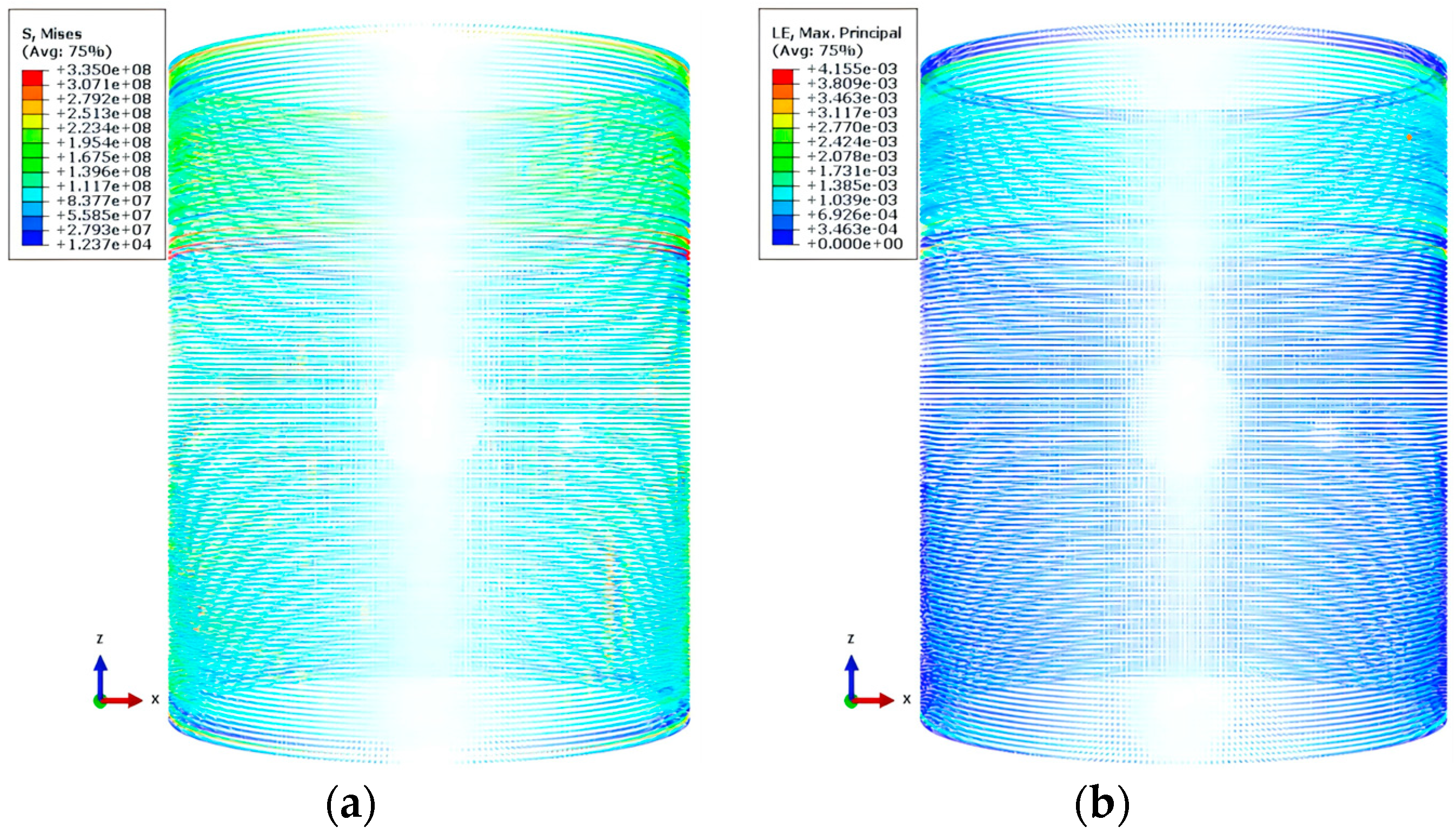
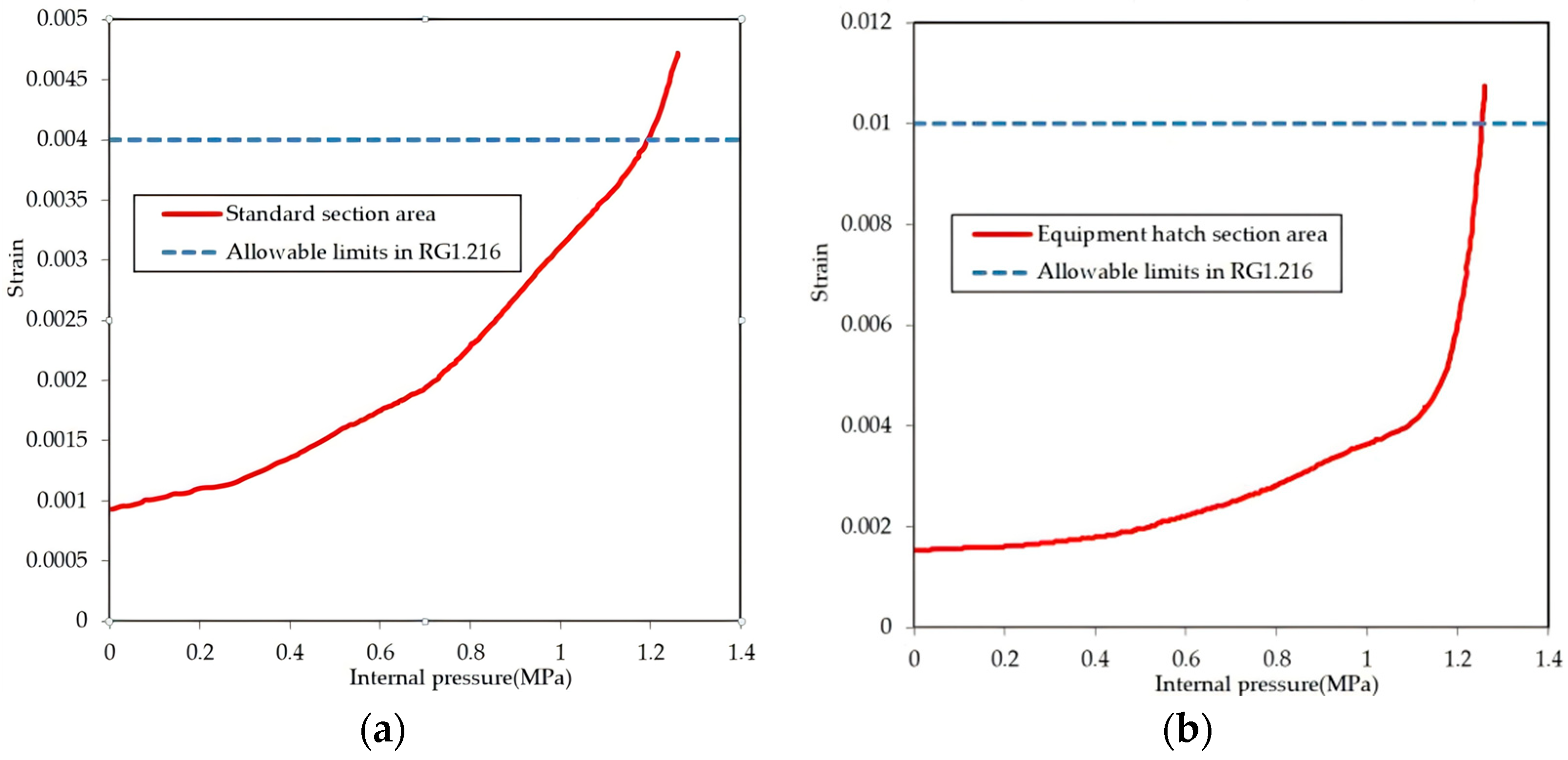
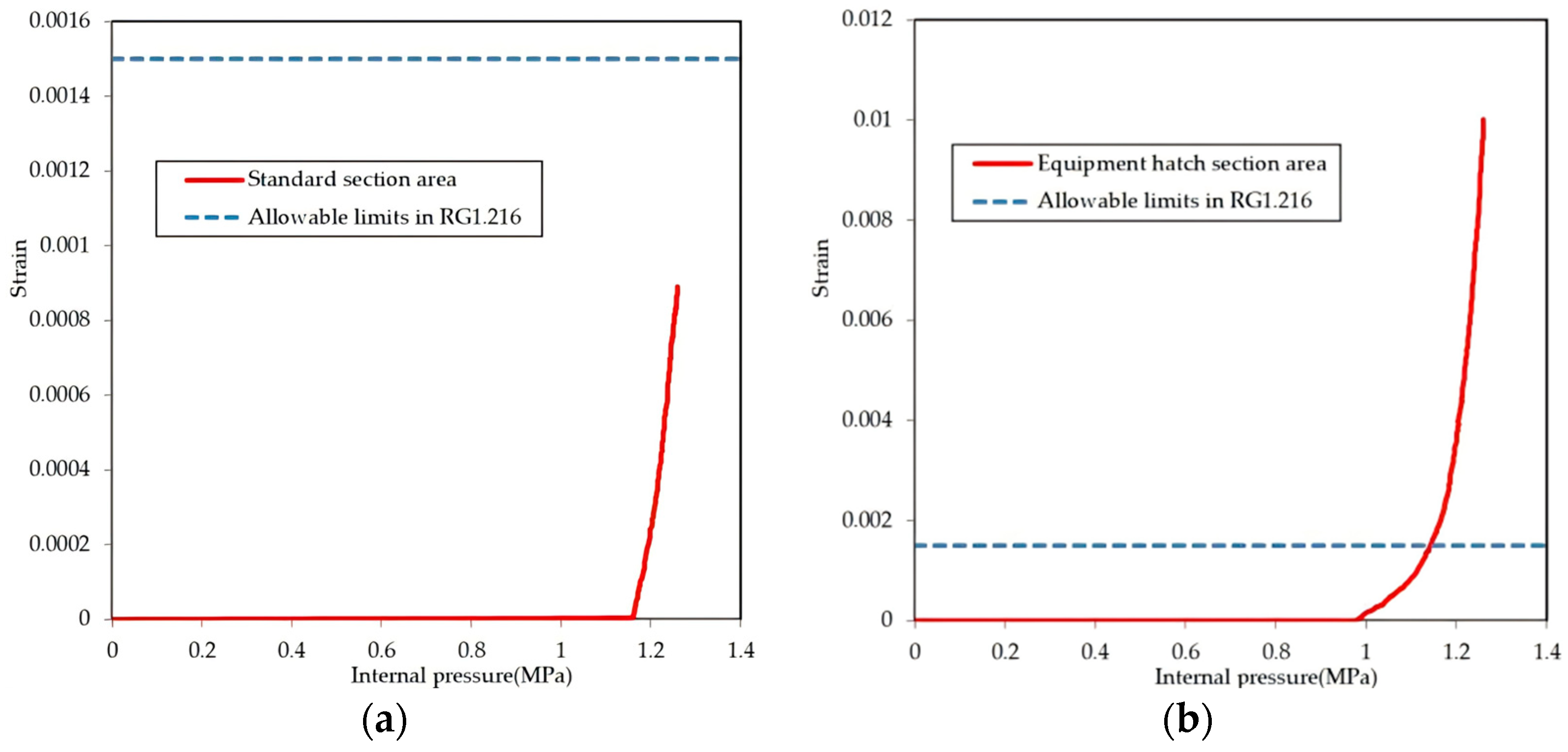
4.1.2. Stress and Strain Analysis

(1) Concrete.
The circumferential stress of the concrete part of the SC containment under pressure conditions of 0.42 Mpa and 0.483 Mpa is shown in Figure 13. It is evident from Figure 13 that under these pressure conditions, the stress distribution of the concrete standard section of the steel plate containment is relatively uniform, without any sudden changes. The circumferential stress at the interface between the raft foundation and the cylinder, as well as the lower part of the water tank, is relatively large. The maximum circumferential stress of the concrete is 2.651 Mpa under 0.42 Mpa pressure and 2.654 Mpa under 0.483 Mpa pressure. The circumferential stress in the cylinder and dome area generally ranges from 0.441 Mpa to 1.704 Mpa, which does not exceed the tensile strength of the concrete.
(2) Internal and outer steel plate.
The Mises stress, circumferential stress, and strain of the inner steel plate of the SC containment under pressure conditions of 0.42 Mpa and 0.483 Mpa are shown in Figure 14. From Figure 14, it is evident that under these pressure conditions, the stress distribution of the standard section of the steel plate on the inner side of the containment is relatively uniform, with no abrupt changes, and the maximum stress and strain occur on the upper and lower sides of the equipment gate opening. The maximum Mises stress of the inner steel plate at 0.42 Mpa is 240.2 Mpa, and at 0.483 Mpa, it is 277.6 Mpa, which does not exceed the yield strength of the steel plate. From Figure 14c,d, it is evident that the circumferential stress in the standard area of the inner steel plate ranges from approximately 122 Mpa to 210.8 Mpa. It is evident from Figure 14e,f that the maximum strain of the inner steel plate under the pressure of 0.42 Mpa is 1.162 × 10⁻³, and under 0.483 Mpa, it is 1.352 × 10⁻³. Both values are less than the limit of 2 × 10⁻³ film strain under the service load of the lining plate, which plays a sealing role in the containment according to ASME Volume III.
The Mises stress, circumferential stress, and strain of the outer steel plate of the sc containment under pressure conditions of 0.42 Mpa and 0.483 Mpa are shown in Figure 15. it is evident from Figure 15 that under these pressure conditions, the stress distribution of the standard section of the outer steel plate of the containment is relatively uniform, with no abrupt changes. the stress and strain in the 45° downward area on both sides of the equipment gate are relatively large. the maximum mises stress of the outer steel plate at 0.42 Mpa is 204.3 Mpa, and at 0.483 Mpa, it is 237.4 Mpa, which is close to the stress of the inner steel plate and does not exceed the yield strength of the steel plate. it is evident from Figure 15c,d that the circumferential stress in the standard area of the outer steel plate ranges from approximately 93.65 Mpa to 192.9 Mpa. it is evident from Figure 15e,f that the maximum strain of the inner steel plate under the pressure of 0.42 Mpa is 9.736 × 10⁻⁴, and under 0.483 Mpa, it is 1.144 × 10⁻³. both values are less than the limit of 2 × 10⁻³ of the membrane strain under the use load of the lining plate, which plays a sealing role in the containment according to ASME Volume iii.
Therefore, from the above calculations and analysis, it is evident that the sealing of the sc containment can be ensured by the inner and outer steel plates under the given pressure conditions. the integrity of the containment can be ensured by the combined strength of the inner and outer steel plates and the concrete.
(3) Anchors and tendons.
The Mises stress of the anchors and tendons under pressure conditions of 0.42 Mpa and 0.483 Mpa are shown in Figure 16. The maximum Mises stress values of the anchors and tendons at 0.42 Mpa and 0.48 Mpa were 210.3 Mpa and 243.4 Mpa, respectively, which did not exceed their yield stress of 335 Mpa.

4.2. Design Basis Conditions

4.2.1. Deformation Analysis

The temperature distribution, radial displacement, and vertical displacement of the SC containment under the design basis condition (design basis pressure 0.42 Mpa, containment temperature 145 °C) are shown in Figure 17, Figure 18 and Figure 19. Since the atmospheric temperature of the containment under accident conditions is 145 °C, convective heat transfer and thermal radiation occur between the atmosphere of the containment and the steel liner. In this study, a temperature of 145 °C is directly applied to the inner steel plate. It is evident from Figure 17 that the temperature is distributed in a gradient along the thickness of the containment wall, and the temperature distribution obtained by the sequential coupling method is consistent with that of the fully coupled method, demonstrating the reliability of both methods. From Figure 18 and Figure 19, it is evident that the maximum radial displacement of the SC containment under the design basis condition appears in the water tank area, which also has a high temperature, and the maximum vertical displacement appears in the dome area. The displacement distribution obtained by the sequential coupling method is essentially the same as that obtained by the full coupling method. The maximum radial displacement and vertical displacement values obtained by the sequential coupling method are 47.61 mm and 90.85 mm, respectively. The maximum radial displacement and vertical displacement values obtained by the full coupling method are 46.76 mm and 90.40 mm, respectively. The results obtained by the sequential coupling method are slightly larger than those obtained by the full coupling method. This difference arises because the sequential coupling method is a linear superposition of temperature deformation and mechanical deformation, whereas the full coupling method considers the interaction between the two, resulting in slightly smaller values. The radial displacement value of the SC containment, considering the 145 °C, is twice as large as that without the temperature consideration. This finding is consistent with the OECD-NEA’s containment benchmark research conclusion that the deformation of the containment structure increases significantly after considering the temperature load, especially after accounting for material performance degradation.

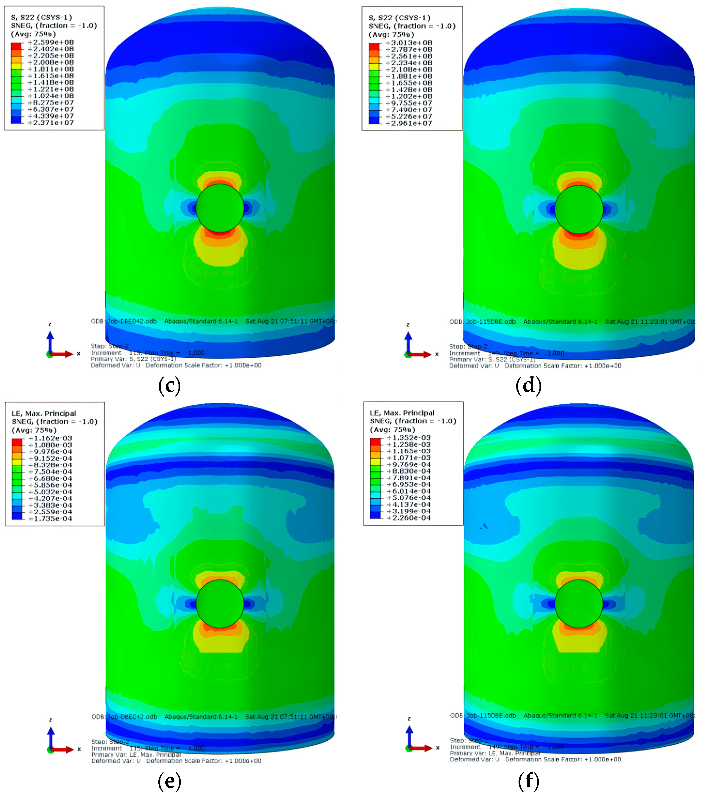
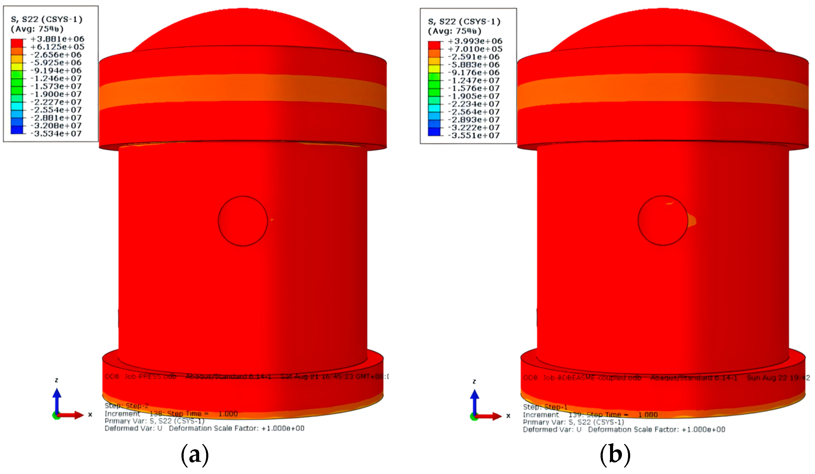
4.2.2. Stress and Strain Analysis

(1) Concrete.
The circumferential stress of the concrete part of the SC containment under the design basis condition is shown in Figure 20. It is evident from Figure 20 that under the design basis condition, the stress distribution of the concrete standard section of the steel plate containment is relatively uniform, with no abrupt changes. The tensile damage of the concrete occurs due to the combined action of membrane stress and bending stress under the design basis condition. At this time, the sealing and integrity of the SC containment are ensured by the inner and outer steel plates.
(2) Internal and outer steel plate.
The Mises stress, circumferential stress, and strain of the inner steel plate of the SC containment under the design basis condition are shown in Figure 21. It is evident from Figure 21 that under the design basis condition, the stress distribution of the standard section of the steel plate inside the steel containment is relatively uniform, with no abrupt changes. The stress and strain on the upper and lower sides of the equipment gate opening are higher. The maximum Mises stress of the inner steel plate under the sequential coupling method and the full coupling method is 270.7 Mpa and 257.3 Mpa, respectively, which does not exceed the yield strength of the steel plate. From Figure 21c,d, it is evident that the circumferential stress in the standard area of the inner steel plate is under pressure in some areas due to the combined action of bending stress and internal pressure. At this time, the internal contraction effect of the bending stress on the inner steel plate is greater than the external expansion effect caused by internal pressure. It is evident from Figure 21e,f that the maximum strain of the inner steel plate under the design basis condition is 2.293 × 10⁻³ and 2.271 × 10⁻³, respectively, under the sequential coupling method and the full coupling method, which is less than the limit of 4 × 10⁻³ for the combined film and bending strain under the use load of the lining plate with a sealing effect, as specified in ASME Volume III.
The Mises stress, circumferential stress, strain, and equivalent plastic strain of the outer steel plate of the SC containment under the design basis condition are shown in Figure 22. It is evident from Figure 22 that the stress and strain of the outer steel plate are greater than those of the inner steel plate. Under the design basis condition, the Mises stress of the outer steel plate of the SC containment, under the combined action of bending stress and membrane stress, does not reach its yield strength. The maximum circumferential stress values of the outer steel plate under the sequential coupling method and the full coupling method are 422.2 Mpa and 398.1 Mpa, respectively, appearing in the upper and lower areas of the equipment gate opening. The circumferential stress in the standard area ranges between 309.9 Mpa and 384.7 Mpa, which does not reach its yield strength. It is evident from Figure 22e,f that the maximum strain values of the outer steel plate under the design basis conditions under the sequential coupling method and the full coupled method are 2.467 × 10⁻³ and 2.310 × 10⁻³, respectively, which are less than the limit of 4 × 10⁻³ for the combined film and bending strain under the use load of the lining plate with a sealing effect, as specified in ASME Volume III. From Figure 22g,h, it is evident that the outer steel plate has not yet exhibited plastic strain under these working conditions.
Therefore, it is evident from the above calculations and analysis that the stress and strain of the outer steel plate of the SC containment are significantly greater than those of the inner steel plate under the design basis condition, and the sealing and integrity of the containment are mainly ensured by the inner and outer steel plates.

4.3. Severe Accident Conditions

4.3.1. Deformation Analysis

The radial displacement of the SC containment under two severe accident conditions (temperature of 150 °C, pressure of 0.55 Mpa, and temperature of 154 °C, pressure of 0.5 Mpa) is shown in Figure 23. From Figure 23, it is evident that the maximum radial displacement of the SC containment under severe accident conditions appears in the water tank area, which is consistent with the displacement distribution area of the design basis condition. The displacement obtained by the sequential coupling method and the full coupling method is essentially the same. The radial deformation value of the containment at 150 °C and 0.55 Mpa is 53.83 mm, which is greater than the deformation value of 53.46 mm at 154 °C and 0.50 Mpa. Therefore, the following analysis mainly focuses on the calculation results for a temperature of 150 °C and pressure of 0.55 Mpa.

4.3.2. Stress and Strain Analysis

(1) Concrete.
The circumferential stress of the concrete part of the SC containment under severe accident conditions is shown in Figure 24. It is evident from the diagram that under severe accident conditions, the stress distribution of the standard section of steel containment concrete is relatively uniform, with no abrupt changes. Tensile damage occurs in the concrete due to the combined action of membrane stress and bending stress under severe accident conditions. At this time, the sealing and integrity of the SC containment are ensured by the inner and outer steel plates.
(2) Internal and outer steel plate.
The Mises stress, circumferential stress, and strain of the inner steel plate of the SC containment under severe accident conditions are shown in Figure 25. It is evident from Figure 25 that under severe accident conditions, the stress distribution of the standard section of the steel plate inside the steel containment is relatively uniform, with no abrupt changes. The stress and strain on the upper and lower sides of the equipment gate opening are higher, which is consistent with the stress and strain distribution under the design basis condition. The maximum circumferential stress of the inner steel plate under the sequential coupling method and the complete coupling method is 143.7 Mpa and 118.7 Mpa, respectively, which does not exceed the yield strength of the steel plate. The maximum strain of the inner steel plate under severe accident conditions is 2.631 × 10⁻³ and 2.622 × 10⁻³, respectively, under the sequential coupling method and the complete coupling method, which is less than the limit of 4 × 10⁻³ for the combined film and bending strain under the use load of the lining plate with a sealing effect, as specified in ASME Volume III, and less than the limit of 1 × 10⁻² for the combined film and bending strain under the ultimate design load.
The Mises stress, circumferential stress, strain, and equivalent plastic strain of the outer steel plate of the SC containment under severe accident conditions are shown in Figure 26. It is evident from Figure 26 that the stress and strain of the outer steel plate are greater than those of the inner steel plate. Under severe accident conditions, the maximum Mises stress and circumferential stress of the outer steel plate of the SC containment shell under the sequential coupling method and the complete coupling method appear on the upper and lower sides of the equipment gate opening. The maximum values are 464.3 Mpa and 451.2 Mpa, respectively, which exceed their yield strength but do not reach their tensile strength. The maximum strain values of the outer steel plate under the sequential coupling method and the complete coupling method are 2.815 × 10⁻³ and 2.601 × 10⁻³, respectively, which are less than the limit of 1 × 10⁻² for the combined film and bending strain under the ultimate design load of the lining plate with a sealing effect, as specified in ASME Volume III. It is evident from Figure 26g,h that under the sequential coupling method, the plastic deformation of the outer steel plate begins to appear near the gate opening of the equipment, and the equivalent plastic deformation value is about 3.273 × 10⁻⁴.
Therefore, it is evident from the above calculations and analysis that under severe accident conditions, the stress and strain of the outer steel plate of the containment are significantly greater than those of the inner steel plate, and the sealing and integrity of the containment are mainly ensured by the inner and outer steel plates.
(3) Anchors and tendons.
The Mises stress and strain of anchors and tendons under severe accident conditions are shown in Figure 27. It is evident from the diagram that the Mises stress of anchors and tendons in some areas reaches their yield strength of 335 Mpa, which is mainly concentrated near the interface between the ASP tank and the cylinder, where the force is also more complex. The maximum strain value is 4.155 × 10⁻³, which is less than the limit of 1 × 10⁻² for the combined film and bending strain under the ultimate design load specified in ASME Volume III.

4.4. Failure Criterion and Ultimate Bearing Capacity

4.4.1. Failure Criterion

The containment is the last barrier for nuclear power plants to prevent the release of nuclear fission products to the environment under accident conditions. The realization of this function depends on the sealing effect formed by the integrity of the steel plate in the containment. Therefore, the ultimate bearing capacity of the containment structure will depend on whether the containment can continue to withstand internal pressure and ensure the integrity of the steel plate.
In this paper, one of the four conditions is used as the criterion for the loss of integrity of the containment:
(1) The regional yield of the inner steel plate occurs, and the yield area reaches more than 10 m2. This acceptance criterion is based on the engineering practice of some nuclear power plants.
(2) According to the research results of OECD-NEA on the international standard of containment integrity (ISP48) [33]: When the maximum equivalent plastic strain of the containment steel lining exceeds 0.30% ± 0.15%, the steel lining is likely to be regionally torn. Therefore, when the maximum equivalent plastic strain of the inner steel plate reaches 0.15%, the containment structure reaches the ultimate bearing capacity.
(3) According to the provisions of ASME III CC-3710 [47]: When the steel lining is under the ultimate design load, the combined film and bending strain of the steel lining should not be more than 1%. In this paper, the maximum strain value of the inner steel plate reaches 1% as the containment reaches the ultimate bearing capacity.
(4) According to the provisions of RG1.216 [48]: Except for the prestressed steel bundle material, the overall strain of other materials in the discontinuous region should not exceed 0.4%. Therefore, in this paper, the maximum strain value of the discontinuous region reaches 0.4% as the containment reaches the ultimate bearing capacity.

4.4.2. Ultimate Bearing Capacity

Due to the conservative nature of the sequential coupling method’s calculation results compared to the full coupling method, this paper primarily presents the calculation results of the sequential coupling method. This paper utilizes OECD-NEA guidelines to analyze and examine the time history curves of pressure and temperature in the containment following a severe accident, as depicted in Figure 28, to evaluate the ultimate bearing capacity of the SC containment. Representative observation points near the standard section area and the equipment hatch section area are selected to observe the strain-pressure curve and the equivalent plastic strain-pressure curve, as shown in Figure 29 and Figure 30. The diagram indicates that the SC containment undergoes elastic, local plastic, elastic-plastic, and large deformation states during heating and pressurization. According to the failure criterion, when the strain value of the standard area reaches approximately 0.4%, the internal pressure is about 1.19 Mpa. When the maximum equivalent plastic strain of the inner steel plate reaches 0.15%, the internal pressure is about 1.14 Mpa. When the maximum strain value of the inner steel plate reaches 1%, the internal pressure is about 1.25 Mpa. When the yield area of the inner steel plate reaches 10 m2, the internal pressure is about 0.91 Mpa, as shown in Figure 31. Therefore, it can be concluded that when the internal pressure reaches 0.91 Mpa, the containment reaches its ultimate bearing capacity.

5. Conclusions and Recommendations

This study demonstrates that steel-plate concrete containment structures offer significant advantages in strength and safety margins for third-generation nuclear power plants. The findings support their use as a viable alternative to traditional designs, with the potential for further optimization and broader application in diverse reactor systems:
1. The steel-plate concrete containment structure is recommended to adopt a single-layer containment design, with the inner steel plate continuously covering the entire containment dome, cylinder wall, bottom plate, and the inner surface of the ASP tank. This steel plate serves as a pressure boundary to prevent leakage, while the outer steel plate protects against external impacts. The internal and outer steel plates can also serve as construction templates. The recommended thicknesses are 30 mm for the outer steel plate and 25 mm for the inner steel plate, with a concrete thickness of 1.1 m. Both steel plates should be made of SA-738 Gr. B steel, as used in the AP1000 containment. The anchorage system, consisting of intersecting grids, should be embedded within the concrete structure and welded to the steel plate, ensuring stability and resistance to out-of-plane shear forces.
2. The steel-plate concrete containment has a high safety margin under pressure conditions, with stress and strain levels well within safe limits. The maximum deformation occurs symmetrically on both sides of the equipment gate opening, confirming the containment’s robustness.
3. Under design basis conditions, the containment maintains a high safety margin, with stress and strain levels far below critical thresholds. The maximum radial and vertical displacements occur in high-temperature areas, such as the water tank and dome, but remain within acceptable limits. The findings align with previous studies, highlighting the increased deformation under temperature effects.
4. Under severe accident conditions, the containment exhibits significant resilience, with stress and strain levels in the steel plates remaining below yield strengths. The sequential coupling method’s conservative calculations confirm the containment’s integrity, even under extreme conditions.
5. The ultimate bearing capacity of the containment is reached when the internal pressure exceeds 0.91 MPa, which is 2.17 times the design pressure. This threshold marks the containment’s ability to withstand extreme internal pressures, ensuring its role as a final safety barrier.

Author Contributions

Conceptualization, G.R. and R.P.; methodology, G.R. and R.P.; software, G.R., Z.D. and T.L.; validation, F.S.; formal analysis, G.R. and R.P.; investigation, G.R. and F.S.; resources, G.R.; data curation, G.R.; writing—original draft preparation, G.R.; writing—review and editing, R.P., F.S. and Z.D.; visualization, G.R. and T.L.; project administration, R.P. and F.S.; funding acquisition, G.R. All authors have read and agreed to the published version of the manuscript.

Funding

This research received no external funding.

Data Availability Statement

The original contributions presented in this study are included in the article; further inquiries can be directed to the corresponding author.

Conflicts of Interest

Authors Zhanfa Dong and Tianyun Lan were employed by the company China Nuclear Power Design Co., Ltd. (Shenzhen). The remaining authors declare that the research was conducted in the absence of any commercial or financial relationships that could be construed as a potential conflict of interest.

References

  1. Frano, R.L.; Forasassi, G. Dynamic Response of a Nuclear Power Plant Subjected to External Accident Event. In Proceedings of the 18th International Conference on Nuclear Engineering, Xi’an, China, 17–21 May 2010; pp. 607–615. [Google Scholar]
  2. Ryzhov, S.B.; Mokhov, V.A.; Nikitenko, M.P.; Bessalov, G.G.; Podshibyakin, A.K.; Anufriev, D.A.; Gadó, J.a.; Rohde, U. VVER-Type Reactors of Russian Design. In Handbook of Nuclear Engineering; Cacuci, D.G., Ed.; Springer: Boston, MA, USA, 2010; pp. 2249–2320. [Google Scholar] [CrossRef]
  3. Sener, K.C.; Varma, A.H.; Wang, S.; Bhardwaj, S.R.; Gallocher, S. Modular steel-plate composite (SC) wall steelbricks: Experimental and numerical evaluations. Nucl. Eng. Des. 2019, 350, 224–233. [Google Scholar] [CrossRef]
  4. Zhu, X.; Li, J.; Lin, G.; Pan, R.; Li, L. Sensitivity Analysis of Steel-Plate Concrete Containment against a Large Commercial Aircraft. Energies 2021, 14, 2829. [Google Scholar] [CrossRef]
  5. Pan, R.; Wu, J.; Zhang, X. Application and development of steel plate reinforced concrete structure in nuclear power engineering. Ind. Constr. 2014, 44, 1–6. [Google Scholar]
  6. Ning, J.; Bao, F.; Fang, J. Experimental research on seismic behavior of low shear-span ratio composite shear wall with double steel plates and infill concrete. J. Build. Struct. 2011, 32, 74–81. [Google Scholar] [CrossRef]
  7. Chen, J.; Jun, Z. Construction Technology of Composite Structure of Double Steel Plate and Shear Wall in Yancheng Broadcast Television Tower. Constr. Technol. 2011, 40, 17–20. [Google Scholar]
  8. Tokyo Electric Power Company (TEPCO). Improved Construction and Project Management; TEPCO: Tokyo, Japan, 2001. [Google Scholar]
  9. JEAG 4618-2005; Technical Guidelines for Aseismic Design of Steel Plate Reinforced Concrete Structures: Buildings and Structures. Japan Electric Association: Tokyo, Japan, 2005.
  10. JEAG 4618-2009; Technical Code for Seismic Design of Steel Plate Reinforced Concrete Structures: Buildings and Structures. Japan Electric Association Nuclear Safety: Tokyo, Japan, 2009.
  11. Korea Electric Power Industry Code-Structural Nuclear Grade. Specification for Safety-Related Steel Plate Concrete Structures for Nuclear Facilities. Board of KEPIC Policy, Structural Committee; Korea Electric Association: Seoul, Republic of Korea, 2010. [Google Scholar]
  12. ANSI/AISC N690s1-15; Specification for Safety-Related Steel Structures for Nuclear Facilities. American Institute of Steel Construction: Chicago, IL, USA, 2015; pp. 1–15.
  13. Ministry of Housing and Urban Development–Regulation Construction. GB/T 51340-2018; Technical Standard for Steel Plate Concrete Structures of Nuclear Power Plants. China Planning Press: Beijing, China, 2018.
  14. Zhang, J.-L.; Liu, B.-D.; Zhang, P.-Y.; Wang, Z.-H. Small-scale test and analysis of corrugated-steel-plate–concrete composite member adopting novel shear connectors. Eng. Struct. 2019, 184, 369–383. [Google Scholar] [CrossRef]
  15. Wang, Q. The Structural Design and Shock-Resistant Performance of Steel Beam-Concrete Column Frame Structure; Springer: Cham, Switzerland, 2020; pp. 1020–1026. [Google Scholar]
  16. Zhou, T.; Wang, J.; Sawab, J.; Chen, H.; Mo, Y.L. Biaxial steel plated concrete constitutive models for composite structures: Implementation and validation. J. Constr. Steel Res. 2021, 177, 106452. [Google Scholar] [CrossRef]
  17. Wu, L.; Wang, H.; Lin, Z. Ultimate strength behavior of steel plate-concrete composite slabs: An experimental and theoretical study. Steel Compos. Struct. 2020, 37, 741–759. [Google Scholar] [CrossRef]
  18. Liu, R.; Yang, Y. Research on fatigue performance of steel-plate-concrete composite slab. Thin-Walled Struct. 2021, 160, 107339. [Google Scholar] [CrossRef]
  19. Szewczyk, P.; Szumigała, M. Optimal Design of Steel–Concrete Composite Beams Strengthened Under Load. Materials 2021, 14, 4715. [Google Scholar] [CrossRef]
  20. Ma, Z.; Wu, Y.; Zhang, J.; Zhang, M. Experimental Study on Seismic Behavior of Coupled Steel Plate and Reinforced Concrete Composite Wall. Buildings 2022, 12, 2036. [Google Scholar] [CrossRef]
  21. Liu, A.; Wu, Y.; Wang, B.; Chen, X. Seismic Design and Performance Evaluation of Coupled Steel Plate and Reinforced Concrete Composite Walls. Buildings 2023, 13, 2242. [Google Scholar] [CrossRef]
  22. Wang, B.; Chen, P.; Jiang, H.; Wang, J. Performance of steel-plate-reinforced concrete composite walls in tall structures. Proc. Inst. Civ. Eng.—Civ. Eng. 2024, 177, 118–125. [Google Scholar] [CrossRef]
  23. Appa Rao, T.V.S.R. Behavior of Concrete Nuclear Containment Structures up to Ultimate Failure with Special Reference to MAPP-1 Containment, Inelastic Behavior; Structural Engineering Research Centre: Madras, India, 1975. [Google Scholar]
  24. Donten, K.; Knauff, M.; Sadowski, A.; Scibak, W. Tests on Model of Prestressed Reactor Containment; Institute of Nuclear Research: Otwock, Poland, 1980; pp. 231–245. [Google Scholar]
  25. NUREG/CR-5825; Post-Test Report on Testing and Analysis of the Sizewell-B 1:10-Scale Containment Model. ANATECH Research Corp.: San Diego, CA, USA, 1991.
  26. NUREG/CR-6810; Overpressurization Test of a 1:4-Scale Prestressed Concrete Containment Vessel Model. Sandia National Laboratories: Albuquerque NM, USA, 2003.
  27. Zhao, X.; Yao, D.; Gao, J.; Tan, J.; Hao, X. A simulation research on thermal-pressure coupling loading of a 1:3.2 containment model. J. Nucl. Sci. Technol. 2024, 150, 1–14. [Google Scholar] [CrossRef]
  28. Zhao, C.; Li, Z.L.; Dong, Z. Ultimate bearing capacity analysis on containment structure of CPR1000. Comput. Aided Eng. 2013, 22, 393–398. [Google Scholar]
  29. Song, C.; Hou, G.; Zhou, G. Ultimate Capacity and Influenced Factors Analysis of Nuclear RC Containment Subjected to Internal Pressure. Chin. J. Nucl. Sci. Eng. 2014, 34, 228–235. [Google Scholar]
  30. Ren, G.; Pan, R.; Sun, F. Imulation of behaviors of a one-third scale containment model test. In Proceedings of the 25th International Conference on Nuclear Engineering, Shanghai, China, 15–19 April 2017. [Google Scholar]
  31. Chakraborty, M.K.; Acharya, S.; Pisharady, A.S.; Roshan, A.D.; Bishnoi, L.R. Assessment of Ultimate Load Capacity of concrete containment structures against structural collapse. Nucl. Eng. Des. 2017, 323, 417–426. [Google Scholar] [CrossRef]
  32. Tong, L.; Zhou, X.; Cao, X. Ultimate pressure bearing capacity analysis for the prestressed concrete containment. Ann. Nucl. Energy 2018, 121, 582–593. [Google Scholar] [CrossRef]
  33. Nuclear Energy Agency/Committee on the Safety of Nuclear Installations. International Standard Problem No. 48 Containment Capacity; Nuclear Energy Agency/Committee on the Safety of Nuclear Installations: Paris, France, 2005. [Google Scholar]
  34. Huang, X.; Kwon, O.-S.; Bentz, E.; Tcherner, J. Evaluation of CANDU NPP containment structure subjected to aging and internal pressure increase. Nucl. Eng. Des. 2017, 314, 82–92. [Google Scholar] [CrossRef]
  35. Mahida, P.A.; Desai, D. Structural response evaluation of reinforced-concrete nuclear containment structure subjected to internal overpressure with high-temperature loading. Int. J. Nucl. Energy Sci. Technol. 2020, 14, 281–290. [Google Scholar] [CrossRef]
  36. Yuqin, G. The Study on the Ultimate Bearing Capability of Nuclear Power Plant’s Containment with Temperature Effect; Harbin Engineering University: Harbin, China, 2015. [Google Scholar]
  37. Lin, S.; Hu, Z.; Han, J. Experimental Studies on Friction Loss of Prestress of Containment Vessel in an EPR Nuclear Power Plant. Spec. Struct. 2022, 39, 57–60. [Google Scholar]
  38. Asmolov, V.G.; Gusev, I.N.; Kazanskiy, V.R.; Povarov, V.P.; Statsura, D.B. New generation first-of-the kind unit—VVER-1200 design features. Nucl. Energy Technol. 2017, 3, 260–269. [Google Scholar] [CrossRef]
  39. Liu, J.; Han, P. Numerical Analyses of a Shield Building Subjected to a Large Commercial Aircraft Impact. Shock. Vib. 2018, 2018, 7854969. [Google Scholar] [CrossRef]
  40. GE-Hitachi Nuclear Energy Americas, LLC. BWRX-300 Steel-Plate Composite Containment Vessel (SCCV) and Reactor Building (RB) Structural Design–Non-Proprietary Information; GE-Hitachi Nuclear Energy Americas, LLC: Wilmington, NC, USA, 2023. [Google Scholar]
  41. GB-50010-2010; Specification for Design of Concrete Structures. China Construction Industry Press: Beijing, China, 2011.
  42. EN1994-1-2; Eurocode 4-Design of Composite Steel and Concrete Structures-Part 1-2: General Rules—Structural Fire Design. British Standards Institution: London, UK, 2005.
  43. The American Society of Mechanical Engineers. ASME Boiler & Pressure Vessel Code II Part A; The American Society of Mechanical Engineers: New York, NY, USA, 2007. [Google Scholar]
  44. GB 51249-2017; Code for Fire Safety of Steel Structures in Buildings. China Planing Press: Beijing, China, 2017.
  45. Jin, S.; Li, Z.; Lan, T.; Dong, Z.; Gong, J. Nonlinear Finite Element Analysis of Prestressed Concrete Containment Vessel under Severe Accident Loads. KSCE J. Civ. Eng. 2020, 24, 816–825. [Google Scholar] [CrossRef]
  46. Federal Association of Fire Protection Engineers Design. Rules for Design and Construction of PWR Nuclear Civil Works: RCC-CW. Paris; French Association for Design: Paris, France, 2015; pp. 7–8. [Google Scholar]
  47. American Society of Mechanical Engineers. ASME Boiler & Pressure Vessel Code III Division 2-Code for Concrete Containments:ACI 359; The American Society of Mechanical Engineers: New York, NY, USA, 2004. [Google Scholar]
  48. Nuclear Regulatory Commission. Rule 1.206, Revision. Containment Structural Integrity Evaluation for Internal Pressure Loadings above Design Basis Pressure; Nuclear Regulatory Commission: Rockville, MD, USA, 2010. [Google Scholar]
Figure 1. Research process for evaluating SC containment structures.
Buildings 14 02771 g001
Figure 2. (a) The cross-sectional structure of the inner containment of the CPR1000 reactor; (b) the cross-sectional structure of the inner containment of the HPR1000 reactor.
Buildings 14 02771 g002
Figure 3. (a) The cross-sectional structure of the inner containment of the EPR reactor; (b) schematic of the VVER reactor containment structure.
Buildings 14 02771 g003
Figure 4. (a) The cross-sectional structure of the inner containment of the CAP1400 reactor; (b) section view of the integrated reactor building of the BWRX-300.
Buildings 14 02771 g004
Figure 5. The cross-sectional structure of the containment.
Buildings 14 02771 g005
Figure 6. (a) The FE model of the concrete; (b) The FE model of the steel plate; (c) the FE model of the equipment penetration; (d) the FE model of the ASP tank.
Buildings 14 02771 g006
Figure 7. (a) The photograph of the containment mock-up; (b) the general view of the containment.
Buildings 14 02771 g007
Figure 8. (a) The containment model; (b) the arrangement of prestressing tendons.
Buildings 14 02771 g008
Figure 9. The locations of sensors on the containment mock-up.
Buildings 14 02771 g009
Figure 10. (a) The actual cracking observed in the dome area during the pressurization test; (b) the cracking pattern at the bottom of the perimeter wall near the base slab.
Buildings 14 02771 g010
Figure 11. The predicted cracking pattern from numerical analysis.
Buildings 14 02771 g011
Figure 12. (a) The overall deformation under a pressure of 0.42 Mpa; (b) the overall deformation under a pressure of 0.483 Mpa.
Buildings 14 02771 g012
Figure 13. (a) The circumferential stress of the concrete under a pressure of 0.42 Mpa; (b) the circumferential stress of the concrete under a pressure of 0.483 Mpa.
Buildings 14 02771 g013
Figure 14. (a) The Mises stress of the inner steel plate under a pressure of 0.42 Mpa; (b) the Mises stress of the inner steel plate under a pressure of 0.483 Mpa; (c) the circumferential stress of the inner steel plate under a pressure of 0.42 Mpa; (d) the circumferential stress of the inner steel plate under a pressure of 0.483 Mpa; (e) the circumferential strain of the inner steel plate under a pressure of 0.42 Mpa; (f) the circumferential strain of the inner steel plate under a pressure of 0.483 Mpa.
Buildings 14 02771 g014aBuildings 14 02771 g014b
Figure 15. (a) The mises stress of the outer steel plate under a pressure of 0.42 Mpa; (b) the Mises stress of the outer steel plate under a pressure of 0.483 Mpa; (c) the circumferential stress of the outer steel plate under a pressure of 0.42 Mpa; (d) the circumferential stress of the outer steel plate under a pressure of 0.483 Mpa; (e) the circumferential strain of the outer steel plate under a pressure of 0.42 Mpa; (f) the circumferential strain of the outer steel plate under a pressure of 0.483 Mpa.
Buildings 14 02771 g015
Figure 16. (a) The Mises stress of the anchors and tendons under a pressure of 0.42 Mpa; (b) the Mises stress of the anchors and tendons under a pressure of 0.483 Mpa.
Buildings 14 02771 g016
Figure 17. (a) The temperature distribution map of the SC containment under the design basis condition is obtained using the sequential coupling method; (b) the temperature distribution map of the SC containment under the design basis condition is obtained using the full coupling method.
Buildings 14 02771 g017
Figure 18. (a) The radial displacement of the SC containment under design basis conditions based on the sequential coupling method; (b) the radial displacement of the SC containment under design basis conditions based on the full coupling method.
Buildings 14 02771 g018
Figure 19. (a) The vertical displacement of the SC containment under the design basis condition is calculated using the sequential coupling method; (b) the vertical displacement of the SC containment under the design basis condition is calculated using the full coupling method.
Buildings 14 02771 g019
Figure 20. (a) The circumferential stress of the SC containment under design basis conditions based on the sequential coupling method; (b) the circumferential stress of the SC containment under design basis conditions based on the full coupling method.
Buildings 14 02771 g020
Figure 21. (a) The Mises stress of the inner steel plate under the design basis condition based on the sequential coupling method; (b) the Mises stress of the inner steel plate under the design basis condition based on the full coupling method; (c) the circumferential stress of the inner steel plate under the design basis condition based on the sequential coupling method; (d) the circumferential stress of the inner steel plate under the design basis condition based on the full coupling method; (e) the strain of the inner steel plate under the design basis condition based on the sequential coupling method; (f) the strain of the inner steel plate under the design basis condition based on the full coupling method.
Buildings 14 02771 g021aBuildings 14 02771 g021b
Figure 22. (a) The Mises stress of the outer steel plate under the design basis condition based on the sequential coupling method; (b) the Mises stress of the outer steel plate under the design basis condition based on the full coupling method; (c) the circumferential stress of the outer steel plate under the design basis condition based on the sequential coupling method; (d) the circumferential stress of the outer steel plate under the design basis condition based on the full coupling method; (e) the strain of the outer steel plate under the design basis condition based on the sequential coupling method; (f) the strain of the outer steel plate under the design basis condition based on the full coupling method; (g) the effective plastic strain of the outer steel plate under the design basis condition based on the sequential coupling method; (h) the effective plastic strain of the outer steel plate under the design basis condition based on the full coupling method.
Buildings 14 02771 g022aBuildings 14 02771 g022b
Figure 23. (a) The radial displacement of the SC containment under severe accident conditions based on the sequential coupling method (temperature of 150 °C, pressure of 0.55 Mpa); (b) the radial displacement of the SC containment under severe accident conditions based on the full coupling method (temperature of 150 °C, pressure of 0.55 Mpa); (c) the radial displacement of the SC containment under severe accident conditions based on the sequential coupling method (temperature of 154 °C, pressure of 0.50 Mpa); (d) the radial displacement of the SC containment under severe accident conditions based on the full coupling method (temperature of 154 °C, pressure of 0.50 Mpa).
Buildings 14 02771 g023
Figure 24. (a) The circumferential stress of the SC containment under severe accident conditions based on the sequential coupling method; (b) the circumferential stress of the SC containment under severe accident conditions based on the full coupling method.
Buildings 14 02771 g024
Figure 25. (a) The Mises stress of the inner steel plate under severe accident conditions based on the sequential coupling method; (b) the Mises stress of the inner steel plate under severe accident conditions based on the full coupling method; (c) the circumferential stress of the inner steel plate under severe accident conditions based on the sequential coupling method; (d) the circumferential stress of the inner steel plate under severe accident conditions based on the full coupling method; (e) the strain of the inner steel plate under severe accident conditions based on the sequential coupling method; (f) the strain of the inner steel plate under severe accident conditions based on the full coupling method.
Buildings 14 02771 g025aBuildings 14 02771 g025b
Figure 26. (a) The Mises stress of the outer steel plate under severe accident conditions based on the sequential coupling method; (b) the Mises stress of the outer steel plate under severe accident conditions based on the full coupling method; (c) the circumferential stress of the outer steel plate under severe accident conditions based on the sequential coupling method; (d) the circumferential stress of the outer steel plate under severe accident conditions based on the full coupling method; (e) the strain of the outer steel plate under severe accident conditions based on the sequential coupling method; (f) the strain of the outer steel plate under severe accident conditions based on the full coupling method; (g) the effective plastic strain of the outer steel plate under severe accident conditions based on the sequential coupling method; (h) the effective plastic strain of the outer steel plate under severe accident conditions based on the full coupling method.
Buildings 14 02771 g026aBuildings 14 02771 g026b
Figure 27. (a) The Mises stress of the anchors and tendons under severe accident conditions based on the sequential coupling method; (b) the strain of the anchors and tendons under severe accident conditions based on the sequential coupling method.
Buildings 14 02771 g027
Figure 28. The time history curves of pressure and temperature in the containment following a severe accident according to OECD-NEA.
Buildings 14 02771 g028
Figure 29. (a) The strain-pressure curve in the standard section area; (b) the strain-pressure curve in the equipment hatch section area.
Buildings 14 02771 g029
Figure 30. (a) The equivalent plastic strain-pressure curve in the standard section area; (b) the equivalent plastic strain-pressure curve in the equipment hatch section area.
Buildings 14 02771 g030
Figure 31. The circumferential stress is when the yield area of the inner steel plate reaches 10 m2.
Buildings 14 02771 g031
Table 1. The material mechanical properties of concrete.
Material ParameterRoom TemperatureHigh Temperature
Elastic modulus (MPa)3.60 × 1043.38 × 104
Compressive strength (MPa)38.5033.88
Tensile strength (MPa)2.852.51
Density (kg/m3)2400
Poisson ratio0.2
Note: The curing age for the mechanical properties listed in this table is 28 days.
Table 2. The material thermal properties of concrete.
Temperature, °CThermal Conductivity,
W/m·°C
Specific Heat Capacity,
J/Kg·°C
Coefficient of Thermal Expansion
201.959009.20 × 10−9
401.909004.54 × 10−6
601.869006.08 × 10−6
801.819006.90 × 10−6
1001.779007.43 × 10−6
1201.729207.83 × 10−6
1401.689408.17 × 10−6
1601.649608.46 × 10−6
1801.599808.75 × 10−6
2001.5510009.02 × 10−6
Table 3. The material mechanical properties of steel.
Temperature, °CSteel PlateAnchors and Tendons
Yield Strength (MPa)Elastic Modulus (MPa)Yield Strength (MPa)Elastic Modulus (MPa)
204152.06 × 1053352.00 × 105
402.05 × 1051.99 × 105
602.04 × 1051.98 × 105
802.03 × 1051.97 × 105
1002.02 × 1051.96 × 105
1202.01 × 1051.95 × 105
1402.00 × 1051.94 × 105
1601.98 × 1051.93 × 105
1801.97 × 1051.91 × 105
2001.96 × 1051.90 × 105
Table 4. The material thermal properties of steel.
Temperature, °CThermal Conductivity,
W/m·°C
Specific Heat Capacity,
J/Kg·°C
Coefficient of Thermal Expansion
2053.33439.801.36 × 10−21
4052.67453.366.12 × 10−6
6052.00465.788.21 × 10−6
8051.34477.169.30 × 10−6
10050.67487.629.98 × 10−6
12050.00497.261.05 × 10−5
14049.34506.191.08 × 10−5
16048.67514.511.11 × 10−5
18048.01522.331.14 × 10−5
20047.34529.761.16 × 10−5
Table 5. Results of mesh sensitivity analysis under structural integrity test conditions.
Mesh Size, mmMaximum Radial Displacement (mm)Concrete Circumferential Stress (MPa)Maximum Mises Stress (MPa)—Inner Steel PlateMaximum Mises Stress (MPa)—Outer Steel PlateMaximum Strain—Inner Steel PlateMaximum Strain—Outer Steel Plate
100022.52.712250.5210.61.231 × 10−31.002 × 10⁻³
80021.32.651240.2204.31.162 × 10−39.736 × 10⁻³
50021.02.635239.1203.81.150 × 10−39.654 × 10⁻³
Table 6. Comparison of strains at various locations under pressurization test conditions with experimental measurements.
Deformation History in μm/m
SensorDirectionEnd of PrestressingAt 0.52 MPa (abs.)
Test ResultNumerical AnalysisTest ResultNumerical Analysis
H1T−487.77−405.45−315.95−244.45
V−271.83−218.11−230.71−132.85
H2V−470.94−347.14−425.40−262.70
H5T−551.17−445.97−369.32−243.08
V−286.46−165.31−245.53−139.27
H6T−574.84−489.54−391.03−282.19
F1T−10.73−6.36−17.67−33.41
F2T−39.76−24.42−41.08−35.71
G1V−338.02−369.54−262.33−163.53
Note: T—tangential; V—vertical.
Table 7. Comparison of displacement at various locations under pressurization test conditions with experimental measurements.
Level, mPosition, °The Measured Radial Displacement during Pressurization Test, mmThe Calculated Radial Displacement during Pressurization Test,
mm
4.0601.61.44
1601.81.35
2601.41.23
3601.61.40
9.0601.41.36
1601.51.38
2601.61.13
3601.41.42
Disclaimer/Publisher’s Note: The statements, opinions and data contained in all publications are solely those of the individual author(s) and contributor(s) and not of MDPI and/or the editor(s). MDPI and/or the editor(s) disclaim responsibility for any injury to people or property resulting from any ideas, methods, instructions or products referred to in the content.

