
Seismic Energy Dissipation and Hysteresis Performances of Distinctly Shaped Steel-Reinforced Concrete Column–Beam Joints under Cyclic Loading


Abstract
1. Introduction
2. Experimental Design and Preparation
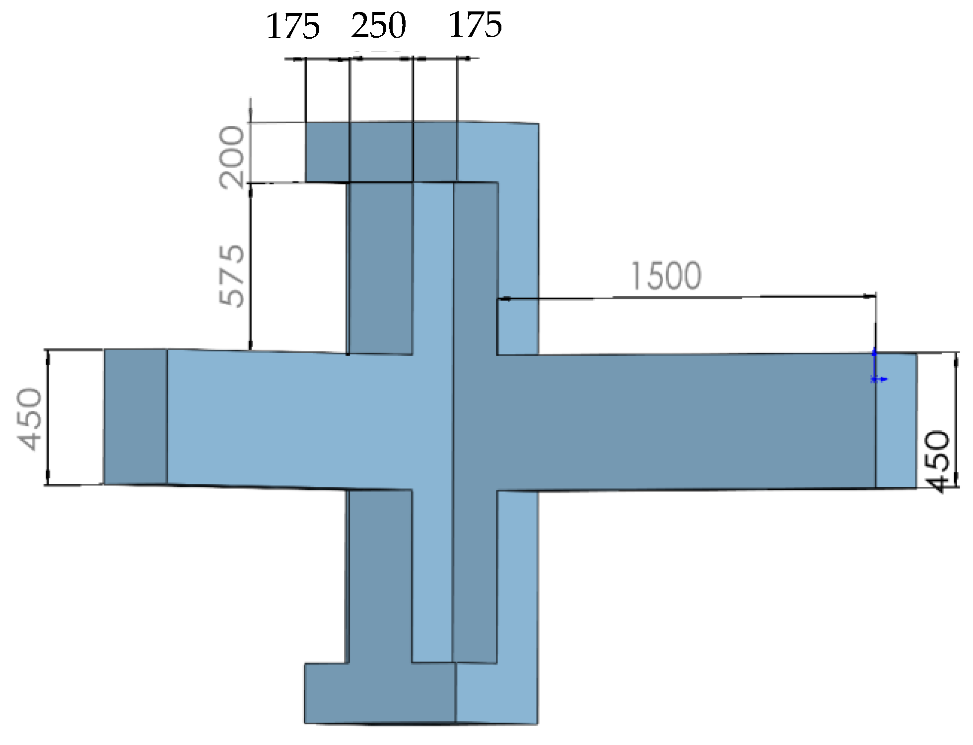
2.1. Materials and Specimens
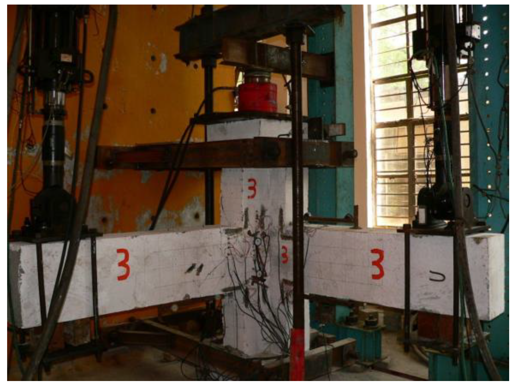
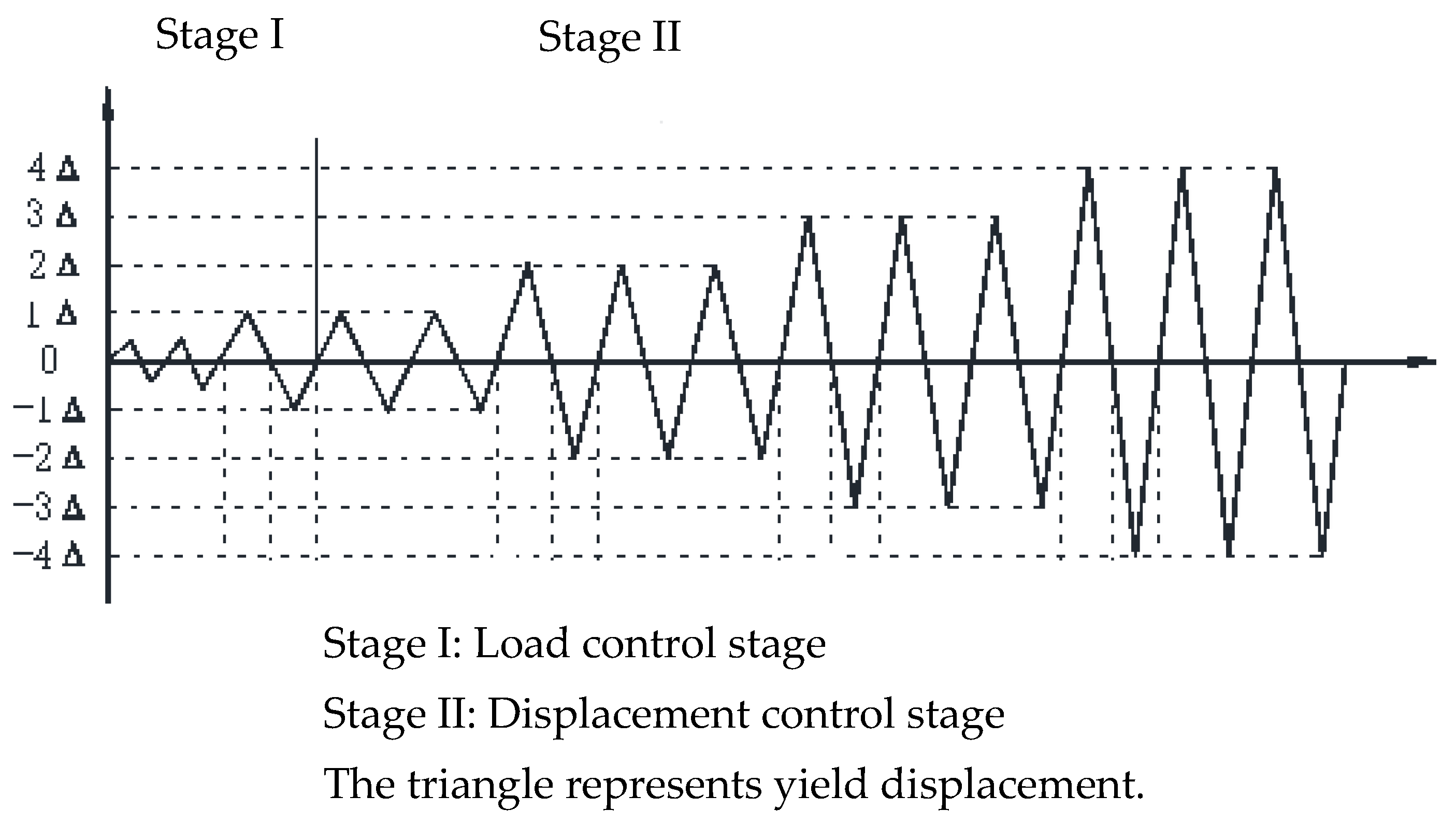
2.2. Loading System and Measurement
3. Test Procedures and Crack Observation
3.1. Specimen JD-1
3.2. Specimen JD-2
3.3. Specimen JD-3
3.4. Specimen JD-4
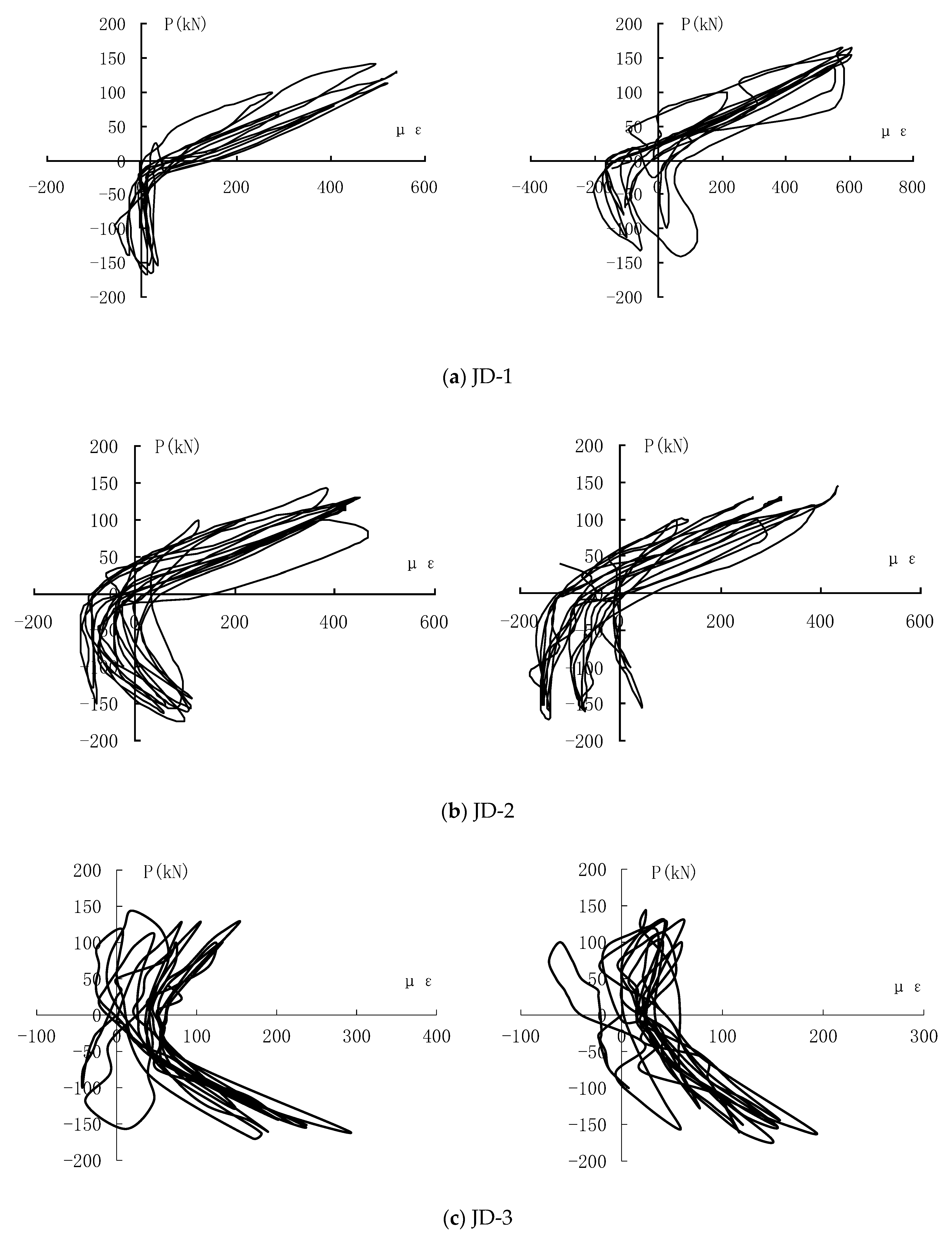
4. Results and Hysteresis Analysis
5. Seismic Energy Dissipation Analysis
6. Conclusions
- The distinctly shaped column design addresses the limitations of conventional frame columns, where their oversized sections and sharp edges often detract from architectural esthetics. Consequently, this innovative structure holds immense potential for extensive application in practical engineering projects. However, distinctly shaped SRC column joints sometimes fall short in terms of mechanical performance, prompting the urgency to investigate and enhance joint design techniques in order to facilitate the wider acceptance and implementation of these cutting-edge designs. This study involved low-frequency cyclic load tests on the proposed distinctly shaped SRC column beam joints, offering a more precise simulation of bidirectional seismic forces compared to conventional unidirectional testing methods. The proposed testing approach offers a marked improvement over conventional unidirectional testing methods, leading to insightful and practical findings that contribute to our understanding of the seismic behavior of SRC joints.
- It was revealed in this investigation that the design approach for distinctly shaped SRC column–beam joints, incorporating steel tubes and structural steel, exhibits remarkable seismic resilience. The I-steel and tubes positioned at the joints exhibit a positive constraining effect on the core concrete, enhancing both the structural integrity and seismic performance of the overall structure. Additionally, the joint proposed in this study demonstrates reduced stiffness degradation, minimal load-bearing capacity deterioration, and superior ductility under bidirectional low-cyclic reversed-loading conditions, indicating its potential for improved seismic performance.
- This study also delineates the progression of crack formation and subsequent structural collapse. It portrays pertinent hysteresis curves and compares the hysteretic behaviors of SRC joints with those of conventional RC joints. This comparison underscores SRC joints’ more complete hysteresis loops, indicative of their superior energy dissipation efficiency and ductility in contrast to RC joints. Additionally, this study explores the strain hysteresis characteristics of structural steel and tubes under operational settings. Conclusively, the incorporation of structural steel and concrete within the core steel tube is found to significantly bolster the load-bearing capacity of joints during seismic events. Looking ahead, future endeavors may involve incorporating finite element analysis to further investigate the energy dissipation mechanisms of SRC joints.
Author Contributions
Funding
Data Availability Statement
Acknowledgments
Conflicts of Interest
References
- Park, R. A summary of results of simulated seismic load tests on reinforced concrete beam-column joints, beams and columns with substandard reinforcing details. J. Earthq. Eng. 2002, 6, 147–174. [Google Scholar] [CrossRef]
- Luo, X.; Cheng, J.; Xiang, P.; Long, H. Seismic behavior of corroded reinforced concrete column joints under low-cyclic repeated loading. Arch. Civ. Mech. Eng. 2020, 20, 40. [Google Scholar] [CrossRef]
- Chen, J.; Chen, X.; Ding, F.; Xiang, P.; Yang, C.; Liu, Y.; Xu, F. Mechanical performance of overlap connections with grout-filled anchor reinforcements in embedded metal corrugated pipe. Arch. Civ. Mech. Eng. 2020, 20, 128. [Google Scholar] [CrossRef]
- Zhang, X.; Xia, Q.; Ye, B.; Yan, W.; Deng, Z.; Xiang, P. Seismic Performances of SRC Special-Shaped Columns and RC Beam Joints Under Double-Direction Low-Cyclic Reversed Loading. Front. Mater. 2021, 8, 761376. [Google Scholar] [CrossRef]
- Xiang, P.; Lin, Y.; Huang, W.; Ding, F.; Ye, B.; Deng, Z. Investigation on Shear Capacity of Joints between Steel Reinforced Concrete Special-Shaped Column and Reinforced Concrete Beam. Front. Mater. 2020, 7, 588296. [Google Scholar] [CrossRef]
- Deng, X.; Wang, S.; Chen, J.; Ding, F.; Zhang, Q.; Xiang, P. Experimental investigation on the effect of local debonding of longitudinal reinforcement on seismic performance of precast concrete columns. J. Build. Eng. 2022, 46, 103131. [Google Scholar] [CrossRef]
- Cao, D.; Liu, J.; Ge, W.; Qian, R. Experimental study on the shear performance of steel-truss-reinforced concrete beam-column joints. Adv. Civ. Eng. 2021, 2021, 5580581. [Google Scholar] [CrossRef]
- Deng, Z.; Xu, C.; Zeng, J.; Wang, H.; Wu, X.; Xiang, P. Seismic performance and shear bearing-capacity of truss SRC beam-column frame joints. Adv. Struct. Eng. 2021, 24, 1311–1325. [Google Scholar] [CrossRef]
- Ma, D.-Y.; Han, L.-H.; Zhao, X.-L. Seismic performance of the concrete-encased CFST column to RC beam joint: Experiment. J. Constr. Steel Res. 2019, 154, 134–148. [Google Scholar] [CrossRef]
- Huang, H.; Hao, R.; Zhang, W.; Huang, M. Experimental study on seismic performance of square RC columns subjected to combined loadings. Eng. Struct. 2019, 184, 194–204. [Google Scholar] [CrossRef]
- Zhang, H.; Guo, J.; Wen, W.; Cui, H. Investigation on the bending and tensile performances of the T-shaped hook-connected structure made of laminated composites and TC4 alloy. Polym. Test. 2019, 80, 106083. [Google Scholar] [CrossRef]
- Chen, Z.; Ning, F.; Chen, J.; Liu, X.; Xu, D. Test on mechanical behavior of SRC L-shaped columns under combined torsion and bending moment. Earthq. Eng. Eng. Vib. 2021, 20, 161–177. [Google Scholar] [CrossRef]
- Chen, Z.; Xu, D.; Xu, J.; Wang, N. Seismic behavior and strength of L-shaped steel reinforced concrete column- concrete beam planar and spatial joints. Steel Compos. Struct. 2021, 39, 337–352. [Google Scholar]
- Feng, Y.; Jiang, L.; Zhou, W.; Han, J.; Zhang, Y.; Nie, L.; Tan, Z.; Liu, X. Experimental investigation on shear steel bars in CRTS II slab ballastless track under low-cyclic reciprocating load. Constr. Build. Mater. 2020, 255, 119425. [Google Scholar] [CrossRef]
- Chun, S.C.; Lee, S.H.; Kang, T.H.K.; Oh, B.; Wallace, J.W. Mechanical anchorage in exterior beam-column joints subjected to cyclic loading. ACI Struct. J. 2007, 104, 102–112. [Google Scholar]
- Karabinis, A.I. Reinforced concrete beam-column joints with lap splices under cyclic loading. Struct. Eng. Mech. 2002, 14, 649–660. [Google Scholar] [CrossRef]
- Metelli, G.; Messali, F.; Beschi, C.; Riva, P. A model for beam-column corner joints of existing RC frame subjected to cyclic loading. Eng. Struct. 2015, 89, 79–92. [Google Scholar] [CrossRef]
- Said, A.M. Damage characterization of beam-column joints reinforced with GFRP under reversed cyclic loading. Smart Struct. Syst. 2009, 5, 443–455. [Google Scholar] [CrossRef]
- Sasmal, S.; Novak, B.; Ramanjaneyulu, K. Numerical analysis of under-designed reinforced concrete beam-column joints under cyclic loading. Comput. Concr. 2010, 7, 203–220. [Google Scholar] [CrossRef]
- Xiang, P.; Deng, Z.H.; Su, Y.S.; Wang, H.P.; Wan, Y.F. Experimental investigation on joints between steel-reinforced concrete T-shaped column and reinforced concrete beam under bidirectional low-cyclic reversed loading. Adv. Struct. Eng. 2017, 20, 446–460. [Google Scholar] [CrossRef]
- Yu, J.; Zhang, W.; Tang, Z.; Guo, X.; Pospisil, S. Seismic behavior of precast concrete beam-column joints with steel strand inserts under cyclic loading. Eng. Struct. 2020, 216, 110766. [Google Scholar] [CrossRef]
- Zhou, J.; Fang, X.; Jiang, Y.; Yang, J. Cyclic experiments on concrete-encased CFST wall-RC coupling beam joints with non-through-core anchorages. J. Earthq. Eng. 2020, 26, 1518–1542. [Google Scholar] [CrossRef]
- Chu, L.; Li, D.; Ma, X.; Zhao, J. Cyclic behaviour of concrete encased steel (CES) column-steel beam joints with concrete slabs. Steel Compos. Struct. 2018, 29, 731–744. [Google Scholar]
- Deng, Z.; Hu, Q.; Zeng, J.; Xiang, P.; Xu, C. Structural performance of steel-truss-reinforced composite joints under cyclic loading. Proc. Inst. Civ. Eng. -Struct. Build. 2018, 171, 130–148. [Google Scholar] [CrossRef]
- Chen, Z.P.; Xu, J.J.; Chen, Y.L.; Xue, J.Y. Seismic behavior of steel reinforced concrete (SRC) T-shaped column-beam planar and 3D hybrid joints under cyclic loads. Earthq. Struct. 2015, 8, 555–572. [Google Scholar] [CrossRef]
- Chen, Z.P.; Xu, J.J.; Xue, J.Y. Hysteretic behavior of special shaped columns composed of steel and reinforced concrete (SRC). Earthq. Eng. Eng. Vib. 2015, 14, 329–345. [Google Scholar] [CrossRef]
- Xu, C.X.; Sheng, P.S.; Wan, C.C. Experimental and theoretical research on shear strength of seismic-damaged SRC frame columns strengthened with enveloped steel jackets. Adv. Civ. Eng. 2019, 2019, 6401730. [Google Scholar] [CrossRef]
- Chu, L.; Li, Q.; Zhao, J.; Li, D. Seismic behavior of hybrid frame joints between composite columns and steel beams. Shock Vib. 2020, 2020, 8870582. [Google Scholar] [CrossRef]
- Chen, J.; Zhao, C.; Ding, F.; Xiang, P. Experimental study on the seismic behavior of precast concrete column with grouted corrugated sleeves and debonded longitudinal reinforcements. Adv. Struct. Eng. 2019, 22, 3277–3289. [Google Scholar] [CrossRef]
- Chen, Z.; Liu, X. Seismic behavior of steel reinforced concrete cross-shaped column under combined torsion. Steel Compos. Struct. 2018, 26, 407–420. [Google Scholar]
- Deng, Z.; Xu, C.; Hu, Q.; Zeng, J.; Xiang, P. Investigation on the structural behavior of shear walls with steel truss coupling beams under seismic loading. Adv. Mater. Sci. Eng. 2018, 2018, 5602348. [Google Scholar] [CrossRef]
- Akduman, S.; Karalar, M.; Mert, N.; Ozturk, H. Investigation of the post-fire behavior of different end-plated beam-column connections. Buildings 2024, 14, 1013. [Google Scholar] [CrossRef]
- Stel’Makh, S.A.; Shcherban, E.M.; Beskopylny, A.N.; Mailyan, L.R.; Veremeenko, A.; Shilov, A.V.; Ananova, O.; Karalar, M.; Aksoylu, C.; Onuralp Özkılıç, Y. Modeling and calculation of improved centrifuged reinforced concrete columns with variotropic structure. Buildings 2023, 13, 2005. [Google Scholar] [CrossRef]
- Karalar, M.; Dicleli, M. Effect of pile orientation on the fatigue performance of jointless bridge H-piles subjected to cyclic flexural strains. Eng. Struct. 2023, 276, 115385. [Google Scholar] [CrossRef]
- Murad, Y.Z.; Alseid, B.H. Retrofitting interior RC beam-to-column joints subjected to quasi-static loading using NSM CFRP ropes. Structures 2021, 34, 4158–4168. [Google Scholar] [CrossRef]
- Zapris, A.G.; Kytinou, V.K.; Gribniak, V.; Chalioris, C.E. Novel approach for strengthening T-beams deficient in shear with near-surface mounted CFRP ropes in form of closed stirrups. Dev. Built Environ. 2024, 18, 100394. [Google Scholar] [CrossRef]
- GB 50010-2002; Code for Design of Concrete Structures. Ministry of Construction of the People’s Republic of China: Beijing, China, 2002.
- GB 50010-2001; Code for Seismic Design of Buildings. Ministry of Construction of the People’s Republic of China: Beijing, China, 2001.


| Symbol | Definition | Unit |
|---|---|---|
| Diameter | ||
| Modulus of elasticity of concrete | (N/mm2) | |
| Concrete axial compressive strength | (N/mm2) | |
| Concrete axial tensile strength | (N/mm2) | |
| Loop rigidity | ||
| Cracking load | ||
| Damage load | ||
| Ultimate load | ||
| Yield load | ||
| Ultimate displacement | ||
| Yield displacement | ||
| Elongation | -- | |
| Ductility factor | -- | |
| Yield strength of steel | (N/mm2) | |
| Ultimate strength of steel | (N/mm2) |
| Specimen | JD-1 | JD-2 | JD-3 | JD-4 | |
|---|---|---|---|---|---|
| Cross-section | Beam (mm × mm) | 250 × 450 | 250 × 450 | 250 × 450 | 250 × 450 |
| Column | T-type | T-type | T-type | T-type | |
| Beam | Longitudinal steel bar | 8B20 | 8B20 | 8B20 | 8B20 |
| Stirrup | |||||
| Column | I-shaped steel | ----- | |||
| Longitudinal steel bar | 12B14 | 12B14 | 12B14 | 12B14 | |
| Stirrup | |||||
| Round steel | ----- | ||||
| Core area | Stirrup |
| Specimen | (N/mm2) | (N/mm2) | (N/mm2) | (N/mm2) |
|---|---|---|---|---|
| JD-1 | 42.87 | 32.58 | 2.35 | 3.32 × 10⁴ |
| JD-2 | 44.92 | 34.14 | 2.42 | 3.36 × 10⁴ |
| JD-3 | 44.58 | 33.88 | 2.41 | 3.36 × 10⁴ |
| JD-4 | 44.95 | 34.16 | 2.42 | 3.36 × 10⁴ |
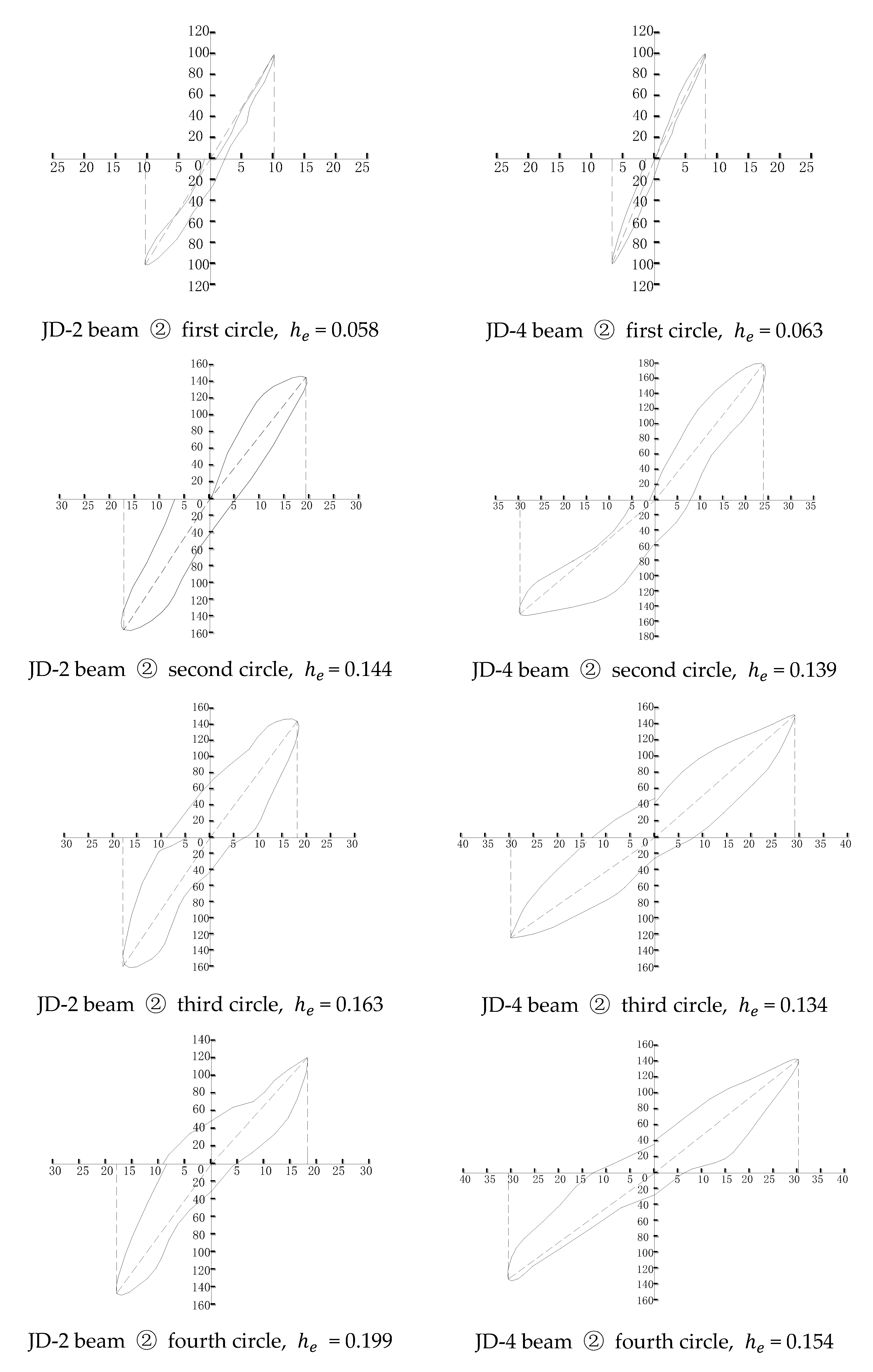
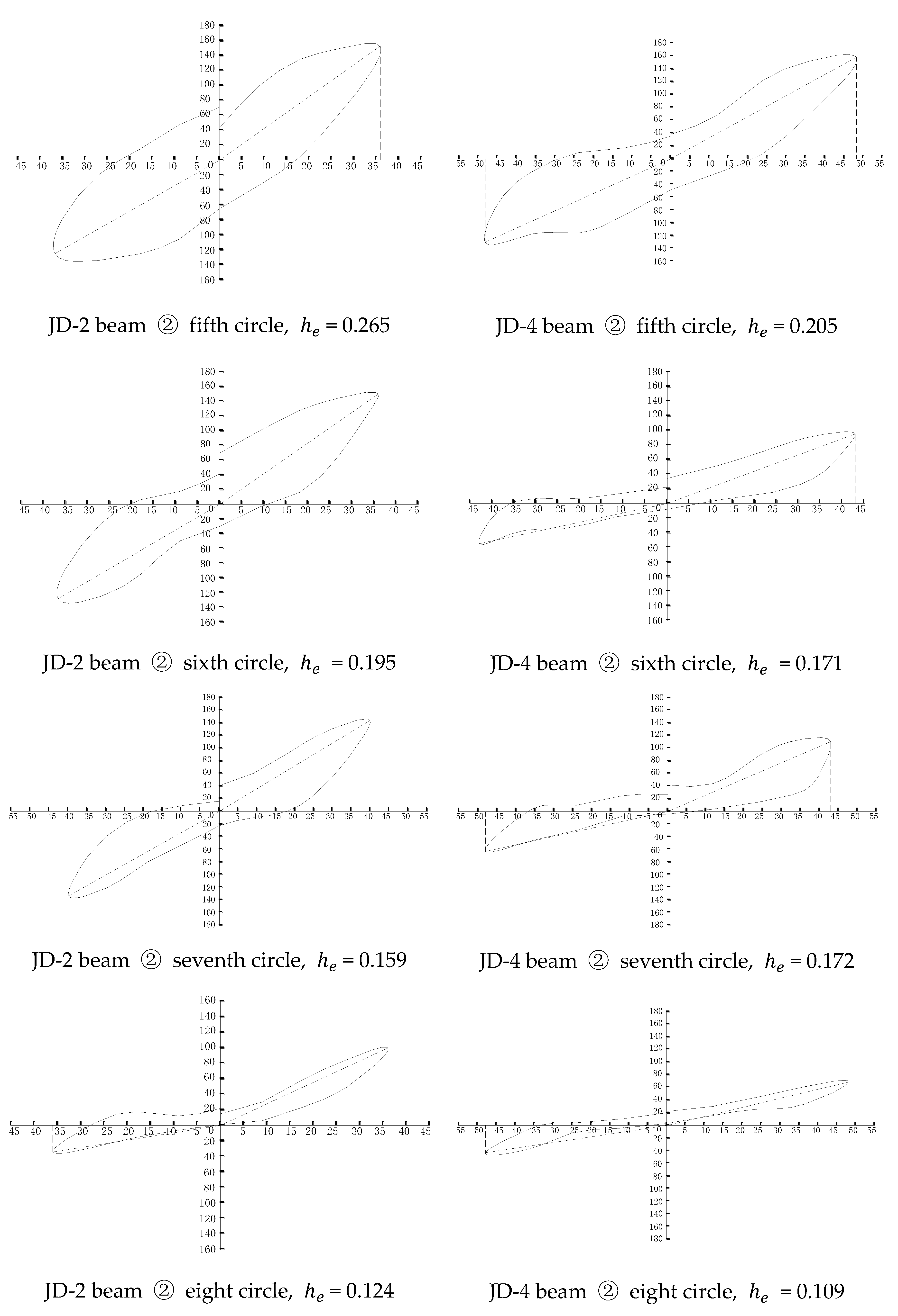
| Specimen No. | Cycle 1 | Cycle 2 | Cycle 3 | Cycle 4 | Cycle 5 | Cycle 6 | Cycle 7 | Cycle 8 |
|---|---|---|---|---|---|---|---|---|
| JD-2 | 0.058 | 0.144 | 0.163 | 0.199 | 0.265 | 0.195 | 0.159 | 0.124 |
| JD-4 | 0.063 | 0.139 | 0.134 | 0.154 | 0.205 | 0.171 | 0.172 | 0.109 |
Disclaimer/Publisher’s Note: The statements, opinions and data contained in all publications are solely those of the individual author(s) and contributor(s) and not of MDPI and/or the editor(s). MDPI and/or the editor(s) disclaim responsibility for any injury to people or property resulting from any ideas, methods, instructions or products referred to in the content. |
© 2024 by the authors. Licensee MDPI, Basel, Switzerland. This article is an open access article distributed under the terms and conditions of the Creative Commons Attribution (CC BY) license (https://creativecommons.org/licenses/by/4.0/).
Share and Cite
Duan, J.; Yang, D.; Liu, X.; Xiang, P. Seismic Energy Dissipation and Hysteresis Performances of Distinctly Shaped Steel-Reinforced Concrete Column–Beam Joints under Cyclic Loading. Buildings 2024, 14, 2777. https://doi.org/10.3390/buildings14092777
Duan J, Yang D, Liu X, Xiang P. Seismic Energy Dissipation and Hysteresis Performances of Distinctly Shaped Steel-Reinforced Concrete Column–Beam Joints under Cyclic Loading. Buildings. 2024; 14(9):2777. https://doi.org/10.3390/buildings14092777
Chicago/Turabian StyleDuan, Junquan, Delei Yang, Xiaochun Liu, and Ping Xiang. 2024. "Seismic Energy Dissipation and Hysteresis Performances of Distinctly Shaped Steel-Reinforced Concrete Column–Beam Joints under Cyclic Loading" Buildings 14, no. 9: 2777. https://doi.org/10.3390/buildings14092777
APA StyleDuan, J., Yang, D., Liu, X., & Xiang, P. (2024). Seismic Energy Dissipation and Hysteresis Performances of Distinctly Shaped Steel-Reinforced Concrete Column–Beam Joints under Cyclic Loading. Buildings, 14(9), 2777. https://doi.org/10.3390/buildings14092777