
Shear Behavior of High-Strength and Lightweight Cementitious Composites Containing Hollow Glass Microspheres and Carbon Nanotubes


Abstract
1. Introduction
2. Research Significance
3. Test Program
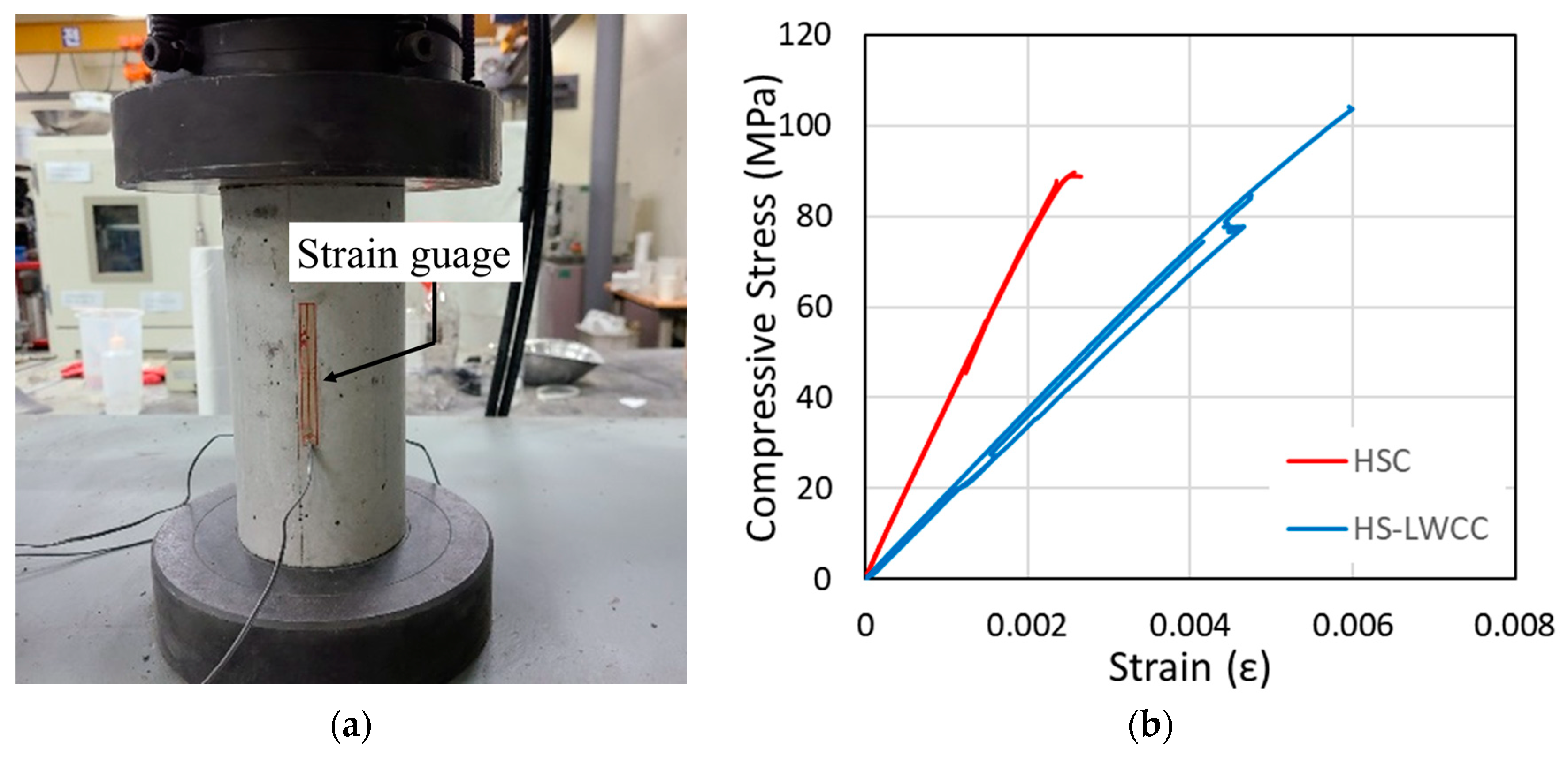
3.1. Materials
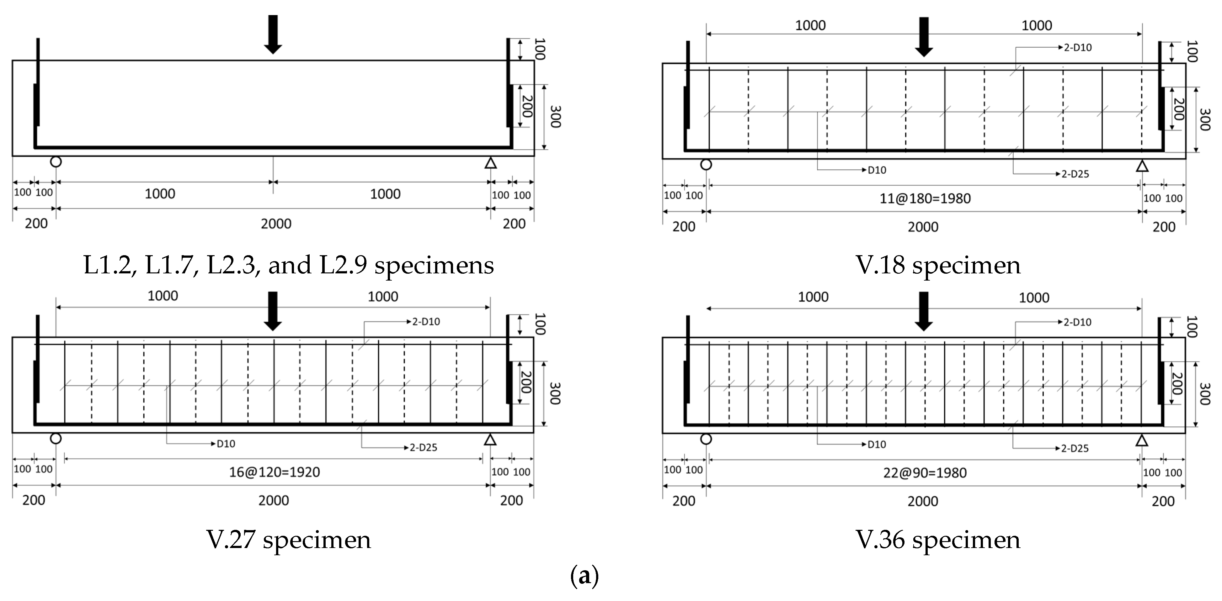
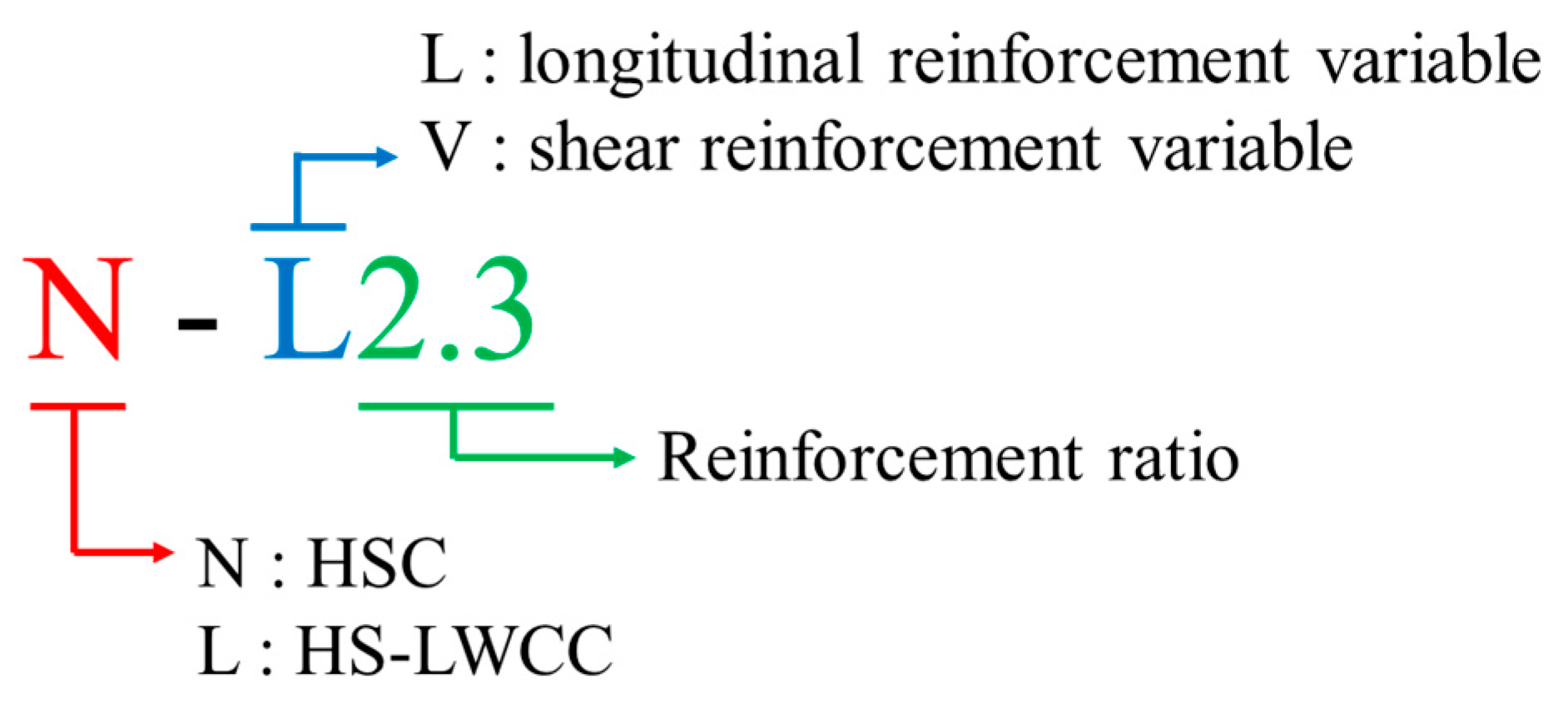
3.2. Design of Beams
3.3. Test Setup
4. Test Results
4.1. Overall Behavior and Failure Mode
4.2. Load–Deflection Responses
4.3. Shear Capacity and Corresponding Deflection
4.4. Average Strain and Diagonal Compression Strut Angle
5. Comparison with Design Provisions
6. Conclusions
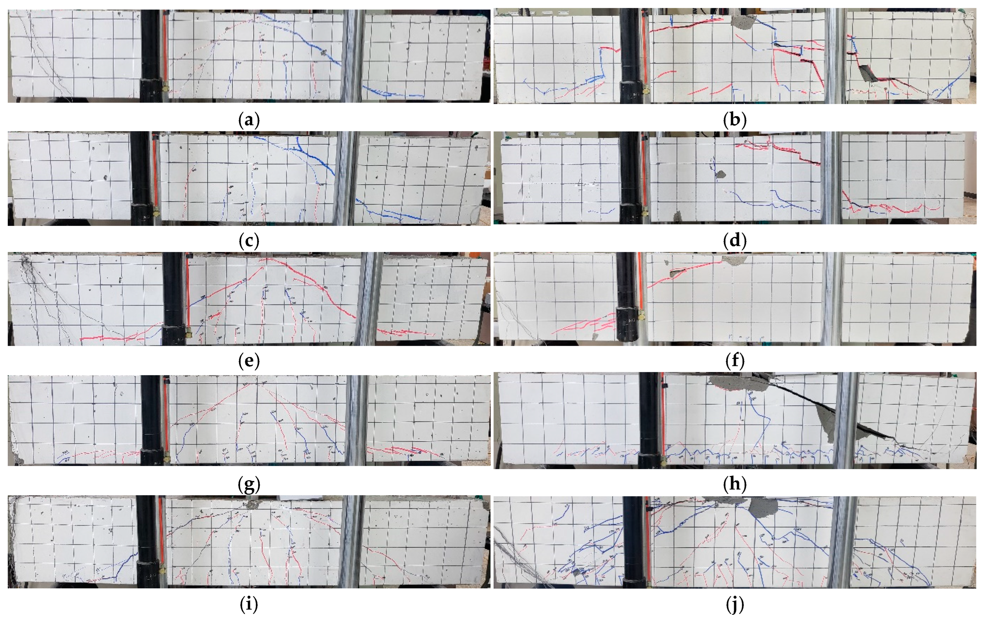
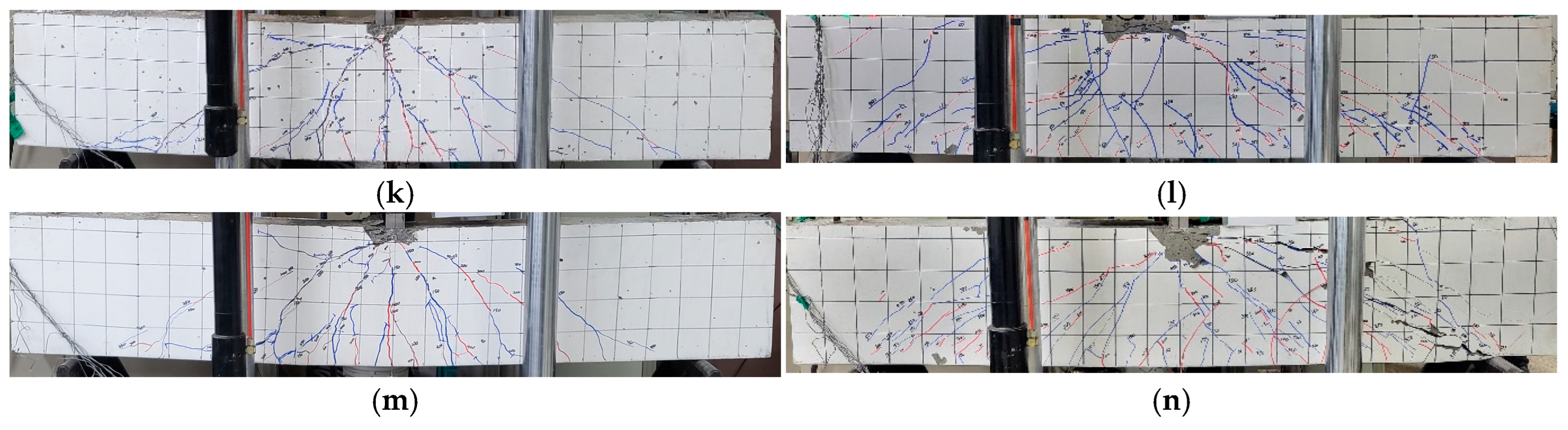
- The shear cracks in the HS-LWCC beams, when compared with those in the HSC beams, appeared straighter. This was attributed to the significantly lower shear resistance of HS-LWCCs along the crack surface. Compared with HSC, HS-LWCCs have a lower tensile strength and aggregate interlocking effect.
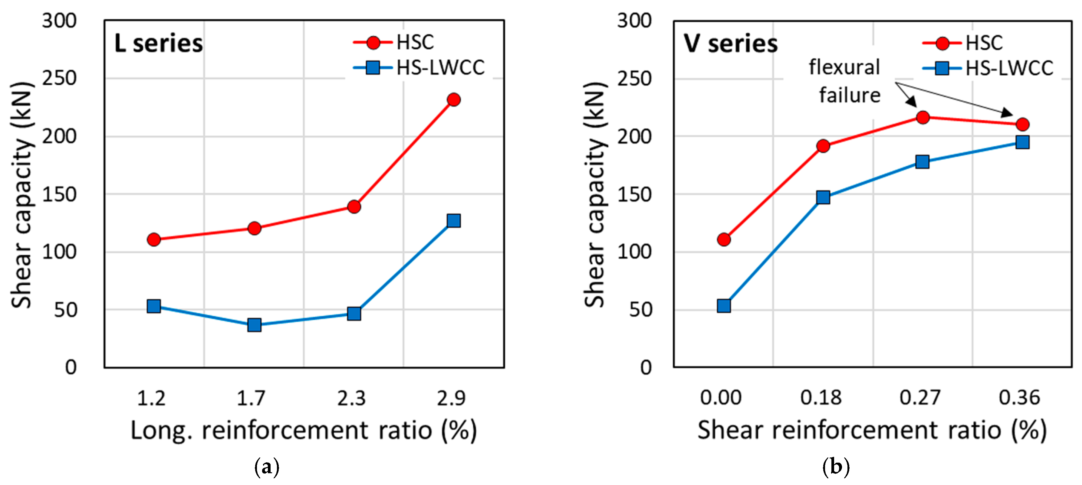
- Without shear reinforcement, the increase in the shear capacity with the longitudinal reinforcement ratio was more distinct in the HS-LWCC beams than in the HSC beams. Meanwhile, when excessive longitudinal reinforcement was provided using D29 bars at a ratio of 2.9%, both the HSC and HS-LWCC beams exhibited a significant increase in their shear capacity.
- In both the HSC and HS-LWCC beams, the shear capacity increased with the shear reinforcement ratio. The HSC beams exhibited flexural failure when the shear reinforcement ratio was 0.27 or 0.36%, whereas the HS-LWCC beams experienced shear failure. This was because the contribution of the concrete to the shear capacity of the HS-LWCC beams was smaller than that to the shear capacity of the HSC beams.
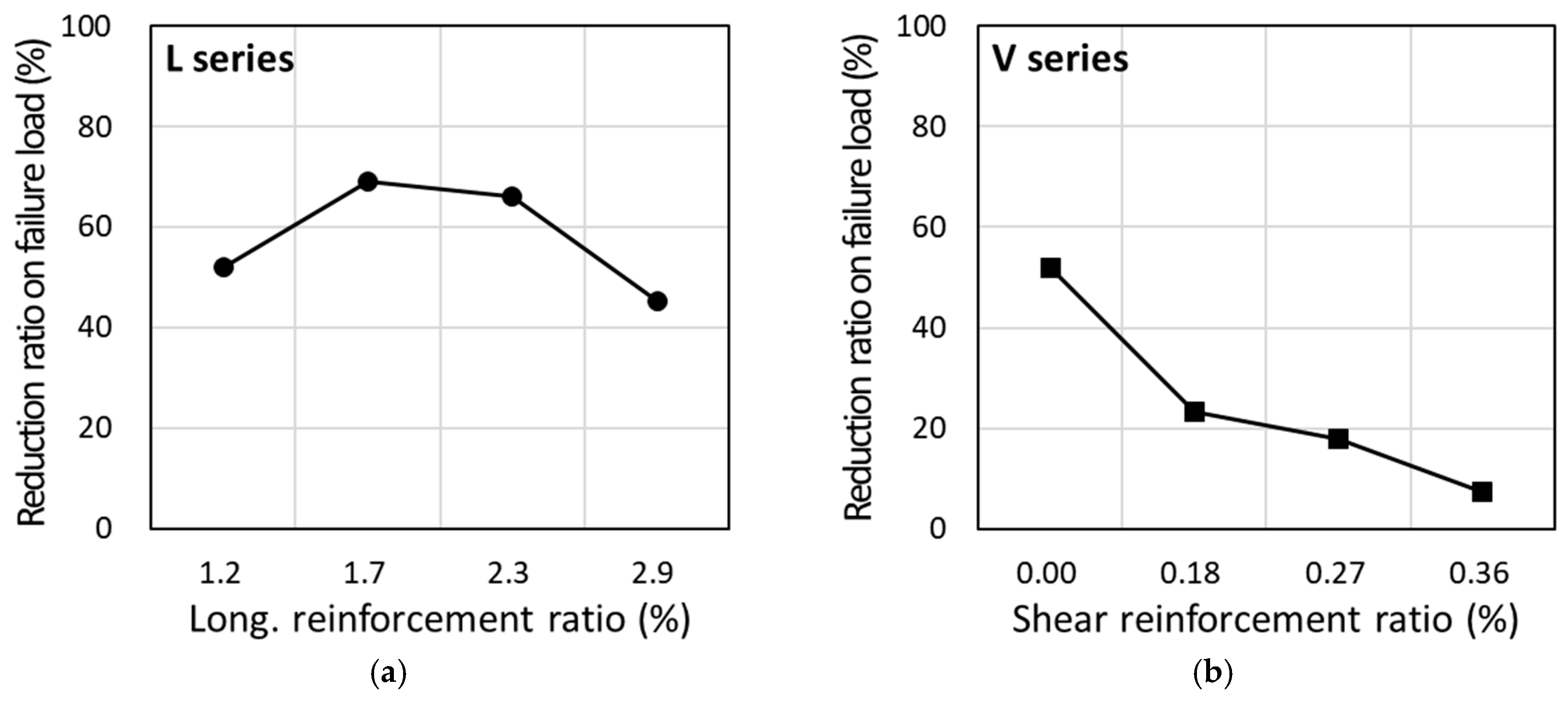
- When comparing the shear capacity of HSC and HS-LWCCs, the shear capacity of the HS-LWCC beams without shear reinforcement showed a reduction of 52%, 69%, 66%, and 45% compared to the HSC beams for L1.2 to L2.9, respectively, at the same longitudinal reinforcement ratio. In the case with shear reinforcement, there was a reduction of 23%, 18%, and 7% for V.18 to V.36, respectively. When shear reinforcement was provided, the difference between the HSC and HS-LWCC beams was not as significant as in the case without shear reinforcement.
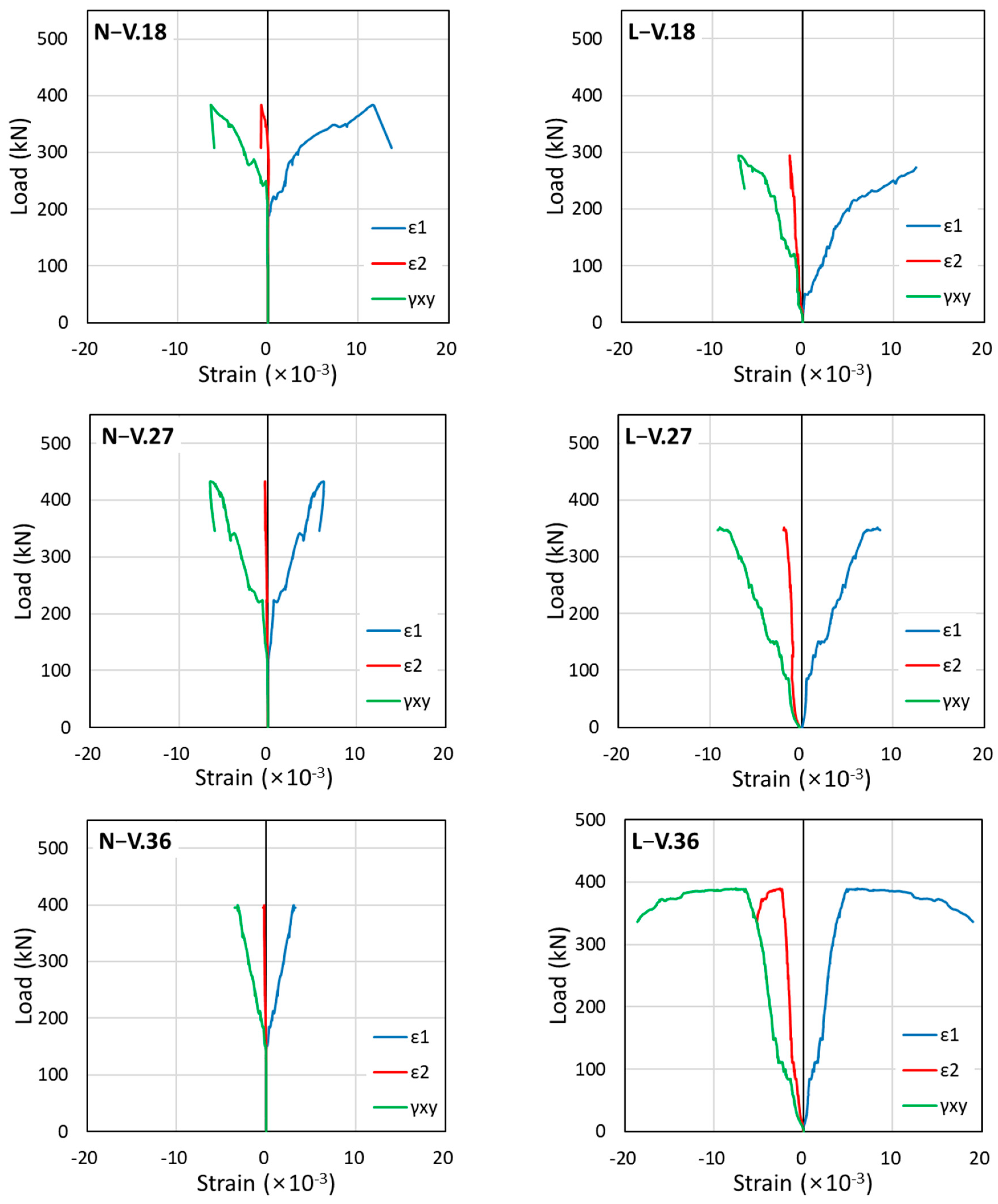
- In the HSC and HS-LWCC beams, the diagonal compression strut inclination angle obtained from the measurements of the LVDT rosette was found to be similar to the inclined shear crack angle. Additionally, the inclined shear crack angle and diagonal compression strut angle were observed to be smaller in the HS-LWCC beams than in the HSC beams. Therefore, the contribution of the shear reinforcement to the HS-LWCC beams was expected to be more considerable than that to the HSC beams.
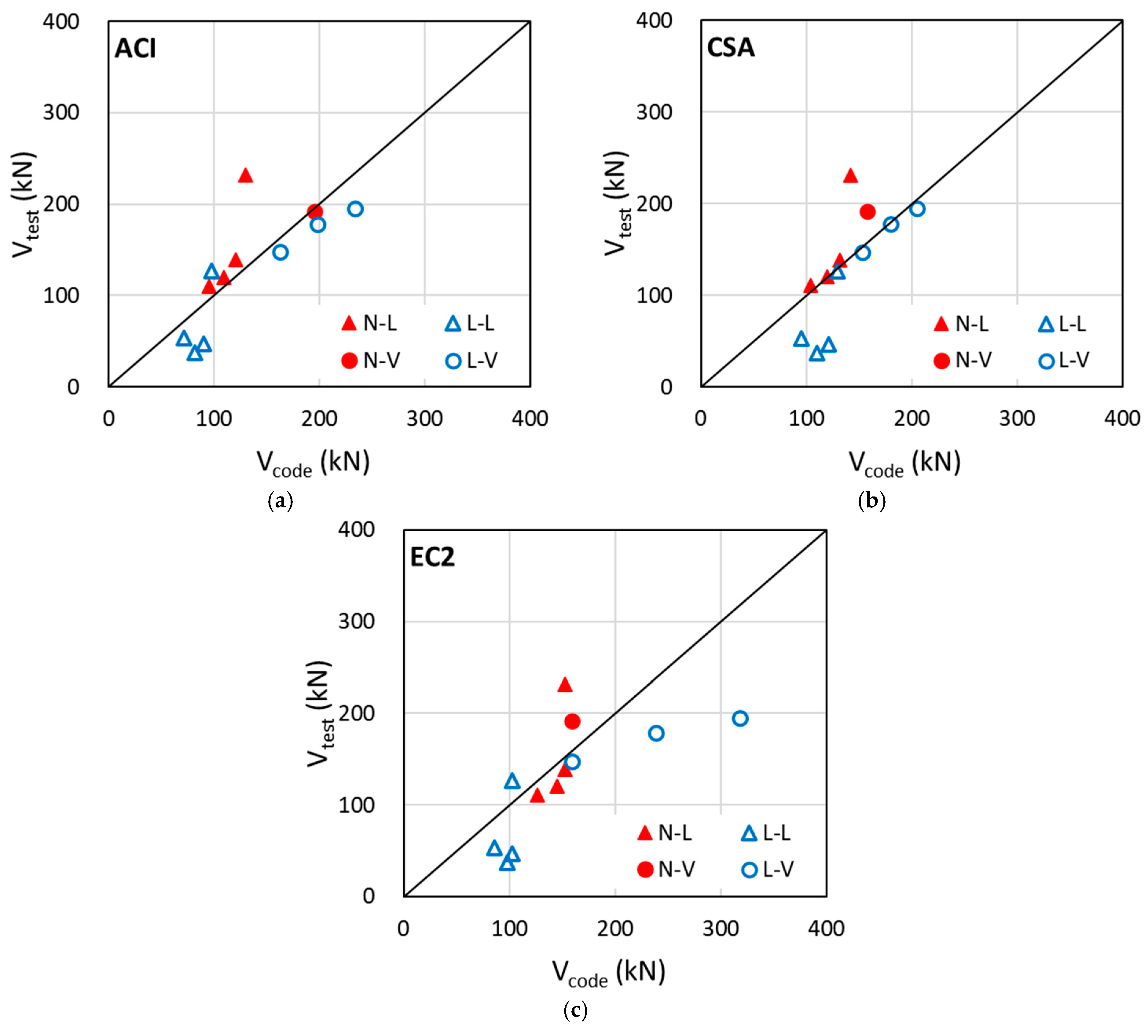
- Current design provisions overestimate the shear capacity of HS-LWCC beams without shear reinforcement compared with that of HSC beams. Therefore, the contribution of concrete to the shear capacity of HS-LWCC beams must be evaluated as lower than the contribution suggested by the current design provisions.
- The provisions of CSA A23.3 were found to predict the shear strength of the HS-LWCC beams with shear reinforcement most accurately. However, when the contribution of concrete to the shear strength of HS-LWCCs is reduced, the shear reinforcement contribution should be evaluated more rationally. The provisions of ACI 318 tended to overestimate the contribution of concrete to the shear capacity of HS-LWCC beams. Conversely, the provisions of EC2 tended to overestimate the shear reinforcement contribution from the small angles of inclined shear cracks. Therefore, for a more reasonable shear design of HS-LWCC beams, the contributions of both the concrete and shear reinforcement must be evaluated more accurately.
- The test results indicate that an HS-LWCC beam tends to require more shear reinforcement than a conventional HSC beam. However, since the dry density of HS-LWCCs is only 63% of that of HSC (1.52 compared to 2.43 t/m3), the self-weight of an HS-LWCC element is significantly lower than that of an HSC element. Consequently, HS-LWCCs are advantageous due to their reduced self-weight, which could result in the smaller dimensions of a reinforced concrete member.
Author Contributions
Funding
Data Availability Statement
Conflicts of Interest
Appendix A

| ACI 318-19 (2019) | ||
| w/o stirrups | ||
| : | ||
| w/ stirrups | ||
| material factor of lightweight concrete, 0.75 | ||
| CSA A23.3:19 (2019) | ||
| material factor of lightweight concrete, 0.75 | ||
| EC2 (2004) | w/o stirrups | |
| : | ||
| w/ stirrups | ||
| for concrete, for lightweight concrete | ||
| for lightweight concrete | ||
| gross area of concrete section, mm2 area of shear reinforcement, mm2 factored axial force normal to cross section, N specified nominal size of coarse aggregate, mm; , if is greater than 70 MPa web width of cross section, mm effective depth, mm effective shear depth, mm; shall be taken as the greater of or specified compressive strength of concrete, MPa specified yield strength of shear reinforcement, MPa maximum size of aggregate, mm aggregate interlocking factor longitudinal spacing of shear reinforcement, MPa crack spacing parameter, mm; shall be taken as or the maximum distance between the layers of distributed longitudinal reinforcement equivalent crack spacing parameter, mm; internal lever arm, mm factor used to account for shear resistance of cracked concrete oven-dry density of lightweight concrete longitudinal reinforcement ratio; angle between web compression and axis of member (°) mid-depth strain at section; , | ||
References
- ACI 318-19; Building Code Requirements for Structural Concrete and Commentary. American Concrete Institute (ACI): Farmington Hills, MI, USA, 2019.
- CAN/CSA-A23.3-19; Design of Concrete Structures. Canadian Standards Association (CSA): Mississauga, ON, Canada, 2019.
- Eurocode 2; Design of Concrete Structures-Part 1-1: General Rules and Rules for Buildings. European Committee for Standardization: London, UK, 2004.
- Raithby, K.D.; Lydon, F.D. Lightweight concrete in highway bridges. Int. J. Cem. Compos. Lightweight Concr. 1981, 3, 133–146. [Google Scholar] [CrossRef]
- Schackow, A.; Effting, C.; Folgueras, M.V.; Güths, S.; Mendes, G.A. Mechanical and thermal properties of lightweight concretes with vermiculite and EPS using air-entraining agent. Constr. Build. Mater. 2014, 57, 190–197. [Google Scholar] [CrossRef]
- Mo, K.H.; Visintin, P.; Alengaram, U.J.; Jumaat, M.Z. Prediction of the structural behaviour of oil palm shell lightweight concrete beams. Constr. Build. Mater. 2016, 102, 722–732. [Google Scholar] [CrossRef]
- Aslani, F.; Ma, G. Normal and high-strength lightweight self-compacting concrete incorporating perlite, scoria, and polystyrene aggregates at elevated temperatures. J. Mater. Civ. Eng. 2018, 30, 04018328. [Google Scholar] [CrossRef]
- Hanif, A.; Lu, Z.; Li, Z. Utilization of fly ash cenosphere as lightweight filler in cement-based composites—A review. Constr. Build. Mater. 2017, 144, 373–384. [Google Scholar] [CrossRef]
- Helmy, S.H.; Tahwia, A.M.; Mahdy, M.G.; Abd Elrahman, M.; Abed, M.A.; Youssf, O. The use of recycled tire rubber, crushed glass, and crushed clay brick in lightweight concrete production: A review. Sustainability 2023, 15, 10060. [Google Scholar] [CrossRef]
- Ghamari, A.; Powęzka, A.; Kytinou, V.K.; Amini, A. An Innovative Fire-Resistant Lightweight Concrete Infill Wall Reinforced with Waste Glass. Buildings 2024, 14, 626. [Google Scholar] [CrossRef]
- Alharthai, M.; OzkiliC, Y.O.; Karalar, M.; Mydin, M.A.O.; Ozdoner, N.; ihsan Celik, A. Performance of aerated lightweighted concrete using aluminum lathe and pumice under elevated temperature. Steel Compos. Struct. 2024, 51, 271. [Google Scholar]
- Mermerdaş, K.; İpek, S.; Algın, Z.; Ekmen, Ş.; GGŞen, İ. Combined effects of microsilica, steel fibre and artificial lightweight aggregate on the shrinkage and mechanical performance of high strength cementitious composite. Constr. Build. Mater. 2020, 262, 120048. [Google Scholar] [CrossRef]
- Cavalline, T.L.; Gallegos, J.; Castrodale, R.W.; Freeman, C.; Liner, J.; Wall, J. Influence of lightweight aggregate concrete materials on building energy performance. Buildings 2021, 11, 94. [Google Scholar] [CrossRef]
- Samson, G.; Phelipot-Mardelé, A.; Lanos, C. A review of thermomechanical properties of lightweight concrete. Mag. Concr. Res. 2017, 69, 201–216. [Google Scholar] [CrossRef]
- Lee, N.; Pae, J.; Kang, S.H.; Kim, H.K.; Moon, J. Development of high strength & lightweight cementitious composites using hollow glass microsphere in a low water-to-cement matrix. Cem. Concr. Compos. 2022, 130, 104541. [Google Scholar]
- Lee, D.; Lee, S.C.; Yoo, S.W. Workability and compressive behavior of PVA-ECC with CNTs. Geomech. Eng. 2022, 29, 311–320. [Google Scholar]
- Konsta-Gdoutos, M.S.; Danoglidis, P.A.; Falara, M.G.; Nitodas, S.F. Fresh and mechanical properties, and strain sensing of nanomodified cement mortars: The effects of MWCNT aspect ratio, density and functionalization. Cem. Concr. Compos. 2017, 82, 137–151. [Google Scholar] [CrossRef]
- Han, Y.; Shao, S.; Fang, B.; Shi, T.; Zhang, B.; Wang, X.; Zhao, X. Chloride ion penetration resistance of matrix and interfacial transition zone of multi-walled carbon nanotube-reinforced concrete. J. Build. Eng. 2023, 72, 106587. [Google Scholar] [CrossRef]
- Sedaghatdoost, A.; Behfarnia, K.; Bayati, M. The effect of curing period on the residual strength of Portland cement mortar containing MWCNTs at elevated temperature. Constr. Build. Mater. 2019, 196, 144–153. [Google Scholar] [CrossRef]
- Evangelista, A.C.J.; de Morais, J.F.; Tam, V.; Soomro, M.; Di Gregorio, L.T.; Haddad, A.N. Evaluation of carbon nanotube incorporation in cementitious composite materials. Materials 2019, 12, 1504. [Google Scholar] [CrossRef]
- Homma, Y.; Chiashi, S.; Yamamoto, T.; Kono, K.; Matsumoto, D.; Shitaba, J.; Sato, S. Photoluminescence measurements and molecular dynamics simulations of water adsorption on the hydrophobic surface of a carbon nanotube in water vapor. Phys. Rev. Lett. 2013, 110, 157402. [Google Scholar] [CrossRef]
- Jeong, Y.; Kim, J.H.; Moon, J.; Jung, S. Development of lightweight and high-strength cement composites using hollow microsphere and its property improvement throught CNT-dispersed suspension. Mag. Korea Concr. Inst. 2022, 34, 72–77. (In Korean) [Google Scholar]
- Hong, S.-H.; Lee, O.-S.; Lee, H.-J.; Yoon, Y.-S. Evaluation of Flexural Strength of High-Strength Lightweight Cement Composites containing Carbon Nanotubes. J. Korean Soc. Hazard Mitig. 2023, 23, 1–9. (In Korean) [Google Scholar] [CrossRef]
- Hanson, J.A. Shear strength of lightweight reinforced concrete beams. J. Proc. 1958, 55, 387–403. [Google Scholar]
- Yang, K.H.; Sim, J.I.; Choi, B.J.; Lee, E.T. Effect of aggregate size on shear behavior of lightweight concrete continuous slender beams. ACI Mater. J. 2011, 108, 501. [Google Scholar]
- Li, C.; Liang, N.; Zhao, M.; Yao, K.; Li, J.; Li, X. Shear performance of reinforced concrete beams affected by satisfactory composite-recycled aggregates. Materials 2020, 13, 1711. [Google Scholar] [CrossRef]
- Aci-Asce Committee 426. The shear strength of reinforced concrete members. J. Struct. Eng. 1973, 99, 1091–1187. [Google Scholar]
- Cavagnis, F.; Ruiz, M.F.; Muttoni, A. Shear failures in reinforced concrete members without transverse reinforcement: An analysis of the critical shear crack development on the basis of test results. Eng. Struct. 2015, 103, 157–173. [Google Scholar] [CrossRef]
- Bentz, E.C.; Vecchio, F.J.; Collins, M.P. Simplified modified compression field theory for calculating shear strength of reinforced concrete elements. ACI Struct. J. 2006, 103, 614. [Google Scholar]
- Lee, S.-C.; Cho, J.Y.; Oh, B.H. Shear Behavior of Large-Scale Post-Tensioned Girders with Small Shear Span-Depth Ratio. ACI Struct. J. 2010, 107, 27. [Google Scholar]
- ASTM C496/C496M-11; ASTM C496-11 Standard Test Method for Splitting Tensile Strength of Cylindrical Concrete Specimens. Annual Book of ASTM Standard Vol. 04.02 1–5; ASTM International: West Conshohocken, PA, USA, 2011.
- Lee, J.Y.; Choi, I.J.; Kim, S.W. Shear Behavior of Reinforced Concrete Beams with High-Strength Stirrups. ACI Struct. J. 2011, 108, 620–629. [Google Scholar]
- Baby, F.; Marchand, P.; Toutlemonde, F. Shear behavior of ultrahigh performance fiber-reinforced concrete beams. I: Experimental investigation. J. Struct. Eng. 2014, 140, 04013111. [Google Scholar] [CrossRef]
- Trindade, J.C.; Garcia, S.L.; Lacerda, T.N.; Resende, T.L. Analysis of the shear behavior of reinforced recycled aggregate concrete beams based on shear transfer mechanisms. Eng. Struct. 2023, 293, 116616. [Google Scholar] [CrossRef]
- Vecchio, F.J.; Collins, M.P. The modified compression-field theory for reinforced concrete elements subjected to shear. ACI J. 1986, 83, 219–231. [Google Scholar]
- Lee, J.-Y.; Kim, S.W.; Mansour, M.Y. Nonlinear analysis of shear-critical reinforced concrete beams using fixed angle theory. J. Struct. Eng. 2011, 137, 1017–1029. [Google Scholar] [CrossRef]
- Lee, J.-Y.; Shin, D.K.; Kim, K.S.; Kim, S.-W.; Lee, D.; Hwang, H.-J. Shear strength evaluation by variable crack angle (II) design strength of shear reinforcement. J. Korea Concr. Inst. 2023, 35, 367–377. (In Korean) [Google Scholar] [CrossRef]
- Jeli, I.; Pavlović, M.N.; Kotsovos, M.D. A study of dowel action in reinforced concrete beams. Mag. Concr. Res. 1999, 51, 131–141. [Google Scholar] [CrossRef]
- Han, S.J.; Lee, D.; Yi, S.T.; Kim, K.S. Experimental shear tests of reinforced concrete beams with corroded longitudinal reinforcement. Struct. Concr. 2020, 21, 1763–1776. [Google Scholar] [CrossRef]
- Cui, H.Z.; Lo, T.Y.; Memon, S.A.; Xu, W. Effect of lightweight aggregates on the mechanical properties and brittleness of lightweight aggregate concrete. Constr. Build. Mater. 2012, 35, 149–158. [Google Scholar] [CrossRef]
- Autrup, F.; Jørgensen, H.B.; Hoang, L.C. Experimental investigation of dowel action in RC beams without shear reinforcement. In Proceedings of the Fib Symposium 2020: Concrete Structures for Resilient Society, Shanghai, China, 22–24 November 2020; pp. 540–548. [Google Scholar]
- Baumann, T.; Rüsch, H. Tests on dowelling action of flexural reinforcement of reinforced concrete beams. Dtsch. Ausscuss Für Stahlbeton 1970, 210, 42–83. [Google Scholar]
- Vintzeleou, E.N.; Tassios, T.P. Behavior of dowels under cyclic deformations. ACI Struct. J. 1987, 84, 18–30. [Google Scholar]
- Cavagnis, F.; Ruiz, M.F.; Muttoni, A. A mechanical model for failures in shear of members without transverse reinforcement based on development of a critical shear crack. Eng. Struct. 2018, 157, 300–315. [Google Scholar] [CrossRef]
- Kockal, N.U.; Ozturan, T. Strength and elastic properties of structural lightweight concretes. Mater. Des. 2011, 32, 2396–2403. [Google Scholar] [CrossRef]
- Zhou, F.P.; Balendran, R.V.; Jeary, A.P. Size effect on flexural, splitting tensile, and torsional strengths of high-strength concrete. Cem. Concr. Res. 1998, 28, 1725–1736. [Google Scholar] [CrossRef]


| Type | W/B 1 | C 2 | FA 3 | Silica Fume | Silica Powder | Aggregate | Lightweight Materials | SP 6 | W 7 | CNTs (wt.%) | ||
|---|---|---|---|---|---|---|---|---|---|---|---|---|
| Coarse | Fine | LA 4 | HGMs 5 | |||||||||
| HSC | 0.22 | 542.0 | 70.0 | 83.0 | - | 920.0 | 661.0 | - | - | 10.3 | 153.0 | - |
| HS-LWCC | 0.25 | 739.1 | - | 110.9 | 208.0 | - | - | 111.0 | 211.0 | 25.3 | 212.5 | 0.05 |
| Specimen | a | b | d | h | Longitudinal Reinforcement | Shear Reinforcement | Shear Capacity (kN) | Deflection (mm) | Failure Mode | ||
|---|---|---|---|---|---|---|---|---|---|---|---|
| (%) | (MPa) | (%) | (MPa) | ||||||||
| N-L1.2 | 1000 | 220 | 400 | 440 | 1.16 | 446 | - | - | 110.6 | 4.2 | Shear |
| N-L1.7 | 1000 | 220 | 400 | 440 | 1.74 | 446 | - | - | 120.2 | 2.4 | Shear |
| N-L2.3 | 1000 | 220 | 400 | 440 | 2.32 | 446 | - | - | 139.1 | 3.1 | Shear |
| N-L2.9 | 1000 | 220 | 400 | 440 | 2.93 | 485 | - | - | 231.6 | 6.5 | Shear |
| N-V.18 | 1000 | 220 | 400 | 440 | 1.16 | 446 | 0.18 | 449 | 192.0 | 9.3 | Shear |
| N-V.27 | 1000 | 220 | 400 | 440 | 1.16 | 446 | 0.27 | 449 | 216.6 | 27.9 | Flexure |
| N-V.36 | 1000 | 220 | 400 | 440 | 1.16 | 446 | 0.36 | 449 | 210.5 | 29.8 | Flexure |
| L-L1.2 | 1000 | 220 | 400 | 440 | 1.16 | 446 | - | - | 53.2 | 4.2 | Shear |
| L-L1.7 | 1000 | 220 | 400 | 440 | 1.74 | 446 | - | - | 37.1 | 2.4 | Shear |
| L-L2.3 | 1000 | 220 | 400 | 440 | 2.32 | 446 | - | - | 47.0 | 3.1 | Shear |
| L-L2.9 | 1000 | 220 | 400 | 440 | 2.93 | 485 | - | - | 126.8 | 6.5 | Shear |
| L-V.18 | 1000 | 220 | 400 | 440 | 1.16 | 446 | 0.18 | 449 | 147.2 | 12.1 | Shear |
| L-V.27 | 1000 | 220 | 400 | 440 | 1.16 | 446 | 0.27 | 449 | 177.9 | 12.1 | Shear |
| L-V.36 | 1000 | 220 | 400 | 440 | 1.16 | 446 | 0.36 | 449 | 194.9 | 17.8 | Shear |
| Specimen | Actual Crack Angle (°) | LVDTs Rosette (°) | Actual Crack Angle/ LVDTs Rosette |
|---|---|---|---|
| N-V.18 | 34 | 26 | 1.30 |
| N-V.27 * | 35 | 40 | 0.87 |
| N-V.36 * | 35 | 38 | 0.93 |
| L-V.18 | 27 | 25 | 1.08 |
| L-V.27 | 32 | 28 | 1.16 |
| L-V.36 * | 25 | 32 | 0.78 |
| average | 1.02 | ||
| Specimen | |||||||
|---|---|---|---|---|---|---|---|
| (kN) | (kN) | (kN) | ACI | CSA | EC2 | ||
| N-L1.2 | 110.6 | 95.7 | 103.5 | 127.0 | 1.16 | 1.07 | 0.87 |
| N-L1.7 | 120.2 | 109.5 | 119.7 | 145.3 | 1.10 | 1.00 | 0.83 |
| N-L2.3 | 139.1 | 120.6 | 131.8 | 152.3 | 1.15 | 1.06 | 0.91 |
| N-L2.9 | 231.6 | 130.2 | 141.6 | 152.3 | 1.78 | 1.64 | 1.52 |
| N-V.18 | 192.0 | 195.1 | 157.4 | 159.4 | 0.98 | 1.22 | 1.20 |
| N-V.27 | 216.6 | flexural failure | |||||
| N-V.36 | 210.5 | flexural failure | |||||
| L-L1.2 | 53.2 | 71.8 | 95.4 | 85.6 | 0.74 | 0.56 | 0.62 |
| L-L1.7 | 37.1 | 82.1 | 109.9 | 98.0 | 0.45 | 0.34 | 0.38 |
| L-L2.3 | 47.0 | 90.4 | 120.6 | 102.7 | 0.52 | 0.39 | 0.46 |
| L-L2.9 | 126.8 | 97.7 | 129.3 | 102.7 | 1.30 | 0.98 | 1.23 |
| L-V.18 | 147.2 | 163.2 | 153.7 | 159.4 | 0.90 | 0.96 | 0.92 |
| L-V.27 | 177.9 | 198.6 | 180.4 | 239.1 | 0.90 | 0.99 | 0.74 |
| L-V.36 | 194.9 | 234.1 | 205.5 | 318.8 | 0.83 | 0.95 | 0.61 |
| Average | 0.98 | 0.93 | 0.86 | ||||
| CoV | 0.36 | 0.39 | 0.39 | ||||
Disclaimer/Publisher’s Note: The statements, opinions and data contained in all publications are solely those of the individual author(s) and contributor(s) and not of MDPI and/or the editor(s). MDPI and/or the editor(s) disclaim responsibility for any injury to people or property resulting from any ideas, methods, instructions or products referred to in the content. |
© 2024 by the authors. Licensee MDPI, Basel, Switzerland. This article is an open access article distributed under the terms and conditions of the Creative Commons Attribution (CC BY) license (https://creativecommons.org/licenses/by/4.0/).
Share and Cite
Lee, D.; Lee, S.-C.; Kwon, O.-S.; Yoo, S.-W. Shear Behavior of High-Strength and Lightweight Cementitious Composites Containing Hollow Glass Microspheres and Carbon Nanotubes. Buildings 2024, 14, 2824. https://doi.org/10.3390/buildings14092824
Lee D, Lee S-C, Kwon O-S, Yoo S-W. Shear Behavior of High-Strength and Lightweight Cementitious Composites Containing Hollow Glass Microspheres and Carbon Nanotubes. Buildings. 2024; 14(9):2824. https://doi.org/10.3390/buildings14092824
Chicago/Turabian StyleLee, Dongmin, Seong-Cheol Lee, Oh-Sung Kwon, and Sung-Won Yoo. 2024. "Shear Behavior of High-Strength and Lightweight Cementitious Composites Containing Hollow Glass Microspheres and Carbon Nanotubes" Buildings 14, no. 9: 2824. https://doi.org/10.3390/buildings14092824
APA StyleLee, D., Lee, S.-C., Kwon, O.-S., & Yoo, S.-W. (2024). Shear Behavior of High-Strength and Lightweight Cementitious Composites Containing Hollow Glass Microspheres and Carbon Nanotubes. Buildings, 14(9), 2824. https://doi.org/10.3390/buildings14092824