Article

Investigation into the Operating Performance of a Novel Direct Expansion-Based Air Conditioning System

by
Liu Yang
1,*,
Xiang Zhao
1,
Haitao Wang
1,
Wenfeng Bi
1 and
Shengnan Liu
2
1
College of Civil Engineering and Architecture, Henan University of Technology, Zhengzhou 450001, China
2
School of Thermal Engineering, Shandong Jianzhu University, Jinan 250101, China
*
Author to whom correspondence should be addressed.
Buildings 2024, 14(9), 2846; https://doi.org/10.3390/buildings14092846
Submission received: 31 July 2024 / Revised: 3 September 2024 / Accepted: 9 September 2024 / Published: 10 September 2024
(This article belongs to the Special Issue Heat Pump Systems and Thermal Technology for Buildings)

Abstract

:
This study introduces a novel direct expansion air conditioning (DX AC) system with three evaporators (DX-TE) to enhance indoor temperature and humidity control. Operating in two modes, the DX-TE system provides variable cooling output, adapting to fluctuating indoor cooling loads while maintaining uniform air supply. Experimental and simulation studies were conducted to investigate the system’s operational characteristics. An experimental setup was established to obtain preliminary steady-state data, followed by the development and validation of a steady-state mathematical model. Simulation studies were then performed to optimize the evaporator sizes. The results indicate that the DX-TE system delivers variable cooling capacities at a constant compressor speed and airflow rate, outperforming conventional variable frequency DX AC systems in cooling and dehumidification. The evaporator area ratio significantly impacts the system’s performance, with smaller ratios yielding a larger output range. As the area ratio increases from 1:1 to 1:3, the cooling capacity range in Modes 1 and 2 increases by 33.6% and 14.3%, respectively, while the dehumidification range expands by 58.6% and 51.69%.

1. Introduction

The pivotal role of indoor air temperature (Ti,a) and humidity (RHi,a) regulation in buildings is increasingly recognized [1]. In the context of office and residential buildings, suboptimal indoor air conditions can impair work efficiency [2] and potentially impact health [3]. Similarly, in the specialized environment of chip-manufacturing clean rooms, stringent temperature and humidity control is essential to maintain product yield [4]. Furthermore, modern grain storage facilities necessitate rigorous control of internal air conditions to ensure the long-term preservation of grain quality [5].
Currently, the primary method for indoor environment control in a variety of buildings is through air conditioning systems [6]. The direct-expansion air conditioning (DX AC) system, characterized by its simplistic design, versatility, and high energy efficiency, has found widespread application [7], particularly in small to medium-sized buildings. This has prompted extensive research into optimizing the use of DX AC systems for indoor climate control [8].
DX AC systems, commonly equipped with fixed-frequency compressors, exhibit limited regulatory capabilities [9]. These systems primarily modulate Ti,a through compressor cycling, with no direct control over RHi,a. To address this limitation, Ling et al. [10] pioneered a study on a DX AC system comprising two parallel subsystems, each operating at distinct evaporation temperatures. The system leverages a low-temperature evaporator to manage indoor latent heat and a high-temperature evaporator to handle sensible heat, thereby achieving Ti,a and RHi,a control [11]. In a separate development, Han et al. [12] engineered an isothermal dehumidification system featuring two series-connected evaporators within the room. A valve-switching mechanism allows one of the evaporators to function as a condenser, reheating the air. Further innovation by Fan et al. [13] led to the proposal of a versatile DX AC system capable of operating under multiple conditions. This system incorporates two parallel condensers, with the fan air volume modulating the output of cooling capacity and dehumidification, offering variable control.
In the quest to understand the intricacies of system configurations, scholars have frequently employed supplementary apparatus into the DX AC system to regulate Ti,a and RHi,a. One such approach involves the use of distinct dehumidification equipment [14] to facilitate indoor dehumidification. Alternatively, a reheat coil is utilized to reheat the air treated by the air conditioner evaporator, thereby attaining the desired state of supply air [15]. Despite their utility, these methods are somewhat limited in their effectiveness and tend to consume excessive energy. A significant proportion of indoor latent heat originates from fresh air. To enhance energy efficiency, researchers have explored fresh air treatment systems that operate in conjunction with the DX AC system. These systems process latent heat using either solid [16] or liquid [17] drying subsystems. Concurrently, a separate AC system is employed to handle the indoor sensible heat, thereby achieving control over temperature and humidity. Several fresh air treatment systems have been developed along similar lines. For instance, Zhang et al. [18] utilized two compression cycles and leveraged the combined use of indoor and outdoor coils of the DX AC system to efficiently process fresh air. In another innovative approach, Li et al. [19] integrated the DX system with radiant cooling. By using the VRF system, they were able to separately process outdoor fresh air and indoor air, thereby achieving control over Ti,a and RHi,a.
The advent of variable speed technology has ushered in a new era of integration with DX AC systems [20]. Scholars have discovered that simultaneous frequency conversion operation of the compressor and fan can yield variable outputs for cooling or dehumidification [21]. Building on this discovery, Li et al. [22] and Xu et al. [23] embarked on comprehensive experimental and simulation studies to elucidate the operational characteristics of typical variable-speed direct-expansion air conditioning (VS-DX AC) systems, thereby uncovering the dynamics of system output [24]. Leveraging these insights, Xu et al. [25] employed a two-speed adjustment of the compressor and fan, achieving direct temperature control and indirect humidity control via a straightforward high-low control mechanism. Extending this approach, Yan et al. [26] successfully implemented Ti,a and RHi,a control across multiple rooms. In a novel approach, Li et al. [27] trained the system characteristics and developed a new control algorithm using the ANN model. Their experimental validation confirmed the achievement of Ti,a and RHi,a control. Similarly, Yan et al. [28] developed a unique fuzzy control algorithm rooted in the operational characteristic map of the VS-DX AC system. Experimental validation underscored the reliability of their algorithm.
The review above highlights that current research on regulating Ti,a and RHi,a using DX AC systems identifies two main methodologies: hardware modifications and control algorithms. Hardware modifications involve adding equipment or altering the system’s structure for variable cooling output, while control algorithms coordinate the compressor and fan to adjust Ti,a and RHi,a [29]. Both approaches have limitations in small to medium-sized buildings. Hardware modifications increase system complexity and require additional space, making them unsuitable for high-rise buildings. Control algorithms may cause fluctuations in air volume and supply air temperature, disrupting air distribution and affecting the indoor thermal environment [30]. Further research is needed to address these challenges and optimize DX AC systems for various architectural contexts.
This study addresses the identified limitations of existing DX AC systems by introducing a novel system that incorporates three evaporators. Specifically, a DX AC system with three evaporators (DX-TE) is proposed, which leverages a constant compressor speed and air supply volume to deliver variable cooling output. This design strategy ensures the effective distribution of indoor airflow and the maintenance of an optimal thermal environment, all while facilitating control of Ti,a and RHi,a. The structure of this paper is as follows: Initially, the paper introduces the innovative DX-TE system and presents the construction of its steady-state mathematical model. Subsequently, an experimental platform for the system is established to conduct empirical investigations and validate the mathematical model. Following this, the mathematical model is employed to optimize the system structure. Finally, conclusions are given.

2. Details of the Proposed DX-TE System and Development of Its Steady-State Model

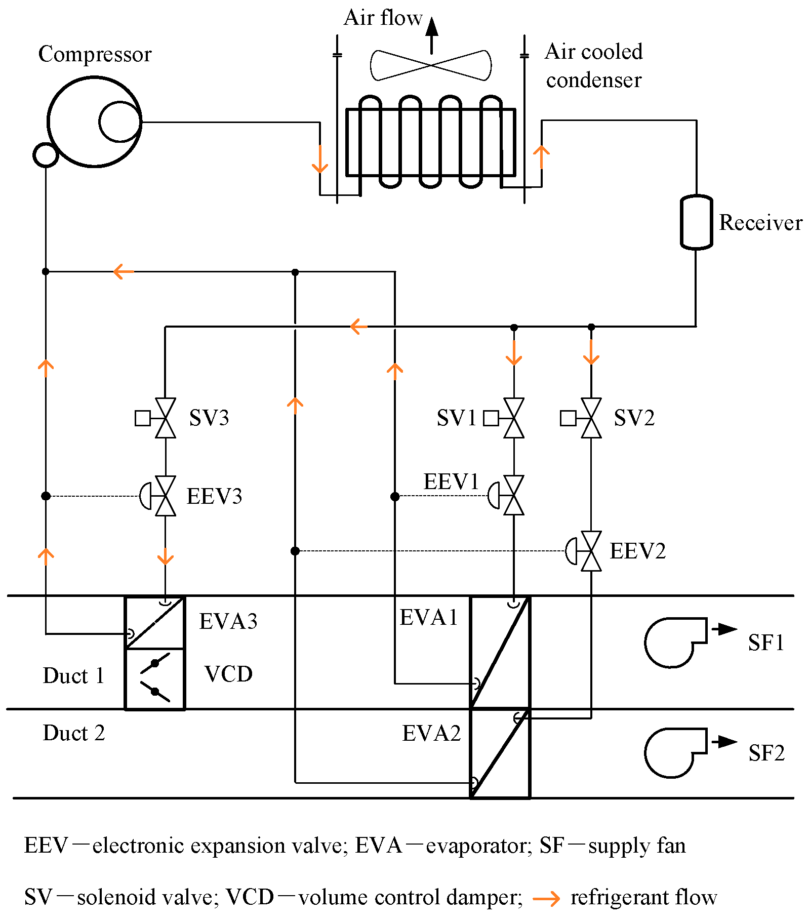
2.1. The Proposed DX-TE System

As illustrated in Figure 1, the DX-TE system comprises a constant-frequency compressor, three strategically positioned evaporators, dual variable-frequency fans, and an air-cooled condenser. The primary distinction of this system from conventional systems lies in its use of multiple evaporators, which must operate in coordination. The system is designed to operate in two fundamental modes, Mode 1 and Mode 2, facilitated by the coordinated interaction of the three evaporators. In Mode 1, evaporators 1 (EVA1) and 2 (EVA2) are configured in parallel, with EVA3 inactive, and both Fan 1 and Fan 2 operational. Conversely, Mode 2 employs a series configuration of EVA1 and EVA3, with EVA2 and Fan 2 inactive. The transition between two modes is governed by the actuation of the system’s incorporated valves. Table 1 provides a comprehensive overview of the operational state of the system’s key control components under two modes.
Within the framework of this system, EVA1, possessing a larger surface area than EVA2 and EVA3, assumes a pivotal role in the processes of cooling and dehumidification. EVA2 or EVA3 supplements these processes by providing additional cooling and dehumidification capacities as necessitated. The system is engineered to operate in two primary modes, both of which allow for the adjustment of the refrigerant flow rate (RR) through the two evaporators by modulating the opening of EEV1 and correspondingly, EEV2 or EEV3, to maintain a steady superheat at the compressor inlet. Furthermore, the airflow rate (AR) passing through the two evaporators can be individually regulated in both modes. In Mode 1, this is achieved by modulating the rotational speed of the two fans, thereby maintaining a constant total air volume and adjusting the proportion of air volume passing through the evaporator. In Mode 2, the proportion of AR passing through the two evaporators can be regulated by modulating the opening of the valve. For the DX-TE system, under both operating modes, any changes in the RR or AR passing through the two evaporators will result in corresponding changes in the evaporation temperature of the two evaporators. Consequently, each evaporator can output varying cooling and dehumidification capacities. Notably, in contrast to conventional DX AC systems, this system is capable of maintaining a constant air volume during operation. Therefore, even if the surface temperature of a particular evaporator drops excessively, resulting in a low-supply air temperature, the overall constant air volume can still maintain the total-supply air temperature at a relatively moderate level, thereby ensuring thermal comfort and optimal air distribution.

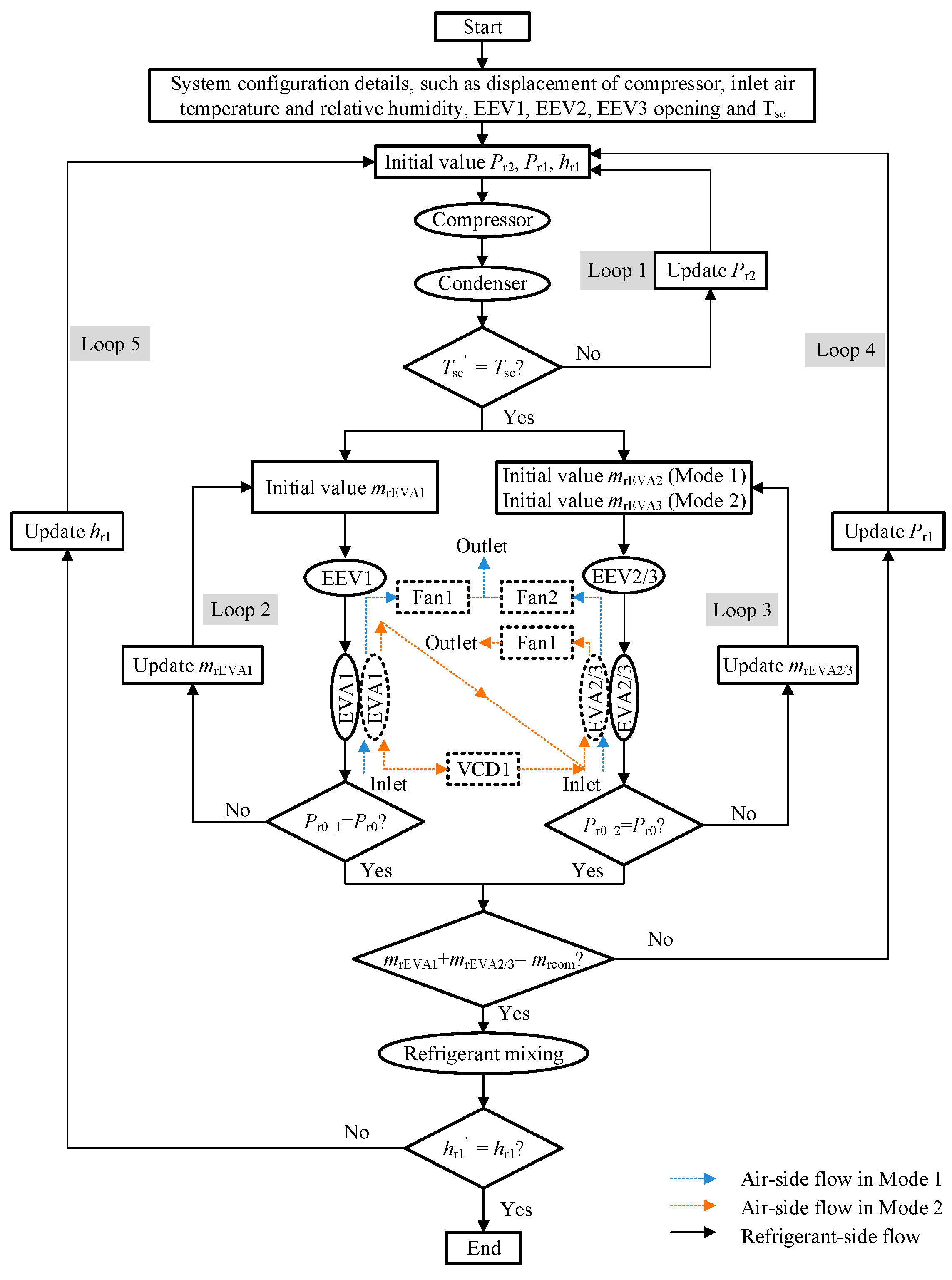
2.2. Development of the Steady-State Model of the DX-TE System

Drawing on the system diagram depicted in Figure 1, a corresponding conceptual model is formulated, illustrated in Figure 2. The conceptual model illustrates the interconnections and interactions among the system’s components, highlighting the distinct performances of the two operating modes of the DX-TE system on both the refrigerant and air sides. This model is fundamentally an assembly of steady-state sub-models, encompassing components such as the compressor, condenser, evaporator, and expansion valve. These sub-models, bearing resemblance to prior research, have demonstrated their efficacy in the simulation studies of DX AC systems [31]. Consequently, this study will persist in utilizing these sub-models to construct the steady-state mathematical model of the DX-TE system. Additionally, all equations for the sub-models and the comprehensive mathematical model are processed using MATLAB (version number: R2018a) software, and the calculation method mainly adopts the bisection method.
The sub-models, as discernible from Figure 2, can be interconnected via the refrigerant flow direction, enabling the output of one sub-model to function as the input for the subsequent one. For instance, parameters such as RR, enthalpy, and pressure, computed by the compressor model, can be employed as input parameters for the condenser model. The results derived from the condenser model can then furnish data for subsequent sub-model computations, thereby facilitating the completion of the entire model’s calculation.
The model employs Refprof [32] for the computation of refrigerant parameters, while the formulas related to air side and humid air parameters are sourced from the ASHRAE Handbook [33]. Additionally, the model computation incorporates the following assumptions:
  • The system sets degree of refrigerant sub-cooling, Tsc, at 5 °C;
  • The superheat at the compressor suction remains constant at 7 °C;
  • The airflow, post traversal through the two evaporators, is evenly mixed and adiabatic;
  • The heat exchange between the refrigerant and the air follows a crossflow pattern.
The assumptions outlined in this study are derived from the specific structure and operational characteristics of the experimental system under investigation. These assumptions facilitate the description of heat and moisture transfer processes through precise mathematical formulations. When applying this mathematical model to other experimental systems, it is imperative to adjust or modify these assumptions to reflect the actual conditions, thereby ensuring the accuracy of the simulation results.
Figure 3 presents a flow chart delineating the computational steps integral to the complete model. The computational procedure is characterized by five iterative loops. The first loop is dedicated to determining the compressor’s outlet pressure, denoted as Pr2. The second and third loops focus on quantifying the RR in various evaporators, under two distinct operational modes. The final two loops, loops 4 and 5, are employed to ascertain the pressure (Pr1) and enthalpy (hr1) of refrigerant at compressor inlet.
Upon specification of the compressor’s Pr1, hr1, and the outlet refrigerant pressure (Pr2), the state of the outlet refrigerant can be ascertained via the compressor model. Subsequently, these parameters are utilized as inputs to the condenser model, facilitating the determination of the Tsc. The convergence of the Tsc dictates the necessity for further iterations of Pr2. Upon completion of this loop, the state of the refrigerant at the condenser’s outlet is obtained, paving the way for the computations in loops 2 and 3. Prior to initiating these calculations, an assumption regarding the refrigerant mass flow entering the expansion valve (mrEVA1, mrEVA2, or mrEVA3) is made. The expansion valve and evaporator model then enable the calculation of the outlet pressure of the refrigerant across two evaporator branches. Given that these parallel branches converge before connecting to the compressor’s suction, the pressure (Pr0) at this juncture can be computed using the compressor’s suction pressure.
A comparison of the refrigerant pressure at the outlets of the two evaporator branches (Pr0_1 and Pr0_2) with Pr0 serves as a determinant of the correctness of the refrigerant flow distribution. If the calculated refrigerant pressure at the outlets of the two branches does not equate to Pr0, an adjustment of the refrigerant flow distribution across the two branches is necessitated, based on the actual calculation results, until convergence is achieved. Concurrently, the air-side calculation of the evaporator sub-model yields the evaporator’s cooling and dehumidification capacities. Following the conclusion of loops 2 and 3, the refrigerants from the two evaporator branches are amalgamated. At this stage, the refrigerant mass flow rate of the system (mrcom), as calculated in loop 1, serves as the convergence criterion for loop 4. If the sum of the refrigerant mass flow rates across the two branches (mrEVA1 and mrEVA2/3) deviates from the result of loop 1, an adjustment of Pr1 is warranted, followed by a recalculation until convergence is reached. Finally, the loop 5 is employed to ascertain whether the initially assumed enthalpy value (hr1) aligns with the calculated enthalpy value (hr1′) following the mixture of the branches. In the event of a discrepancy, the assumed value is adjusted until the results converge, marking the completion of the entire model’s computation.

3. Experimental System and the Validation of the Model

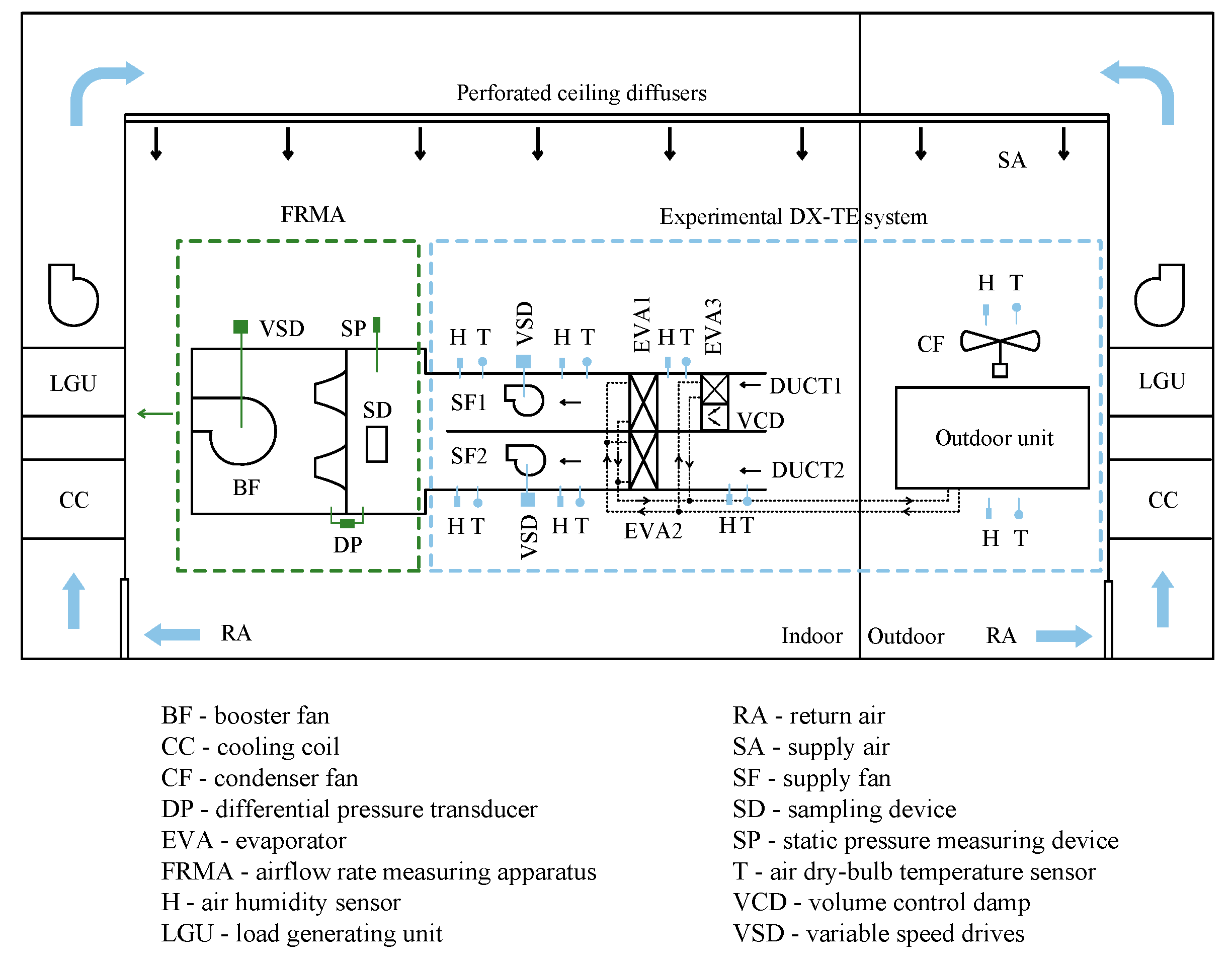
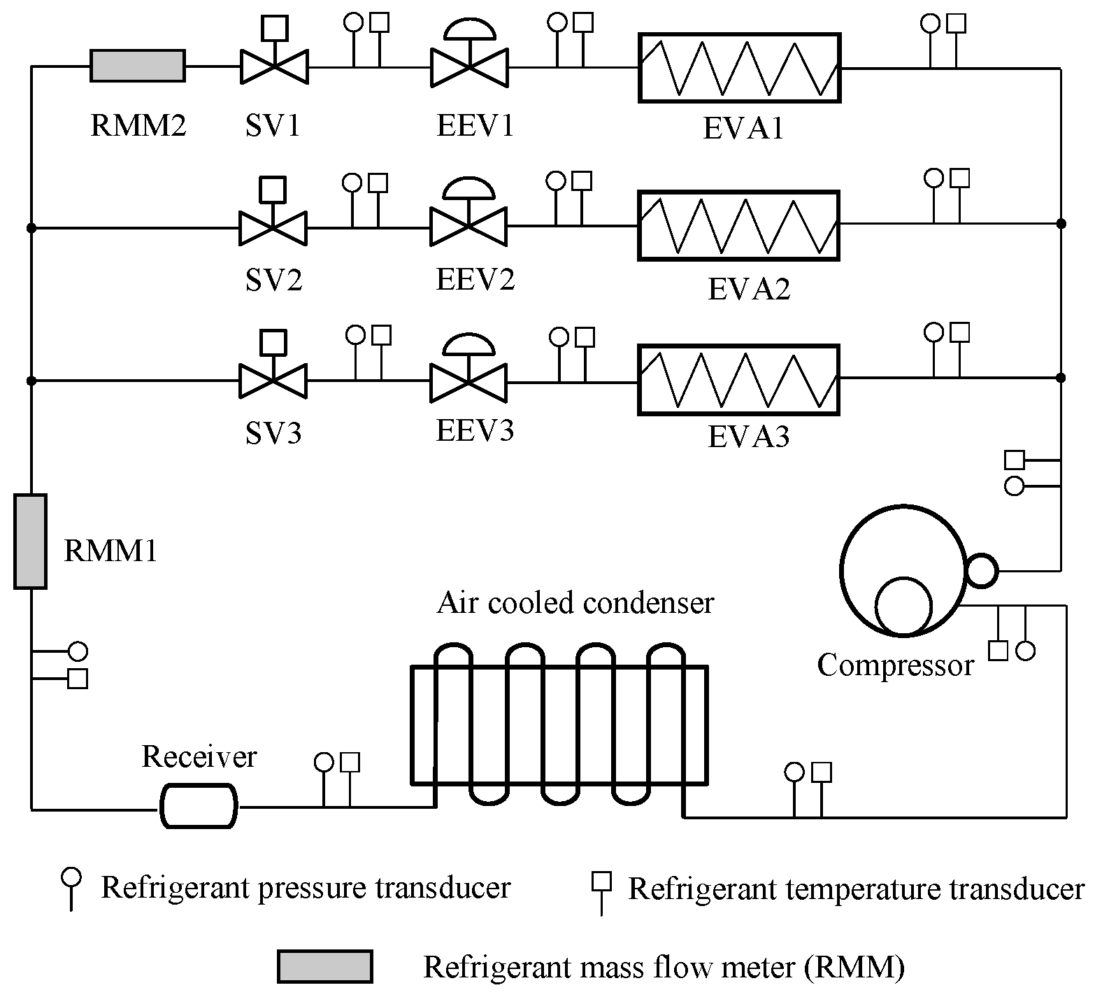
3.1. The Experimental DX-TE System

To validate the mathematical model delineated in Section 2, an experimental platform, as depicted in Figure 4 and constructed in accordance with Figure 1, was instituted. This platform comprises two environmental laboratories, each equipped with an independent air conditioning system, including a cooling coil and a load-generating unit (LGU). Two microprocessor-based PID controllers were employed to establish and sustain the desired experimental conditions within each chamber. Figure 5 illustrates the refrigerant side of this experimental system, primarily composed of a fixed-frequency compressor, an air-cooled condenser, three evaporators, and their corresponding electronic expansion valves (EEVs). The windward dimensions of the three evaporators are as follows: EVA1 measures 450 × 300 mm, EVA2 is 450 × 200 mm, and EVA3 is 450 × 200 mm. The compressor boasts a nominal cooling capacity of 5 kW and employs R410A as the refrigerant. Figure 4 reveals that the air side of this experimental DX-TE system predominantly comprises two independent air supply ducts, corresponding variable frequency fans and air valves, along with an airflow testing apparatus. With the exception of the condenser, the remainder of the experimental system is situated indoors.
Within the confines of this experimental platform, all control elements, encompassing EEVs, fans, and air valves, are interfaced with a centralized control hub, facilitating both manual and automated regulation. The experimental procedure involved the measurement of pertinent operational parameters of both air and refrigerant, with Figure 4 and Figure 5 illustrating the configuration of the corresponding measurement points. A real-time monitoring and recording system is in place for all test parameters.

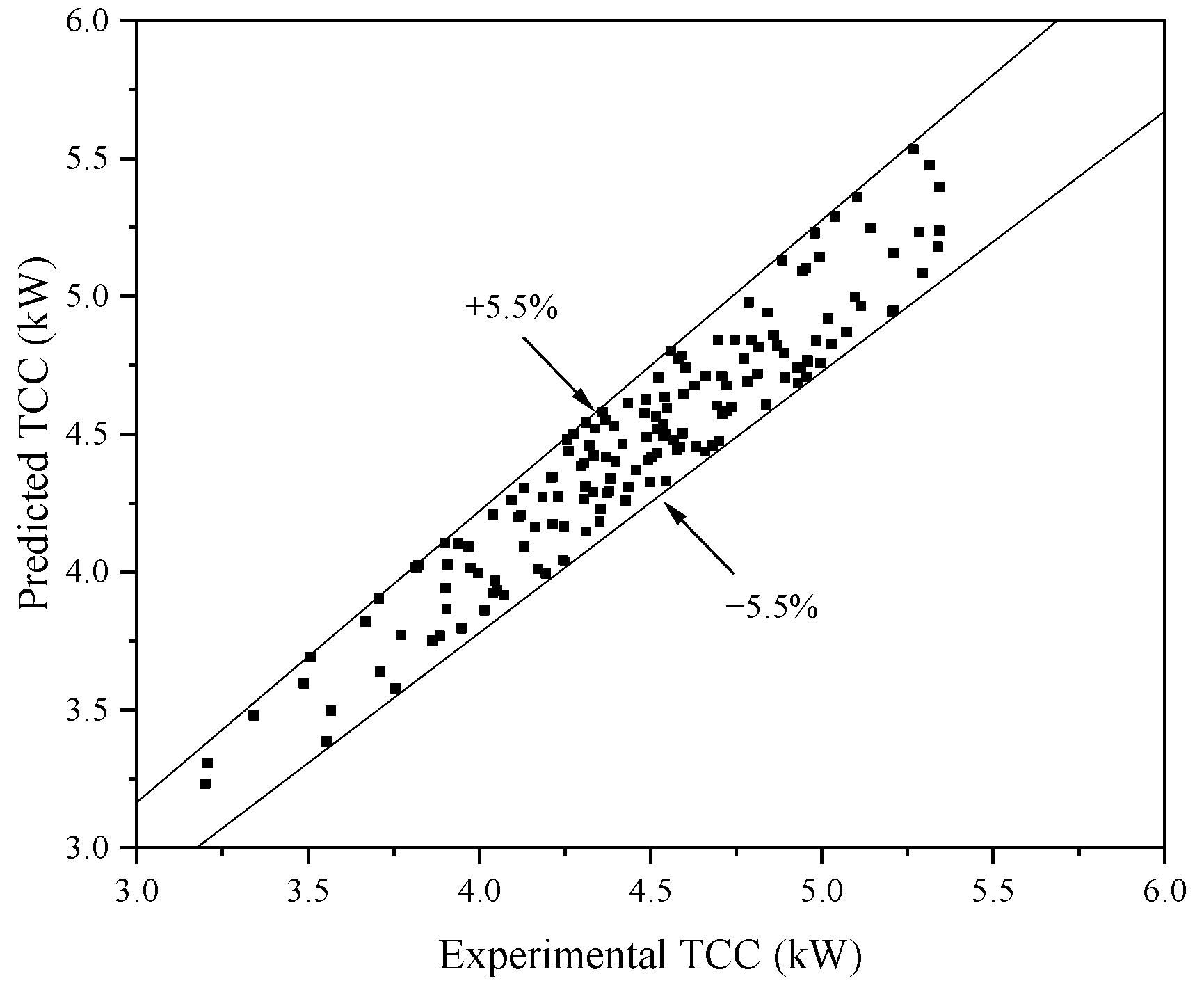
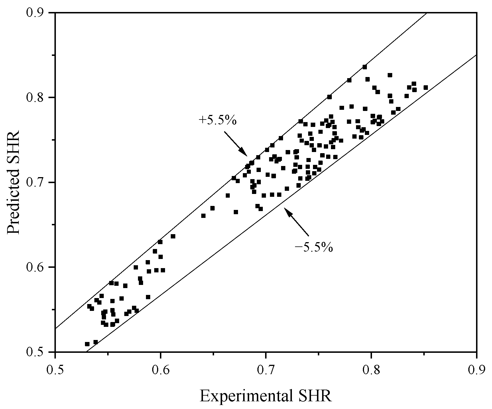
3.2. Model Validation

In the context of this investigation, the parameters’ total cooling capacity (TCC) and sensible heat ratio (SHR) continue to serve as indicators of the comprehensive cooling and dehumidification performance of the DX-TE system. These parameters are employed to ascertain the precision of the model. The definitions of these parameters are provided subsequently:
T C C = m ˙ a × ( h a , i h a , o )
S H R = c × m ˙ a × ( t a , i t a , o ) m ˙ a × ( h a , i h a , o )
where c is the specific heat of air; a is the mass flow rate of air through the evaporator; ta,i and ta,o are the dry bulb temperatures of the air entering and leaving the evaporator; and ha,i, ha,o are the enthalpy values of the air entering and leaving the evaporator.
This system is primarily governed by two key variables. Specifically, under Mode 1, the ratio of RR into EVA2 to the total RR is denoted as Rr, and the ratio of AR into EVA2 to the total AR is represented as Ar. Conversely, under Mode 2, the ratio of RR passing through EVA3 to the total RR is defined as Rr′, and the ratio of AR through EVA3 to the total AR is defined as Ar′. In the course of this experimental investigation, an array of combinations of distinct values of Rr/Rr′ and Ar/Ar′ are employed for experimentation, as delineated in Table 2. The parameters Rr or Rr′ can be modulated by adjusting the opening of EEV1, while concurrently fine-tuning the opening of EEV2 or EEV3 to maintain the superheat of the refrigerant at the compressor suction. The parameter Ar can be manipulated by varying the rotational speed of the two fans, with the speed of one fan being adjusted in tandem with the other to ensure a constant total air volume. The parameter Ar′ can be adjusted by modulating the opening of the air valve while preserving a constant total air volume.
Given the substantial influence of varying air inlet states on the operational characteristics of the system, this investigation initially undertook experimental and simulation studies on the system’s operational outcomes with an inlet air state of 26 °C and 50% relative humidity. The experiment was operated under diverse combinations of Ar/Ar′ and Rr/Rr′, as delineated in Table 2, encompassing a total of 40 experimental scenarios. Throughout the experiment, it was imperative to sustain a steady operational state.
Figure 6 offers a comparative analysis of the experimental and simulated outcomes, with TCC and SHR serving as the horizontal and vertical coordinates, respectively. The experimental and simulated results manifest as two analogous quadrilaterals, designated as ABCD (experimental) and A’B’C’D’ (simulated), signifying the mutual constraint between TCC and SHR. In these irregular quadrilaterals, points A and B, as well as A’ and B’, depict the experimental and simulated outcomes when the system operates in Mode 1, with Rr maintained at 15%, and Ar at 60% and 30%, respectively. Similarly, points C and E represent the experimental and simulated outcomes when Rr is held constant at 50%, and Ar at 60% and 30%, respectively. Under Mode 2 operation, points A and B illustrate the experimental and simulated outcomes when Ar′ is held constant at 30%, and Rr′ varies between 15% and 65%. Points C and D represent the experimental and simulated outcomes when Ar′ is held constant at 60%, and Rr′ varies between 15% and 65%. Both the experimental and simulated data further corroborate that by modulating the values of Rr/Rr′ or Ar/Ar′, the system can achieve variable TCC and SHR values, thereby effectively responding to fluctuating indoor cooling loads.
As discernible from Figure 6, the experimental and simulation results exhibit consistency. Figure 6a illustrates that under Mode 1 operation, with Ar held constant and Rr escalating from 15% to 65%, both the experimental and simulated TCC values initially rise before descending, peaking near 50%. Concurrently, the SHR values initially diminish before augmenting, reaching a lowest point near 50%. It should be noted that curve FG is positioned to the left of borderline CDE. Increasing Rr from 55% to 65% does not expand the irregular area but instead duplicates existing TCC/SHR relationships within ABCDE. At an Rr of 55%, the functions of the two evaporators reverse based on their surface area ratio. EVA2, initially a supplementary section for additional cooling and dehumidification, becomes the primary section as Rr exceeds 55%, with more refrigerant flowing into it. Consequently, EVA1 assumes a supplementary role. Thus, further increasing Rr beyond 55% shifts the TCC/SHR relationship curves leftward within ABCDE.
In a similar situation, as shown in Figure 6b, under Mode 2 operation, with Ar held constant and Rr escalating from 15% to 65%, the experimental and simulated TCC values follow a similar pattern of initial increase followed by a decrease. Moreover, under Mode 1 operation, with Rr held constant and Ar escalating from 30% to 60%, when Ar is less than 40%, the experimental and simulated TCC values consistently decrease, while SHR consistently increases. When Ar exceeds 40%, the experimental and simulated TCC values initially rise before descending, while the SHR values consistently increase. Under Mode 2 operation, with Rr held constant and Ar escalating from 30% to 60%, both the simulated and experimental TCC and SHR values consistently increase.
As evident from Figure 6, under Mode 1, the maximum divergence between the experimental and simulated TCC values across all combinations of Ar and Rr is 2.6%, while the maximum divergence for SHR is 2.1%. Under Mode 2, for all combinations of Ar′ and Rr′, the maximum divergence in the experimental and simulated TCC values is 3.2%, and the maximum divergence in SHR is 2.4%. To further validate the precision of the model, the system advanced to simulate the TCC and SHR results of the two operational modes under four additional distinct inlet air states (26 °C—40%, 22 °C—50%, 24 °C—50%, 28 °C—60%), and these were compared with the experimental results. The comparative results of the experimental and simulated TCC values are portrayed in Figure 7, while the comparative chart of the experimental and simulated SHR values is depicted in Figure 8. From these comparative results, it is clear that the discrepancies between the experimental and simulated data for both sets are contained within ±5.5%, thereby affirming the high accuracy of this steady-state mathematical model through experimental results. As a result, this model will be further utilized for the optimization study of the system evaporator.

4. Modeling Study

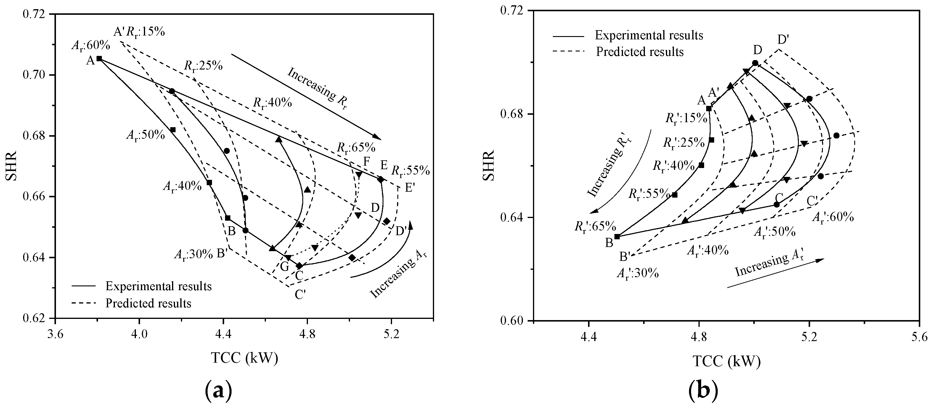
4.1. Variable Cooling Capacities of the DX-TE System

In pursuit of the research objective, it is imperative to authenticate the variable dehumidification capabilities of the proposed DX-TE system. A comparative analysis was conducted on the operational characteristics of this system, the conventional variable speed direct expansion air conditioning (VS-DX) system, and the On-Off controlled DX AC system. Figure 9 delineates the comparative results of the operational characteristics of these systems under an air inlet state of 26 °C and 50% relative humidity. The operational characteristics of the VS-DX system are derived from the empirical research findings of Xia et al. [34]. The VS-DX system allows for adjustable compressor and fan speeds. This adjustability facilitates the system’s variable output capability. The operational characteristics of the DX-TE system, as depicted in the figure, are the outcomes of simulation. The full-load condition of the On-Off controlled DX AC system was also evaluated through simulation. However, part-load conditions, where the compressor cycles off while the supply fan remains running, were assessed using an existing cyclic model [35]. To ensure the credibility of the comparison, the total area of the evaporator in each mode of the DX-TE system under simulated conditions is equivalent to that of a single evaporator in both the VS-DX system and the On-Off controlled DX AC system, maintaining an area ratio of 1:2 between the small and large evaporators.
As depicted in Figure 9, the operational characteristics of the DX-TE system, under a fixed compressor speed and varying combinations of RR and AR ratios, are represented by ABCD (Mode 1) and A’B’C’D’ (Mode 2). The compressor’s fixed speed aligns with the maximum variable speed of the VS-DX system. Concurrently, the output results of the conventional VS-DX system and the On-Off DX AC system are denoted by 1234 and line OC, respectively. An initial examination of the results reveals that the output of the DX-TE system in both modes mirrors that of the VS-DX system, forming a quadrilateral area. For the On-Off controlled A/C system, a decrease in required TCC at part-load conditions significantly increased its output SHR or deteriorated its dehumidification ability. For instance, when the TCC is 7.5, corresponding to Mode 2 of this system, the range of SHR values spans from 0.65 to 0.71. Conversely, in Mode 1 operation, with a TCC of 7.1, the SHR values range from 0.67 to 0.72, significantly lower than the 0.75 observed in On-Off controlled AC systems. This indicates a 24.2% increase in latent cooling capacity, demonstrating the system’s enhanced dehumidification capability.
It merits attention that the dehumidification capacity of the VS-DX system escalates as the fan speed diminishes, as illustrated by the trajectory from point 4 to 3 in the figure. However, this progression is accompanied by a reduction in the TCC. For instance, at point 3, where the SHR is at its lowest value, the system exhibits the most potent dehumidification capacity per unit of cooling, yet its TCC is merely 78% of the peak value. As discernible from the figure, during Mode 2 operation, a segment of its operational area is situated in the lower right quadrant of the VS-DX system’s operational area, as indicated in yellow. This region is referred to as the enhanced cooling and dehumidification area. For instance, when Mode 2 is at points B’ and C’, its TCC and SHR values are 7.08/7.96 and 0.64/0.66, respectively. Corresponding to an equivalent cooling capacity, the operational state points of the VS-DX system are 5 and 6 in the figure, and the SHR values of these two state points are 0.65 and 0.687, respectively. This suggests that under identical cooling capacity, Mode 2 operation exhibits superior dehumidification capacity compared to the VS-DX system.

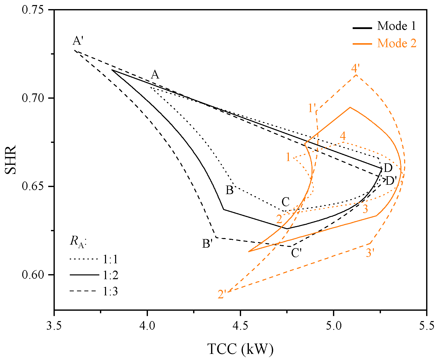
4.2. Optimization of Evaporator Size in the DX-TE System

The DX-TE system, as proposed in this study, maintains a constant windward area for the evaporator within its experimental framework, with the area ratios of evaporators 2 and 3 to 1 consistently at 1:1.5. It is noteworthy that varying area ratios significantly influence the operational characteristics of this system. However, experimental investigation into the effects of changing area ratios presents considerable challenges. Consequently, to delve deeper into the operational characteristics under disparate area ratios, this study employs a pre-established mathematical model. The formula for the area ratio is as follows:
R A = A e v a 2 A e v a 1 = A e v a 3 A e v a 1
where RA is the area ratio of two evaporators; Aeva1 is the surface area of EVA1; Aeva2 is the surface area of EVA2; and Aeva3 is the surface area of EVA3.
The study incorporates RA values of 1:1, 1:2, and 1:3. Primarily, as shown in Figure 10, it is evident that the operational outcomes of the two modes undergo substantial alterations under varying area ratios. As the RA diminishes, the span of both TCC and SHR escalates. For instance, when RA is 1:1, the maximum and minimum of TCC in Mode 1 are 5.27 kW and 4.02 kW, respectively, while that of SHR are 0.706 and 0.636, respectively. In contrast, when RA is 1:3, the peak and trough values of TCC are 5.28 kW and 3.61 kW, respectively, and the maximum and minimum values of SHR are 0.727 and 0.616, respectively. Consequently, the span of TCC amplifies from 1.25 kW to 1.67 kW, marking an increase of 33.6%; the range of SHR augments from 0.07 to 0.111, indicating an increase of 58.6%. Analogously, the span of TCC in Mode 2 elevates from 0.84 to 0.96, signifying an increase of 14.3%, and the range of SHR expands from 0.081 to 0.123, denoting an increase of 51.9%.
Furthermore, it is discernible that under varying area ratios, alterations in Rr and Ar exert differential impacts on the operational characteristics of the system. In Mode 1, as the area disparity between the two amplifies, it is observable that the gradient of curve BC is less steep than that of B’C’. This implies that under conditions of low Ar, the influence of Rr fluctuations on TCC diminishes, while the impact on SHR intensifies. The gradient of curve CD surpasses that of C’D’, indicating that under conditions of high Rr, the influence of Ar alterations on TCC escalates, but the impact on SHR attenuates. Correspondingly, in Mode 2, as the area disparity of the evaporator enlarges, or in other words, when the value of RA contracts, it is evident that the gradient of curve 1′4′ exceeds that of curve 14. This suggests that under conditions of low Rr, the influence of Ar alterations on TCC diminishes, while the impact on SHR intensifies. The curvature of curves 12 and 34 is more pronounced than that of 1′2′ and 3′4′, indicating that as the area ratio expands, under identical Ar, the influence of Rr alterations on TCC escalates, but the impact on SHR attenuates.
Furthermore, it is discernible that the influence of RA alterations diverges between the two modes. In Mode 1, RA modifications exert a more pronounced impact on TCC fluctuations, whereas in Mode 2, these modifications have a more substantial effect on SHR changes. Irrespective of the mode, if a broader range of SHR and TCC alterations is sought, it necessitates a reduction in the RA value. However, certain considerations warrant attention. When a diminished RA value is employed, despite achieving a broader range of TCC and SHR, the minimum TCC value contracts and the maximum SHR value expands concurrently. If an excessively large Rr value is utilized, one of the evaporators fails to effectuate efficient heat exchange, and the other evaporator induces excessive superheat, cumulatively compromising the system’s performance.

4.3. Discussions

The novel DX-TE system proposed in this study incorporates three evaporators, which work in pairs to enable two distinct operating modes. While this system appears slightly more complex than traditional single-evaporator systems, it remains relatively streamlined compared to other temperature and humidity control systems that require additional equipment. This makes it suitable for small to medium-sized buildings with limited installation space. Additionally, the system employs a fixed-speed compressor, resulting in lower initial investment costs and simplified maintenance compared to variable-speed systems. The control strategy is also expected to be more straightforward, as it does not need to account for compressor operation.
The DX-TE system not only improves indoor thermal environmental control but also enhances operational energy efficiency compared to conventional DX A/C systems. This improvement is due to two factors: first, the indoor air-dry bulb temperature can be set higher due to better humidity control, reducing the sensible cooling load. Second, the system can operate with a higher evaporating temperature and thus higher efficiency when EVA2 or EVA3 is not in use, as they are only activated under high latent load conditions.
This study demonstrates that the proposed DX-TE system can output variable cooling and dehumidification capacities under constant compressor speed and airflow, addressing varying indoor sensible and latent heat loads. However, further research is needed to explore practical indoor temperature and humidity control. Specifically, it is necessary to investigate which operating mode should be adopted under different indoor load conditions and how to adjust the RR and AR of the evaporators to enhance system efficiency. Additionally, it is important to note that when the system operates at a low SHR, the superheat of one evaporator may abnormally decrease, thereby affecting overall system efficiency. This requires careful attention during specific control operations. These aspects will be addressed in subsequent research.

5. Conclusions

In an endeavor to enhance the regulation and control of temperature and humidity in DX AC systems for small to medium-sized buildings, and to circumvent the need for additional equipment or minimize the impact on the indoor thermal environment, this study introduces a novel DX AC system equipped with three evaporators (DX-TE). This system, featuring a constant speed compressor and three evaporators operating in tandem, primarily operates in two modes. In both modes, adjustments to the refrigerant flow and air volume of each evaporator enable the achievement of variable cooling output. This research employs both experimental and simulation methodologies to investigate the operational characteristics and system optimization structure of this system. The principal conclusions drawn are as follows:
(1)
This system can deliver variable cooling capacity in two operating modes while maintaining a constant compressor speed and air supply volume, thereby adapting to the fluctuating cooling load in the room and facilitating temperature and humidity control;
(2)
The study formulated a steady-state mathematical model of the system and validated the model under diverse operating conditions. The findings indicate that the maximum discrepancies in TCC and SHR are confined within ±5.5%;
(3)
In comparison with the conventional variable frequency direct expansion system of identical specification, this system exhibits enhanced dehumidification capability, which can be augmented by up to 9.7%;
(4)
In the two operating modes, the area ratio between the evaporators exerts a significant influence on the operational characteristics of the system. As the area ratio transitions from 1:1 to 1:3, the range of TCC expands by 33.6% and 14.3%, respectively, and the operational range of SHR expands by 58.6% and 51.69%.

Author Contributions

L.Y.: writing—original draft, conceptualization, methodology, investigation. X.Z.: data curation, conceptualization, validation. H.W.: supervision, formal analysis. W.B.: writing—review and editing. S.L.: validation. All authors have read and agreed to the published version of the manuscript.

Funding

This research was funded by the Department of Science and Technology of Henan Province, China, grant number No. 222103810076 and No. 232102111126.

Data Availability Statement

The data presented in this study are available on request from the corresponding author.

Conflicts of Interest

The authors declare no conflicts of interest.

References

  1. Yang, Z.; Gao, W.; Yang, D.; Hu, X.; Xu, T. Impact of Air Velocity on Mold Growth in High Temperature and Humidity Conditions: An Experimental Approach. Buildings 2024, 14, 2145. [Google Scholar] [CrossRef]
  2. Cui, W.; Cao, G.; Park, J.H.; Ouyang, Q.; Zhu, Y. Influence of indoor air temperature on human thermal comfort, motivation and performance. Build. Environ. 2013, 68, 114–122. [Google Scholar] [CrossRef]
  3. Sirror, H.; Labib, W.; Abowardah, E.; Metwally, W.; Mitchell, C. Sustainability in the Workplace: Evaluating Indoor Environmental Quality of a Higher Education Building in Riyadh. Buildings 2024, 14, 2115. [Google Scholar] [CrossRef]
  4. Su, X.; Geng, Y.; Huang, L.; Li, S.; Wang, Q.; Xu, Z.; Tian, S. Review on dehumidification technology in low and extremely low humidity industrial environments. Energy 2024, 302, 131793. [Google Scholar] [CrossRef]
  5. Yang, K.; Chu, F.; Li, J.; Wang, Y.; Dong, X.; Liu, J.; Mao, Y. Study on the Modified Ventilation Network on the Ventilation Effect and Ozone Migration Characteristics in Grain Pile. Buildings 2024, 14, 604. [Google Scholar] [CrossRef]
  6. Zhao, X.; Yin, Y.; He, Z.; Deng, Z. State-of-the-art, challenges and new perspectives of thermal comfort demand law for on-demand intelligent control of heating, ventilation, and air conditioning systems. Energy Build. 2023, 295, 113325. [Google Scholar] [CrossRef]
  7. Lin, Y.-H.; Lin, M.-D.; Tsai, K.-T.; Deng, M.-J.; Ishii, H. Multi-objective optimization design of green building envelopes and air conditioning systems for energy conservation and CO2 emission reduction. Sustain. Cities Soc. 2021, 64, 102555. [Google Scholar] [CrossRef]
  8. Xu, X.; Zhong, Z.; Deng, S.; Zhang, X. A review on temperature and humidity control methods focusing on air-conditioning equipment and control algorithms applied in small-to-medium-sized buildings. Energy Build. 2018, 162, 163–176. [Google Scholar] [CrossRef]
  9. Yao, Y.; Shekhar, D.K. State of the art review on model predictive control (MPC) in Heating Ventilation and Air-conditioning (HVAC) field. Build. Environ. 2021, 200, 107952. [Google Scholar] [CrossRef]
  10. Ling, J.; Hwang, Y.; Radermacher, R. Theoretical study on separate sensible and latent cooling air-conditioning system. Int. J. Refrig. 2010, 33, 510–520. [Google Scholar] [CrossRef]
  11. Ling, J.; Kuwabara, O.; Hwang, Y.; Radermacher, R. Experimental evaluation and performance enhancement prediction of desiccant assisted separate sensible and latent cooling air-conditioning system. Int. J. Refrig. 2011, 34, 946–957. [Google Scholar] [CrossRef]
  12. Han, X.; Zhang, X.; Wang, L.; Niu, R. A novel system of the isothermal dehumidification in a room air-conditioner. Energy Build. 2013, 57, 14–19. [Google Scholar] [CrossRef]
  13. Fan, H.; Shao, S.; Tian, C. Performance investigation on a multi-unit heat pump for simultaneous temperature and humidity control. Appl. Energy 2014, 113, 883–890. [Google Scholar] [CrossRef]
  14. Rudd, A. BA-1310: Supplemental Dehumidification in Warm-Humid Climates; Building America Report; Building Science Corporation: Somerville, MA, USA, 2013. [Google Scholar]
  15. Mazzei, P.; Minichiello, F.; Palma, D. HVAC dehumidification systems for thermal comfort: A critical review. Appl. Therm. Eng. 2005, 25, 677–707. [Google Scholar] [CrossRef]
  16. Jeong, J.; Yamaguchi, S.; Saito, K.; Kawai, S. Performance analysis of four-partition desiccant wheel and hybrid dehumidification air-conditioning system. Int. J. Refrig. 2010, 33, 496–509. [Google Scholar] [CrossRef]
  17. Martínez, P.J.; Llorca, C.; Pla, J.A.; Martínez, P. Experimental validation of the simulation model of a DOAS equipped with a desiccant wheel and a vapor compression refrigeration system. Energies 2017, 10, 1330. [Google Scholar] [CrossRef]
  18. Zhang, Z.; Cao, X.; Yang, Z.; Shao, L.; Zhang, C. Modeling and experimental investigation of an advanced direct-expansion outdoor air dehumidification system. Appl. Energy 2019, 242, 1600–1612. [Google Scholar] [CrossRef]
  19. Li, Z.; Chen, J.; Yu, H.; Cui, L. The development and experimental performance evaluation on a novel household variable refrigerant flow based temperature humidity independently controlled radiant air conditioning system. Appl. Therm. Eng. 2017, 122, 245–252. [Google Scholar]
  20. Shao, S.; Shi, W.; Li, X.; Chen, H. Performance representation of variable-speed compressor for inverter air conditioners based on experimental data. Int. J. Refrig. 2004, 27, 805–815. [Google Scholar] [CrossRef]
  21. Shiming, D. A dynamic mathematical model of a direct expansion (DX) water-cooled air-conditioning plant. Build. Environ. 2000, 35, 603–613. [Google Scholar] [CrossRef]
  22. Li, Z.; Deng, S. An experimental study on the inherent operational characteristics of a direct expansion (DX) air conditioning (A/C) unit. Build. Environ. 2007, 42, 1–10. [Google Scholar] [CrossRef]
  23. Xu, X.; Xia, L.; Chan, M.; Deng, S. Inherent correlation between the total output cooling capacity and equipment sensible heat ratio of a direct expansion air conditioning system under variable-speed operation (XXG SMD SHR DX AC unit). Appl. Therm. Eng. 2010, 30, 1601–1607. [Google Scholar] [CrossRef]
  24. Li, Z.; Deng, S.A. DDC-based capacity controller of a direct expansion (DX) air conditioning (A/C) unit for simultaneous indoor air temperature and humidity control–Part I: Control algorithms and preliminary controllability tests. Int. J. Refrig. 2007, 30, 113–123. [Google Scholar] [CrossRef]
  25. Xu, X.; Deng, S.; Chan, M. A new control algorithm for direct expansion air conditioning systems for improved indoor humidity control and energy efficiency. Energy Convers. Manag. 2008, 49, 578–586. [Google Scholar] [CrossRef]
  26. Yan, H.; Deng, S.; Chan, M. A novel capacity controller for a three-evaporator air conditioning (TEAC) system for improved indoor humidity control. Appl. Therm. Eng. 2016, 98, 1251–1262. [Google Scholar] [CrossRef]
  27. Li, N.; Xia, L.; Deng, S.; Xu, X.; Chan, M. Dynamic modeling and control of a direct expansion air conditioning system using artificial neural network. Appl. Energy 2012, 91, 290–300. [Google Scholar] [CrossRef]
  28. Yan, H.; Xia, Y.; Xu, X.; Deng, S. Inherent operational characteristics aided fuzzy logic controller for a variable speed direct expansion air conditioning system for simultaneous indoor air temperature and humidity control. Energy Build. 2018, 158, 558–568. [Google Scholar] [CrossRef]
  29. Li, N. Comparison of the characteristics of the control strategies based on artificial neural network and genetic algorithm for air conditioning systems. J. Build. Eng. 2023, 66, 105830. [Google Scholar] [CrossRef]
  30. Zhao, K.; Liu, X.; Zhang, T.; Jiang, Y. Performance of temperature and humidity independent control air-conditioning system in an office building. Energy Build. 2011, 43, 1895–1903. [Google Scholar] [CrossRef]
  31. Pan, Y.; Xu, X.; Xia, L.; Deng, S. A modeling study on the effects of refrigerant pipeline length on the operational performance of a dual-evaporator air conditioning system. Appl. Therm. Eng. 2012, 39, 15–25. [Google Scholar]
  32. Lemmon, E.; Huber, M.; McLinden, M. NIST Standard Reference Database 23: Reference Fluid Thermodynamic and Transport Properties-REFPROP; Version 9.1; National Institute of Standards and Technology: Gaithersburg, MD, USA, 2010.
  33. ASHRAE. ASHRAE Handbook Fundamentals; American Society of Heating, Refrigerating and Air-Conditioning Engineers: Atlanta, GA, USA, 2009. [Google Scholar]
  34. Xia, Y.; Deng, S.; Chan, M. Inherent operational characteristics and operational stability of a variable speed direct expansion air conditioning system. Appl. Therm. Eng. 2017, 113, 268–277. [Google Scholar] [CrossRef]
  35. Shirey, D.B., III; Henderson, H.I., Jr.; Raustad, R.A. Understanding the Dehumidification Performance of Air-Conditioning Equipment at Part-Load Conditions; University of Central Florida: Orlando, FL, USA, 2006. [Google Scholar]
Figure 1. Schematic diagram of the proposed DX-TE system.
Buildings 14 02846 g001
Figure 2. Conceptual model of the proposed DX-TE system.
Buildings 14 02846 g002
Figure 3. Flow chart of the calculation procedure of the complete DX-TE model.
Buildings 14 02846 g003
Figure 4. The experimental system of the proposed DX-TE system.
Buildings 14 02846 g004
Figure 5. Refrigerant side of the proposed DX-TE system.
Buildings 14 02846 g005
Figure 6. (a) Comparison of experimental and simulation results under Mode 1; (b) comparison of experimental and simulation results under Mode 2.
Buildings 14 02846 g006
Figure 7. Comparison of experimental and predicted results of TCC values.
Buildings 14 02846 g007
Figure 8. Comparison of experimental and predicted results of SHR values.
Buildings 14 02846 g008
Figure 9. Comparison of different systems’ operating performance.
Buildings 14 02846 g009
Figure 10. Variations of TCC and SHR values under different RA values.
Buildings 14 02846 g010
Table 1. Statues of control components in the DX-TE system under two modes.
ComponentsOperating Statues
Mode 1Mode 2
SV1OO
SV2OC
SV3CO
SF1OO
SF2OC
VCDOPO
Note: O: open C: close PO: partially open.
Table 2. Values of Ar/Ar′ and Rr/Rr′ used in the experiment.
No.1234/
Ar or Ar′30%40%50%60%/
No.12345
Rr or Rr′15%25%40%55%65%
Disclaimer/Publisher’s Note: The statements, opinions and data contained in all publications are solely those of the individual author(s) and contributor(s) and not of MDPI and/or the editor(s). MDPI and/or the editor(s) disclaim responsibility for any injury to people or property resulting from any ideas, methods, instructions or products referred to in the content.

