Article

Numerical and Theoretical Study on Flexural Performance and Reasonable Structural Parameters of New Steel Grating–UHPFRC Composite Bridge Deck in Negative Moment Zone

1
School of Civil Engineering, Southeast University, Nanjing 211189, China
2
CCCC Second Highway Engineering Co., Ltd., Xi’an 710065, China
3
Research and Development Center on Construction Technology of Long Bridge and Tunnel in Mountain Areas, CCCC, Xi’an 710199, China
4
School of Highway, Chang’an University, Xi’an 710064, China
5
School of Electric Power, Civil Engineering and Architecture, Shanxi University, Taiyuan 030006, China
*
Authors to whom correspondence should be addressed.
Buildings 2024, 14(9), 2857; https://doi.org/10.3390/buildings14092857
Submission received: 23 June 2024 / Revised: 19 August 2024 / Accepted: 5 September 2024 / Published: 10 September 2024
(This article belongs to the Special Issue Optimal Design of FRP Strengthened/Reinforced Construction Materials)

Abstract

:
As the bridge’s structural component is directly subjected to vehicle loads, the stress performance of the bridge deck has a significant impact on the safety, durability, and driving comfort of the bridge. In order to improve the bending performance of the bridge deck in the negative moment zone, a new type of steel grating–UHPFRC composite bridge deck was proposed in this paper. Firstly, structural details and advantages of the new steel grating-UHPFRC composite bridge deck were introduced. Secondly, the finite element program ABAQUS was used to establish a refined solid finite element model of the new bridge deck. The mathematical program MATLAB (PYTHON) was also used to analyze the effects of the structural parameters on bending bearing capacity and put forward reasonable structural parameters of the new bridge deck, considering the technical and economic indexes. Thirdly, the simplified plasticity theory was applied to analyze the bending bearing capacity of the new bridge deck, and the corresponding formula for bending bearing capacity calculation was derived and verified by numerical model results. In addition, the cost–benefit analysis and environmental impact assessment of the new bridge deck were also conducted. The results show that the bending bearing capacity of the new bridge deck in the negative moment zone increases with the increase of the width of the bridge deck, the thickness of the wing plate, and the height of the web plate, with a trend of increasing and then decreasing when the horizontal inclination of the web plate decreases. The bridge deck width does not have a significant effect on improving the bearing capacity. The bearing capacity calculated by theoretical formulas is close to that calculated by numerical models and the maximum relative deviation is 9.1%. The new steel grating-UHPFRC composite bridge deck proposed in this paper is superior to conventional steel-UHPC composite bridge deck in terms of cost-benefit and environmental impact.

1. Introduction

The bridge deck is one of the most vulnerable parts of the whole bridge. Under the action of vehicle load, the bending performance of a conventional bridge deck in the negative bending moment zone cannot meet the increasing demand for traffic loads due to its large self-weight, poor bending performance, and cracking. Therefore, scholars have proposed an orthotropic steel bridge deck in order to effectively solve the problems existing in conventional concrete bridge decks [1,2,3,4].
Lu et al. [5], Sun et al. [6], Tian et al. [7], and Wu et al. [8] analyzed reasonable construction parameters, as well as their influence on the bearing capacity, through numerical simulation and obtained relatively reasonable structural parameters. Regarding research on fatigue performance, Shi et al. [9] conducted a case study on an existing highway viaduct in northern Italy and implemented an automatic “rainflow” algorithm based on finite element simulation, which can detect every nominal stress change exceeding the fatigue limit. In order to improve the fatigue performance of orthotropic steel bridge decks, Xu et al. [10] proposed three new types of longitudinal stiffening ribs. The fatigue life of the longitudinal stiffening ribs and the diaphragm with the “apple hole” opening form was found to be the highest, through 10 million fatigue loading experiments. Aiming at the problem of uneven stiffness distribution in the transverse direction of orthotropic steel bridge decks, which leads to a significant local stress concentration effect, Wu et al. [11] put forward six new orthotropic steel bridge decks with different cross-sections of longitudinal stiffening ribs. The deflection, transverse stress, and other linear and mechanical indexes were analyzed by numerical simulation to determine the reasonable structural parameters. However, in the application of orthotropic steel bridge decks, there are still some outstanding problems, such as complicated construction, easy fatigue cracking, and low stiffness [12,13]. In view of the above problems, researchers have developed a type of composite bridge deck (steel–concrete composite bridge deck), that can increase the stiffness of the bridge deck system, significantly reducing the overall stress level and the risk of fatigue cracking of the bridge deck.
Zafar et al. [14] conducted model tests on six specimens to study the mechanical and crack resistance properties of steel–UHPC composite bridge decks. The experimental results showed that the overall stiffness of the steel–UHPC composite bridge deck structure was higher, and its crack resistance performance was better than that of traditional bridge decks. Luo et al. [15] established refined finite element models of steel–UHPC components with different design parameters, based on ABAQUS, and proposed calculation formulas for the cracking load and bearing capacity of steel-UHPC composite bridge decks. The results showed that the theoretical formula calculation results were in good agreement with the experimental ones, and the proposed formulas had good applicability. Zhang et al. [16] studied the durability and mechanical properties of steel–UHPC composite bridge decks, taking the Wuhan Junshan Yangtze River Bridge as the background. They concluded that the steel–UHPC composite bridge decks have the advantages of strong durability, small creep shrinkage, crack resistance, and high flexural strength, Xiang et al. [17] put forward a closed-rib steel–UHPC composite bridge deck, without additional arc cuts at the connection between longitudinal stiffeners and diaphragm, and showed that this new structure could significantly simplify the manufacturing process of orthotropic steel bridge decks, which means significant economic benefits. Liu et al. [18], Shao et al. [19], and Hu et al. [20] designed and prefabricated three steel–UHPC composite decks with interfaces in different negative moment zones and conducted experimental research, which showed that the application of steel–UHPC composite decks in the negative moment zone could effectively improve the crack resistance of the bridge deck. Abbas et al. [21] studied the material properties of UHPC in the steel–UHPC composite bridge deck, and a prediction model for the shear-bearing capacity of the steel–UHPC interface was established, based on experimental results and relevant literature. It was found that adding high-strength fibers to UHPC can prolong the structural life of the steel–UHPC composite bridge deck. Ding et al. [22] and Gu et al. [23] analyzed the fatigue performance of steel–UHPC lightweight composite bridge decks through model tests and numerical simulation. The results show that the lightweight composite bridge deck improves the fatigue details and stress amplitude of the connection between the steel plate and longitudinal ribs, while the improvement of the rest of the fatigue details is relatively small. However, the following issues still exist in the application process of steel–UHPC composite bridge decks, such as large structural self-weight. The connection performance between steel and concrete is not reliable enough.
Aiming at solving the above problems, Liu et al. [24,25], Sun et al. [26], Zhang et al. [27], and Zhao et al. [28] carried out a reasonable structural parameter analysis for steel–UHPC bridge decks, analyzed the influence of structural parameters on the self-weight and bending bearing capacity through finite element simulation, and proposed reasonable values of structural parameters for the steel-UHPC bridge deck. In order to reduce the self-weight of the steel-UHPC bridge deck, Shao [29,30] and Zhao [31] developed a kind of lightweight steel–UHPC bridge deck and studied the stress performance through a positive moment loading test to verify its feasibility of application in actual projects. Qiu et al. [32] conducted a model beam loading test by using rubber sleeve connectors and ordinary pin shear connectors to clarify the shear performance of the above two types of shear connectors. The comparative analysis of the test results showed that the rubber sleeve connectors can improve the strain distribution of the composite beam in the early loading stage and improve the crack resistance of the steel–UHPC composite bridge deck. Shan et al. [33] and Liu et al. [34] carried out studies on the influence of structural parameters of PBL shear connectors on bearing capacity, and the results showed that the bearing capacity increased accordingly with the increase in the hole spacing of the PBL shear connectors. He et al. [35], Yang et al. [36], and Guo et al. [37] conducted a comparative study on the influence of PBL shear connectors and peg-type shear connectors on the interfacial slip performance of the steel–concrete bridge deck. It was concluded that the PBL shear connectors had superior longitudinal slip resistance compared with peg-type shear connectors and could effectively resist interfacial slip and spalling. However, the above research mainly focuses on the flexural performance of composite bridge decks in the positive bending moment zone, while in the actual project, the force state of composite bridge decks in the negative moment area is more unfavorable, and there are few reports on cost–benefit analysis and environmental impact assessment for composite bridge decks.
In this paper, a new steel grating–UHPFRC composite bridge deck is proposed to solve the above problems existing in current composite bridge decks. Numerical simulation and theoretical research methods are used to study the bending performance and reasonable configuration of the new steel grating–UHPFRC composite bridge deck under the action of negative bending moment, and the theoretical formulas for calculating the bearing capacity and the reasonable structural parameters of each component of the composite bridge deck are also proposed. In addition, the cost–benefit analysis and environmental impact assessment of the new composite bridge deck are also studied.

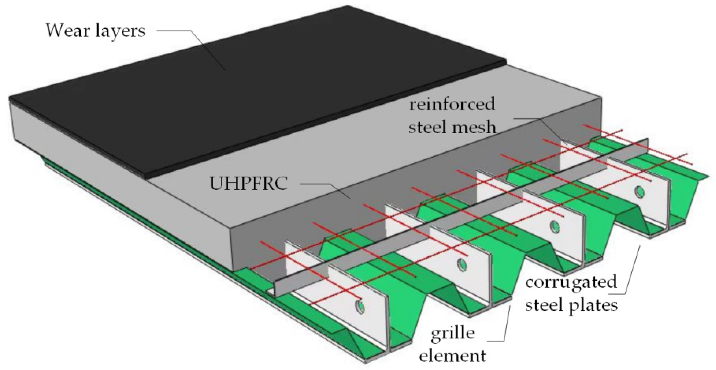
2. Details and Advantages of New Steel Grating–UHPFRC Composite Bridge Deck

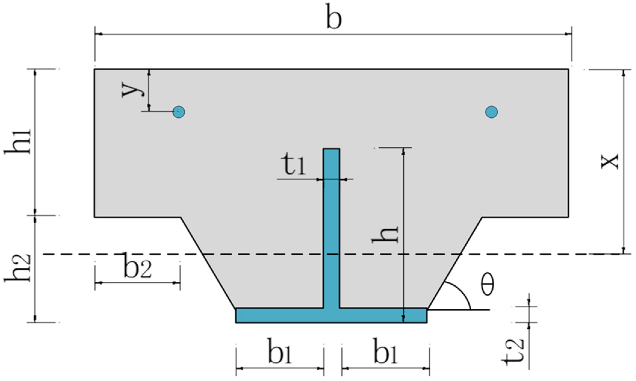
2.1. Details of New Steel Grating–UHPFRC Composite Bridge Deck

The steel grating–UHPFRC composite bridge deck is composed of load-bearing steel grating components, ultra-high performance concrete layers (UHPFRC), corrugated steel plates serving as construction templates, reinforced steel mesh to enhance interface shear resistance, and wear layers laid on concrete, as shown in Figure 1. The steel grating components are formed by welding rolled T-shaped steel and angle steel and are prefabricated in the factory, according to the construction method of conventional steel structures. UHPFRC wraps the corrugated steel web, angle steel, and steel mesh in the steel grating components as a whole. The biggest characteristic of composite structures is to fully utilize the mechanical performance advantages of each component. To ensure that the steel grating–UHPFRC composite bridge deck maximizes the performance of each material, it mainly relies on the effective connection between the steel grating and UHPFRC.

2.2. Advantages of New Steel Grating–UHPFRC Composite Bridge Deck

The steel grating–UHPFRC composite bridge deck has the following characteristics:
  • Under the same section bending stiffness, the composite bridge deck requires less concrete, which helps to reduce the self-weight of the bridge deck and improve the bridge’s crossing capacity;
  • The composite bridge deck is formed as a whole by combining steel grating and UHPFRC, which can fully utilize the mechanical properties of both materials and has a large bearing capacity and bending stiffness;
  • The superior flexural and tensile strength of UHPFRC can greatly improve the problem of concrete cracking in the negative bending moment zone of bridge decks;
  • The corrugated steel plate can serve as a template for concrete pouring, saving the workload of setting up scaffolding and installing and removing templates, which is beneficial for accelerating the construction process and reducing construction costs.

3. Numerical Model

3.1. Material Parameters

The material mix proportions and mechanical performance parameters used in this study are shown in Table 1, Table 2 and Table 3.

3.2. Concrete Constitutive Model

The axial tensile and compression tests were conducted on UHPFRC, and the stress–strain relationship curves of UHPFRC were measured. The curve is consistent with the concrete plastic damage model (CDP) provided by ABAQUS 6.14. Therefore, the CDP model was adopted as the concrete constitutive model. The ontological relationship was adapted from the Code for the Design of Concrete Structures (GB 50010-2010) [38]. The constitutive curve is given in Exhibit C.
The uniaxial tensile stress–strain relationship for concrete is determined by Equation (1).
σ = f t , r 1.2 ε ε t , r 0.2 ε ε t 6 ε ε t σ = f t , r ε ε t , r α t ε ε t , r 1 1.7 + ε ε t ε > ε t
where f t is the uniaxial tensile strength of concrete, ε t is the peak tensile strain of concrete, and α t is the parameter for the descending section of the stress-strain curve.
The uniaxial compressive stress–strain relationship for concrete is determined by Equation (2).
σ = f c α a ε ε c + 3 2 α ε ε c 2 + α a 2 ε ε c 3 ε ε c σ = f c , r ε ε c α d ε ε c 1 2 + ε ε c ε > ε c
where α a and α d are the parameters of the rising and falling sections of the uniaxial compressive stress-strain curve of concrete, f c is the uniaxial compressive strength of concrete, and ε c is the peak compressive strain of concrete.

3.3. Steel Constitutive Model

The equivalent ideal elastic-plastic bilinear model provided in Schedule C of the Code for the Design of Concrete Structures (GB 50010-2010) (2015 version) was used, and the modulus of elasticity during the strengthening phase was taken as 0.02 E. The curves of the concrete constitutive model are shown in Figure 2.

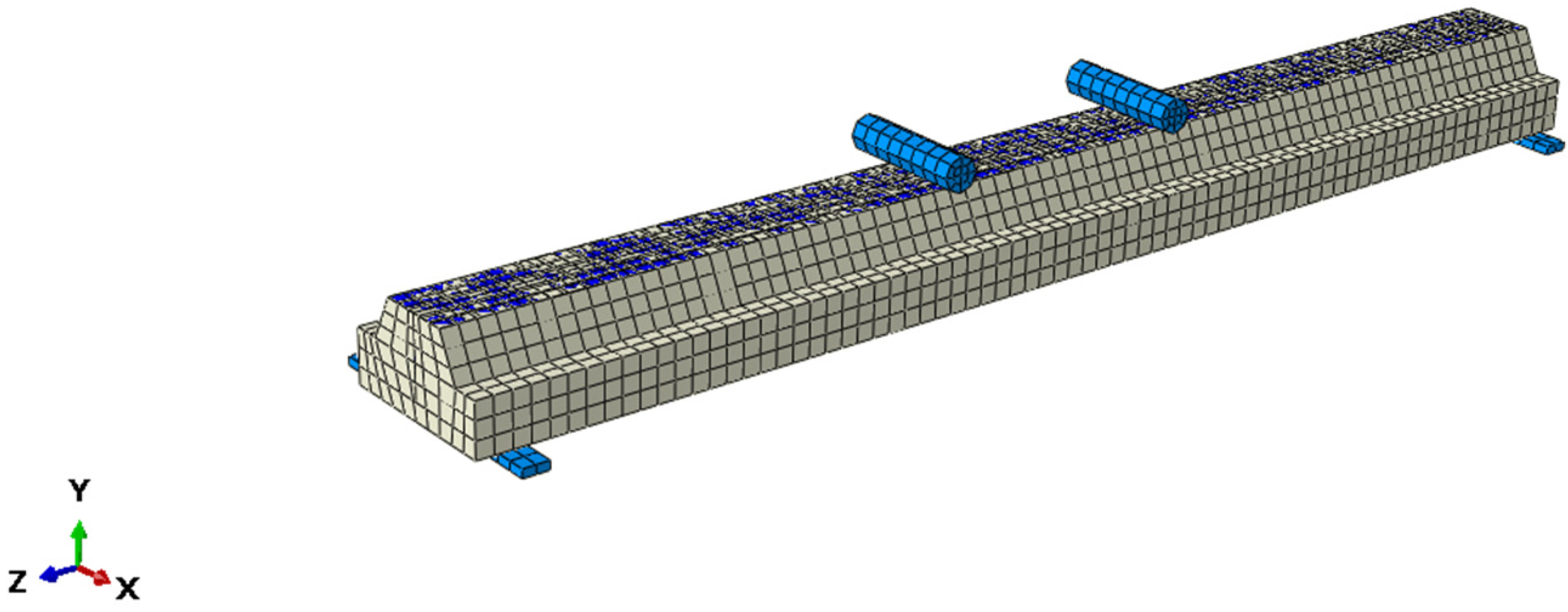
3.4. Cell Selection and Meshing

The finite element program ABAQUS was used to establish the refined finite element model of the new steel grating–UHPFRC composite bridge deck. The longitudinal length of the composite bridge deck was 3 m, which was divided into 4975 elements and 6677 nodes. Three kinds of basic elements were used in the numerical simulations, among which: “丄” steel was simulated by shell element (S4R), concrete and loading pads were simulated by three-dimensional solid element (C3D8R), and rebar was simulated by truss element (T3D2). According to the sensitivity test results of the calculation results, the efficiency based on the previous grid size, and considering both the accuracy of the calculation results and the computation time, the grid division and scale were as follows: for the “丄” steel shell element, in order to prevent the stress concentration caused by the calculation results that do not converge, the grid size was refined to 20 mm and the concrete and loading pad solid element and rebar truss element used 40 mm grid-scale and 30 mm grid scale, respectively. At the same time, the grid was moderately encrypted in the stress concentration area. The finite element model of the new steel grid–UHPFRC composite bridge deck is shown in Figure 3.

3.5. Contact Relationships

The finite element model of the new steel grid–UHPFRC composite bridge deck mainly included the following five types of contact relationships: (1) contact relationship between steel web and concrete; (2) contact relationship between steel flange and concrete; (3) contact relationship between rebar and concrete; (4) contact relationship between loading pad and upper surface of steel; and (5) contact relationship between loading pad and concrete. Based on the conclusions of related research [39] and considering the accuracy and calculation efficiency of the simulation, the contact relationships of the new steel grid–UHPFRC composite bridge deck were set as follows: (1) and (3) were set as built-in embedded contact, and (2), (4), and (5) were set as binding constraints.

3.6. Boundary Conditions

In order to simulate the stress conditions of the new steel grating–UHPFRC composite bridge deck under negative bending moment, a simply supported boundary was adopted at the bottom of the concrete slab in the numerical model. Specifically, the two supports were constrained as follows: U1 = 0, U2 = 0, U3 = 0, UR2 = 0, and UR3 = 0, and U1 = 0, U2 = 0, UR2 = 0, and UR3 = 0. The rest of the directions were allowed to rotate freely without any constraints. The x-axis was in the horizontal direction of the bridge deck, the y-axis was in the vertical direction of the bridge deck, and the z-axis was in the axial direction of the bridge deck.

3.7. Non-Linearity Consideration in Numerical Model

The numerical model for the analysis of the bearing capacity of the new steel grating–UHPFRC composite bridge deck took into account material non-linearity and boundary non-linearity effects. The influence of material non-linearity on the structural bearing capacity was considered by selecting the concrete plastic damage model (CDP) in the program. In order to facilitate convergence calculation and save time costs, the connection between UHPFRC and the steel plate in the numerical model adopts a contact type with binding constraints, to consider the influence of boundary non-linearity.

4. Analysis of Structural Parameters

The MATLAB R2023a (PYTHON) program was used for the secondary development of ABAQUS to analyze the effect of changes in the structural parameters of the new steel grating–UHPFRC composite bridge deck on the bending bearing capacity. The structural parameters included the deck width, the flange thickness, the web height, and the web horizontal inclination. By extracting the load-mid-span deflection relationship curves of the deck under different structural parameters in the finite element program, the influence of different structural parameters on the bearing capacity of the deck was clarified, and then the reasonable structural parameters of the deck were determined. The structural parameters of the new steel grating-UHPFRC composite bridge deck in this study are shown in Figure 4.

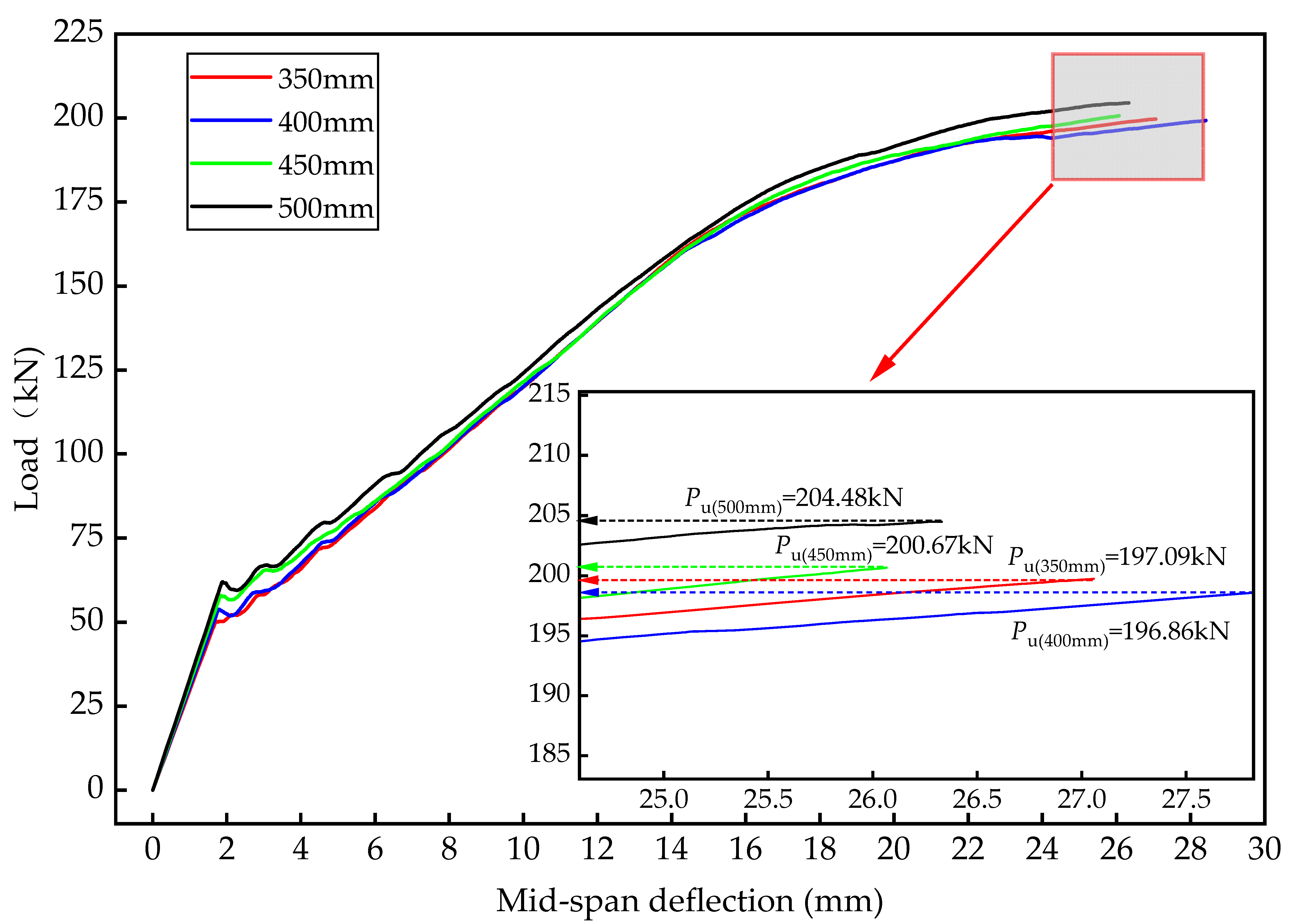
4.1. Influence of the Deck Width on the Bending Bearing Capacity

The deck width has a certain effect on the bending bearing capacity, which is the larger the width, the higher the bending capacity, but too wide of a deck will significantly increase the structural deadweight and, at the same time, lead to unfavorable local stresses on the deck. Therefore, it is necessary to analyze the correlation between the deck width and the bending bearing capacity. According to the experience of similar projects, combined with the standardized manufacturing dimensions of components, the deck width was taken as 350 mm, 400 mm, 450 mm, and 500 mm for variable parameter analysis, and the numerical simulation results are shown in Figure 5.
From Figure 5, it can be concluded that the deck width is positively correlated with the bending bearing capacity, and the bending bearing capacity increases with the increase of the deck width, but the enhancement is not large. The bending bearing capacity of the 350 mm deck width is 196.86 kN, which has a 0.12% increase compared to the 197.09 kN of the 400 mm deck width. The bending bearing capacity of the 450 mm deck width is 200.67 kN, which is about 1.9% higher than that of the 400 mm deck width, and the bending bearing capacity of the 500 mm deck width is 204.48 kN, which is about 1.9% higher than that of the 450 mm deck width.
In addition, the concept of unit-mass bearing capacity (bearing capacity/self-weight of unit length component) was used to comprehensively consider the adverse effects of self-weight increase on bridge decks. The results are shown in Table 4.
It can be concluded from Table 3 that the increase in deck width does not significantly promote the bending bearing capacity, but the increase in deck width will increase the self-weight, leading to unfavorable local stresses in the deck. Therefore, the recommended deck width is within the range of 350 mm to 400 mm.

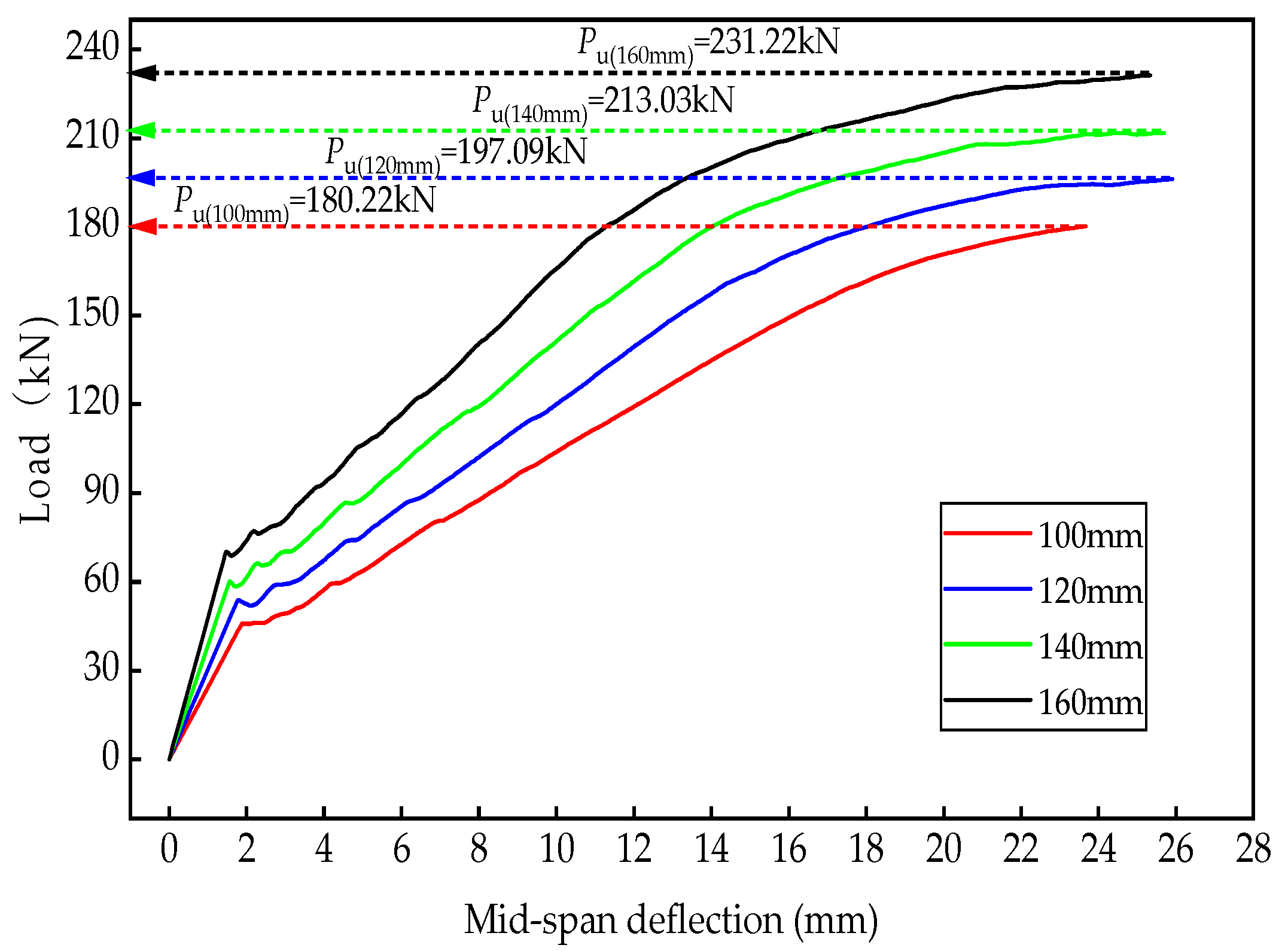
4.2. Influence of Flange Thickness on the Bending Bearing Capacity

The flange thickness has a certain influence on the bending bearing capacity and stiffness. The larger the flange thickness, the larger the bending bearing capacity and stiffness, but too large a flange thickness will significantly increase the structural deadweight, and at the same time have a negative impact on clearance under the bridge. Therefore, it is necessary to analyze the correlation between the flange thickness and the bending bearing capacity. According to the experience of similar projects, combined with the standardized manufacturing dimensions of components, the flange thickness was taken as 100 mm, 120 mm, 140 mm, and 160 mm for variable parameter analysis, and the numerical simulation results are shown in Figure 6.
From Figure 6, it can be concluded that the flange thickness is positively correlated with the bending bearing capacity, the bending bearing capacity increases with the increase of the flange thickness, and the magnitude of the increase is larger. The bending bearing capacity of 100 mm flange thickness is 180.22 kN, which has a 9.4% decrease compared to 197.09 kN of 120 mm flange thickness. The bending bearing capacity of 140 mm flange thickness is 213.03 kN, which is 8.5% higher than that of 120 mm flange thickness, and the bending bearing capacity of 160 mm flange thickness is 231.22 kN, which is 8.1% higher than that of 140 mm flange thickness. The calculation results are shown in Table 5.
From the above analysis, it can be seen that when the flange thickness exceeds 120 mm, the ratio of the improvement of the bending bearing capacity will be reduced. At the same time, too large a flange thickness will significantly increase the structural deadweight and have a negative impact on the clearance under the bridge. Therefore, considering the effects of bending bearing capacity and deadweight, the recommended flange thickness is within the range of 100 mm~120 mm.

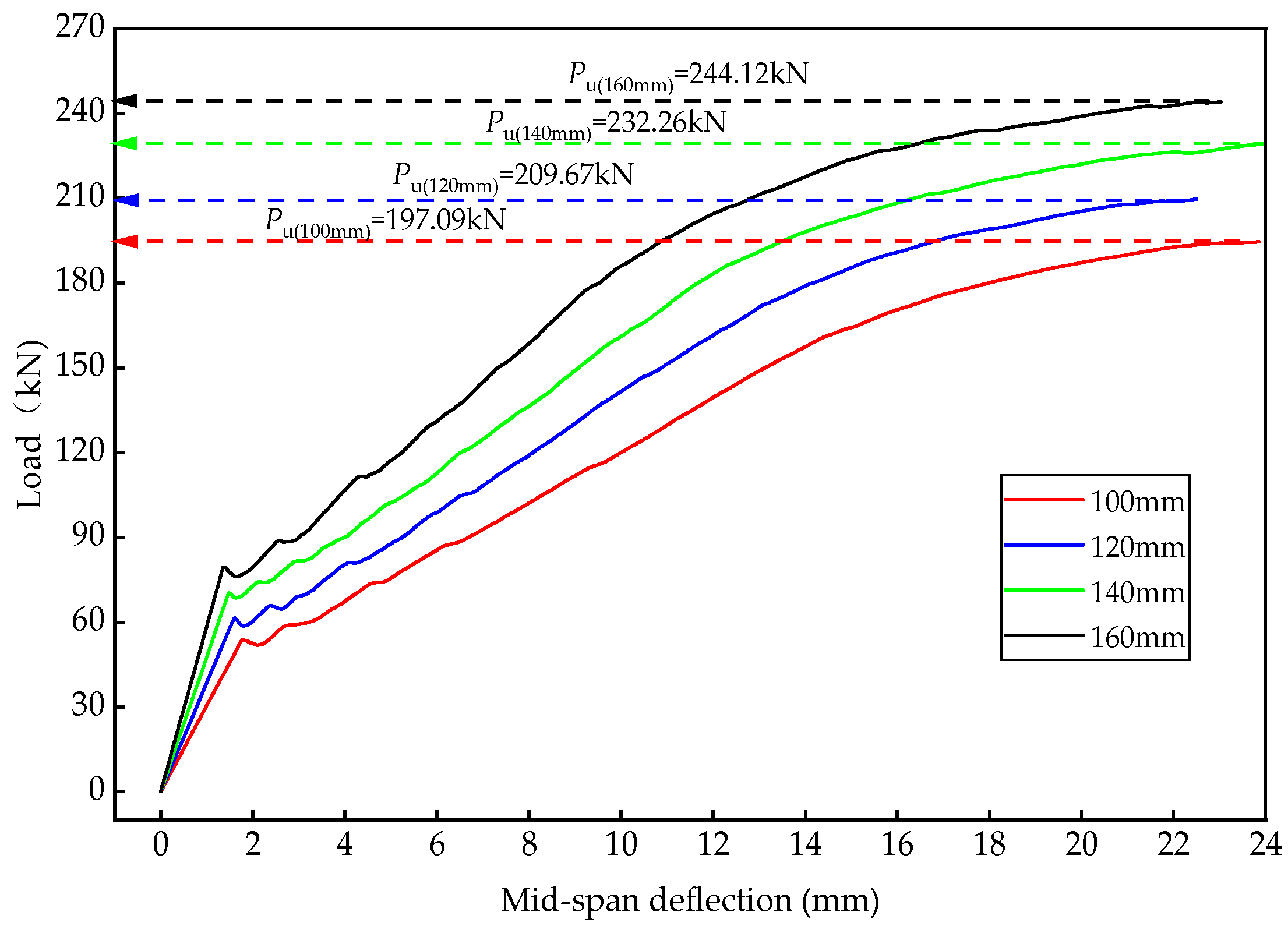
4.3. Influence of Web Height on the Bending Bearing Capacity

The web height also has an effect on the bending bearing capacity and stiffness of the bridge deck. The higher the web height, the greater the bending bearing capacity and stiffness, but too large a web height will significantly increase the deck deadweight, and at the same time have an unfavorable effect on the under-bridge clearance. Therefore, it is necessary to analyze the correlation between web height and bending bearing capacity. According to the experience of similar projects, combined with the standardized manufacturing dimensions of components, web heights of 100 mm, 120 mm, 140 mm, and 160 mm were taken for variable parameter analysis, and the numerical simulation results are shown in Figure 7.
From Figure 7, it can be concluded that the web height is positively correlated with the bending bearing capacity of the bridge deck, and the bending bearing capacity increases with the increase of the web height. The bending bearing capacity of 100 mm web height is 197.09 kN, which is decreased by 6.4% compared to 209.67 kN of 120 mm web height. The bending bearing capacity of 140 mm web height is 232.26kN, which is 11% higher than that of 120 mm web height. The bending bearing capacity of 160 mm web height is 242.26 kN, which is 5.2% higher than that of 140mm web height. Calculation results are shown in Table 6.
From the above analysis, it can be seen that when the web height exceeds 120 mm, the magnitude of the bending bearing capacity increase will be decreased. At the same time, too large a flange thickness will significantly increase the structural deadweight and also have a negative impact on the clearance under the bridge. Therefore, considering the effects of bending bearing capacity and deadweight, the recommended web height is within the range of 120 mm~140 mm.

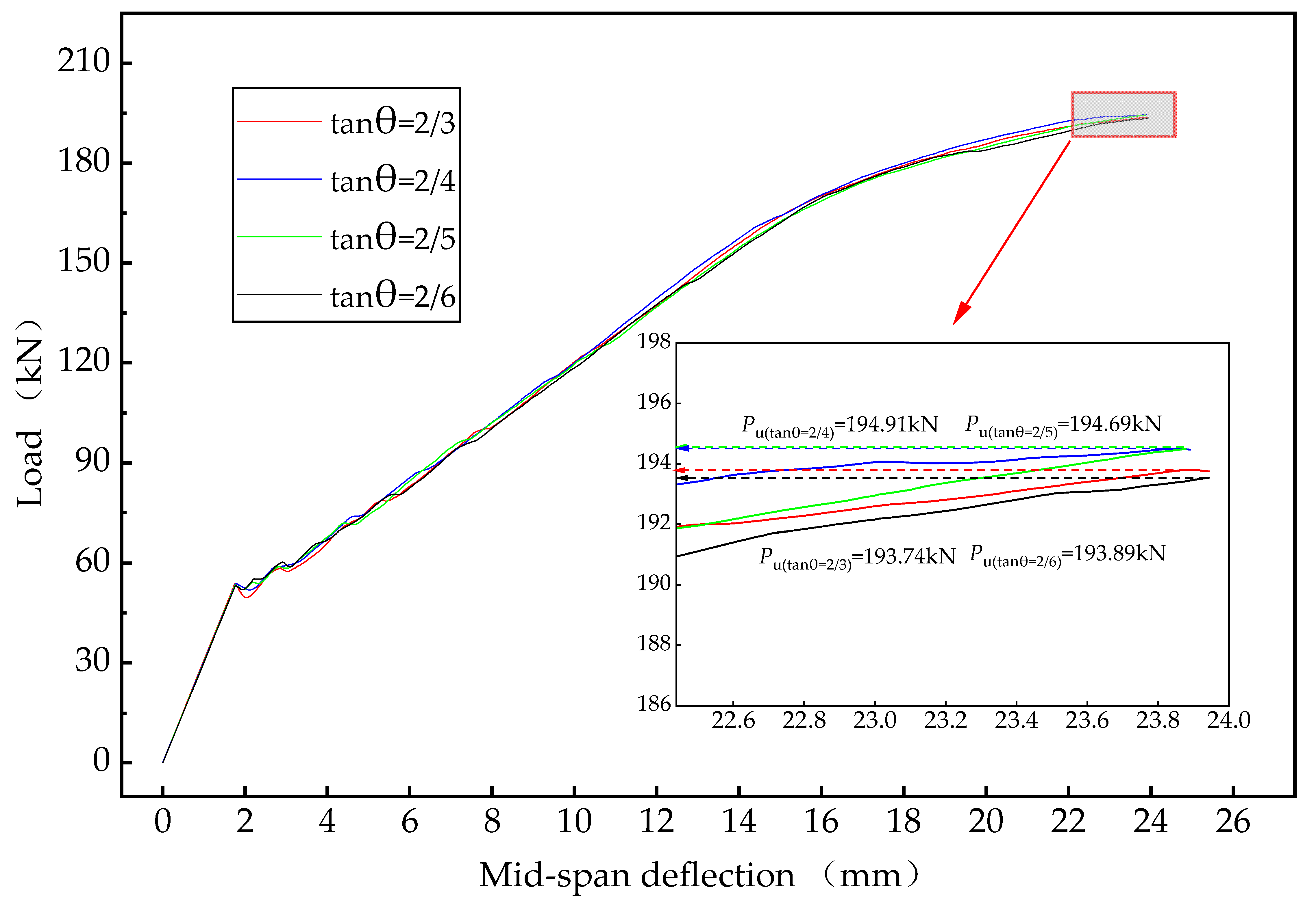
4.4. Influence of Web Horizontal Inclination Angle on the Bending Bearing Capacity

The web horizontal inclination angle has a certain effect on the neutral axis position, self-weight, and local stress of the bridge deck. The smaller the web horizontal inclination angle, the lower the neutral axis position, and the larger the bending bearing capacity. However, too small of a web horizontal inclination angle will significantly increase the structural deadweight. Therefore, it is necessary to analyze the correlation between the web’s horizontal inclination angle and the bending bearing capacity. According to the experience of similar projects, combined with the standardized manufacturing dimensions of components, the tangent values of the web horizontal inclination angle were taken as 2/3, 2/4, 2/5, and 2/6 for variable parameter analysis, and the numerical simulation results are shown in Figure 8.
From Figure 8, it can be concluded that the web horizontal inclination angle has a certain effect on the bending bearing capacity as, with the reduction of the web horizontal inclination angle, the bending bearing capacity shows a trend of increasing first and then decreasing. The bending bearing capacity of the 2/3 tangent value of the web horizontal inclination angle is 193.74 kN, which is decreased by 0.6% compared to 194.91 kN of the 2/4 tangent value of the web horizontal inclination angle. The bending bearing capacity of the 2/5 tangent value of the web horizontal inclination angle is 194.69 kN, which is about 0.1% lower than that at 2/4. The bending bearing capacity of the 2/6 tangent value of the web horizontal inclination angle is 193.89 kN, which is 0.4% lower than that of 2/5. At the same time, different web horizontal inclination angle has little effect on the deadweight of the bridge. From the above analysis, it can be seen that when the tangent value of the web horizontal inclination angle is within the range of 2/4~2/5, the bridge deck has a high bending bearing capacity.

5. Theoretical Analysis

The new steel grating–UHPFRC composite bridge deck under negative bending moment is calculated by simplified plasticity theory, which explains that when the bridge deck reaches the limit state of bearing capacity, the cross-section materials have entered the plasticity, and the stress distribution of the cross-section can be regarded as a rectangular distribution. The results of the numerical study show that when the new steel grating–UHPFRC composite bridge deck reaches the limit state of load-bearing capacity, the bottom plate of the “丄” shaped steel is yielded by pressure, part of the web is yielded by tensile, and part of the bottom concrete reaches the limit of the compressive strain. So, it can be specified as a “steel plate-concrete composite bridge deck” [40], using the simplified plasticity design method to calculate the bending bearing capacity of the new steel grating–UHPFRC composite bridge deck under negative bending moment.
Under the action of negative bending moment, the use of simplified plasticity theory for bending bearing capacity calculation needs to meet the following assumptions:
1.
At the limit state of bearing capacity, the strain of the bridge deck cross-sectional satisfies the flat section assumption.
2.
The perforated web of the “丄” shaped steel can effectively transfer the shear force between the “丄 “shaped steel and concrete.
3.
The UHPFRC in the tensile zone above the plastic neutral axis enters a tensile plastic hardening state and is uniformly stretched. The plastic tensile strength is taken as the design value of tensile strength, while the UHPFRC in the compressive zone below the plastic neutral axis is uniformly compressed, and the compressive stress is taken as the design value of compressive strength.
4.
The steel of the “丄 “shaped steel web in the tensile zone is uniformly subjected to tension, and the tensile stress is taken as the design value of tensile strength. The steel of the “丄 “shaped steel web in the compressive zone and the “丄 “shaped steel roof is uniformly compressed, and the compressive stress is taken as the design value of compressive strength.
In order to facilitate the formula derivation of bending bearing capacity, the combined force of the bottom plate and web of the “丄” shaped steel, and the combined force of the top plate and web of the UHPFRC, are considered separately. According to the numerical simulation results, the neutral axis of the bridge deck under the negative moment is, basically, in the UHPFRC web, as shown in Figure 4.
The neutral axis of the section is located in the UHPFRC web, and the internal forces in each part of the section are calculated as follows:
The moment of the compressive stress in the compression zone of the “丄” shaped steel roof on the neutral axis is shown in Equation (3).
M rc = f cd t 2 B   ( h 1 + h 2 x + t 2 / 2 )
The moment of the compressive stress in the compression zone of the “丄” shaped steel web on the neutral axis is shown in Equation (4).
M wc = f cd t 1 H t 2 x ( H x t 2 2 )
The moment of the compressive stress in the compression zone of the UHPFRC on the neutral axis is shown in Equation (5).
M cc = f c d H t 2 x 2 b 1 + H t 2 x tan θ H x t 2 3 3 b 1 + x h 1 tan θ 2 b 1 + x h 1 tan θ
The moment of the tensile stress in the tensile zone of the “丄” shaped steel on the neutral axis is shown in Equation (6).
M wt = f sd t 1 x H h x H + h 2
The moment of the tensile stress in the tensile zone of the UHPFRC web on the neutral axis is shown in Equation (7).
M cwt = f td x h 1 b 2 b 2 x h 1 tan θ t 1 x h 1 3 2 b 4 b 2 2 t 1 + 2 b 1 + 2 x h 1 tan θ b 2 b 2 t 1 + 2 b 1 + 2 x h 1 tan θ
The moment of the tensile stress in the tensile zone of the UHPFRC flange on the neutral axis is shown in Equation (8).
M cft = f td b h 1 t 1 h t 2 h 2 x h 1 2
The moment of the tensile stress in the tensile zone of longitudinal rebars on the neutral axis is shown in Equation (9).
M rt = 1 4 f d π d 2 x y
In the above formulas, fcd is the design value of UHPFRC compressive strength, ftd is the design value of UHPFRC tensile strength, fsd is the design value of steel tensile strength, and other parameters are the same as before.
According to the equilibrium of the internal forces in the section, the height of the compression zone can be determined. Then, by taking the moment of each combined force to the neutral axis, the bending bearing capacity Mu can be obtained by Equation (10):
M u = M rc + M wc + M cc + M wt + M cwt + M cft + M rt
Using MATLAB to develop a program to calculate the above formulas, the results were compared with the numerical simulation results in the previous section, as shown in Table 7.
As can be seen from Table 7, the bending bearing capacity of the bridge deck calculated by simplified plasticity theory is close to the numerical simulation results, and the maximum relative deviation is 9.1%, which verifies the accuracy of the theoretical formula and numerical model. The theoretical results are smaller than the numerical simulation results because the theoretical calculation assumes that the bridge deck reaches the limit state of bearing capacity when the whole cross-section reaches the plastic strain, and the bridge deck cannot continue to carry the load. In the numerical simulation process, the edge material of the bridge deck often reaches the plastic strain first, and the cross-section can continue to bear the load until the whole cross-section reaches the plastic strain. So, the bearing capacity of numerical simulation results is higher than the theoretical results. However, the bending bearing capacity calculated by the simplified plasticity theory is on the safe side, which is favorable to the bridge deck.

6. Cost–Benefit Analysis and Environmental Impact Assessment

6.1. Cost–Benefit Analysis

The cost–benefit analysis between the new steel grating–UHPFRC combined bridge deck and conventional steel grating–UHPC combined bridge deck is shown in Table 8. The geometric dimensions of the new steel grating–UHPFRC combined bridge deck and conventional steel grating–UHPC combined bridge deck are the same, which are shown in Table 9.
According to Table 8, the new steel grating–UHPFRC combined bridge deck has increased in quality and cost compared to conventional steel grating–UHPC combined bridge deck under the same geometric dimensions. The mass has increased by about 25% and the cost has increased by about 11%, but the deflection has decreased by 48% and the ultimate bearing capacity has increased by 12%. Therefore, the stiffness and strength of the new steel grating–UHPFRC combined bridge deck structure are greatly improved, with a minimal cost increase. It can be considered that the new steel grating–UHPFRC combined bridge deck has a good cost–benefit.

6.2. Environmental Impact Assessment

Due to space limitations, the comparative study of this paper on the environmental impact assessment of new steel grating–UHPFRC composite bridge deck and conventional steel grating–UHPC composite bridge deck is limited to two technical indicators, energy consumption and greenhouse gas emissions, during the raw material preparation stage and construction stage. Based on the previous on-site research results and relevant references, the energy consumption and greenhouse gas emissions of the new composite bridge deck and the traditional composite bridge deck during the raw material preparation stage and construction stage are shown in Table 10 and Table 11.
According to Table 10 and Table 11, the energy consumption and carbon emissions during the raw material preparation stage of conventional steel grating–UHPC combined bridge deck are higher than those of new steel grating–UHPFRC combined bridge deck. In the new steel grating–UHPFRC combined bridge deck, steel bars, steel fibers, and cement are the most energy-intensive substances in the raw material preparation stage, while steel bars, cement, and asphalt matrix are the most carbon-intensive substances. During the construction phase, the use of a new steel grating–UHPFRC combined bridge deck reduces energy consumption and carbon emissions. The characteristic values of both aspects are significantly lower than those of conventional steel grating–UHPC combined bridge decks that only use epoxy asphalt pavement layers. In the numerical comparison of environmental impact assessment characteristics between the above two bridge decks, excavators and EAC pavers are the two main contributing factors to environmental impact. This is because both bridge deck systems require repeated replacement of the epoxy asphalt layer to varying degrees throughout the entire lifecycle of the bridge deck system.

7. Conclusions

1.
The bending bearing capacity of the new steel grating–UHPFRC composite bridge deck in the negative bending moment zone increases with the increase of the width of the bridge deck, the thickness of the UHPFRC flange, and the height of the UHPFRC web. As the horizontal inclination angle of the web decreases, it shows a trend of first increasing and then decreasing. The improvement of the bending bearing capacity of the bridge deck in the width is limited.
2.
Taking into account the bending bearing capacity, structural self-weight, local stress, and clearance requirements under the bridge, the reasonable structural parameters for the new steel grating–UHPFRC composite bridge decks are recommended as follows: the width of the bridge deck should be within the range of 350 mm to 400 mm, the thickness of the flange should be within the range of 120 mm to 140 mm, the height of the web should be within the range of 140 mm to 160 mm, and the tangent value of the horizontal inclination angle of the web should be within the range of 2/4 to 2/5.
3.
The calculation formula for the bending bearing capacity of a new steel grating–UHPFRC composite bridge deck in the negative bending moment zone, derived based on simplified plasticity theory, has high accuracy. Compared with the numerical simulation results, the maximum relative deviation is 9.1%, and the theoretical calculation results are smaller than the numerical simulation results, making the calculation of the bending bearing capacity safer and beneficial to the bridge deck stress.
4.
The energy consumption and carbon emissions during the raw material preparation stage of conventional steel grating–UHPC combined bridge deck are higher than those of new steel grating–UHPFRC combined bridge deck, and during the construction phase, the use of new steel grating-UHPFRC combined bridge deck reduces energy consumption and carbon emissions.

Author Contributions

Methodology, Z.L.; Formal analysis, H.Y.; Investigation, J.M.; Resources, J.Z.; Writing—original draft, J.M. and Z.L.; Writing—review and editing, Z.L. All authors have read and agreed to the published version of the manuscript.

Funding

This research was funded by the Fundamental Research Funds for the Central Universities, Chang’an University (300102213522), the General Program of Shanxi Province Natural Science Foundation, Shanxi Provincial Department of Science and Technology (202203021221025), and the Science and Technology Innovation Program of Shanxi Province Higher Education Institutions, Shanxi Provincial Department of Education (2021L010).

Data Availability Statement

The raw data supporting the conclusions of this article will be made available by the authors upon request.

Conflicts of Interest

Authors Jianyong Ma, Haoyun Yuan and Jiahao Zhang were employed by the company CCCC Second Highway Engineering Co., Ltd. The remaining author declares that the research was conducted in the absence of any commercial or financial relationships that could be construed as a potential conflict of interest.

References

  1. Zhang, H.P.; Liu, H.J.; Kuai, H.D. Stress intensity factor analysis for multiple cracks in orthotropic steel decks rib-to-floorbeam weld details under vehicles loading. Eng. Fail. Anal. 2024, 164, 108705. [Google Scholar] [CrossRef]
  2. Ma, Y.H.; Wang, B.J.; Chen, A.R. Inspection data-based prediction on fatigue crack of orthotropic steel deck using interpretable machine learning method. Fatigue Fract. Eng. Mater. Struct. 2024, 47, 3874–3893. [Google Scholar] [CrossRef]
  3. Liu, J.H.; Zheng, F.T.; Shen, W.; Li, D.S. Monitoring fatigue damage of orthotropic steel decks using nonlinear ultrasonic waves. Materials 2024, 17, 2792. [Google Scholar] [CrossRef] [PubMed]
  4. Wang, B.J.; He, P.H.; Ma, Y.H.; Wang, D.L.; Chen, A. Fatigue failure criteria for OSDs considering penetrating cracks and effects on pavements. J. Constr. Steel Res. 2024, 219, 108774. [Google Scholar] [CrossRef]
  5. Lu, D.Y. Analysis of structural parameters of U-rib orthotropic anisotropic combination bridge deck slabs. Urban Roads Bridges Flood Control 2023, 5, 190–194+24. [Google Scholar]
  6. Sun, R.X.; Zhe, X.M. Parametric analytical study on the form of stiffening ribs for steel box girder bridge deck slabs. Highway 2023, 68, 154–158. [Google Scholar]
  7. Tian, K.; Zeng, Z.B.; Wang, X.W. Optimisation of construction parameters of orthotropic anisotropic steel bridge decks. Railw. Eng. 2019, 59, 34–38. [Google Scholar]
  8. Wu, H.L.; Li, C.K.; Yu, J.S.; Song, M. Structural optimization of orthotropic steel bridge deck with transverse and internal partitions. J. Harbin Inst. Technol. 2023, 55, 16–24. [Google Scholar]
  9. Shi, Z.; Zhou, Y.C.; Sun, Z.T.; Yang, S.L. Fatigue performance of orthotropic steel decks in a wide steel-box girder. J. Constr. Steel Res. 2022, 190, 107109. [Google Scholar] [CrossRef]
  10. Xu, X.L.; Qian, S.B.; Li, H.T.; Wu, C.; Wang, R.G.; Li, Q.; Ding, X.G.; Li, Z.J.; Li, X.H. Comparative experimental study on fatigue performance of new open-rib orthotropic steel bridge panels. J. Civ. Eng. 2024. [Google Scholar] [CrossRef]
  11. Wu, L.L.; An, L.P.; Sun, T.M. Selection and analysis of new orthotropic steel bridge deck. J. Xi’an Univ. Archit. Technol. (Nat. Sci. Ed.) 2020, 52, 771–778+796. [Google Scholar]
  12. Natsheh, S.H.; Menzemer, C.C. Built-up closed-rib steel orthotropic bridge deck. Civ. Eng. 2022, 3, 960–978. [Google Scholar] [CrossRef]
  13. Abdulla, W.; Menzemer, C. Finite element analysis of heavy duty riveted steel grating bridge deck. Civ. Eng. 2021, 2, 485–501. [Google Scholar] [CrossRef]
  14. Zafar, M.N.; Saleem, M.A.; Xia, J.; Saleem, M.M. Experimental characterization of prefabricated bridge deck prepared with prestressed and sustainable ultra-high performance concrete. Appl. Sci. 2020, 10, 5132. [Google Scholar] [CrossRef]
  15. Luo, J.; Zheng, L.; Pei, B.; Wang, Y.; Yan, H.; Zhao, J. Key design parameters analysis and calculation theory research on bending performance of steel–UHPC lightweight composite deck. Buildings 2023, 13, 504. [Google Scholar] [CrossRef]
  16. Zhang, X.J. Performance analysis and application of steel-UHPC composite bridge deck. Shanxi Transp. Sci. Technol. 2019, 3, 79–83. [Google Scholar]
  17. Xiang, Z. Research on Rational Construction of Steel-UHPC Composite Orthotropic Bridge Deck; Hunan University: Changsha, China, 2020. [Google Scholar]
  18. Liu, X.H.; Zhou, C.; Zhang, J.R.; Li, L.F.; Shi, X.W. Stress performance test of steel-UHPC composite beams in the negative moment zone. Chin. J. Highw. 2020, 33, 110–121. [Google Scholar]
  19. Shao, X.D.; Cao, J.H. Future-oriented development and application of high-performance bridge structures. J. Build. Sci. Eng. 2017, 34, 41–58. [Google Scholar]
  20. Hu, J.; Gu, Y.; Yan, J.; Sun, Y.; Huang, X. Experimental study on flexural resistance of UHPC wet joint precast reinforced concrete bridge deck with variable cross-section. Appl. Sci. 2024, 14, 3028. [Google Scholar] [CrossRef]
  21. Abbas, Y.M.; Shafiq, N.; Fares, G.; Osman, M.; Khan, M.I.; Khatib, J.M. Strength iso-responses of shear-deficient ultra-high performance fiber reinforced concrete beams. Sustainability 2023, 15, 4265. [Google Scholar] [CrossRef]
  22. Ding, N.; Shao, X.D. Fatigue performance of lightweight composite bridge deck. J. Civ. Eng. 2015, 48, 74–81. [Google Scholar]
  23. Gu, P.; Lu, F.; Zhang, C.; Ma, J. Fatigue performance of steel-UHPC composite bridge deck. J. Shenyang Univ. Archit. (Nat. Sci. Ed.) 2021, 37, 1–8. [Google Scholar]
  24. Liu, G.G. Research on structural parameters of steel-UHPC combined bridge deck slabs. Urban Roads Bridges Flood Control 2024, 2, 206–213+21. [Google Scholar]
  25. Liu, G.G.; Zhang, W.; Zhou, Y.G. Force characteristics of steel-UHPC-plain concrete combined bridge deck and force characteristics with different thickness ratios. China Munic. Eng. 2023, 5, 89–94+126. [Google Scholar]
  26. Sun, Y.; Wang, H.R.; Wang, F.; Pang, X. Optimisation of structural cross-section of corrugated steel-UHPC composite bridge deck. J. Ningbo Univ. (Nat. Sci. Eng. Ed.) 2020, 33, 105–110. [Google Scholar]
  27. Zhang, Q.H.; Cheng, Z.Y.; Liao, G.X.; Bu, Y.Z. Optimised design of corrugated top plate-UHPC composite bridge deck. J. Southwest Jiaotong Univ. 2018, 53, 670–678. [Google Scholar]
  28. Zhao, H.J. Study on Bearing Capacity of Corrugated Steel-Reinforced Concrete Combination Bridge Deck; East China Jiaotong University: Chengdu, China, 2012. [Google Scholar]
  29. Shao, X.D.; Cai, W.Y.; Cao, J.H.; Liu, M.L. Study on section steel-UHPC lightweight combination bridge deck and its flexural performance. J. Civ. Eng. 2024, 57, 152–168. [Google Scholar]
  30. Shao, X.D.; Zhang, S.T.; Zhang, L.; Ouyang, Z.H. Research on the performance of steel-ultra-thin UHPC layer lightweight composite bridge deck. J. Chongqing Jiaotong Univ. (Nat. Sci. Ed.) 2016, 35, 22–27+75. [Google Scholar]
  31. Zhao, H.J.; Xu, H.Y.; Xu, J.Q. Experimental study on bearing capacity of corrugated steel a reinforced concrete composite bridge deck. Shanxi Archit. 2011, 37, 157–158. [Google Scholar]
  32. Qiu, M.; Shao, X.; Yan, B.; Zhu, Y.; Chen, Y. Flexural behaviour of UHPC joints for precast UHPC deck slabs. Eng. Struct. 2022, 251, 113422. [Google Scholar] [CrossRef]
  33. Shan, Y.; Chen, Y.; Zong, Z.; Li, J.; Li, Z.; Xu, Y. Structural performance of orthotropic steel-concrete continuous composite decks with larger U-ribs and PBL shear connectors. Structures 2023, 51, 1030–1051. [Google Scholar] [CrossRef]
  34. Liu, R.; Zhao, H.; An, J.H. Bending performance test and finite element analysis of steel-UHPC composite bridge deck. J. Railw. Sci. Eng. 2023, 20, 628–640. [Google Scholar]
  35. He, H. Study on the Stress Performance of Corrugated Steel-Concrete Combination Bridge Deck Slabs; Chongqing Jiaotong University: Chongqing, China, 2021. [Google Scholar]
  36. Yang, X.; He, J.J.; Hu, D.Y.; Xiao, B.J.; Wang, N.B. Numerical simulation study on the shear performance of bolt-PBL joints in corrugated steel-UHPC composite bridge deck. J. Railw. Sci. Eng. 2024, 21, 697–708. [Google Scholar]
  37. Guo, S.; He, X.; He, H.; Li, Z.; Zeng, Y.; Tan, H.; Zhou, J. Study on shear resistance and structural performance of corrugated steel–concrete composite deck. Appl. Sci. 2023, 13, 10112. [Google Scholar] [CrossRef]
  38. GB 50010-2010; Code for Concrete Structure Design. Ministry of Housing and Urban Rural Development of the People’s Republic of China: Beijing, China, 2010.
  39. Cui, W. Seismic performance study of section steel concrete columns for fully indoor substations. Electr. Power Surv. Des. 2020, 12, 53–59. [Google Scholar]
  40. GB 50917-2013; Design Specification for Steel Concrete Composite Bridges. Ministry of Housing and Urban Rural Development of the People’s Republic of China: Beijing, China, 2013.
Figure 1. Schematic diagram of new steel grating–UHPFRC composite bridge deck.
Buildings 14 02857 g001
Figure 2. The steel constitutive relationship curve.
Buildings 14 02857 g002
Figure 3. Finite element model of the new steel grid–UHPFRC composite bridge deck.
Buildings 14 02857 g003
Figure 4. The structural parameters of new steel grating–UHPFRC composite bridge deck.
Buildings 14 02857 g004
Figure 5. Load-mid-span deflection curves for different deck widths.
Buildings 14 02857 g005
Figure 6. Load-mid-span deflection curves for different flange thicknesses.
Buildings 14 02857 g006
Figure 7. Load-mid-span deflection curves for different web heights.
Buildings 14 02857 g007
Figure 8. Load-mid-span deflection curves for different values of tangent of web horizontal inclination angle.
Buildings 14 02857 g008
Table 1. UHPFRC mixing ratios (unit: kg/m3).
CementCoal AshSandCrushed StoneSteel FiberPolyacrylonitrile
Fiber
WaterWater Reducing Agent
5 mm~10 mm10 mm~25 mm
400100756398596951.11607.5
Table 2. Mechanical performance of UHPFRC.
Compressive Strength (MPa)Flexural Strength
(MPa)
28d Axial Tensile Strength (MPa)Modulus of Elasticity
7 d28 d7 d28 d6.5441,800
50.360.37.49.8
Table 3. Mechanical performance of steel.
Modulus of ElasticityYield Strength (MPa)Ultimate Strength (MPa)
206,000345630
Table 4. Comparison of concrete slab width parameters.
Concrete slab width (mm)350400450500
Ultimate load capacity (kN)196.86197.09200.67204.48
Self-weight (kg)161.25176.25191.25206.25
Load capacity per unit mass (kN/kg)1.221.121.050.99
Table 5. The influence of flange thickness on the bearing capacity.
Concrete flange thickness (mm)100120140160
Bending bearing capacity (kN)180.22197.09213.03231.22
Self-weight (kg)156.25176.25196.25216.25
Bearing capacity per unit mass (kN/kg)1.151.121.081.07
Table 6. The influence of web height on the bearing capacity.
Web height (mm)100120140160
Bending bearing capacity (kN)197.09209.67232.26244.12
Self-weight (kg)176.25190.5205.75222
Load capacity per unit mass (kN/kg)1.121.101.131.10
Table 7. Comparison of theoretical results and numerical simulation results of bending bearing capacity.
Structural ParameterTheoretical ValuesNumerical Values
Pu/kN
Relative
Deviation
(③ − ②)/③
Mu/kN·m
Pu/kN
b = 350100.20178.92196.869.1%
b = 400102.97183.87197.096.6%
b = 450105.58188.54200.676.0%
b = 500109.25195.09204.484.6%
h1 =10092.26164.75180.228.6%
h1 =120102.97183.87197.096.7%
h1 = 140112.10200.17213.036.0%
h1 = 160123.00219.64231.215.0%
h2 = 100102.97183.87197.096.7%
h2 = 120111.05198.30209.675.4%
h2 = 140120.84215.78232.267.1%
h2 = 160131.27234.41244.124.0%
tanθ = 2/3103.17184.24194.145.1%
tanθ = 2/4102.97183.87197.096.7%
tanθ = 2/5102.64183.29196.916.9%
tanθ = 2/6102.55183.13193.895.5%
Note: The theoretical values of Mu in the table are the results calculated according to Formula (10) and Pu = 2Mu/a, a is the shear span, which is 1.12 m in this case.
Table 8. The cost–benefit analysis between the new steel grating–UHPFRC composite bridge deck and conventional steel grating–UHPC composite bridge deck.
ItemsNSCBD
CSCBD
Ratio
(①/②)
Mass (kg/m) 246.22197.091.25
Cost ($/m)116.62104.851.11
Deflection (mm)4.047.770.52
Bearing capacity (kN/kg)1.181.051.12
Note: NSCBD stands for new steel grating–UHPFRC composite bridge deck, and CSCBD stands for conventional steel grating–UHPC composite bridge deck.
Table 9. The geometric dimensions of the new steel grating–UHPFRC composite bridge deck and conventional steel grating–UHPC composite bridge deck.
Typeb (mm)h1 (mm)h2 (mm)tan θ
NSCBD3501401400.5
CSCBD3501401400.5
Note: NSCBD stands for new steel grating–UHPFRC composite bridge deck, and CSCBD stands for conventional steel grating–UHPC composite bridge deck.
Table 10. Environmental impact assessment of raw material preparation stage of new steel grating–UHPFRC composite bridge deck and conventional steel grating–UHPC composite bridge deck.
Raw MaterialEnergy Consumption (MJ)Greenhouse Gas Emissions (kg)
NSCBDCSCBDNSCBDCSCBD
Cement082,750018,900
steel bars0234,688029,301
steel fibers096,80007200
shear connectors027,16003409
water reducing agents038,24001709
crushed stone materials11382633,85019,6516799
asphalt matrix2159738346,82077,66112,017
summary2273564860,30893,85675,831
Note: NSCBD stands for new steel grating–UHPFRC composite bridge deck, and CSCBD stands for conventional steel grating–UHPC composite bridge deck.
Table 11. Environmental impact assessment of construction stage of new steel grating–UHPFRC composite bridge deck and conventional steel grating–UHPC composite bridge deck.
Raw MaterialEnergy Consumption (MJ)Greenhouse Gas Emissions (kg)
NSCBDCSCBDNSCBDCSCBD
Excavator103,51758,99333,49118,527
loader39,87421,36411,6427126
milling machine12859343226
vacuum cleaner48,69724,89715,7418324
welding machine0201052
concrete mixer022870741
EAC mixer73,56121,36922,6476854
plate vibrator,0152038
high-temperature steam curing machine0918702947
grooving machine010570407
EAC paver61,25439,56419,62012,647
roller21,95820,95174579761
summary350,146200,115111,03067,450
Note: NSCBD stands for new steel grating–UHPFRC composite bridge deck, and CSCBD stands for conventional steel grating–UHPC composite bridge deck.
Disclaimer/Publisher’s Note: The statements, opinions and data contained in all publications are solely those of the individual author(s) and contributor(s) and not of MDPI and/or the editor(s). MDPI and/or the editor(s) disclaim responsibility for any injury to people or property resulting from any ideas, methods, instructions or products referred to in the content.

