
Seismic Upgrading of the Heritage-Protected Reinforced Concrete Warehouse in Rijeka, Croatia


Abstract
:1. Introduction
2. Historical Context on Architecture and Construction in Rijeka, Croatia
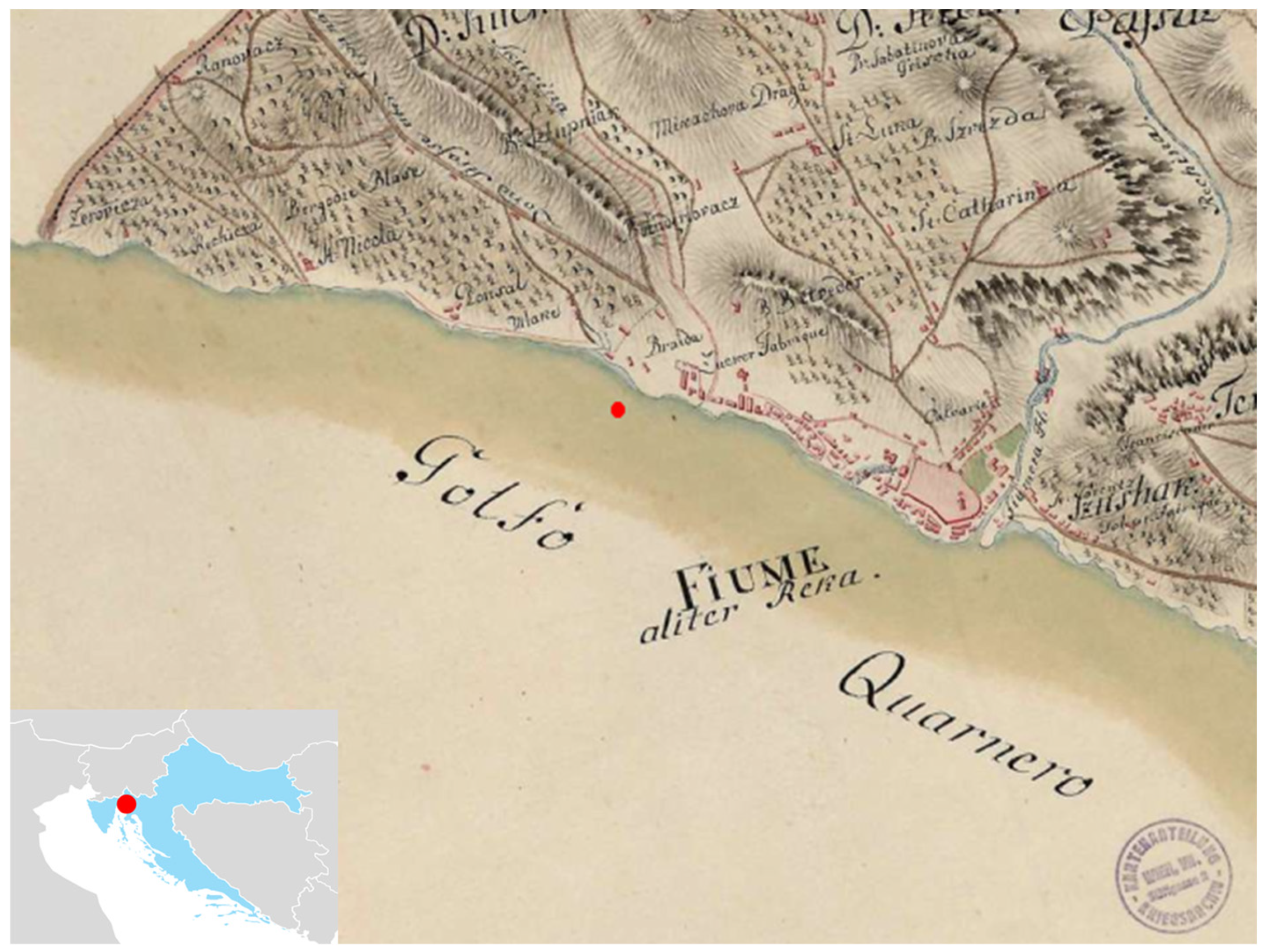
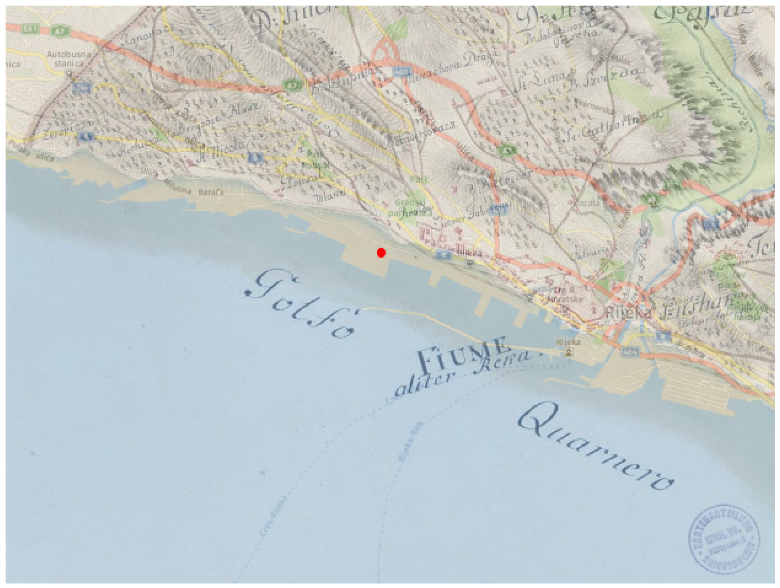
Local Conditions at the Beginning of the 20th Century
- 1872–1879—The first phase of the breakwater; construction began from east to west. There was a section for the railroad and a small port for the naval academy.
- 1880–1888—The completion of the central part of the breakwater, following the pier, the coast, and Petrolejska port.
- 1889–1894—The western part of the port–the port for wood and the completion of the breakwater [50],
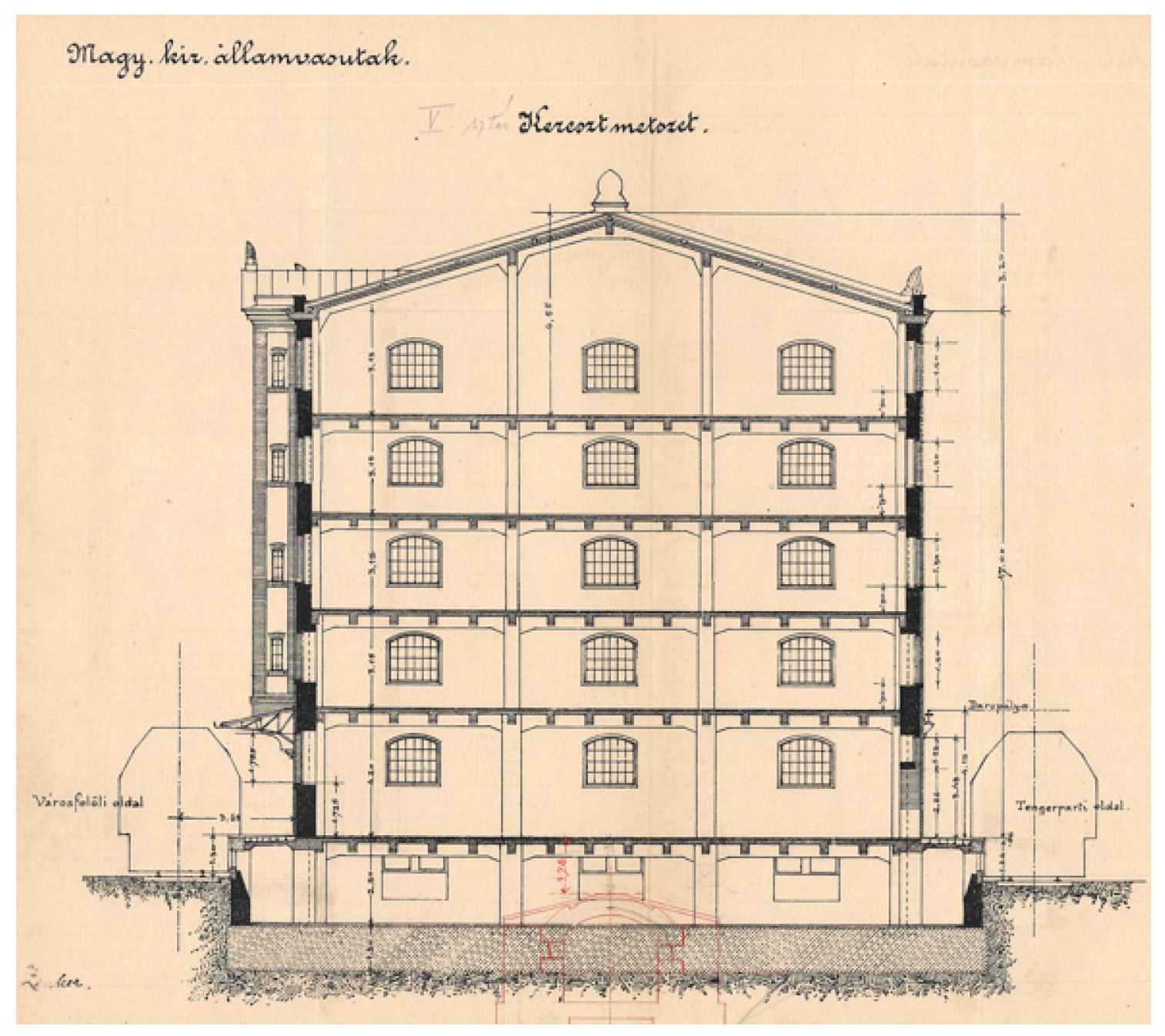
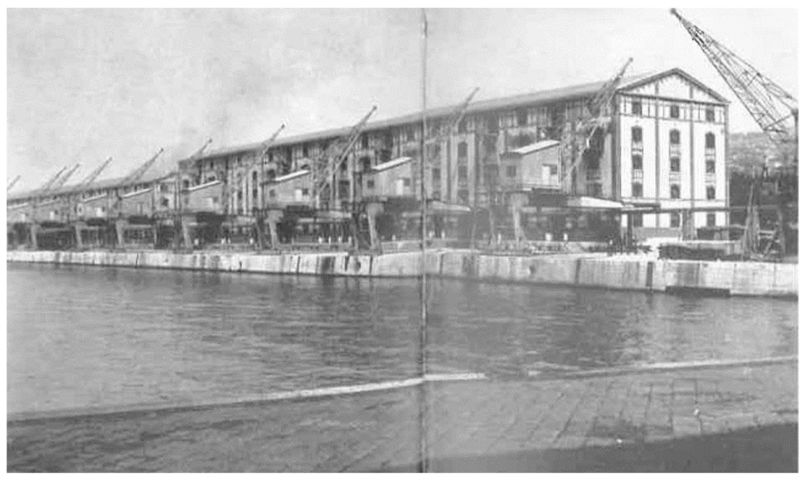
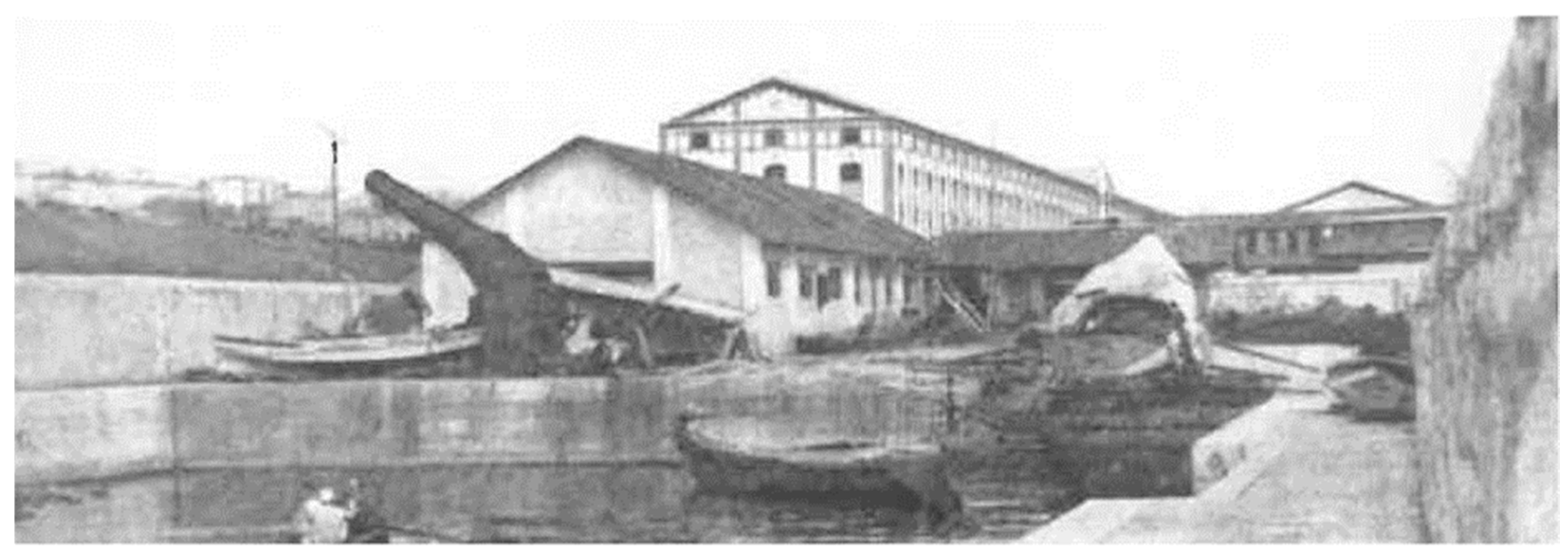
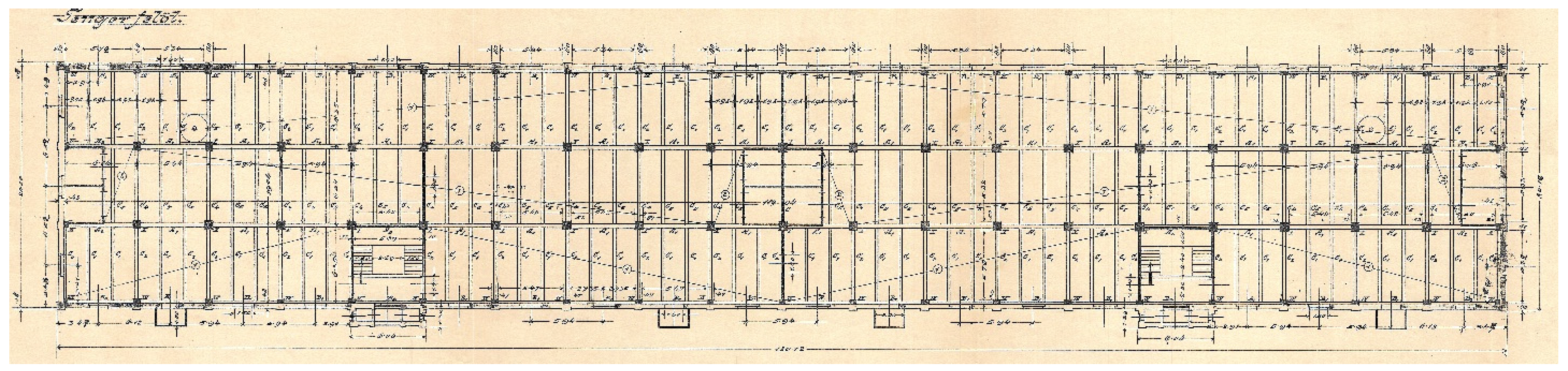
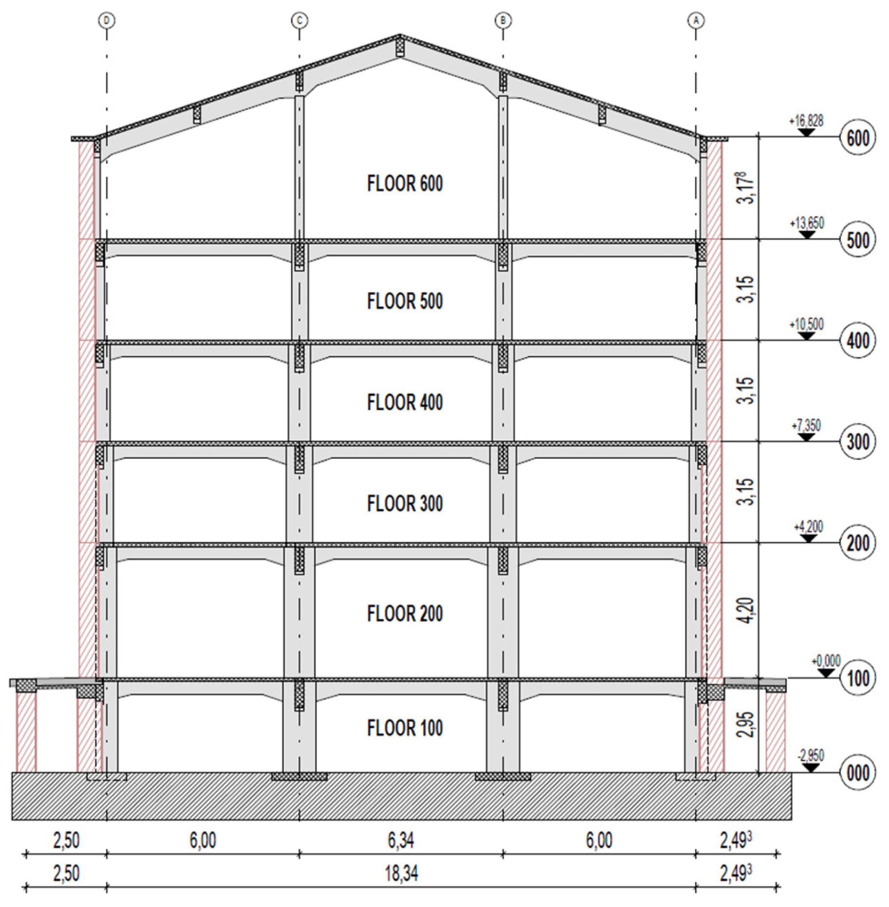
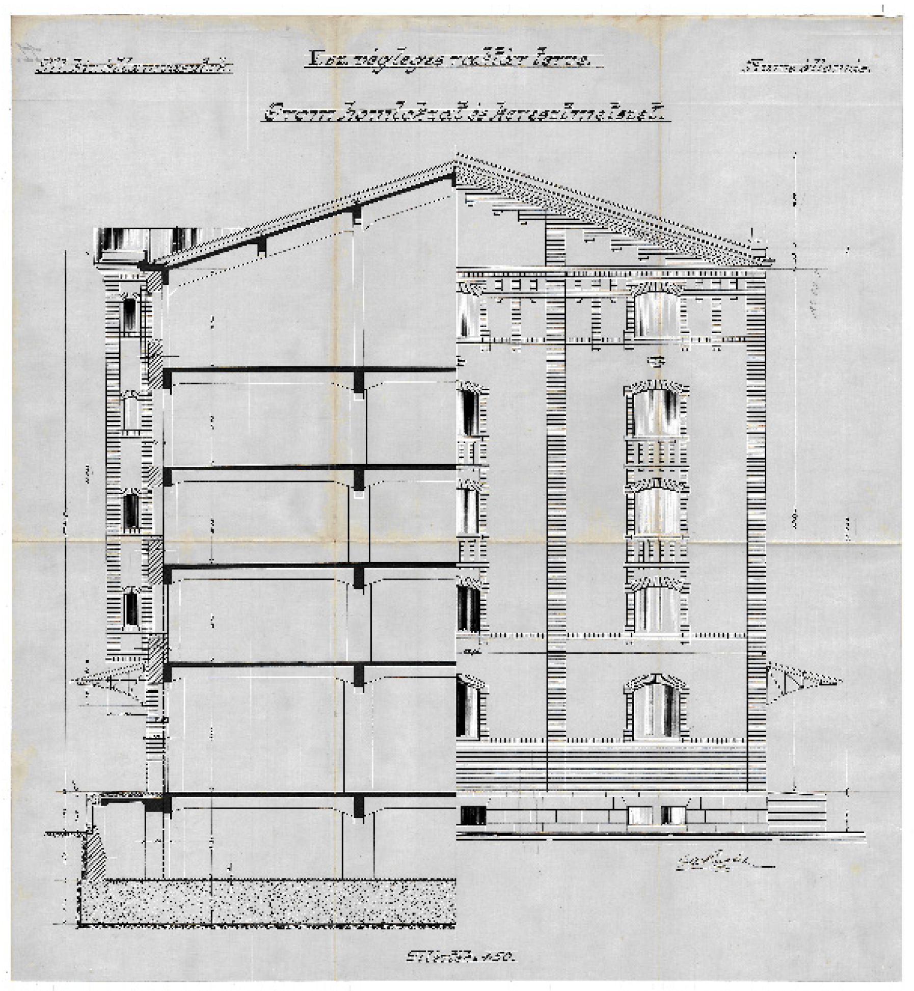
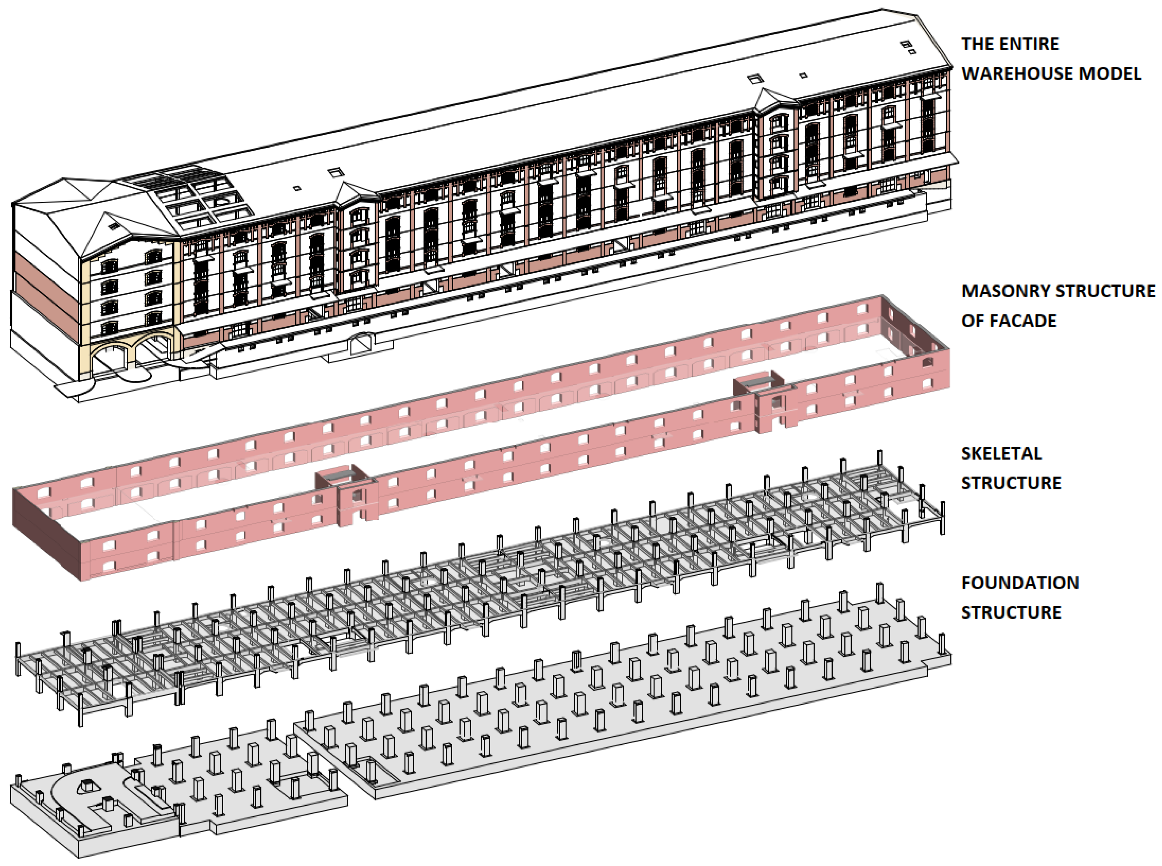
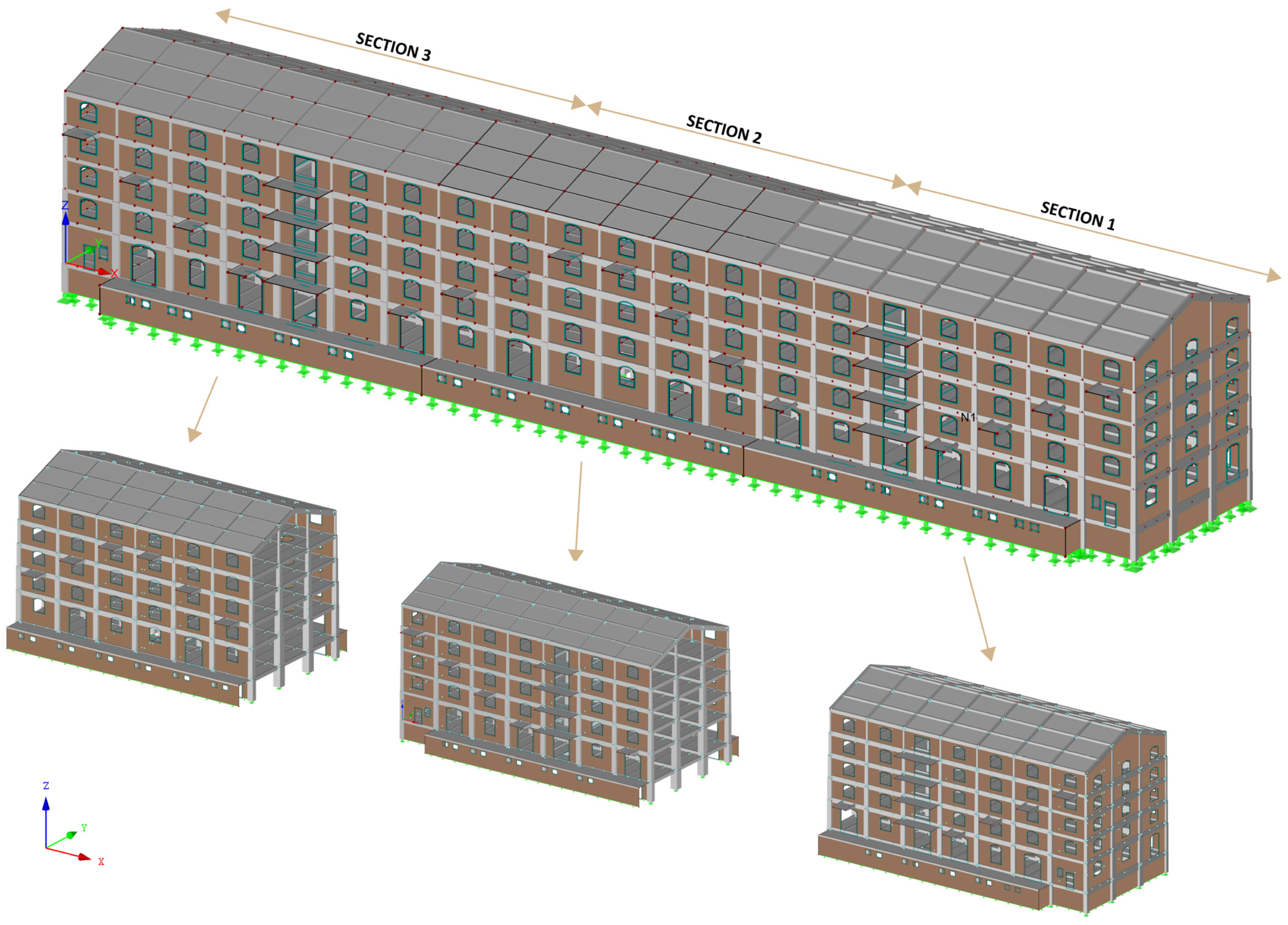
3. Case Study Building—Warehouse XXII
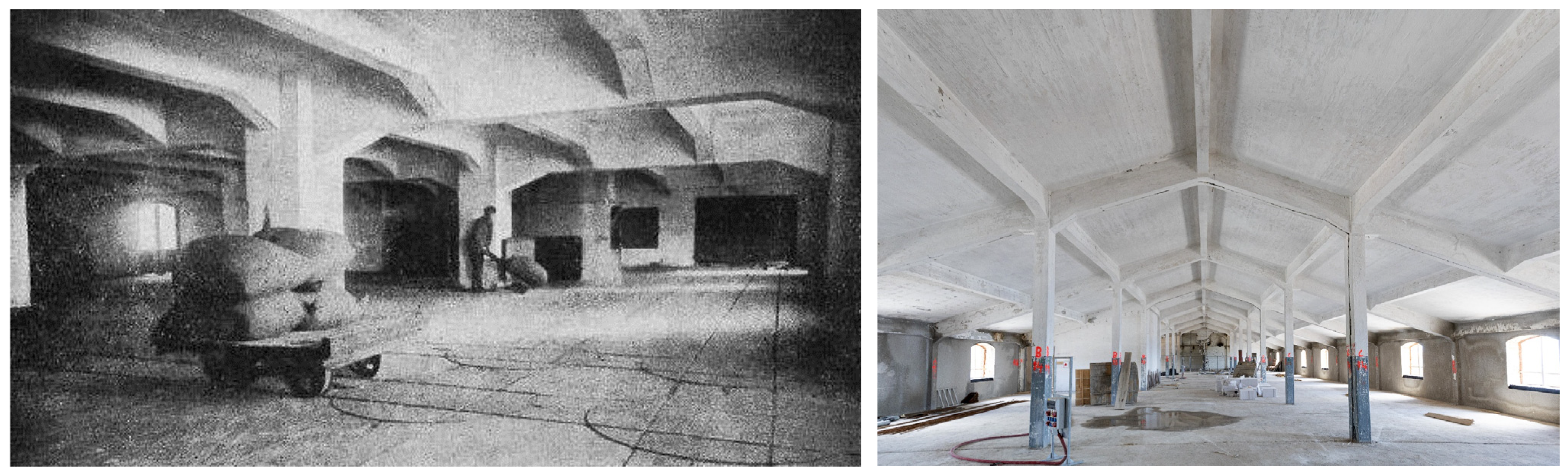
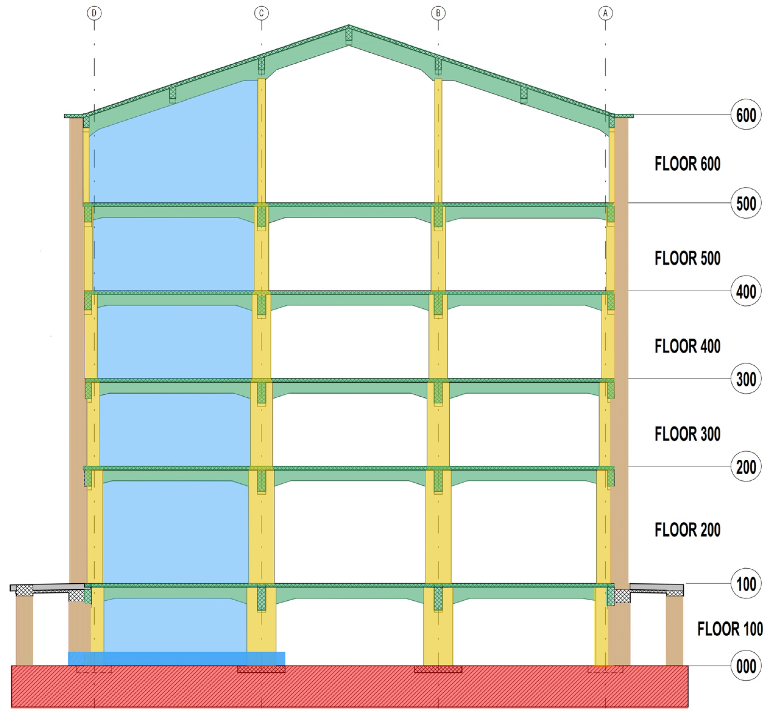
3.1. Structural Aspects of the Case Study
- Staircase cores (between the two world wars);
- Masonry lift shafts (1976);
- Enlargement of large entrance openings (in the second half of the 20th century);
- Additional layers of cast asphalt flooring, 3 cm thick (time unknown);
- Replacement of the roof tiles with tile metal sheeting.
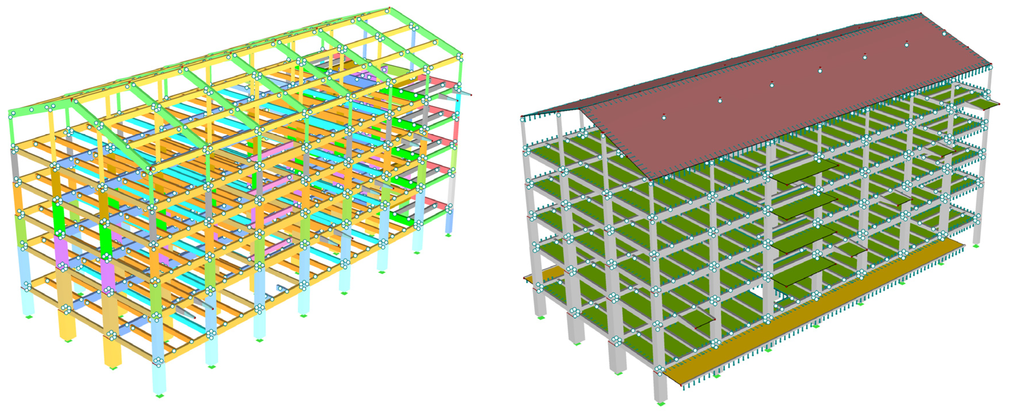
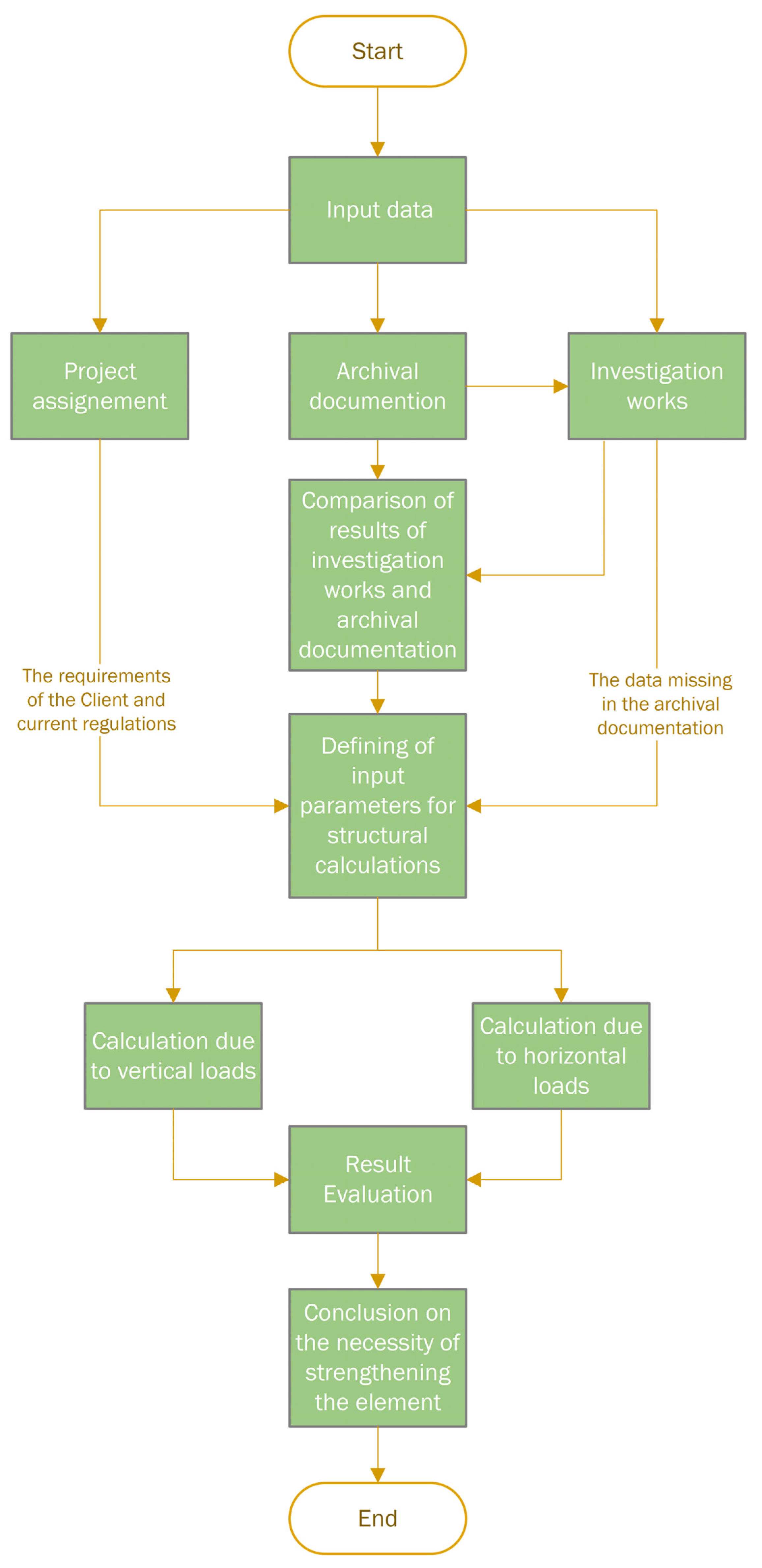
3.2. Preliminary Analysis of the Existing Structure
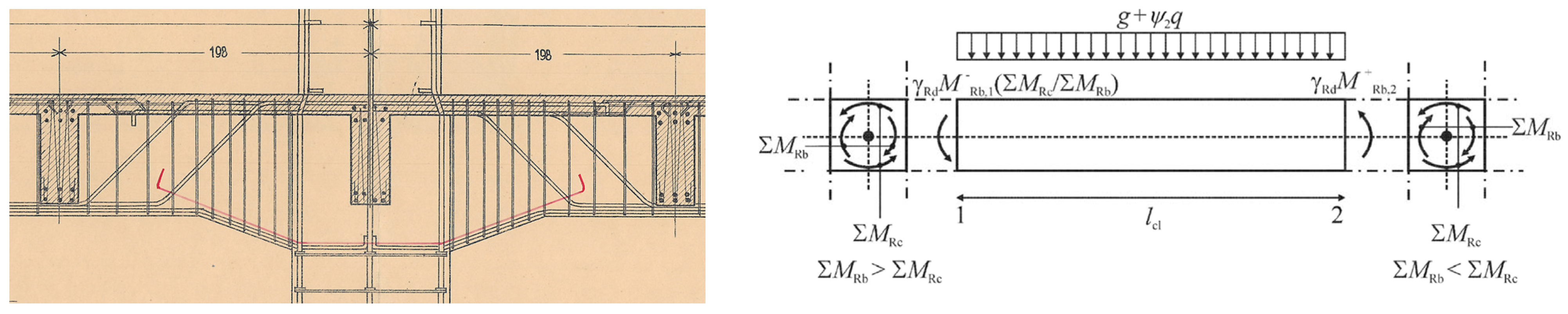
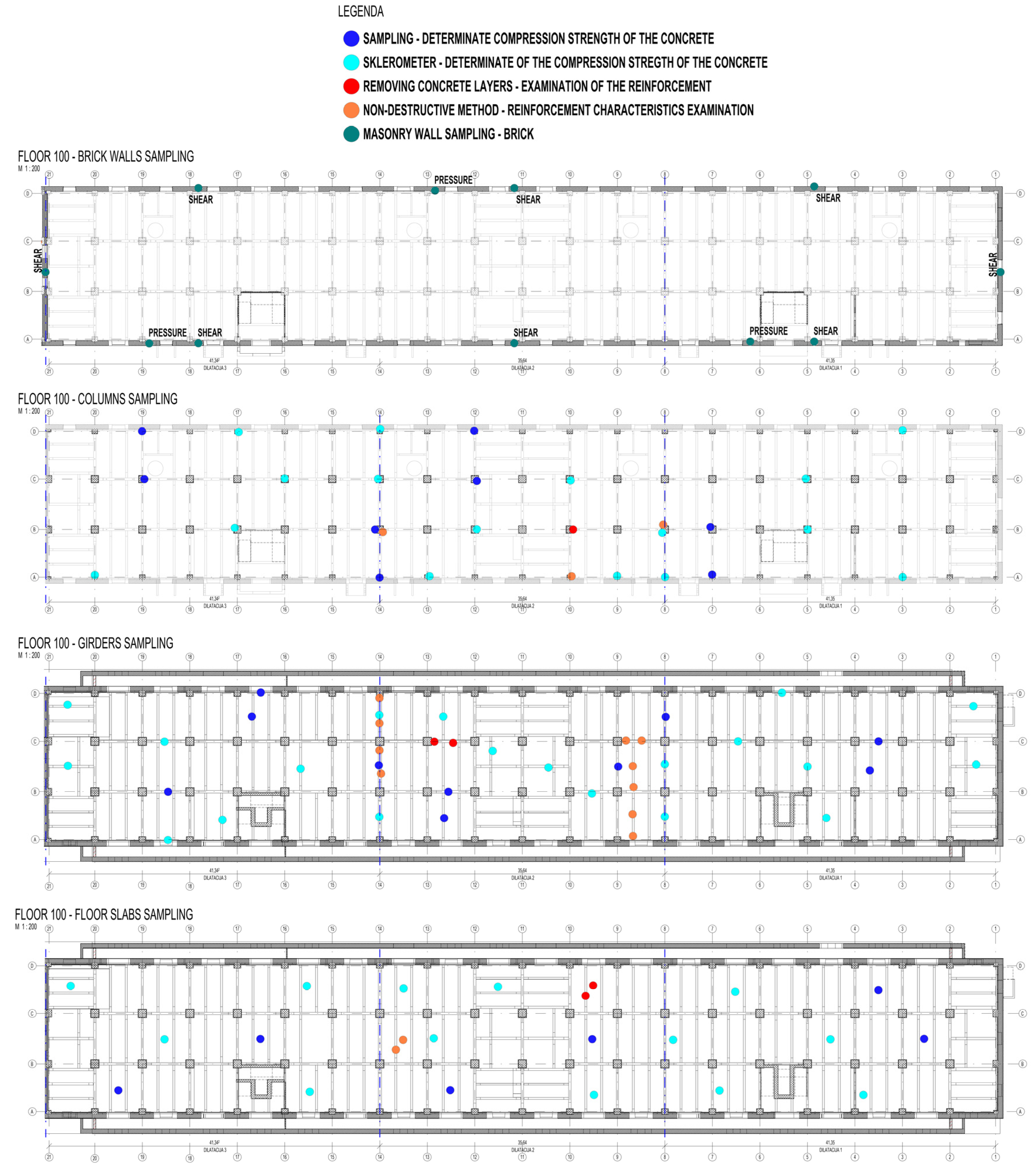
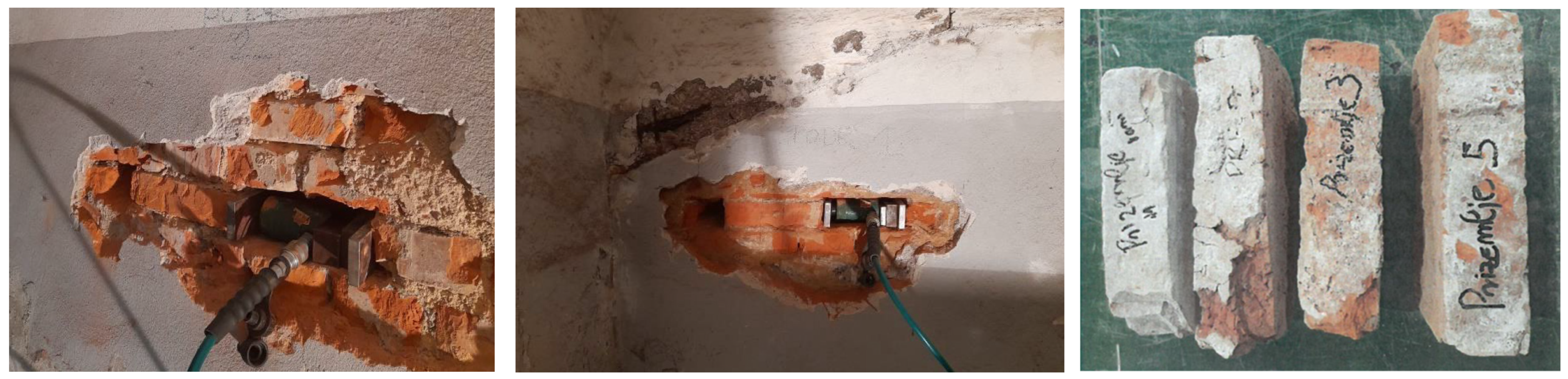
3.3. Investigation of Material Properties
- Compressive strength of the existing concrete;
- Protective layer of the reinforcement;
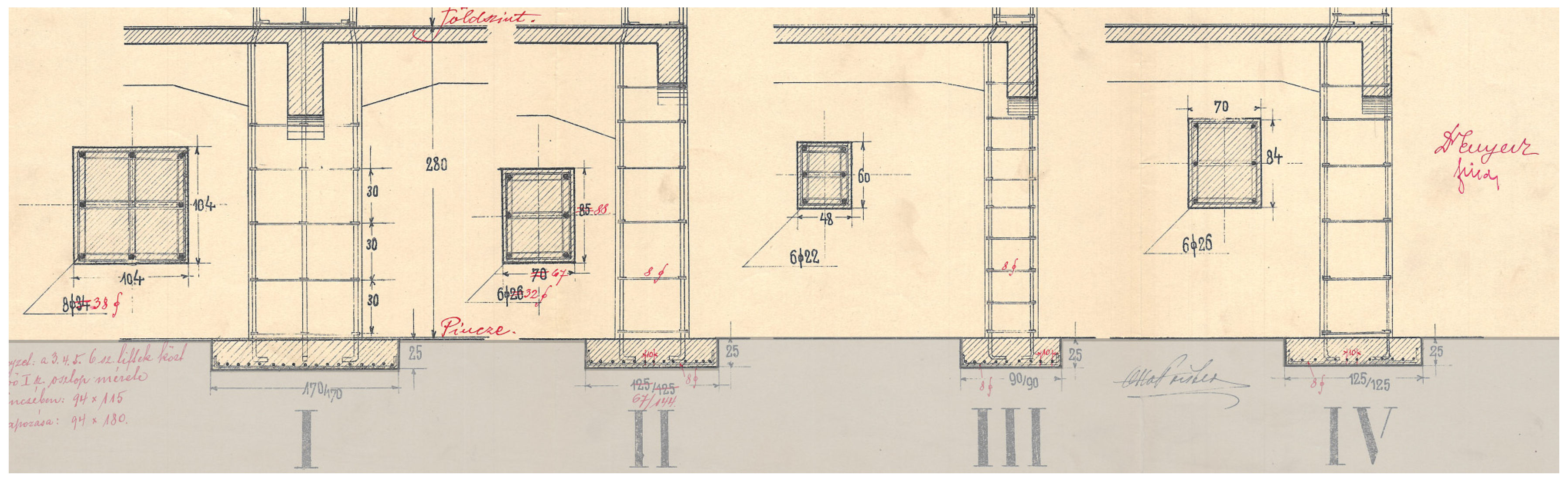
- Arrangement of the embedded reinforcement in the concrete elements;
- Corrosion of the reinforcement and quality of the reinforcement steel;
- Compressive and shear classification of the masonry;
- Compliance with the archival documentation.
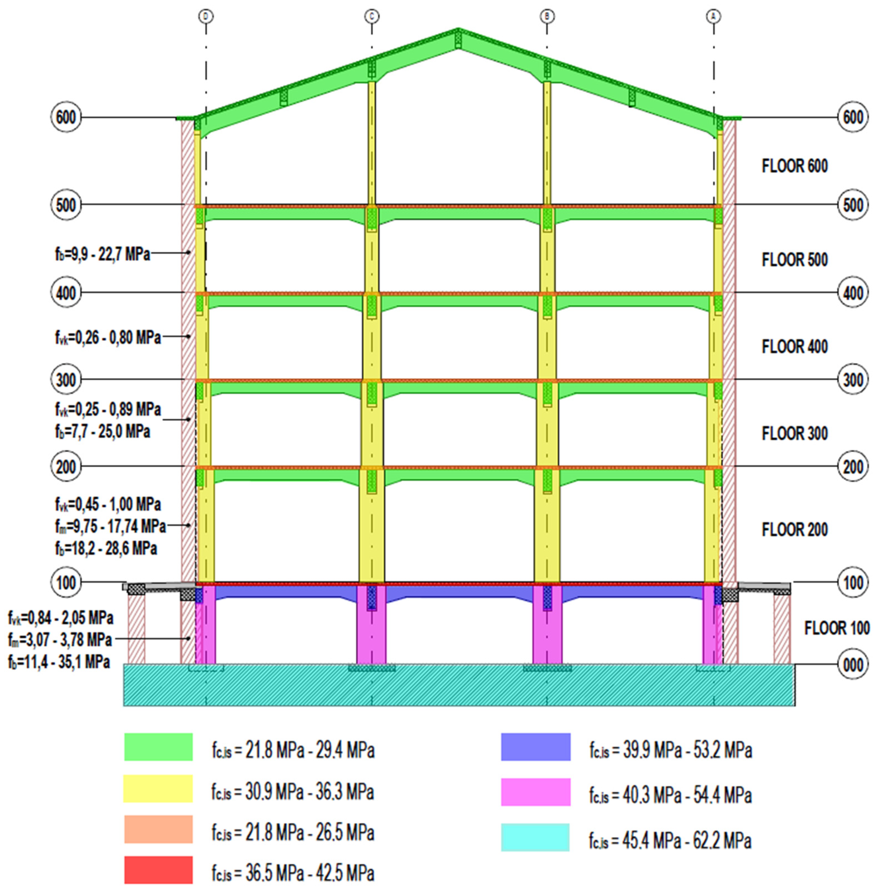
- 20 to 36 mm, with spacing between 37 and 48 mm (basement);
- 16 to 35 mm in diameter with spacing between 19 and 31 mm (ground floor);
- 23 to 28 mm, with 22 to 44 mm spacing (first floor);
- 20 to 32 mm, spaced 22 to 33 mm apart (second floor);
- 20 to 32 mm with 19 to 50 mm spacing (third floor);
- 10 to 16 mm with 18 to 25 mm spacing (fourth floor).
4. Design of Seismic Strengthening Methods
4.1. Analyses of Strengthening Methods
- Cultural heritage—the first complete RC structure of a warehouse in Croatia.
- Simplicity of execution.
- Functionality—the steel structure closes the openings on the façade.
- Feasibility of implementation and connection of existing and new structures.
- Financial feasibility—due to the cost of steel and fireproofing requirements.
4.2. Seismic Strengthening
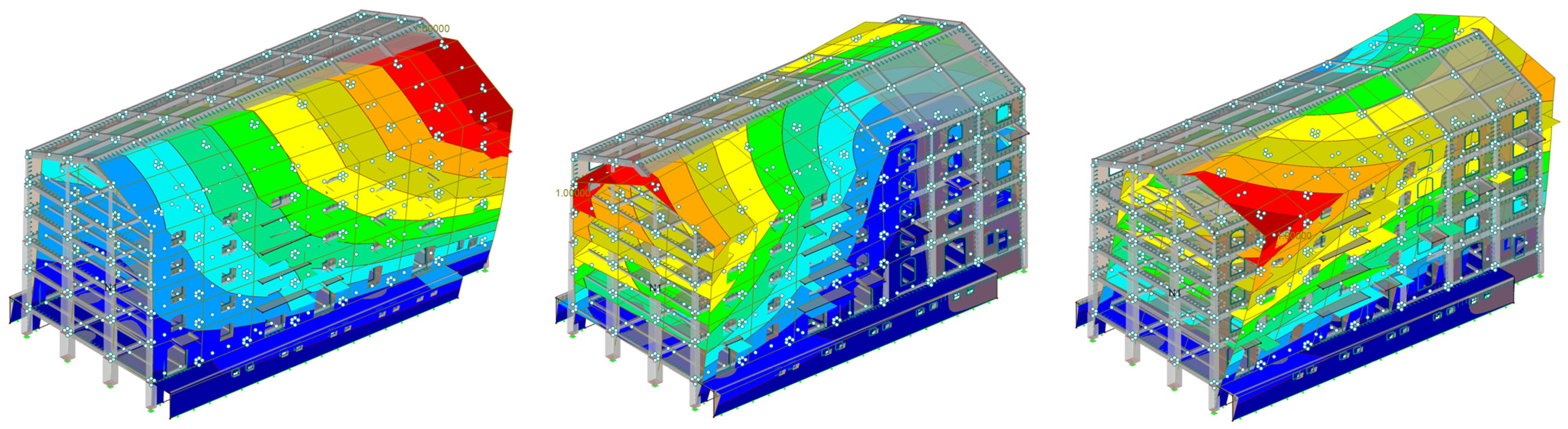
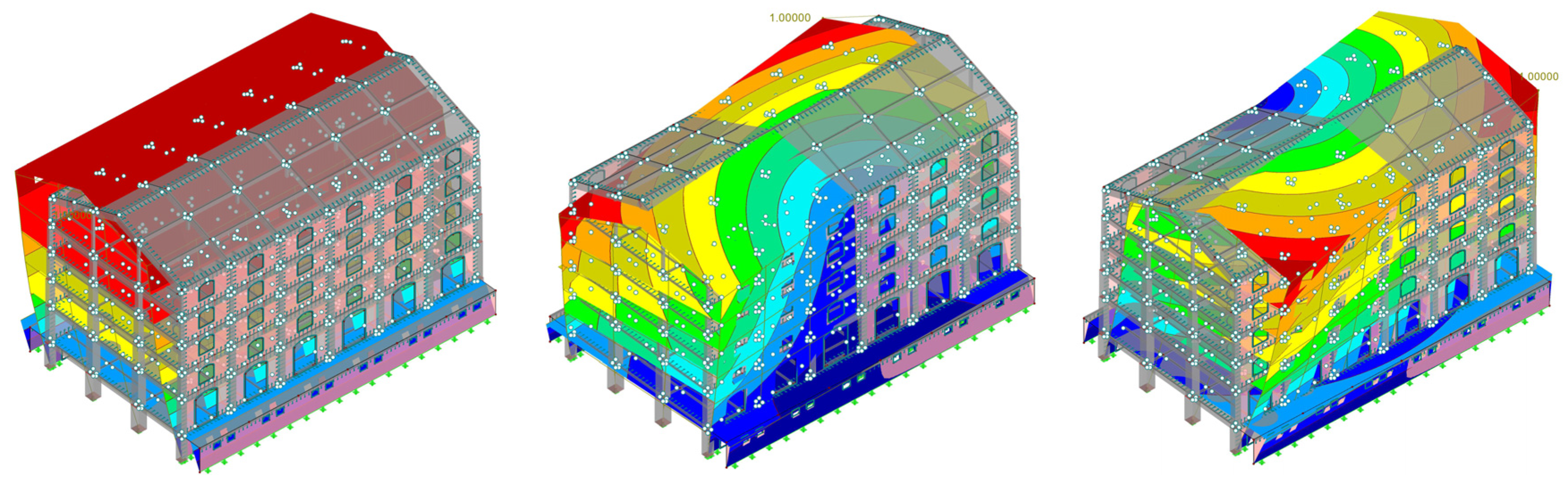
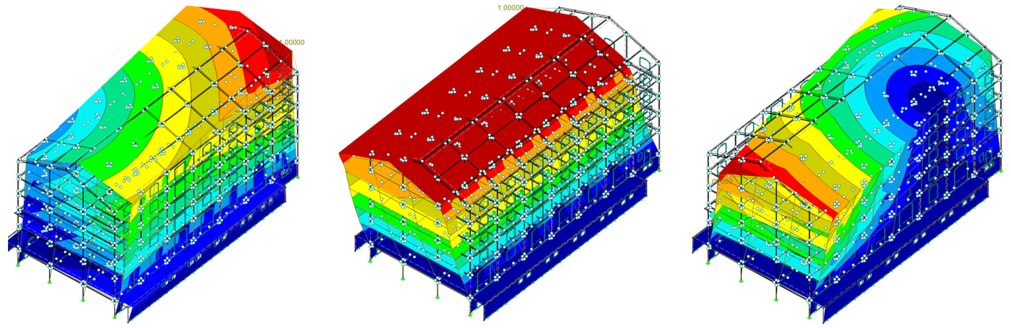
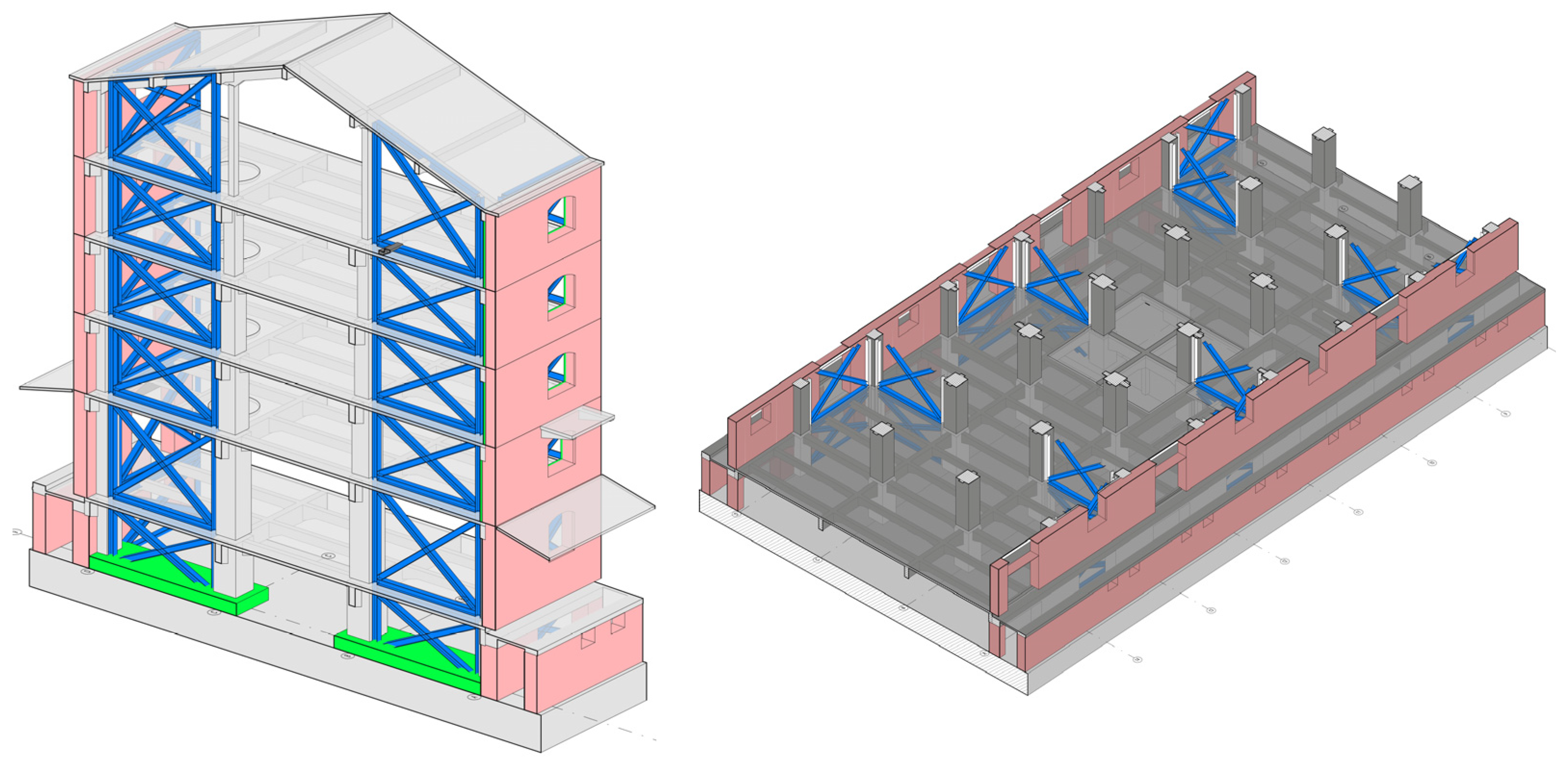
4.2.1. Analyses and Design of the New Proposed Structure
- System: Dual system
- Ductility class: DCM
- Nominal ground acceleration: agR = 0.202 g (475 years)
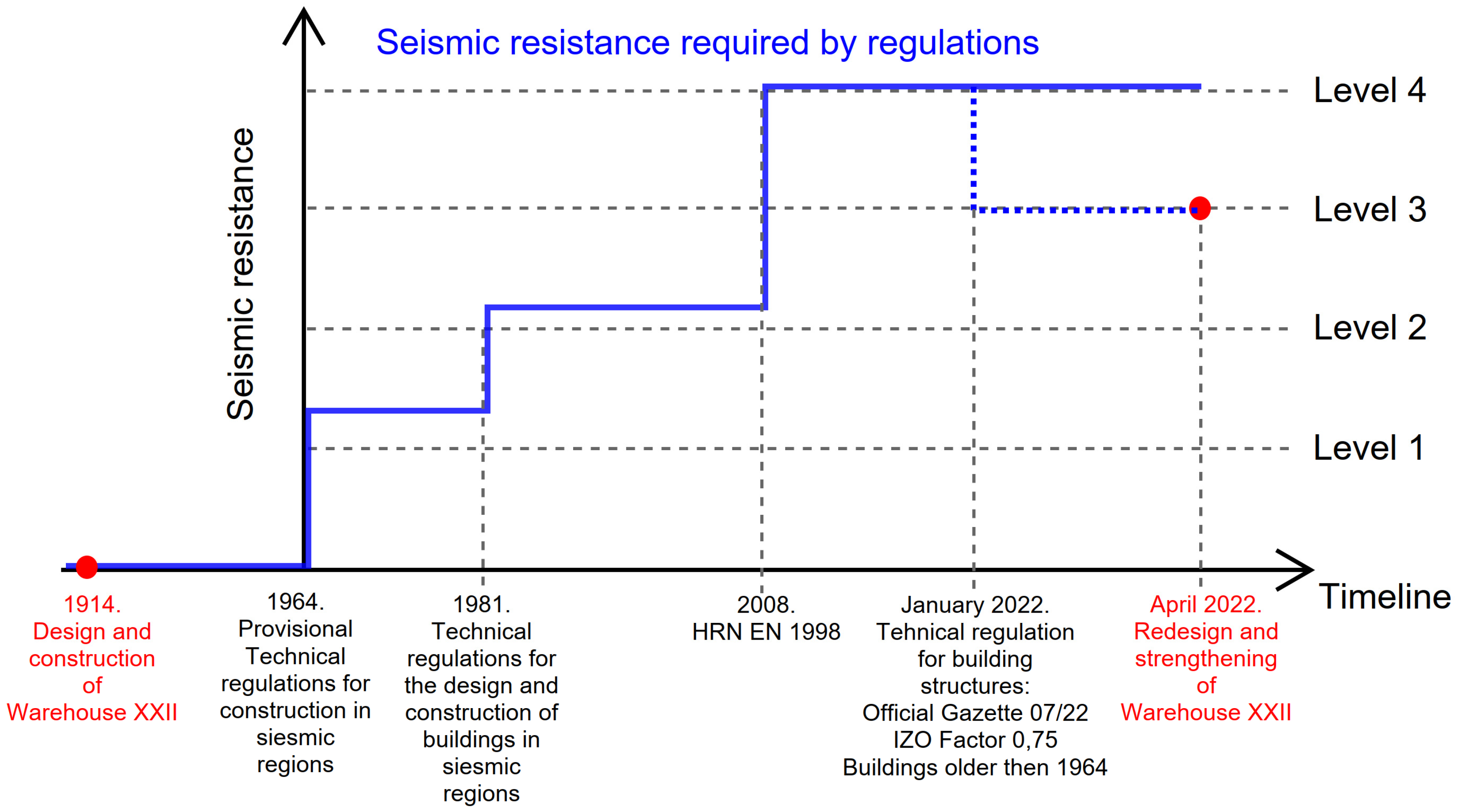
- IZO Factor 0.75 (according to TPGK 7/22) agR = 0.15 g
- Ground type: C—according to the geomechanical report
- Importance factor: γI = 1.0
- Damping: η = 5%
- Section 1: d = 3.1 mm.
- Section 2: d = 47.0 mm.
- Section 3: d = 24.4 mm.
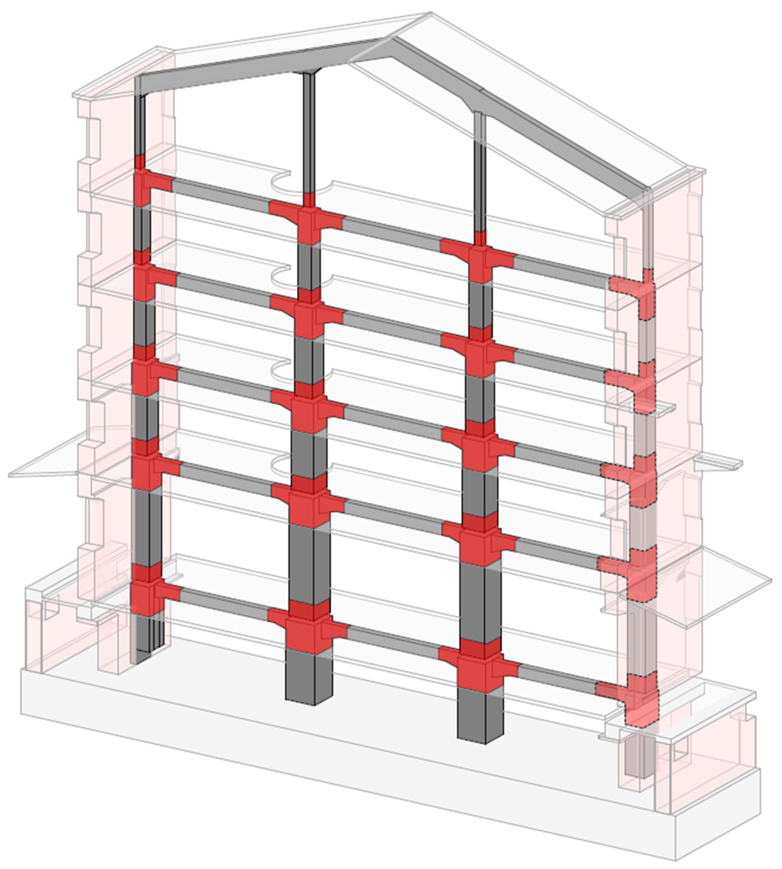
4.2.2. Construction of the RC Structure
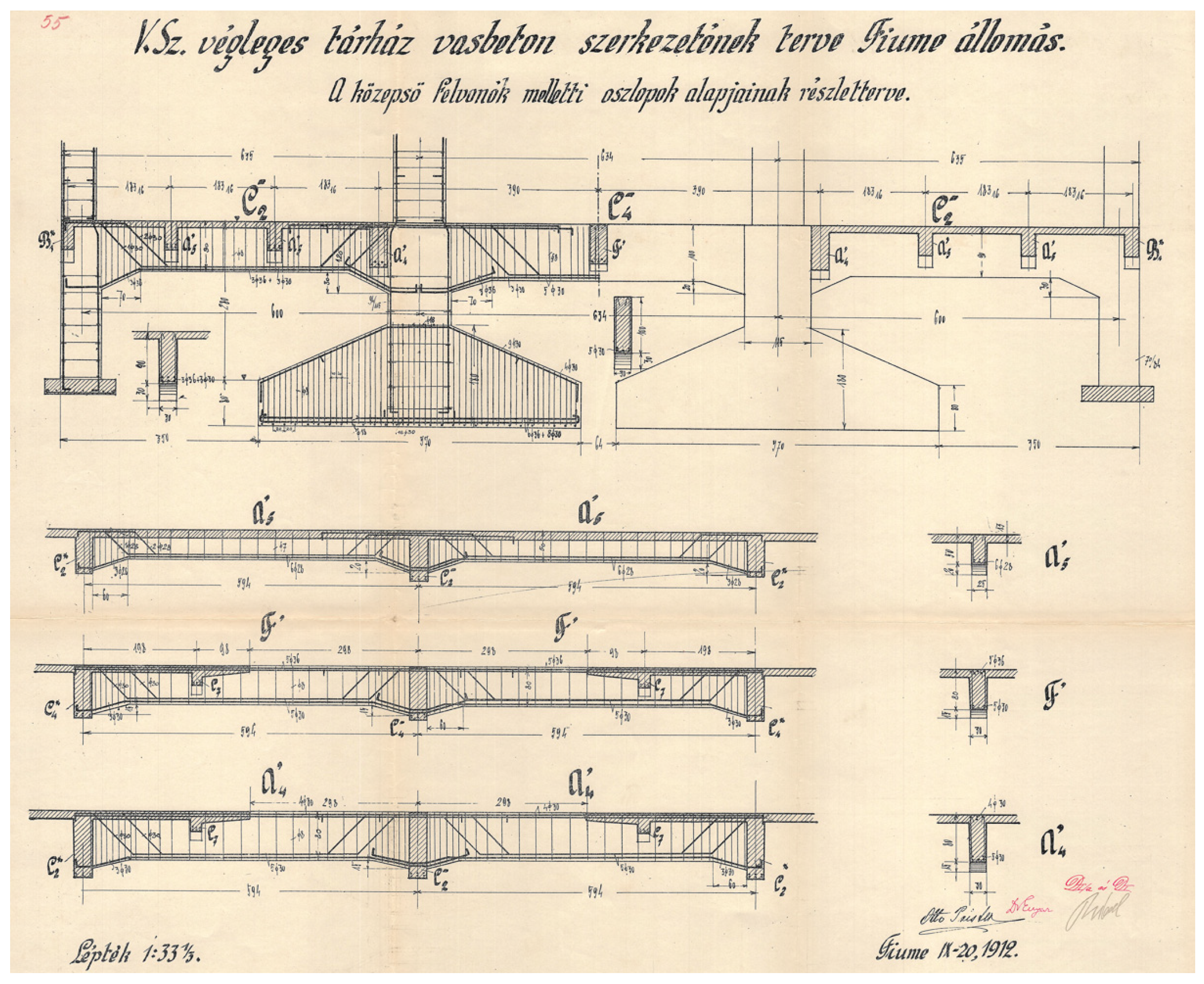
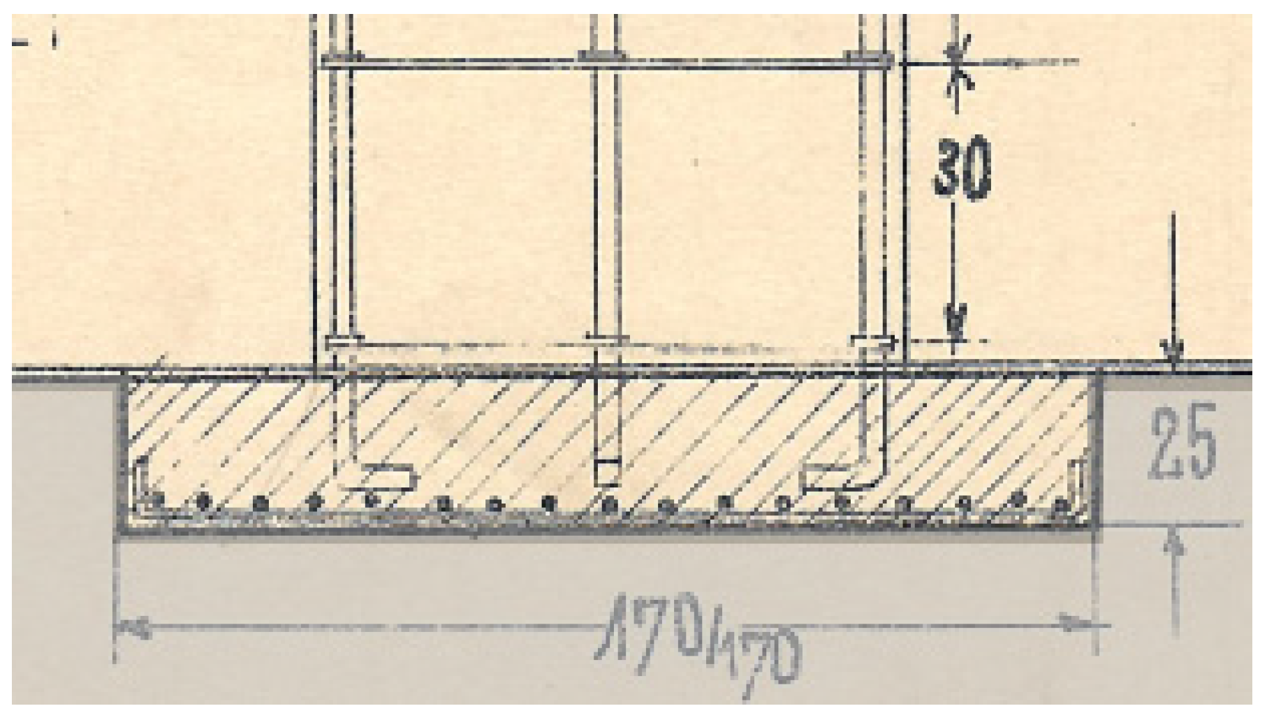
4.2.3. Construction of New Foundations
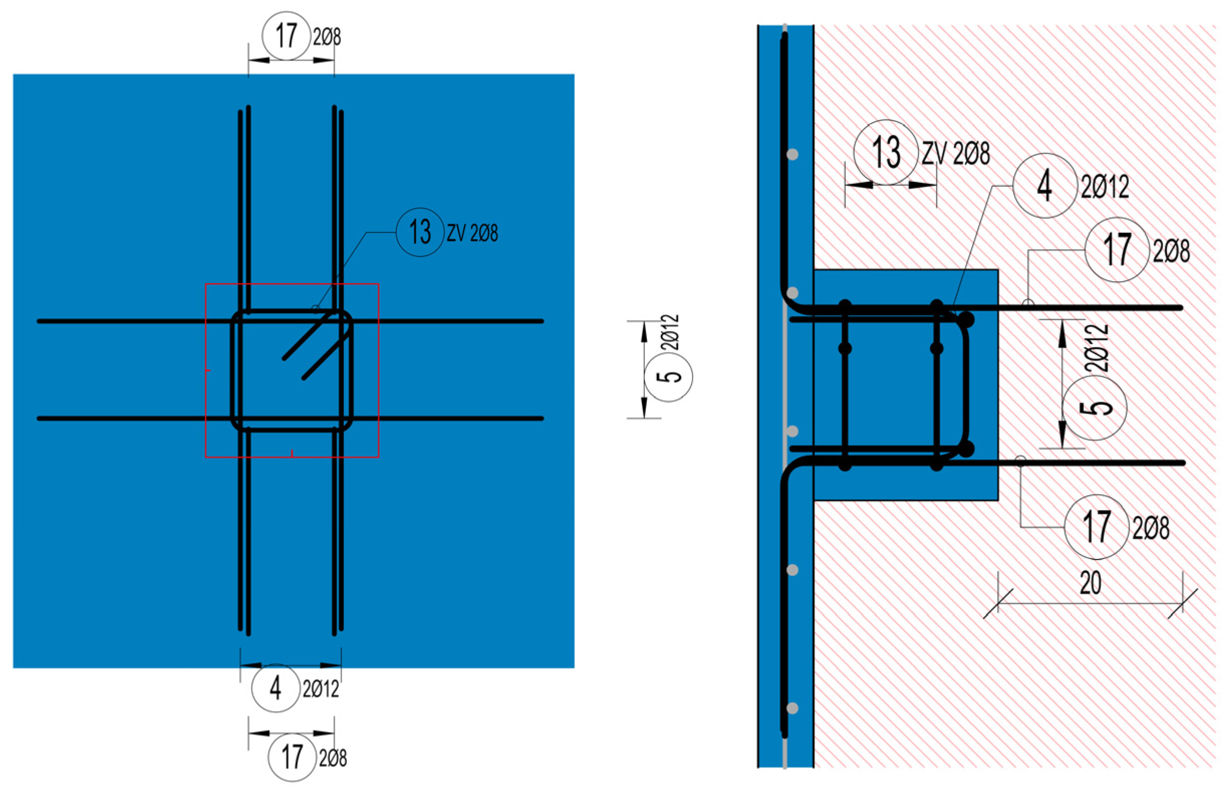
4.2.4. Strengthening of Masonry Façade Walls
5. Conclusions
Supplementary Materials
Author Contributions
Funding
Data Availability Statement
Acknowledgments
Conflicts of Interest
References
- Bilgin, H.; Shkodrani, N.; Hysenlliu, M.; Ozmen, H.B.; Isik, E.; Harirchian, E. Damage and performance evaluation of masonry buildings constructed in 1970s during the 2019 Albania earthquakes. Eng. Fail. Anal. 2022, 131, 105824. [Google Scholar] [CrossRef]
- Işık, E.; Avcil, F.; Harirchian, E.; Arkan, E.; Bilgin, H.; Özmen, H.B. Architectural Characteristics and Seismic Vulnerability Assessment of a Historical Masonry Minaret under Different Seismic Risks and Probabilities of Exceedance. Buildings 2022, 12, 1200. [Google Scholar] [CrossRef]
- Puncello, I.; Caprili, S. Seismic Assessment of Historical Masonry Buildings at Different Scale Levels: A Review. Appl. Sci. 2023, 13, 1941. [Google Scholar] [CrossRef]
- Yan, K.; Miyajima, M.; Kumsar, H.; Aydan, Ö.; Ulusay, R.; Tao, Z.; Chen, Y.; Wang, F. Preliminary report of field reconnaissance on the 6 February 2023 Kahramanmaras Earthquakes in Türkiye. Geoenvironmental Disasters 2024, 11, 1–24. [Google Scholar] [CrossRef]
- Ziraoui, A.; Kissi, B.; Aaya, H.; Mrabet, N.; Azdine, I. Seismic risk assessment, damage estimation, and strengthening of seismic construction standards in Morocco. J. Build. Pathol. Rehabil. 2024, 9, 1–15. [Google Scholar] [CrossRef]
- Mallardo, V.; Malvezzi, R.; Milani, E.; Milani, G. Seismic vulnerability of historical masonry buildings: A case study in Ferrara. Eng. Struct. 2008, 30, 2223–2241. [Google Scholar] [CrossRef]
- Stepinac, M.; Lourenço, P.B.; Atalić, J.; Kišiček, T.; Uroš, M.; Baniček, M.; Novak, M.Š. Damage classification of residential buildings in historical downtown after the ML5.5 earthquake in Zagreb, Croatia in 2020. Int. J. Disaster Risk Reduct. 2021, 56, 102140. [Google Scholar] [CrossRef]
- Hafner, I.; Lazarević, D.; Kišiček, T.; Stepinac, M. Post-Earthquake Assessment of a Historical Masonry Building after the Zagreb Earthquake–Case Study. Buildings 2022, 12, 323. [Google Scholar] [CrossRef]
- Atalić, J.; Novak, M.Š.; Uroš, M. Seismic risk for Croatia: Overview of research activities and present assessments with guidelines for the future. Građevinar 2019, 71, 923–947. [Google Scholar]
- World Bank Report: Croatia December 2020 Earthquake—Rapid Damage and Needs Assessment, 2020; Government of Croatia: Zagreb, Croatia, 2021.
- The Database of Usability Classification, Croatian Centre of Earthquake Engineering (HCPI—Hrvatski Centar za Potresno Inženjerstvo); Faculty of Civil Engineering, University of Zagreb: Zagreb, Croatia, 2020.
- Markušić, S.; Stanko, D.; Penava, D.; Trajber, D.; Šalić, R. Preliminary Observations on Historical Castle Trakošćan (Croatia) Performance under Recent ML ≥ 5.5 Earthquakes. Geosciences 2021, 11, 461. [Google Scholar] [CrossRef]
- Uroš, M.; Demšić, M.; Novak, M.; Atalić, J.; Baniček, M.; Rundek, R.J.; Duvnjak, I.; Košćak, J.; Pilipović, A.; Prevolnik, S. Damage Evaluation and Seismic Assessment of a Typical Historical Unreinforced Masonry Building in the Zagreb 2020 Earthquake: A Case Study—Part I. Buildings 2024, 14, 474. [Google Scholar] [CrossRef]
- Marinković, M.; Brzev, S.; Blagojević, N.; Miličević, I.; Zugic, Z.; Bursać, P. Performance of Masonry Buildings During the November 26, 2019 Albania Earthquake (M W 6.4) and December 29, 2020 Petrinja Earthquake (M W 6.4) 19th MASE SYMPOSIUM, MACEDONIAN ASSOCIATION OF STRUCTURAL ENGINEERS SE-7 502. Available online: http://mase.gf.ukim.edu.mk (accessed on 8 August 2024).
- Milić, M.; Stepinac, M.; Lulic, L.; Ivanisevic, N.; Matoric, I.; Sipos, B.C. Assessment and Rehabilitation of Culturally Protected Prince Rudolf Infantry Barracks in Zagreb after Major Earthquake. Buildings 2021, 11, 508. [Google Scholar] [CrossRef]
- Ivanov, M.L.; Chow, W.K. Structural damage observed in reinforced concrete buildings in Adiyaman during the 2023 Turkiye Kahramanmaras Earthquakes. Structures 2023, 58, 105578. [Google Scholar] [CrossRef]
- Vuran, E.; Serhatoğlu, C.; Timurağaoğlu, M.Ö.; Smyrou, E.; Bal, İ.E.; Livaoğlu, R. Damage observations of RC buildings from 2023 Kahramanmaraş earthquake sequence and discussion on the seismic code regulations. Bull. Earthq. Eng. 2024. [Google Scholar] [CrossRef]
- Kaplan, O.; Guney, Y.; Topcu, A.; Ozcelikors, Y. A rapid seismic safety assessment method for mid-rise reinforced concrete buildings. Bull. Earthq. Eng. 2018, 16, 889–915. [Google Scholar] [CrossRef]
- Jaiswal, K.; Hancilar, U.; Askan, A.; Erberik, M.A.; Cakti, E.; Rao, A.; Martins, L. A synopsis of rapid characterization and field-based performance assessment of RC structures from the M7.8 Kahramanmaras earthquake sequence. AGUFM 2023, 2023, U44A-02. Available online: https://ui.adsabs.harvard.edu/abs/2023AGUFM.U44A..02J/abstract (accessed on 8 August 2024).
- Abrahamczyk, L.; Penava, D.; Haweyou, M.; Anić, F.; Schultz, A.E.; Rautenberg, J. Assessment of damage to modern reinforced concrete buildings—Engineering analysis of the M6.4 Albania earthquake, 26th of Nov. 2019. In Proceedings of the COMPDYN Proceedings, Athens, Greece, 28–30 June 2021. [Google Scholar] [CrossRef]
- Anić, F.; Penava, D.; Abrahamczyk, L.; Sarhosis, V. On the mechanical behaviour of masonry infilled RC frames, with and without openings, subjected to simultaneous in-plane (IP) and out-of-plane (OoP) loading. Bull. Earthq. Eng. 2024, 22, 1775–1799. [Google Scholar] [CrossRef]
- Işık, E.; Avcil, F.; İzol, R.; Büyüksaraç, A.; Bilgin, H.; Harirchian, E.; Arkan, E. Field Reconnaissance and Earthquake Vulnerability of the RC Buildings in Adıyaman during 2023 Türkiye Earthquakes. Appl. Sci. 2024, 14, 2860. [Google Scholar] [CrossRef]
- Işık, E.; Avcil, F.; Hadzima-Nyarko, M.; İzol, R.; Büyüksaraç, A.; Arkan, E.; Radu, D.; Özcan, Z. Seismic Performance and Failure Mechanisms of Reinforced Concrete Structures Subject to the Earthquakes in Türkiye. Sustainability 2024, 16, 6473. [Google Scholar] [CrossRef]
- Işık, E.; Hadzima-Nyarko, M.; Radu, D.; Bulajić, B. Study on Effectiveness of Regional Risk Prioritisation in Reinforced Concrete Structures after Earthquakes. Appl. Sci. 2024, 14, 6992. [Google Scholar] [CrossRef]
- Stepinac, M.; Skokandić, D.; Ožić, K.; Zidar, M.; Vajdić, M. Condition Assessment and Seismic Upgrading Strategy of RC Structures—A Case Study of a Public Institution in Croatia. Buildings 2022, 12, 1489. [Google Scholar] [CrossRef]
- Uroš, M.; Demšić, M.; Baniček, M.; Pilipović, A. Seismic Retrofitting of Dual Structural Systems—A Case Study of an Educational Building in Croatia. Buildings 2023, 13, 292. [Google Scholar] [CrossRef]
- Ortega, J.; Vasconcelos, G.; Rodrigues, H.; Correia, M. A vulnerability index formulation for the seismic vulnerability assessment of vernacular architecture. Eng. Struct. 2019, 197, 109381. [Google Scholar] [CrossRef]
- Khattak, N.; Derakhshan, H.; Ferreira, T.M.; Perera, N.J.; Thambiratnam, D.P. Seismic vulnerability assessment of pre-1945 unreinforced masonry buildings located in Queensland, Australia, using an index-based approach. Structures 2024, 67, 106900. [Google Scholar] [CrossRef]
- Hung, C.C.; Agrawal, S.; Hsiao, H.J. Rehabilitation of seismically-damaged RC beam-column joints with UHPC and high-strength steel mesh reinforcement. J. Build. Eng. 2024, 84, 108667. [Google Scholar] [CrossRef]
- Zapris, A.G.; Kytinou, V.K.; Gribniak, V.; Chalioris, C.E. Novel approach for strengthening T-beams deficient in shear with near-surface mounted CFRP ropes in form of closed stirrups. Dev. Built Environ. 2024, 18, 100394. [Google Scholar] [CrossRef]
- Mosoarca, M.; Victor, G. Structural safety of historical buildings made of reinforced concrete, from Banat region—Romania. J. Cult. Herit. 2013, 14, e29–e34. [Google Scholar] [CrossRef]
- Redondo, G.P.; Franco, G.; Georgiou, A.; Ioannou, I.; Lubelli, B.; Musso, S.F.; Naldini, S.; Nunes, C.; Vecchiattini, R. State of conservation of concrete heritage buildings: A european screening. Infrastructures 2021, 6, 109. [Google Scholar] [CrossRef]
- Marcos, I.; San-José, J.T.; Garmendia, L.; Santamaría, A.; Manso, J.M. Central lessons from the historical analysis of 24 reinforced-concrete structures in northern Spain. J. Cult. Herit. 2016, 20, 649–659. [Google Scholar] [CrossRef]
- Stochino, F.; Fadda, M.L.; Mistretta, F. Low cost condition assessment method for existing RC bridges. Eng. Fail. Anal. 2018, 86, 56–71. [Google Scholar] [CrossRef]
- Gams, M.; Starešinič, G.; Isaković, T. Full-scale shaking table test of a reinforced concrete precast building with horizontal concrete cladding panels and a numerical simulation. J. Build. Eng. 2022, 55, 104707. [Google Scholar] [CrossRef]
- Triantafillou, T.C.; Papanicolaou, C.G. Shear strengthening of reinforced concrete members with textile reinforced mortar (TRM) jackets. Mater. Struct./Mater. Constr. 2006, 39, 93–103. [Google Scholar] [CrossRef]
- Thermou, G.E.; Elnashai, A.S. Seismic retrofit schemes for RC structures and local-global consequences. Prog. Struct. Eng. Mater. 2006, 8, 1–15. [Google Scholar] [CrossRef]
- Thermou, G.E.; Pantazopoulou, S.J.; Elnashai, A.S. Flexural Behavior of Brittle RC Members Rehabilitated with Concrete Jacketing. J. Struct. Eng. 2007, 133, 1373–1384. [Google Scholar] [CrossRef]
- Karayannis, C.G.; Chalioris, C.E.; Sirkelis, G.M. Local retrofit of exterior RC beam-column joints using thin RC jackets—An experimental study. Earthq. Eng. Struct. Dyn. 2008, 37, 727–746. [Google Scholar] [CrossRef]
- Chalioris, C.E.; Thermou, G.E.; Pantazopoulou, S.J. Behaviour of rehabilitated RC beams with self-compacting concrete jacketing—Analytical model and test results. Constr. Build. Mater. 2014, 55, 257–273. [Google Scholar] [CrossRef]
- Salaman, A.; Stepinac, M.; Matorić, I.; Klasić, M. Post-Earthquake Condition Assessment and Seismic Upgrading Strategies for a Heritage-Protected School in Petrinja, Croatia. Buildings 2022, 12, 2263. [Google Scholar] [CrossRef]
- Law on the Reconstruction of Earthquake-Damaged Buildings in the City of Zagreb, Krapina-Zagorje County and Zagreb County (NN 102/2020). Available online: https://narodne-novine.nn.hr/clanci/sluzbeni/2020_09_102_1915.html (accessed on 3 April 2024).
- Law on Reconstruction of Earthquake-Damaged Buildings in the City of Zagreb, Krapina-Zagorje County, Zagreb County, Sisak-Moslavina County and Karlovac County (NN 102/2020, 10/21). Available online: https://www.zakon.hr/z/2656/Zakon-o-obnovi-zgrada-o%C5%A1te%C4%87enih-potresom-na-podru%C4%8Dju-Grada-Zagreba%2C-Krapinsko-zagorske-%C5%BEupanije%2C-Zagreba%C4%8Dke-%C5%BEupanije%2C-Sisa%C4%8Dko-moslava%C4%8Dke-%C5%BEupanije-i-Karlova%C4%8Dke-%C5%BEupani (accessed on 3 April 2024).
- TEHNIČKI PROPIS O IZMJENAMA I DOPUNAMA TEHNIČKOG PROPISA ZA GRAĐEVINSKE KONSTRUKCIJE, NN 7/2022. Available online: https://narodne-novine.nn.hr/clanci/sluzbeni/2022_01_7_72.html (accessed on 3 April 2024).
- HRN EN 1998-3:2011; Eurocode 8: Design of Structures for Earthquake Resistance—Part 3: Assessment and Retrofitting of Buildings (EN 1998-3:2005+AC:2010). National Standards Authority of Ireland, 2005. Available online: https://www.phd.eng.br/wp-content/uploads/2014/07/en.1998.3.2005.pdf (accessed on 12 September 2024).
- Hafner, I.; Kišiček, T.; Gams, M. Review of Methods for Seismic Strengthening of Masonry Piers and Walls. Buildings 2023, 13, 1524. [Google Scholar] [CrossRef]
- Berkes, J. Izgradnja Riječke luke od 1868. do 1918. Godine, Riječka Luka, Povijest, Izgradnja, Promet, Katalog Izložbe; Muzej grada Rijeke, 2001; pp. 133–164. [Google Scholar]
- Palinic, N. Early reinforced-concrete structures in Rijeka Port. Gradevinar 2009, 61, 435–444. [Google Scholar]
- Konzervatorski elaborat Skladište 22 u sklopu kompleksa Metropolis na k.č. 3344 k.o. Stari grad u Rijeci, ASK Atelier d.o.o., Zagreb, veljača 2023.
- Available online: https://forum.lokalpatrioti-rijeka.com/viewtopic.php?p=96957 (accessed on 4 March 2024).
- Available online: https://maps.arcanum.com/en/synchron/firstsurvey-croatia/ (accessed on 4 March 2024).
- Dlubal RFEM 5. Available online: https://www.dlubal.com/en/products/older-products/rfem-5/what-is-rfem-5?srsltid=AfmBOop_2XgwI2jW6Kf_5RITQ1JuvIG4YJWUNicMaZkhmAaVeLf0V0O8 (accessed on 24 February 2024).
- HRN EN1998:1; Design of Structures for Earthquake Resistance—Part 1: General Rules, Seismic Actions and Rules for Buildings (EN 1998-1:2004+AC:2009).
- EN 12504-1:2019; Testing Concrete in Structures—Part 1: Cored Specimens—Taking; Examining and Testing in Compression. 2019.
- EN 13791:2019; Assessment of In-Situ Compressive Strength in Structures and Precast Concrete Component. 2019.
- Ortega, J.; Stepinac, M.; Lulić, L.; García, M.N.; Saloustros, S.; Aranha, C.; Greco, F. Correlation between sonic pulse velocity and flat-jack tests for the estimation of the elastic properties of unreinforced brick masonry: Case studies from Croatia. Case Stud. Constr. Mater. 2023, 19, e02467. [Google Scholar] [CrossRef]
- Lulić, L.; Stepinac, M.; Bartolac, M.; Lourenço, P.B. Review of the flat-jack method and lessons from extensive post-earthquake research campaign in Croatia. Constr. Build. Mater. 2023, 384, 131407. [Google Scholar] [CrossRef]
- Krolo, J.; Damjanović, D.; Duvnjak, I.; Smrkić, M.F.; Bartolac, M.; Košćak, J. Methods for determining mechanical properties of walls. Gradjevinar 2021, 73, 127–140. [Google Scholar] [CrossRef]
- FRILO Software GmbH. Available online: https://www.frilo.eu/ (accessed on 24 February 2024).


| WAREHOUSE XXII | SECTION 1 | SECTION 2 | SECTION 3 | |||
|---|---|---|---|---|---|---|
| Walls in X Direction | Walls in Y Direction | Walls in X Direction | Walls in Y Direction | Walls in X Direction | Walls in Y Direction | |
| Existing warehouse | 5.72% | 1.32% | 2.86% | 0.00% | 5.64% | 1.04% |
| Strengthen warehouse | 6.85% | 2.60% | 3.08% | 1.22% | 6.58% | 2.10% |
| Floor | Structural Element | Corrosion Grade of Reinforcement Cu/CuSO4 > −200 Low −200 < Cu/CuSO4 < −350 Medium | ||
|---|---|---|---|---|
| 100—basement | column | low | to | medium |
| 200—ground floor | column | low | ||
| 300—first floor—connecting building | column | low | ||
| 400—second floor | column | low | ||
| 500—third floor—connecting building | column | low | ||
| 600—fourth floor | column | medium | ||
| CONCRETE ELEMENTS | |||||||
|---|---|---|---|---|---|---|---|
| Elements: | Beams and Slabs | Columns | Foundation Slab | New Structure | |||
| Compressive strength | C20/25 | C20/25 | C30/37 | C30/37 | |||
| Elastic modulus E (MPa) | 30,000 | 30,000 | 33,000 | 33,000 | |||
| Shear modulus G (MPa) | 12,500 | 12,500 | 13,750 | 13,750 | |||
| Poisson’s ratio | 0.2 | 0.2 | 0.2 | 0.2 | |||
| Type of modeled element | Isotropic linear elastic surface | Isotropic linear elastic surface | Isotropic linear elastic surface | Isotropic linear elastic surface | |||
| MASONRY WALLS | |||||||
| Elements: | Existing masonry wall | Shotcrete part of wall | Strengthened masonry wall | ||||
| Compressive strength of brick fb (MPa) | 12 | -- | 12 | ||||
| Compressive strength mortar fm (MPa) | 9 | -- | 9 | ||||
| Compressive strength masonry wall fk (MPa) or shotcrete fck (MPa) | 6.05 | 25 | -- | ||||
| Masonry wall weight (kN/m3) | 18 | 25 | 18.7 | ||||
| Elastic modulus E (MPa) | 6054 | 31,000 | 13,690 | ||||
| Shear modulus G (MPa) | 2421 | 12,917 | 5476 | ||||
| Poisson’s ratio | 0.25 | 0.20 | 0.25 | ||||
| Type of modeled element | Material model: Orthotropic Elastic 2D Surface stiffness: Orthotropic | Material model: Orthotropic Elastic 2D Surface stiffness: Orthotropic | |||||
| NEW STRUCTURE | EXISTING STRUCTURE | ||||||||
|---|---|---|---|---|---|---|---|---|---|
| Storey | Storey Height | Relative Displacement | Limitation of Interstorey Drift dr,x/n ≤ 0.005 h | Relative Displacement | Limitation of Interstorey Drift dr,x/n ≤ 0.005 h | ||||
| hetaže | dx,e | dx,e | |||||||
| [mm] | [mm] | [mm] | [mm] | [%] | [mm] | [mm] | [mm] | [%] | |
| FLOOR 600 | 3150 | 4.7 | 2.8 | 15.8 | 17.8% | 196.0 | 19.9 | 15.8 | 126.3% |
| FLOOR 500 | 3150 | 1.9 | 0.4 | 15.8 | 2.5% | 176.1 | 19.3 | 15.8 | 122.5% |
| FLOOR 400 | 3150 | 1.5 | 0.4 | 15.8 | 2.5% | 156.8 | 24.1 | 15.8 | 153.0% |
| FLOOR 300 | 3150 | 1.1 | 0.3 | 15.8 | 1.9% | 132.7 | 31.0 | 15.8 | 196.8% |
| FLOOR 200 | 4200 | 0.8 | 0.2 | 21.0 | 1.0% | 101.7 | 57.3 | 21.0 | 272.9% |
| FLOOR 100 | 2800 | 0.6 | 0.6 | 14.0 | 4.3% | 44.4 | 44.4 | 14.0 | 317.1% |
| FOUNDATION LEVEL | 0 | 0.0 | 0.0 | 0.0 | 0.0 | 0.0 | 0.0 | 0.0 | 0.0 |
Disclaimer/Publisher’s Note: The statements, opinions and data contained in all publications are solely those of the individual author(s) and contributor(s) and not of MDPI and/or the editor(s). MDPI and/or the editor(s) disclaim responsibility for any injury to people or property resulting from any ideas, methods, instructions or products referred to in the content. |
© 2024 by the authors. Licensee MDPI, Basel, Switzerland. This article is an open access article distributed under the terms and conditions of the Creative Commons Attribution (CC BY) license (https://creativecommons.org/licenses/by/4.0/).
Share and Cite
Bošnjak, B.; Pekas, N.; Stepinac, M. Seismic Upgrading of the Heritage-Protected Reinforced Concrete Warehouse in Rijeka, Croatia. Buildings 2024, 14, 2912. https://doi.org/10.3390/buildings14092912
Bošnjak B, Pekas N, Stepinac M. Seismic Upgrading of the Heritage-Protected Reinforced Concrete Warehouse in Rijeka, Croatia. Buildings. 2024; 14(9):2912. https://doi.org/10.3390/buildings14092912
Chicago/Turabian StyleBošnjak, Berislav, Nikola Pekas, and Mislav Stepinac. 2024. "Seismic Upgrading of the Heritage-Protected Reinforced Concrete Warehouse in Rijeka, Croatia" Buildings 14, no. 9: 2912. https://doi.org/10.3390/buildings14092912
APA StyleBošnjak, B., Pekas, N., & Stepinac, M. (2024). Seismic Upgrading of the Heritage-Protected Reinforced Concrete Warehouse in Rijeka, Croatia. Buildings, 14(9), 2912. https://doi.org/10.3390/buildings14092912