Article

Energy Flexibility Strategies for Buildings in Hot Climates: A Case Study for Dubai

by
Ali Saberi-Derakhtenjani
,
Juan David Barbosa
and
Edwin Rodriguez-Ubinas
*
Dubai Electricity and Water Authority, DEWA R&D Centre, Dubai P.O. Box 564, United Arab Emirates
*
Author to whom correspondence should be addressed.
Buildings 2024, 14(9), 3008; https://doi.org/10.3390/buildings14093008
Submission received: 29 August 2024 / Revised: 11 September 2024 / Accepted: 16 September 2024 / Published: 22 September 2024
(This article belongs to the Special Issue Flexible Interaction between Buildings and Power Grid)

Abstract

:
This paper presents a case study of energy flexibility strategies for a building located in the hot climate of Dubai, a type of climate in which energy flexibility has been under-researched. Energy flexibility is changing the routine-consumption profile and deviating from the normal operation of the building by the users to manage the variability in the load profile and cost of electricity. The three flexibility strategies being considered are based on the modulation of the indoor air temperature setpoint profile while considering different marginal costs for electricity. The main objective is to quantify the energy storage flexibility of each strategy and evaluate its impact on the system ramping and load factor. The study was carried out utilizing a grey-box, resistance–capacitance model of the building, which was validated against experimental measurements. This study is the first to use the following five indicators simultaneously: load factor, system ramping, storage capacity, peak-period demand reduction, and cost savings. Combining these indicators helps building facility managers and distribution system operators (DSOs) better understand the implications of implementing a specific flexibility strategy in a building or a group of buildings. When comparing the indicators of each strategy with each other, it was observed that depending on the amplitude of the change in the electricity cost signal during the peak period, a significant cost reduction of more than 25% could be achieved through the implementation of specific flexibility strategies compared with the normal baseline operating condition.

1. Introduction

The building sector consumes around 40% of the world’s primary energy and is responsible for nearly 39% of global carbon emissions [1]. Thus, decarbonizing the building sector and maintaining the operational reliability of built infrastructure under increasingly severe and extreme conditions is vital for the future. As climate change leads to more frequent extreme weather events, the importance of energy efficiency, flexibility, and resilience in buildings and power grids becomes increasingly clear. Energy-resilient and flexible facilities can maintain critical services, such as lighting, heating, and cooling, even during electricity supply disruptions. This helps safeguard occupants from harm while ensuring their comfort and well-being. Energy-flexible buildings can adjust their energy consumption and generation in response to local climate conditions, user demands, and grid requirements. By lowering peak demand and offering ancillary services, they enhance grid reliability.
The shift toward flexible and resilient buildings is increasingly aligned with the rising interest in fully electric buildings, which contribute to sustainability goals, enhance energy efficiency, support renewable energy integration, utilize technological innovations, and adhere to regulatory standards. Fully electric buildings, however, heighten the reliance on the capacity and reliability of power grids. As a result, energy flexibility through demand-side management (DSM) and energy storage technologies is becoming increasingly vital to balance the supply and demand of electricity in buildings. This issue is particularly important given the intermittent nature of the rising renewable energy generation from solar photovoltaics (PVs) and the growing variability in electricity demand from buildings and EV charging.
The IEA Annex 67 [2] was among the earliest research initiatives, starting in 2015, to pioneer the development and formulation of the concept of energy-flexible buildings. More recently, several international collaborations and research efforts including IEA Annex 82 [3], Annex 81 [4], and the Grid-Interactive Efficient Buildings (GEB) roadmap by the U.S. DOE [5], have been working to advance this concept further. Energy flexibility is typically defined as the ability to shift, increase, or reduce power or energy consumption in response to external signals (such as cost signals) without compromising indoor comfort over a given time frame. Under the research activities of the IEA EBC Annex 67, the following unified definition of building energy flexibility was developed:
“The ability of a building to adapt/manage its short-term (a few hours or a couple of days) energy demand and generation according to local climate conditions, user needs, and energy network requirements without jeopardizing the technical capabilities of the operating systems in the building and the comfort of its occupants. Energy Flexibility of buildings will thus allow for DSM/load control and thereby DR based on the requirements of the surrounding energy grids.”
[6]
Therefore, energy-flexible buildings (EFBs) are energy-efficient buildings that can manage their energy demand through various components, including smart building management systems (BMSs), adjustable HVAC systems, thermal energy storage, renewables, batteries, electric vehicles, thermal mass, and plug-in load shifting. Characterizing the energy flexibility of buildings is generally complex, as it encompasses multiple factors, including the interaction of passive and active heat transfers, electrical phenomena, occupants, and the building structure itself. Additionally, it is highly influenced by boundary conditions and the methods used for assessment. As a result, the study of energy flexibility in buildings has become a topic of great interest in current scientific research [7,8,9,10,11,12,13].
Recent research on building energy flexibility has focused on developing frameworks and indicators to quantify and evaluate this emerging strategy. Awan et al. [14] proposed a method to aggregate energy flexibility indicators into a single dimensionless value, demonstrating its effectiveness through case studies. Morovat et al. [15] assessed key performance indicators for energy flexibility in electrically heated school buildings, finding significant potential, especially in colder weather. Li et al. [7] addressed ten critical questions concerning energy flexibility in buildings, covering technological, social, commercial, and regulatory aspects. They emphasized the importance of balancing stakeholder engagement and technology deployment, as well as the crucial roles of standardization, regulation, and policy in advancing the implementation of energy-flexible buildings. Kheiri et al. [16] proposed a model integrating air source heat pumps (ASHPs) into home energy management systems, demonstrating potential for reduced electricity consumption while maintaining comfort. Rehman and Hasan [17] compared old and new buildings in Finland, finding that older buildings offer greater flexibility and cost savings, while newer buildings show better resilience during power outages. In another study, these researchers [18] incorporate photovoltaic systems, enhancing both flexibility and resilience in both building types. On the other hand, Liu et al. [19] investigated energy flexibility in hot summer and cold winter zones, proposing a system with energy storage that improves cost-effectiveness and reduces carbon emissions.
It is observed that most of the literature on energy-flexible buildings focuses on heating-dominated climates. Some examples include works by [20,21,22,23,24]. Therefore, studies on this topic in cooling-dominated, hot climates are scarce. Lu et al. [25] conducted a simulation study to assess the energy flexibility of the cooling system in a nearly zero-energy office building. Their parametric analysis showed that thermal mass flexibility is primarily influenced by the structural thermal capacity, internal gains, and the type of cooling system. However, the level of insulation in the external walls had a minimal impact on flexibility. Afroz et al. [26] applied a flexibility function-based method to examine the flexible behavior of an office building in response to fluctuating electricity price signals. Their findings indicated that when electricity prices are very low, the cooling setpoint moves closer to the lower comfort limit, leading to a significant rise in cooling demand. Triolo et al. [27] proposed a methodology for estimating the aggregate cooling demand response of co-located buildings to an increase in the thermostat temperature set point using empirically estimated building-level demand reductions in a subset of these buildings. On the highest demand day of 2020, they reported that the predicted demand reduction could provide services equivalent to those provided by a lithium-ion battery with $4.6–$8.0 million installation cost and a storage capacity of 35.6–52.6 MWh. Mugnini et al. [28] assessed and compared the operational energy flexibility of various residential space cooling technologies, including all-air systems and fan-coil units, both with and without thermal energy storage, as well as hydronic systems, using dynamic simulation models. Their findings indicated that split systems with on–off regulation offer the least flexibility, requiring up to 10 h of precooling to lower electricity consumption during peak periods. In contrast, fan-coil units with thermal energy storage can employ peak shaving strategies without significantly affecting indoor air temperatures and with only moderate increases in electricity consumption before the demand response event (up to 23%) and reductions afterward (up to 16%). Additionally, they noted that as the thermal inertia of the cooling system increases—from ceiling panels to concrete ceilings—the indoor environment is less impacted during demand response events. However, the anticipated overconsumption of the heat pump rises sharply, from 67% for ceiling panels to 116% for concrete ceilings.
The present study aims to contribute to the development of strategies and methodologies for buildings located in cooling-dominated, hot climates. It focuses on flexibility activation strategies based on the building’s thermal mass and includes an evaluation of the impact of such strategies on the overall load factor and ramping of the building’s cooling load. There are several inherent differences between hot and cold climates when designing energy flexibility strategies. The main difference is the strategy implementation time due to their different peak periods. Typically, there are early morning and evening peaks in cold climates during a cold winter day. In hot climates, during a hot summer day, the peak consumption period normally starts around noon and continues for some hours after.
As noted earlier, the development of comprehensive and broadly applicable indicators for evaluating energy flexibility in buildings is a complex endeavor due to the multidimensional aspects of flexibility, the dependence on unique building characteristics, the climate, the lack of standardized methodologies, occupant behavior, and grid requirements. Therefore, many indicators have been developed and used in previous studies to quantify different aspects of energy flexibility for buildings or systems [23,24,25]. While some flexibility indicators share common characteristics, the choice of indicators depends on several factors, including the significance of energy consumption versus power consumption, climatic conditions, electricity cost/tariff structure, etc. Most existing indicators in the literature quantify energy/power shifts and prebound/rebound effects [11,14,29,30]. Very few studies with indicators have described the impact of flexibility strategies on system stability. To address this gap, the present study implemented two indicators to evaluate the effects of flexibility strategies on system stability, namely, the load factor (the average load divided by the maximum load) and system ramping (load change from one unit of time to another), in addition to the following three more widely employed indicators: storage capacity, peak-period energy demand reduction, and cost savings. Therefore, when a building is asked to participate in a flexibility event and alter its energy behavior from baseline, the potential impact of this change on the load factor and ramping effort of the system is also considered, along with the storage and load-shifting capacity.
This study is one of the first to use these five indicators from different fields simultaneously, presenting a comprehensive picture of the case study’s energy flexibility. Combining these indicators helps building facility managers and distribution system operators (DSOs) better understand the implications of implementing a specific flexibility strategy in a building or a group of buildings.

1.1. Energy Flexibility Context for Hot Climates and Dubai

The swift growth in electricity demand in Dubai requires investments to enhance the Emirate’s energy network. In 2023, the electricity demand in Dubai reached 56.5 TWh, representing a 6.3% increase from the previous year’s demand of 53.2 TWh [31]. Therefore, to meet the steadily rising energy demand and associated carbon emissions, Dubai is undertaking an ambitious initiative to boost the share of renewables in its energy generation mix. The Dubai Clean Energy Strategy aims to provide 25% of Dubai’s power output from clean energy by 2030 and 100% by 2050 [32]. The Dubai Electricity and Water Authority initiatives, such as the Mohammed bin Rashid Al Maktoum (MBR) Solar Park and Shams Dubai [33] distributed generation programs, have significantly increased solar energy production. The MBR solar park is the largest single-site solar park in the world based on the Independent Power Producer (IPP) model, with a planned production capacity of 5000 MW by 2030 [34]. However, solar power is inherently variable, which can impact the stability of the energy system, especially when it represents a substantial share of total generation, as outlined in Dubai’s future clean energy strategy. The energy transition toward renewable sources is a common objective in other countries with hot climates in the region and around the world, and energy-flexible buildings can contribute to this transition, adding a quick response to the grid’s dynamic needs. Therefore, it is crucial to evaluate the implementation feasibility and ability to support the stability and decarbonization of the power grid in the region. This is one of the first studies of energy-flexible buildings in a hot desert climate.

1.2. Contributions of This Research

This work aims to study the application of precooling control strategies in a commercial building in an extremely hot climate to achieve energy flexibility. The indicators are presented and utilized to evaluate the potential energy flexibility of the building. Moreover, the impacts of flexibility strategies, the thermal performance of the building, and weather conditions on the load factor and the ramping requirements of the building cooling load are analyzed and their interactions are explored. Finally, cost analysis for different strategies is performed, and cost-saving opportunities are identified and compared with the reference baseline operation of the building. This paper makes the following main contributions:
(1)
A data-driven grey-box modelling methodology is presented as a tool to evaluate building energy flexibility.
(2)
Energy flexibility indicators are proposed to quantify energy flexibility from the perspective of thermal energy storage, load shifting, and reduction, and to assess the impact of implementing flexibility strategies on the overall load factor and system ramping of the building cooling load.
(3)
Cost analysis of implemented energy flexibility strategies and identification of cost savings/increases compared with the baseline operation of the building.
Overall, this study combines indicators from different fields in a novel way to present a more comprehensive view on how flexibility strategy implementation can affect the system. Therefore, the users and even the DSO can have a much more comprehensive understating of the consequences, benefits, and limitations of an implemented flexibility strategy.

2. Methods

This section presents the methodology employed to quantify and evaluate the thermal energy flexibility of the building. An overview of the case study is provided first, followed by a description of the modelling process through a data-driven grey box approach. The energy flexibility strategies are then described, and the five key performance indicators (KPIs) utilized are presented.

2.1. Description of the Case Study: Electrically Cooled Commercial Building

The case study involves a two-story, LEED Platinum-certified commercial building (Figure 1) in Dubai, that has been operating since the last quarter of 2018. The building has a total floor area of approximately 4000 m² and is composed of the following two main sections: an office space with a common area (≈2300 m²) and a laboratory/workshop area (≈1700 m2). Operation schedules in the building follow a regular 8 am to 5 pm schedule on weekdays and an unoccupied schedule on weekends.

2.1.1. Construction and Facades

The office volume is designed with extensive glazing, featuring double-pane windows on the east, west, and north facades. The east and west facades are shaded by colored semi-transparent building-integrated photovoltaic (BIPV) fins. The central atrium, which is equipped with a skylight, ensures natural light in the core of the building, reducing the need for artificial lighting during the day. The construction utilizes concrete slabs and columns for the main structure, which contains high thermal mass.

2.1.2. Cooling System

The facility has a 300-ton refrigeration (TR) chiller plant, comprising of two 150 TR air-cooled chillers and two primary-only chilled water pumps, each equipped with variable frequency drives (VFDs) to adjust the flow according to the building demand. The cooling supply is quantified using an energy meter located at the plant’s output, which monitors both the chilled water flow and the temperature differential between the supply and return pipes. The chiller plant usually operates with a single chiller, with the second chiller activated only during peak summer demand. On the air distribution side, both the office and workshop volumes have a dedicated fresh air handling unit (FAHU) that feeds into an air handling unit (AHU), which then distributes the air to the user’s open space through a series of variable air volume units (VAVs). Additional fan coil units (FCUs) are installed in private offices and meeting rooms that do not have access to the VAV air supply.

2.1.3. Controls

The building is controlled with a building management system (BMS) that defines most indoor variables, such as temperature setpoints and light controls. Lights operate under occupancy schedules, while a setpoint and setback temperature schedule can be set at the space thermostat. However, the BMS can centrally override any user inputs when needed. For the experimental purposes of this project, set points were centrally controlled and monitored through the BMS. Only the office area set points were modulated to test its flexibility. At the same time, the workshop conditions were kept steady, given their need to maintain precise indoor conditions.

2.2. Data-Driven Grey-Box Model

Building energy models are typically classified into white-box, black-box, and grey-box models. White-box models employ physical principles to simulate heating and cooling demand, black-box models utilize data-driven approaches, and grey-box models combine physical insights with real data. Data-driven, grey-box, resistance–capacitance (RC) models have proven to be effective and practical for analyzing control strategies in buildings ([35,36]). Model calibration is also much less complicated than the physical white-box models due to the reduced number of parameters involved. This paper utilizes the lumped-parameter, explicit finite-difference method for thermal modeling, which conducts an energy balance on the control volume. This approach is based on the electric network analogy. Considering the time interval “p” and time step “Δt,” the general form of the explicit finite-difference model for nodes with a lumped thermal capacitance can be expressed as follows [37]:
T i , p + 1 = T i , p + Δ t C i ( Q i + j T j , p T i , p R i , j   )
where Ti,p represents the temperature of node “i” at time “p”, Tj,p represents the temperature of node “j” at time step “p,” Ci is the thermal capacitance of node “i” Ri,j is the thermal resistance between nodes “i” and “j,” and Qi is the heating/cooling source at node “i.” The time step, Δt, should be chosen based on the following stability criterion to ensure the stability of the model [35]:
Δ t min ( C i 1 R i , j )
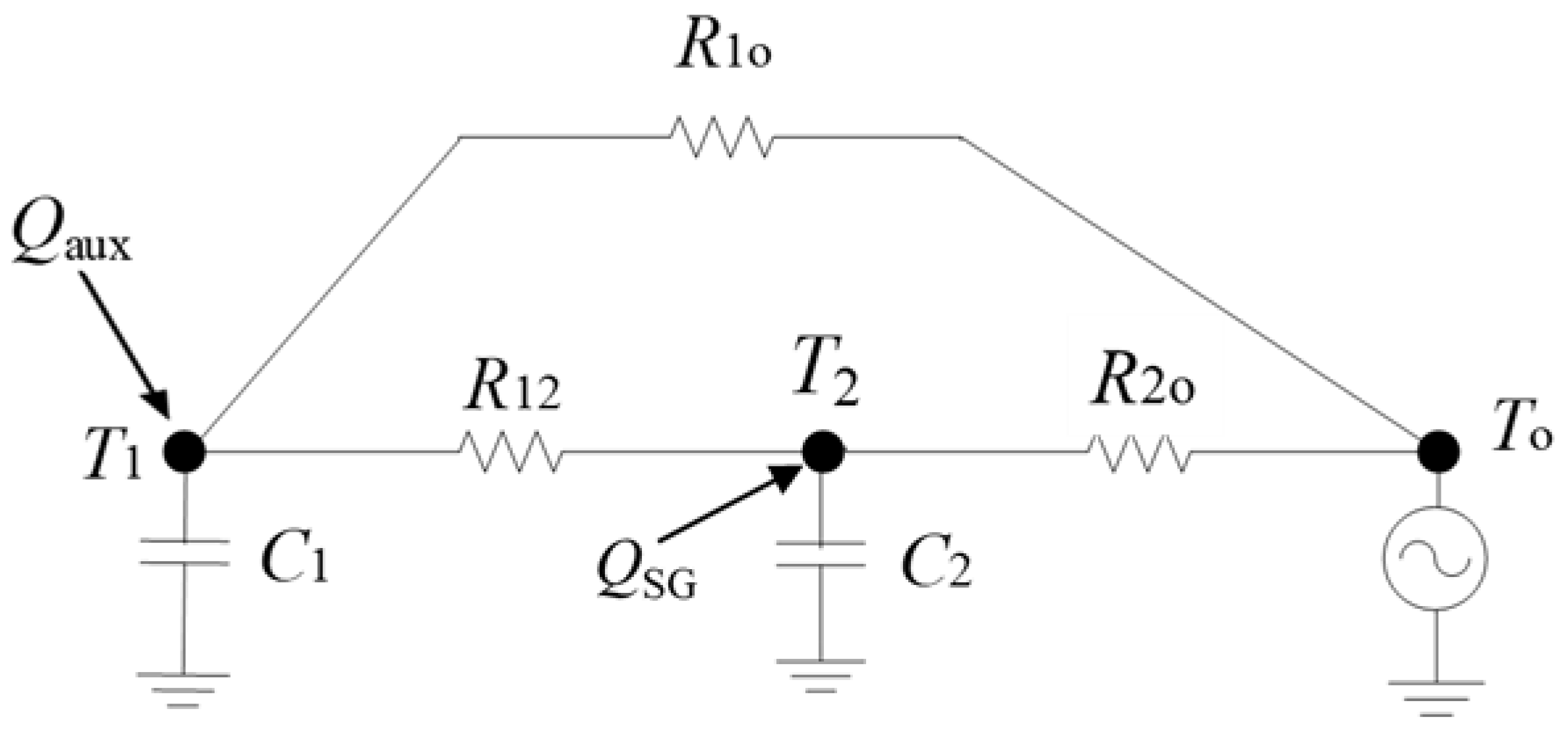
The model considered here is a second-order (2C) model in which one capacitance represents the thermal mass of the building envelope (C2), and the other capacitance represents the interior thermal mass of the building (C1), including indoor air (T1). The R2o represents the thermal resistance of the building envelope and the exterior film coefficient. The R1o represents infiltration, and R12 represents indoor heat transfer. Figure 2 shows the RC thermal network of the model.
Several experiments were performed in the case study building to collect data for model calibration and validation. The data collected over a 15 min time interval include the temperatures in the office area of the building, the chillers’ flow rates, and the supply/return temperatures. Using the measured data, the grey-box model parameters were calibrated. An optimization formulation was considered to minimize the error between the measured and RC models’ indoor air temperature by finding and assigning the effective values of the capacitances and resistances of the low-order RC model. If Ti represents the measured indoor air temperature and T i ^ represents simulation result, then the objective function J based on the second norm difference can be defined as follows:
J = T i T i ^ = i ( T i T i ^ ) 2
The MATLAB R2024a Optimization ToolboxTM was used here to solve the optimization problem. The model should satisfy the fitting criteria of the coefficient of variance of the root mean square error (CV–RMSE). As suggested by ASHRAE guideline 14, a model should not exceed a CV–RMSE of 30% relative to hourly measured data [38]. The CV–RMSE is calculated as follows:
C V R M S E ( % ) = 100 × [ i = 1 n ( T i T i ^ ) 2 / n ] T ¯
where n is the total number of observations, and T ¯ is the average of all measurements.
The resulting CV–RMSE was 3%, which is <30%. The simulation result from the calibrated model versus the measurement data is shown in Figure 3. This calibrated model was then used to study the selected control strategies and energy flexibility KPIs, as described in the following sections.

2.3. Flexibility Activation Strategies

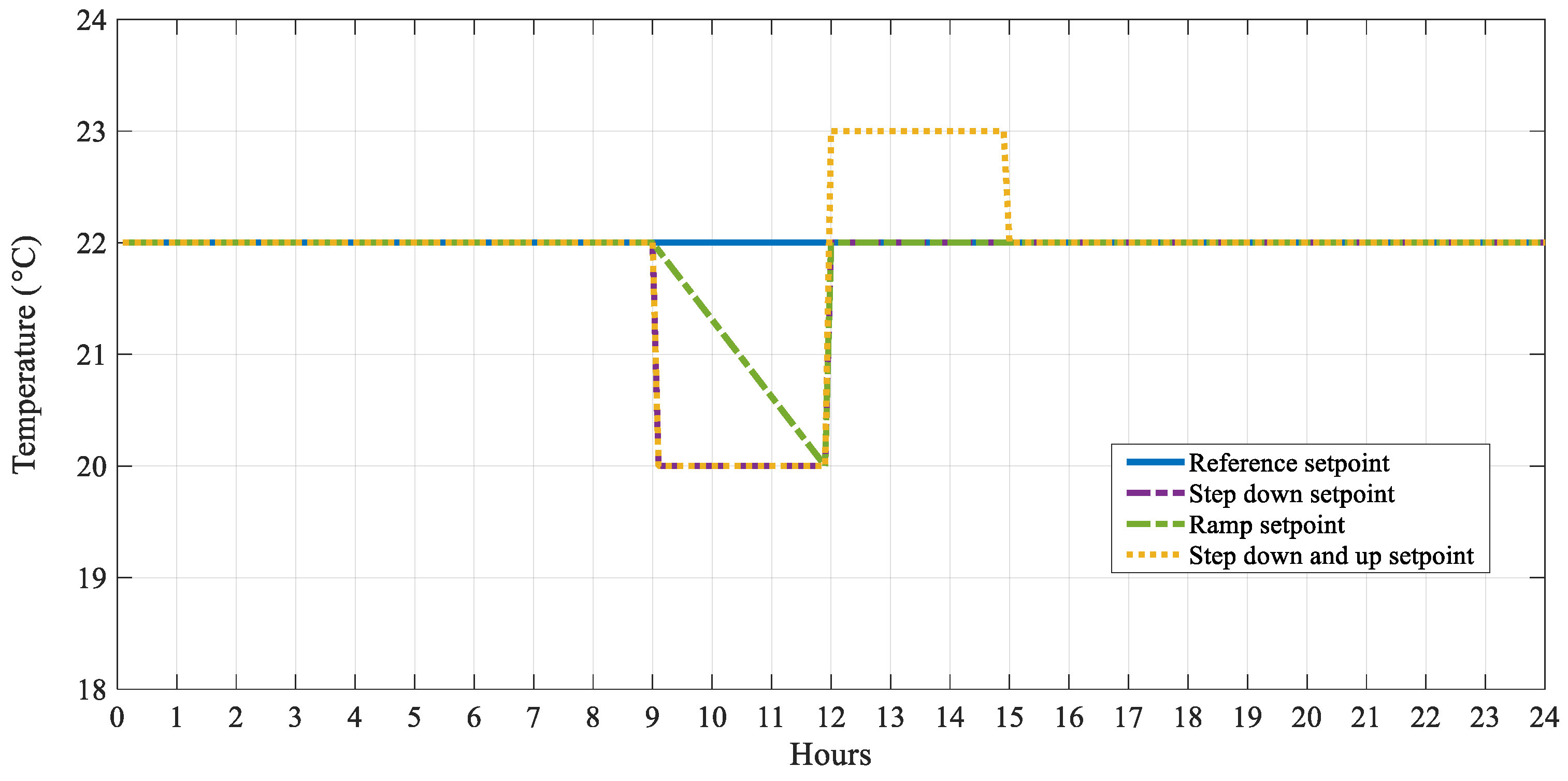
The flexibility strategies utilized in this study are based on the modulation of the indoor air temperature setpoint and its deviation from the standard operating conditions of the building during specific periods of the day. The normal operating condition involves maintaining a constant indoor setpoint temperature of 22 °C for the whole day. In the case of Dubai during August, the daily peak demand period was determined to be between noon and 15:00. The flexibility strategies are based on precooling the building before the peak demand period to shift the high consumption outside the peak period. The three strategies used to activate the flexibility are based on three different setpoint profiles, which are defined as follows:
(1)
Step setpoint reduction daily from 9:00 to 12:00:
{ f o r   9 h r s t 12 h r s ,   T s p = 20   ° C o t h e r w i s e , T s p = 22   ° C
(2)
Ramp setpoint reduction (from 22 °C to 20 °C) daily from hour 9 to 12:
{ for   9 h r s t 12 h r s ,   ramp   transition   T sp = m x + 22   ° C otherwise ,   T sp = 22   ° C  
(3)
Step down (setpoint reduction from hour 9 to 12) and up (setpoint increase from hour 12 to 15):
{ for   9 h r s t 12 h r s ,   T sp = 20   ° C for   12 h r s <   t 15 h r s ,   T sp = 23   ° C otherwise ,   T sp = 22   ° C  
Figure 4 shows all the different setpoint profiles considered. The blue line shows the reference baseline setpoint of 22 °C, which is constant and does not change during the day. The other lines show the three strategies mentioned above based on the deviation from the reference setpoint. The main difference between the strategies is the transition path from 9:00 to 12:00, and the third strategy includes an increase of 1 °C during the peak period from 12:00 to 15:00.

2.4. Flexibility KPIs

2.4.1. Available Structural Storage Capacity (CADR)

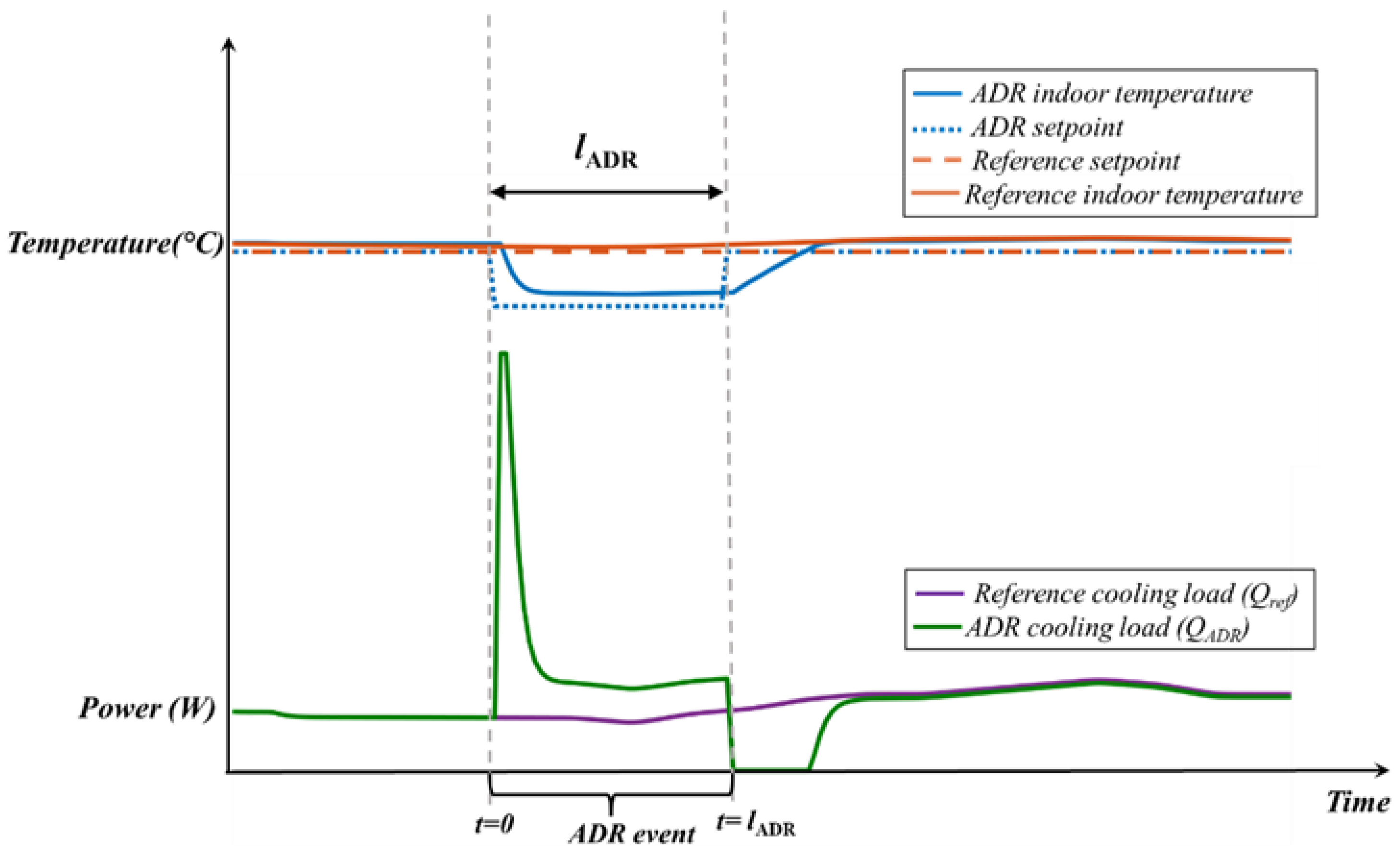
The available structural storage capacity (CADR) is defined as the amount of cooling (or heating) that can be added to the structural mass of a building during the active demand response (ADR) period without jeopardizing indoor thermal comfort. The CADR is calculated as the integral of the difference between the reference and flexible load profiles as [39]:
C A D R = 0 l A D R ( Q A D R Q R e f ) d t
where QADR is the flexible cooling load (W) and QRef is the reference cooling load (W). The lADR is the length/duration of the flexibility event. The concept is shown in Figure 5.

2.4.2. Peak-Period Energy Reduction (CRP)

From the stored energy during the ADR event, there will be a reduction in the load afterward during the demand period, which, compared with the reference case, can be calculated as follows:
C R P = Peak , t 0 Peak , t e n d ( Q R e f Q A D R ) d t

2.4.3. Load Factor (LF)

The load factor is the ratio of the average daily demand over the peak daily demand [40]. It indicates how well the generation assets in the system are utilized. The load factor approaching unity indicates a nearly constant use of the assets.
L F = Q ¯ Q max

2.4.4. System Ramping (SR)

System ramping measures the total absolute daily change in portfolio electricity demand from one interval to another [41]. The metric indicates how much demand changes in total over the course of a day. It is calculated from the sum of the absolute values of the shift from one time-step period to another over the course of each day. It is calculated for both the reference and flexible operation cases. The equation is as follows:
S R = i | Q i + 1 Q i |   ;   i ( 1 , n )

2.4.5. Cost Saving (CS)

This indicator calculates the cost saving achieved from implementing each strategy compared with the reference baseline scenario operation of the building. It is defined as follows:
C S = [ Q r e f ( t ) × Cos t ( t ) ] [ Q f l e x ( t ) × Cos t ( t ) ]
where Cost(t) is the marginal cost of electricity, and Qref and Qflex are the reference and flexible loads, respectively.

3. Results

This section presents the results of implementing the introduced flexibility strategies and the analysis of different indicators for each strategy. Then, it includes a comparison of the strategies.

3.1. Reference Baseline Load Profile

Figure 6a shows the baseline load profile of the building’s HVAC system for maintaining the reference constant indoor temperature setpoint of 22 °C for the whole month of August. On the other hand, Figure 6b presents the calculated daily load factors for each day of the month, considering the reference setpoint profile of 22 °C. In this case, the load factor fluctuates between 0.58 and 0.85.
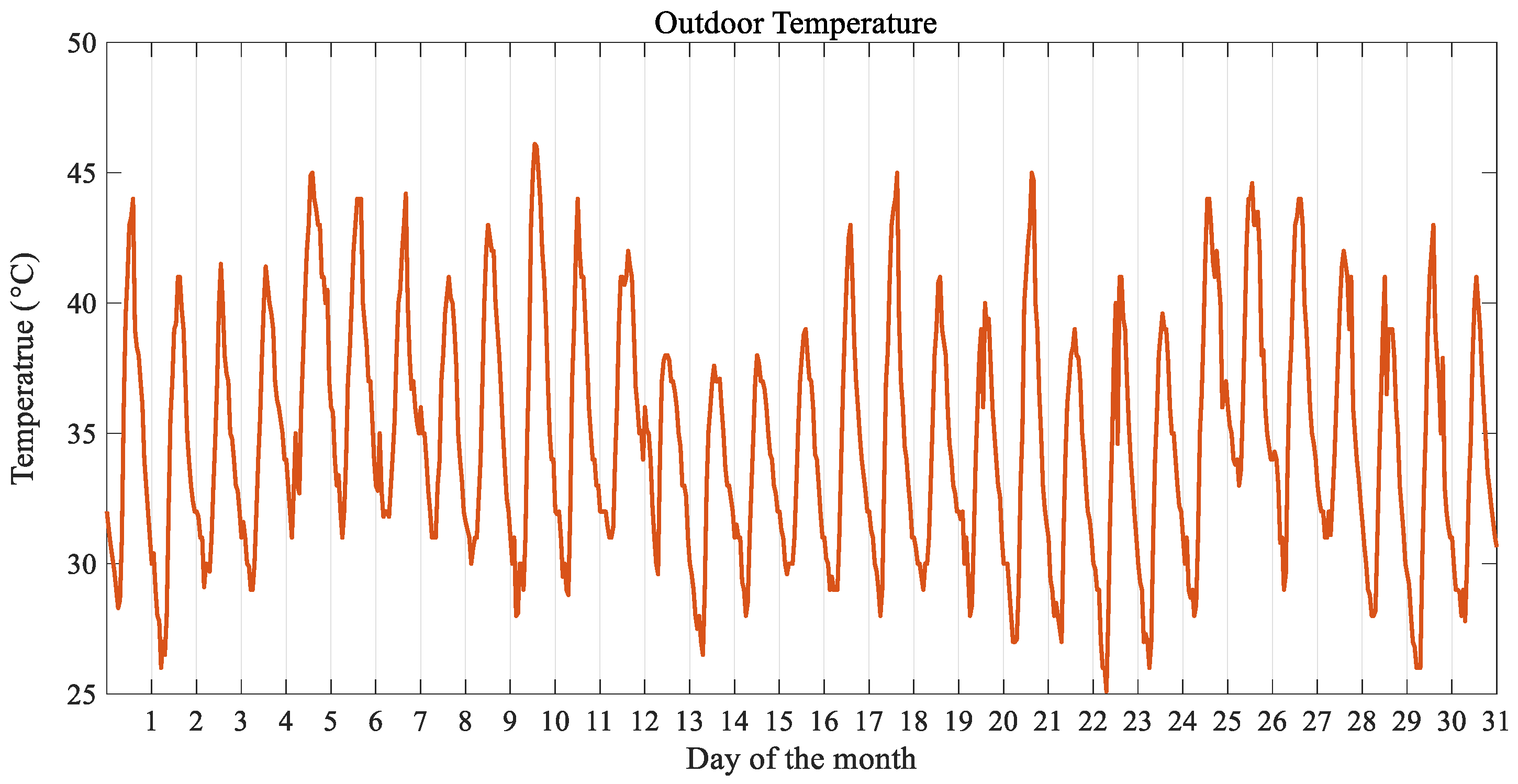
While evaluating load factors and the daily outdoor temperature profile Figure 7, it was observed that the increased daily swing in outdoor temperature generally results in a lower load factor. This observation is interesting because, on days with a large swing in outdoor temperatures, the peak load is substantially higher than the average load for that day, leading to a low calculated load factor. On the days with a smaller swing, the peak load is closer to the average load; thus, higher load factors are calculated. For example, on day 10, in which a relatively low load factor of 0.58 is calculated, a large swing in the outdoor temperature is observed with the temperature reaching beyond 46 degrees from the low of 28 degrees at night (18 degree swing). On day 13, when there was a much smaller swing of 8 degrees in the outdoor temperature, a load factor of 0.86 was calculated. A lower load factor means that the cooling system needs to work harder to handle the significant amplitude fluctuations. This scenario also means that the system needs to do more ramping up and down, which results in increased overall system ramping, as shown in Figure 8. The inverse relationship between the load factor and system ramping is presented in Figure 9.

Marginal Costs of Electricity

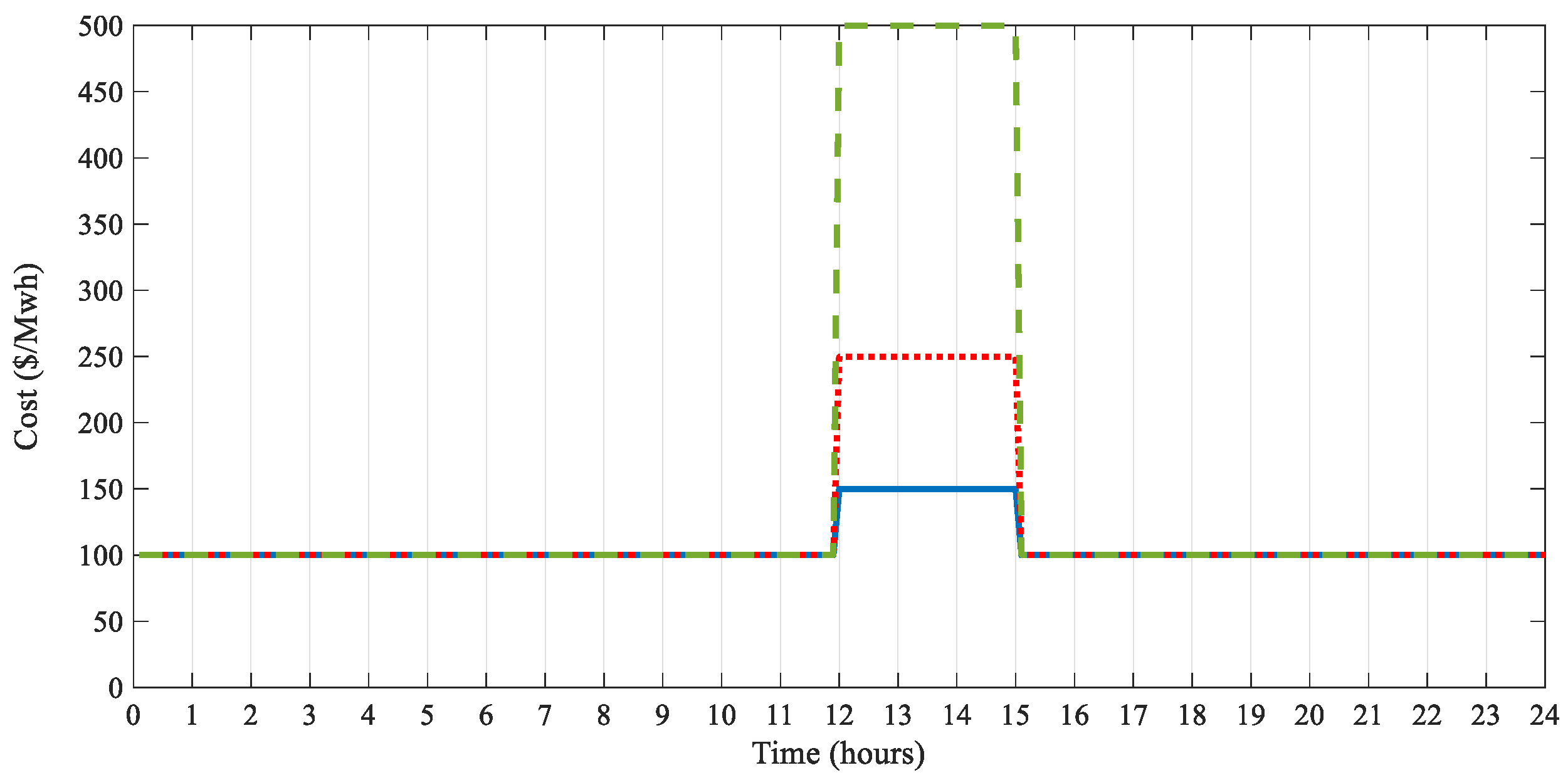
In this study, the period between hours 12 and 15 was considered the peak demand period, which is typical in Dubai. Figure 10 shows this study’s hypothetical marginal costs of electricity. The hypothetical reference cost of electricity is considered to be $100/MWh. The cost profiles are considered such that the cost is increased during the peak period from the reference price of $100/MWh to $150, $250, and $500/MWh, respectively. This part of the study aims to observe and compare the changes in flexibility indicators (KPIs), considering these three cost profiles on the applied flexibility strategies. This study was performed for the month of August, the hottest month in Dubai.

3.2. Energy Flexibility Strategies

Precooling the building three hours before the peak demand period, hours 9–12, was considered. This period is called the active/automated demand response (ADR) period [42]. The following subsections explain the results of the three setpoint strategies considered in this study.

3.2.1. Strategy #1: Step Profile

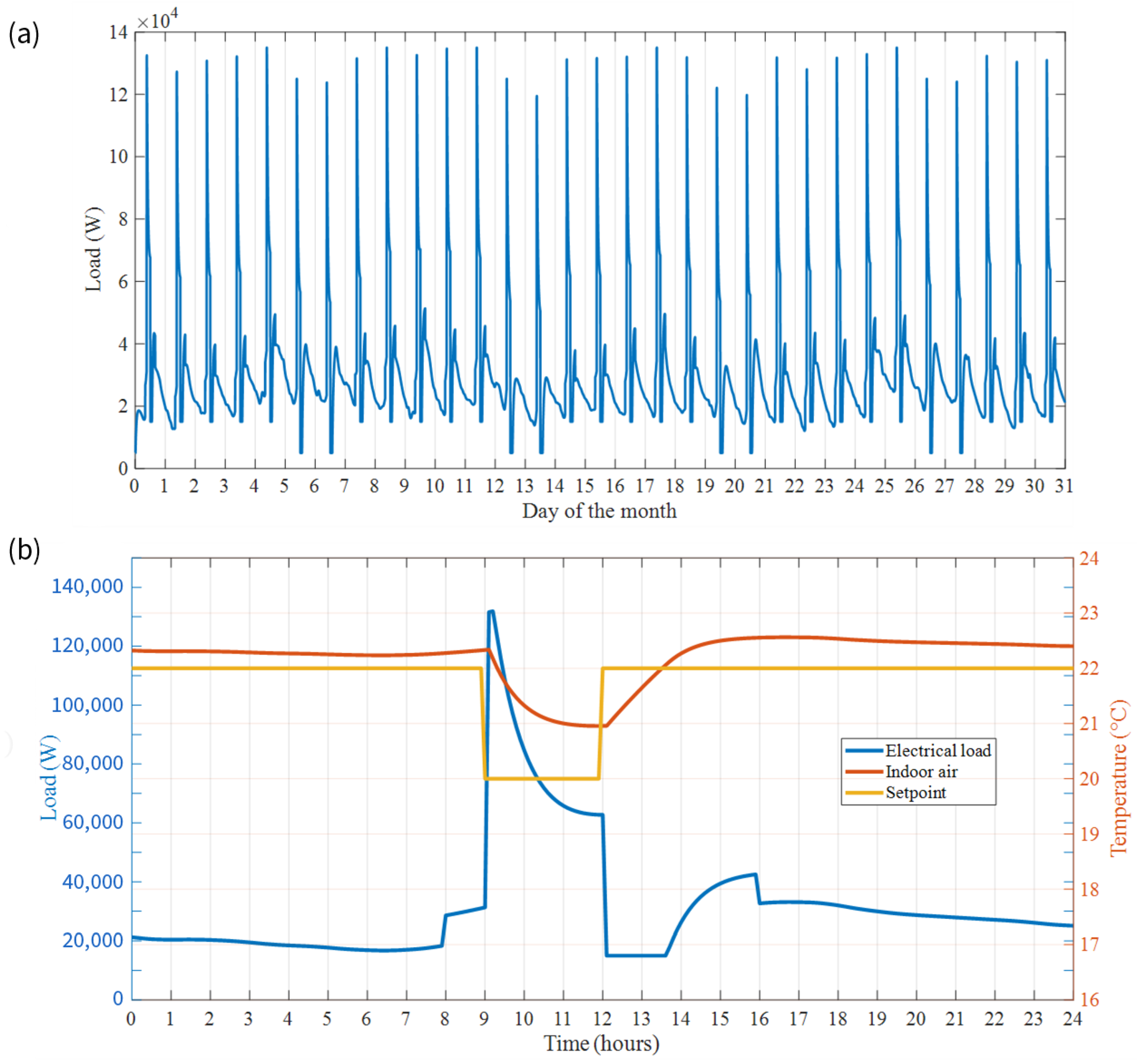
The baseline indoor air temperature setpoint is assumed to be 22 °C. The first strategy involves lowering the setpoint from 22 °C to 20 °C as a step change at 9 and then returning to 22 °C at 12 just before the peak demand period. Figure 11a shows the load profile for the entire month when strategy #1 was implemented. Figure 11b provides a closer look at how this strategy affects electrical load changes during a day in August compared with the reference load profile.
The load changes suddenly and increases to the maximum capacity when the setpoint is decreased from 22 °C to 20 °C. This precooling makes the load significantly lower during the peak period. For approximately 1.8 h (from 12–13.8), the electrical cooling load was zero, with the only load being the base building load (lighting, plug-in, and miscellaneous loads).
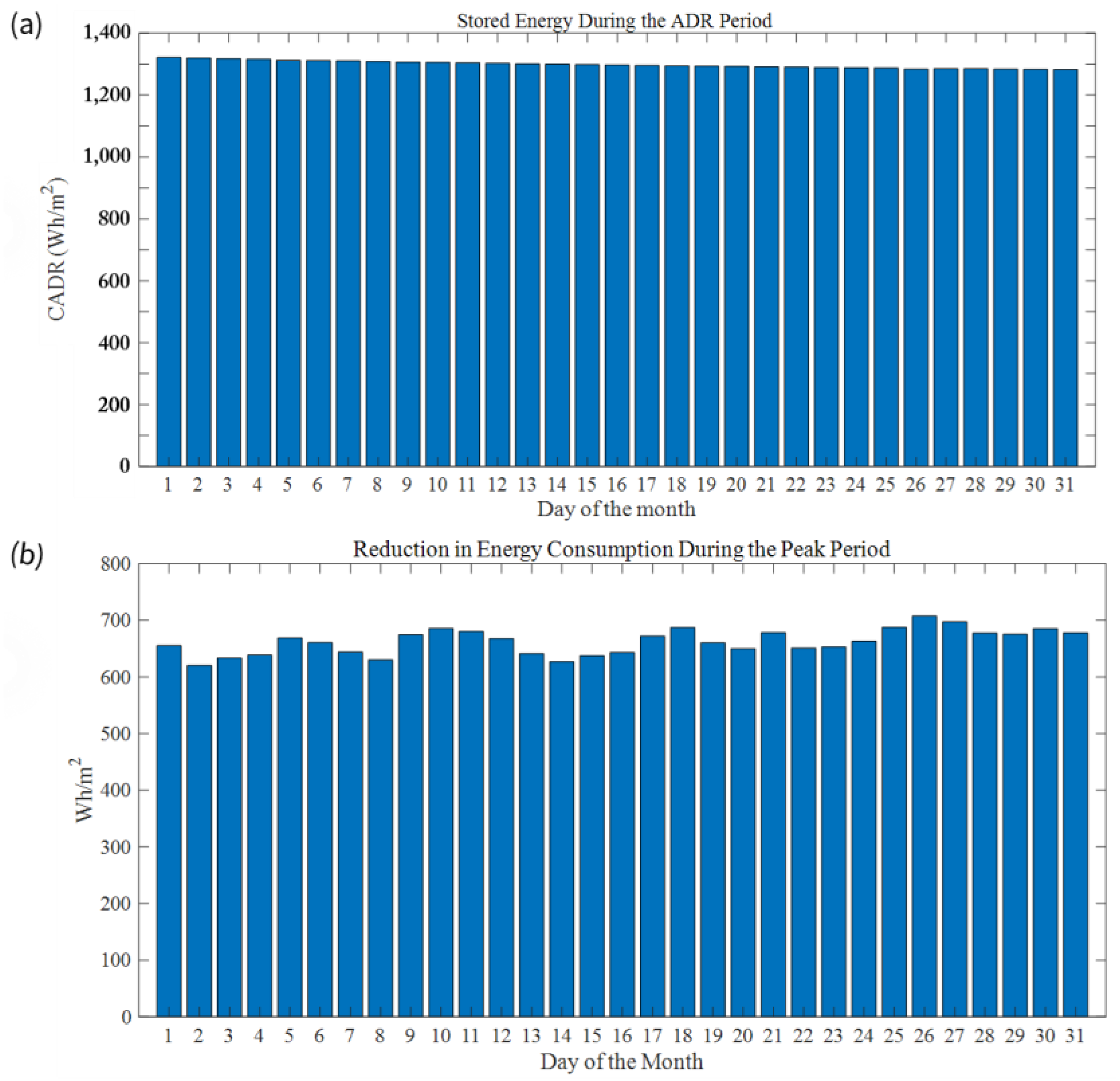
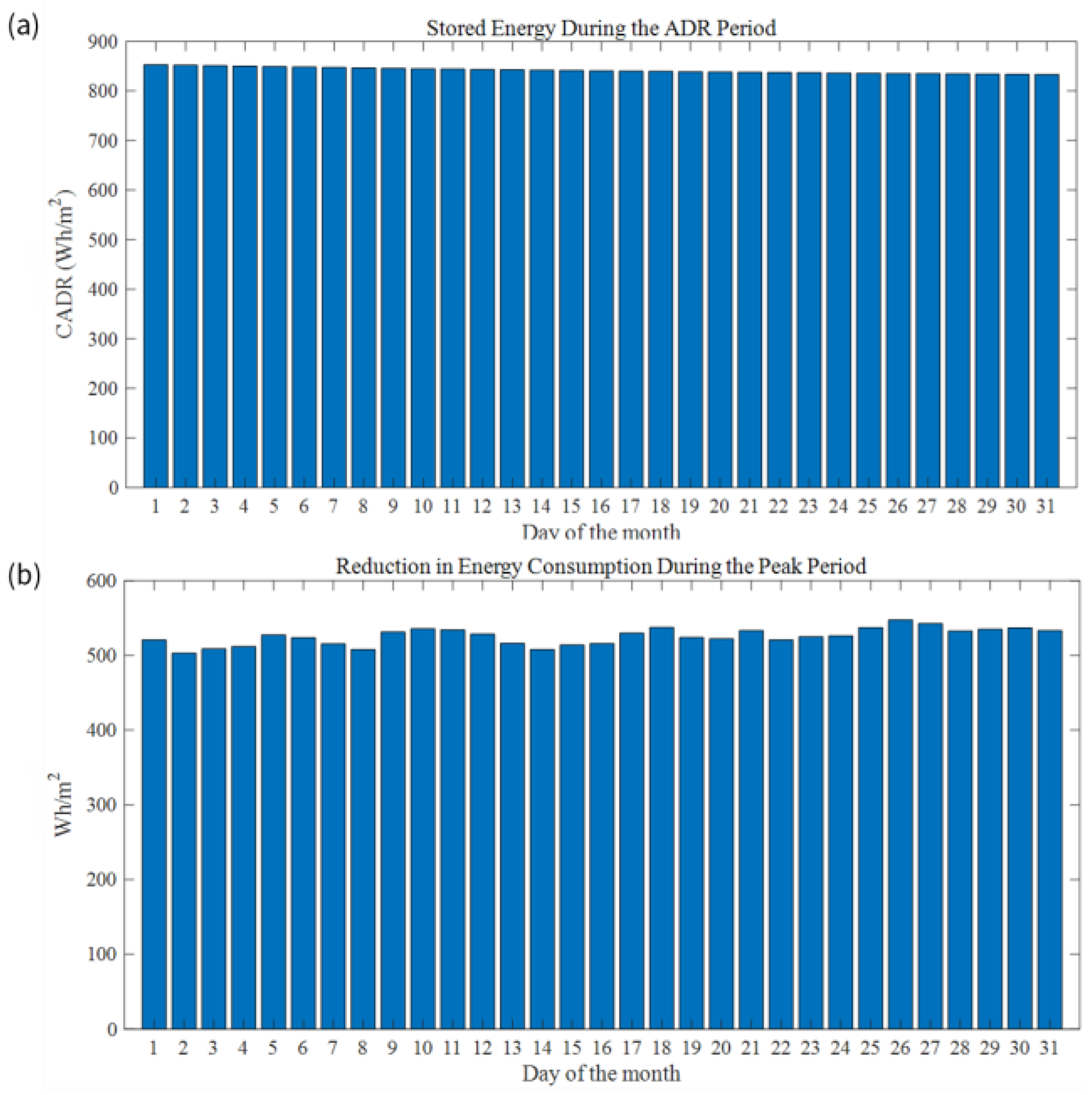
Figure 12a shows the available storage capacity (CADR) during the ADR period for each day of the month. The CADR is almost the same value for all days since this indicator is the difference between the reference and flexible load profiles. The slight downward trend is due to the slightly accumulated storage from the previous day. The change in CADR from one day to the next is very small and less than 0.15%. However, the total difference between the first and last days of the month is 3%. The average CADR was calculated as 1.3 kWh/m2. The above storage during the ADR period results in decreased energy consumption during the peak period, which is shown in Figure 12b. For each day in August, energy consumption during the peak period is reduced by 0.65 to 0.7 kWh/m2.
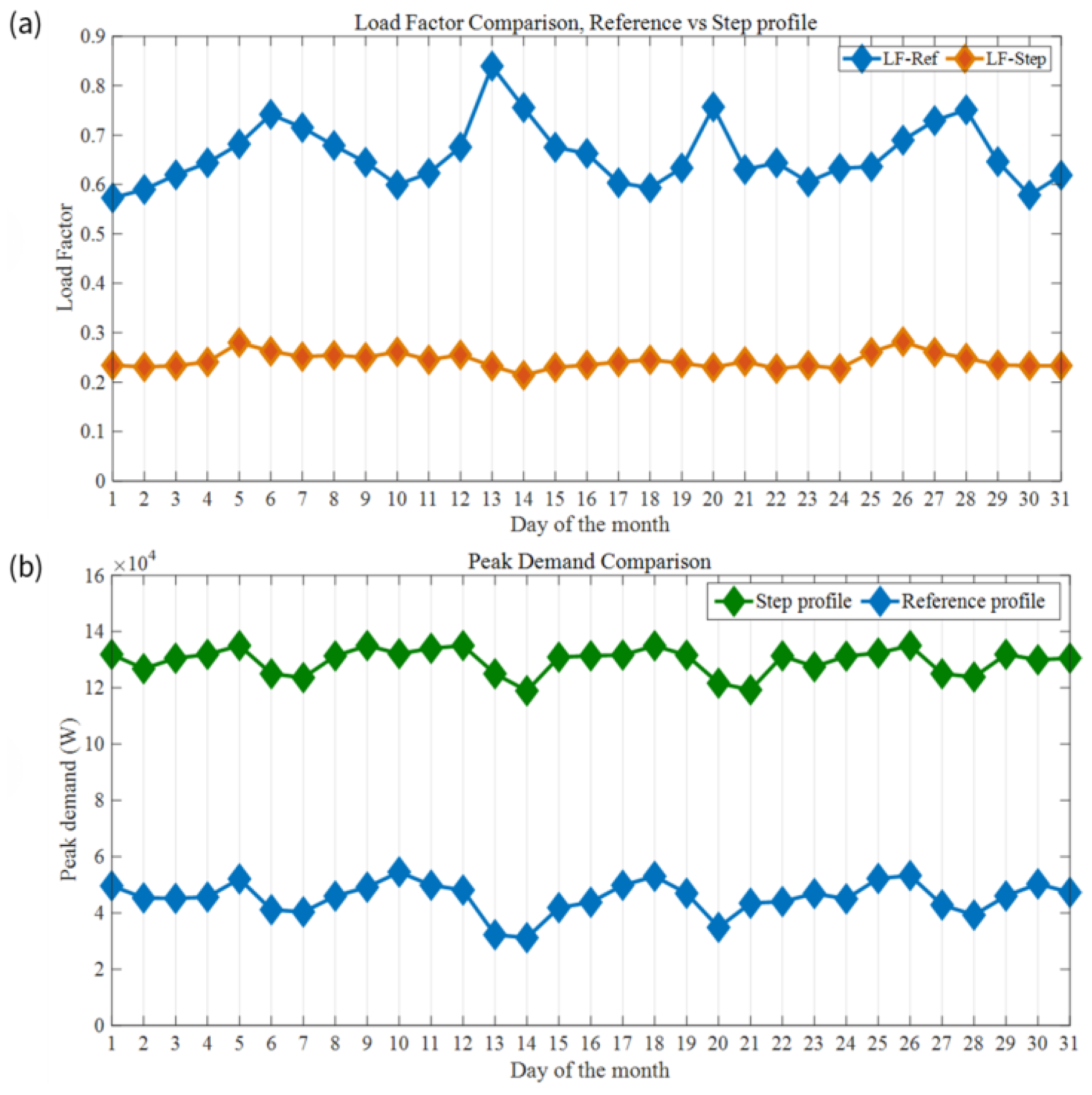
A comparison between the values of the new daily load factor and the reference profile is shown in Figure 13a. In general, the load factor values are significantly lower than those for the reference case, with an average of 0.66 for the reference case and 0.244 for the step profile. The reason is the significant increase in the daily peak demand with a sudden decrease in the setpoint during the ADR period, as shown in Figure 13b.
In terms of the total cost comparison for three different cost signals (shown in Figure 10), Table 1 shows the difference in cost between the flexible setpoint strategy and the reference case and the cost increase/decrease. As observed from Table 1, the economic justification for implementing the flexibility strategy depends on how much the cost is increased compared with the baseline. For the first cost signal, the cost signal increased by only 50% from $100/MWh to $150/MWh during the peak period.
Compared with normal operating conditions, the total cost slightly increases. Therefore, this flexibility strategy is not economically justifiable for this cost curve. However, as the cost is increased by 150% and 400% to $250/MWh and $500/MWh, the total monthly cost is reduced by 5.9% and 17.3%, respectively. Therefore, this total cost reduction/increase is an important point to consider for the economic justifiability of a flexibility strategy.
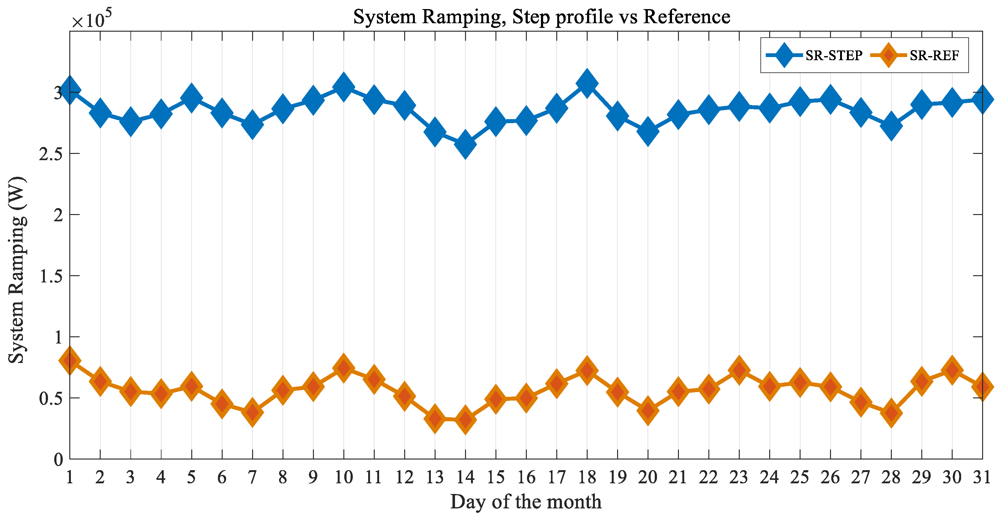
With respect to system ramping, a significant increase in total daily ramping is observed compared with the reference case, as shown in Figure 14.

3.2.2. Strategy #2: Ramp Profile

For the second strategy, the setpoint profile was adjusted to implement a linear ramp for the temperature reduction transition from 22 °C to 20 °C during the active demand response (ADR) period. Figure 15a shows the load profile for the whole month, and Figure 15b presents the hourly load profile of a representative day in August. As shown in these figures, this strategy produces a smoother load profile than the step profile.
As observed, the change in the load is much smoother than that of the previous strategy because of the ramp transition trajectory for the setpoint. Hence, the peak power (≈98 kW) is significantly lower than that of the previous strategy (≈130 kW), which can be a significant consideration when designing strategies.
The daily storage during the ADR event (CADR) is shown in Figure 16a. Less energy (0.84 kWh/m2) was stored with the ramp strategy because of a smoother change in the load profile than in the step profile (1.3 kWh/m2). The reduction in energy consumption during the peak period is shown in Figure 16b. The load factor for this strategy is also lower than that of the reference profile but higher than that of the step change setpoint, as shown in Figure 17.
Based on the comparison of load factors between the two strategies shown in Figure 17, there is a trade-off between higher storage, smoother load profile change and the load factor. Since the load factor indicates how well the generation assets are utilized in the system, it is generally desirable to have the load factor as close to one as possible. Therefore, this is an important parameter that should be reported to the DSO along with the available storage capacity during the ADR period and the energy consumption reduction during the peak demand period.
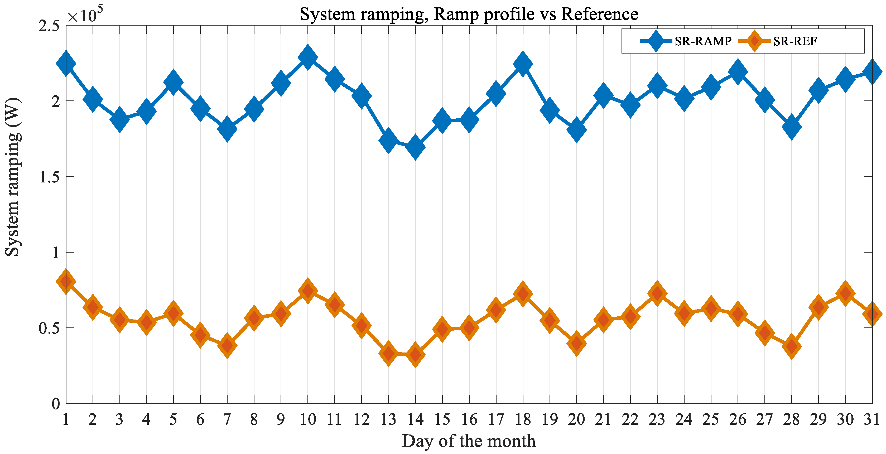
In terms of cost change, Table 2 shows the comparison between the reference case and strategy #2. This strategy’s cost reduction is less than that of the previous step profile because of the smoother transition and load profile. Additionally, in terms of system ramping, a lower daily ramping than that of strategy #1 (step profile) was observed, as shown in Figure 18.

3.2.3. Strategy #3: Step down and up Profile

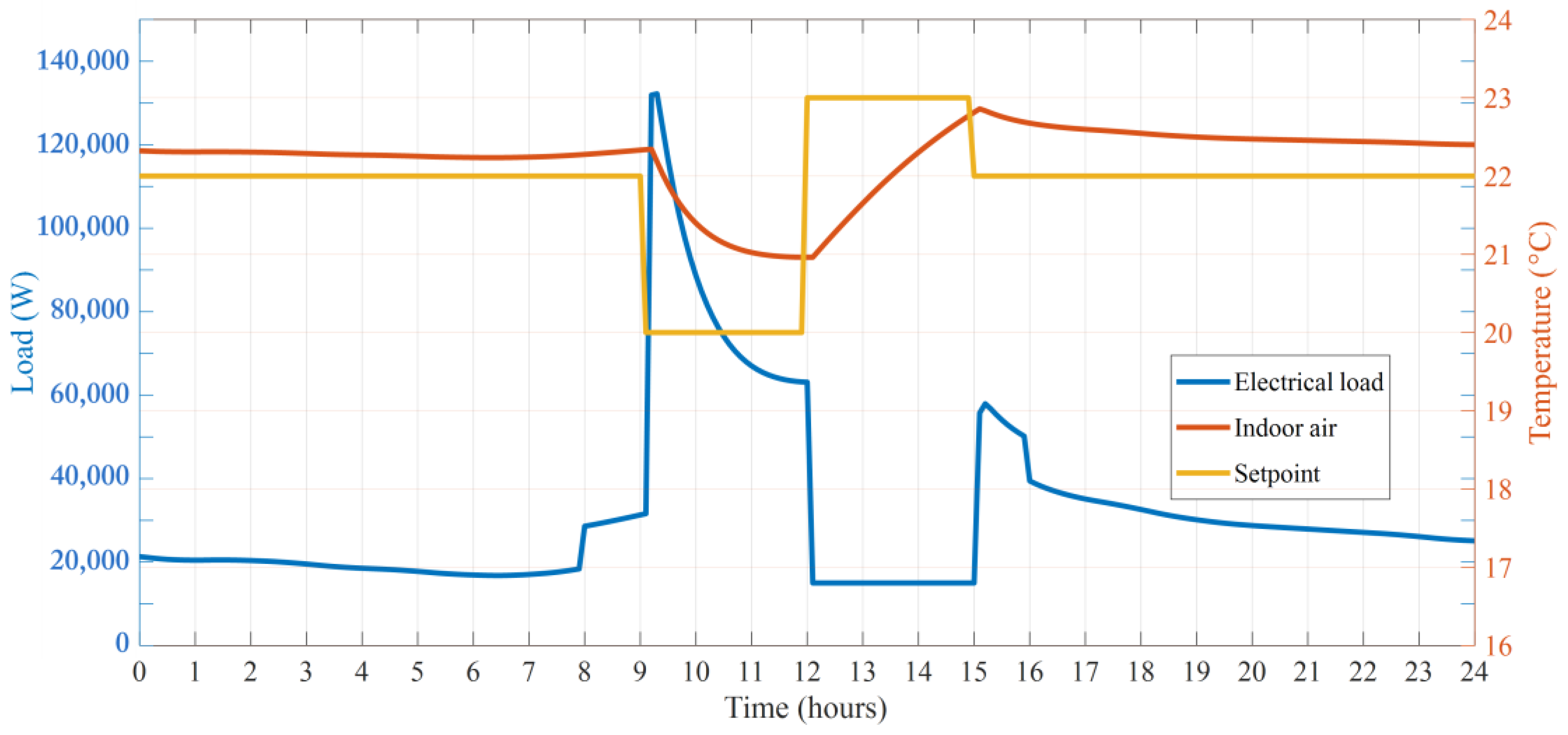
This strategy is similar to the first step strategy, the only difference is that in addition to lowering the setpoint temperature from 22 °C to 20 °C during the active demand response (ADR) period, the setpoint temperature is increased to 23 °C during the peak period (instead of the reference 22 °C). This helps to keep the load lower during the peak demand period while the indoor air is still within the comfort range, as shown in Figure 19.
Since the ADR period strategy is the same as the first one, the CADR is also the same (1.3 kWh/m2). However, due to the setpoint increase of 1 °C during the peak period, there is a higher reduction in the load. Figure 20 shows that when strategy #3 is implemented, there is a 0.75–1.05 kWh/m2 reduction in the peak period energy consumption (CRP).
The major noticeable difference here is the increased system ramping compared to the first step profile due to the additional change in the setpoint during the peak period. Figure 21 shows the comparison of system ramping between strategy #3 and the baseline scenario. In terms of cost, the most significant reduction is gained with this strategy, as shown in Table 3.

4. Discussion

This section discusses the findings from the implementation of the three studied activation strategies organized by the five flexibility indicators.

4.1. Available Structural Storage Capacity (CADR) and Peak-Period Energy Reduction (CRP)

Since the precooling of strategy #1 (step profile) and strategy #3 (step down and up profile) is equal, these strategies have the same CADR of 1.3 kWh/m2. However, when strategy #3 is implemented, raising the set temperature by one degree results in a more substantial reduction in peak-period energy consumption (CRP = 0.75–1.05 kWh/m²) compared to the reduction achieved with strategy #1 (CRP = 0.65–0.70 kWh/m²).
On the other hand, strategy #2 (ramp profile) leads to 34% lower CADR (0.84 kWh/m2) than strategy #1. However, this strategy results in the smoothest change in the load and more than 30% reduction in the peak-period energy reduction compared with strategy #1.

4.2. Load Factor (LF) and System Ramping (SR)

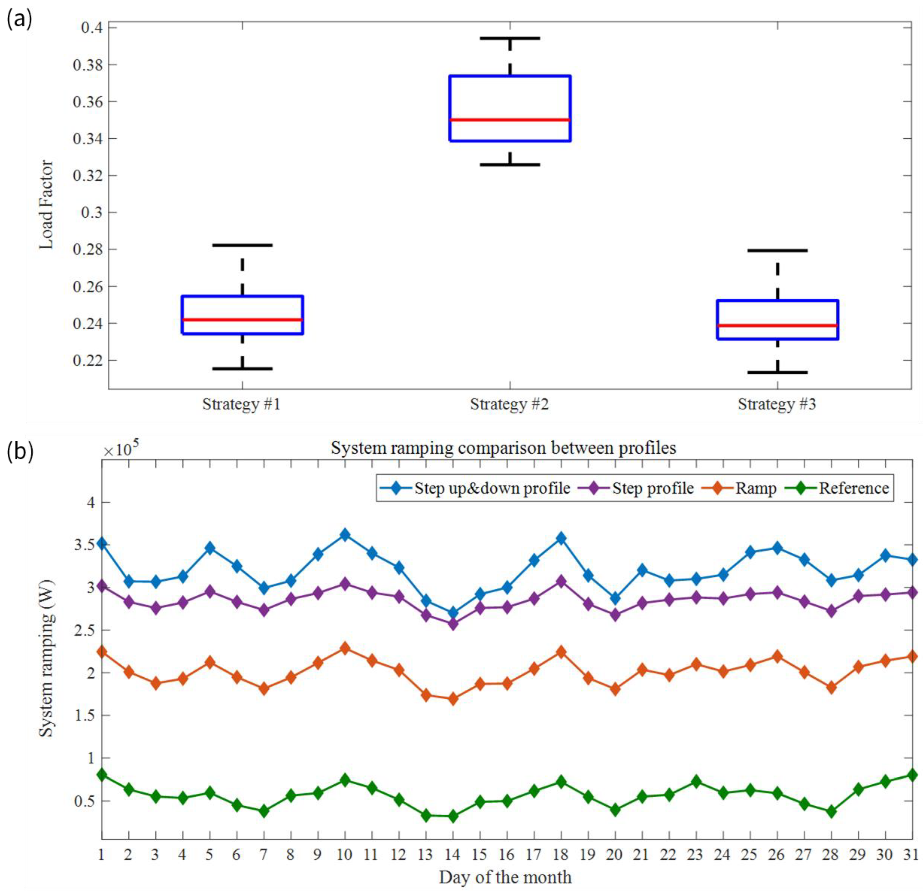
For the reference load profile, it was observed that the magnitude of outdoor temperature fluctuations has a noticeable effect on the load factor, where generally, large swings in the outdoor temperature decrease the load factor. Figure 22a shows box-and-whisker plots for comparing the load factors of different strategies. Figure 22b shows the system ramping comparison for all the strategies. Compared with those of the other two strategies, the load factor is greater for the ramp profile strategy; hence, the system ramping is lower.

4.3. Summary of the Four Flexibility Indicators and Cost Saving (CS)

Table 4 summarizes the previous discussion, showing each strategy’s average results, including average available structural storage capacity (CADR), average peak-period energy reduction (CRP), average load factor (LF), and average system ramping (SR).
Figure 23 demonstrates how the magnitude of the increase in the marginal cost during the peak period justifies the economic aspect of each strategy on each of the three marginal cost signals studied. All analyzed strategies lead to cost savings that are independent of the cost signal, except for strategy #1 with cost signal 1. With this cost signal, even for strategies #2 and #3, the cost decrease barely justifies the effort of implementing flexibility strategies. However, for cost signals 2 and 3, the cost savings from implementing flexibility strategies are significant. Additionally, strategy 3 (step down and up) yields the highest cost savings among all three strategies.

5. Conclusions

This study presented and evaluated three energy-flexibility strategies to enhance the operation of a building’s air conditioning system in Dubai’s hot climate. The following studied strategies are based on the use of the building thermal mass and the modulation of the indoor air temperature setpoint profile: strategy #1 (step profile), strategy #2 (ramp profile), and strategy #3 (step down and up profile). The strategies’ assessment was performed considering three electricity cost signals with different amplitude increases during the peak demand period, which were based on the following five key performance indicators: available structural storage capacity (CADR), peak-period energy reduction (CRP), load factor (LF), system ramping (SR), and cost saving (CS). The study demonstrates the value and insights gained from combining different indicators in analyzing flexibility strategies. The insights not only include the storage and energy reduction capacity but also the stability of the system and the way a flexibility strategy affects the load factor. This combination of indicators helps the users weigh whether implementing a specific flexibility strategy is a good idea or not. A strategy can significantly reduce the peak-period energy consumption but can also increase the system ramping too much and outside the desirable range which is not good for the system.
Additionally, the results emphasize the importance of selecting appropriate flexibility strategies based on specific objectives and economic goals. For scenarios where cost saving is the main objective, particularly under high peak-period electricity prices, strategy #3 proves most beneficial. Conversely, if the goal is to enhance system stability and reduce operational stress, strategy #2 is preferable because of its smoother load transitions and lower ramping requirements.
The economic viability of each strategy was highly dependent on the difference between the normal and peak-period electricity costs. Strategies yielded minimal economic benefits under a modest cost increase at the peak periods (cost signal 1) but became increasingly advantageous as the peak-period cost increased. With cost signals 2 and 3, the cost reduction was greater than 5.6% in all cases, reaching 26% in the best case.
The effective implementation of energy flexibility strategies offers a practical solution for addressing peak demand period challenges while lowering operational costs, thereby supporting sustainable energy management. It is also important to acknowledge the limitation of this study, as it relies on five specific indicators that are tailored to the characteristics of the location. For other cases where other aspects of system performance are important or buildings are in different locations, additional relevant indicators should be considered. For example, an indicator which specifically evaluates the change in the peak power demand for the locations where the peak power consumption is part of the cost and tariff structure should be considered.
Future work will focus on expanding this study to building clusters and communities and developing strategies at the community level to combine the flexibility of multiple buildings.

Author Contributions

Conceptualization, A.S.-D.; methodology, A.S.-D.; software, A.S.-D.; validation, A.S.-D., J.D.B. and E.R.-U.; formal analysis, A.S.-D.; investigation, A.S.-D., J.D.B. and E.R.-U.; resources, A.S.-D., J.D.B. and E.R.-U.; data curation, J.D.B. and A.S.-D.; writing—original draft preparation, A.S.-D., J.D.B. and E.R.-U.; writing—review and editing, A.S.-D., J.D.B. and E.R.-U.; visualization, A.S.-D., J.D.B. and E.R.-U.; supervision, E.R.-U.; project administration, E.R.-U.; funding acquisition, E.R.-U. All authors have read and agreed to the published version of the manuscript.

Funding

This research received no external funding.

Data Availability Statement

The data that support this article’s findings are not openly readily available. Requests to access the datasets should be directed to the Dubai Electricity and Water Authority (VP.R&[email protected]).

Acknowledgments

The authors would like to acknowledge Dubai Electricity and Water Authority (DEWA) for funding this research and Sgouris Sgouridis, director of the DEWA R&D Centre, for his valuable comments.

Conflicts of Interest

The authors declare no conflicts of interest.

Nomenclature

ADRActive Demand ResponseQrefReference cooling power profile
BMSBuilding management systemQADR/flexFlexible cooling power profile
CiThermal capacitance of node iRi,jThermal resistance between nodes i and j
CADRAvailable structural storage capacityRCResistance capacitance
CRPPeak-period energy reduction R12Internal heat transfer
CSCost SavingR1oinfiltration
kThermal conductivity of materials R2oThermal resistance of building envelope
KPIKey performance indicatorSRSystem ramping
LADRLength of the ADR eventTiTemperature of node i
LFLoad factorTspAir setpoint temperature
QmaxMaximum cooling capacityToOutdoor temperature
QauxCooling/heating ΔtTime step
QsgSolar gain

References

  1. Cao, X.; Dai, X.; Liu, J. Building energy-consumption status worldwide and the state-of-the-art technologies for zero-energy buildings during the past decade. Energy Build. 2016, 128, 198–213. [Google Scholar] [CrossRef]
  2. IEA EBC. Annex 67—Energy Flexible Buildings. Available online: https://www.annex67.org/ (accessed on 1 August 2024).
  3. IEA EBC. Annex 82—Energy Flexible Buildings Towards Resilient Low Carbon Energy Systems. Available online: https://annex82.iea-ebc.org/ (accessed on 7 August 2024).
  4. IEA EBC. Annex 81—Data-Driven Smart Buildings. Available online: https://annex81.iea-ebc.org/ (accessed on 31 July 2024).
  5. Satchwell, A.; Piette, M.A.; Khandekar, A.; Granderson, J.; Frick, N.M.; Hledik, R.; Faruqui, A.; Lam, L.; Ross, S.; Cohen, J.; et al. National Roadmap for Grid-Interactive Efficient Buildings; Lawrence Berkeley National Laboratory: Berkeley, CA, USA, 2021. [Google Scholar]
  6. Jensen, S.Ø.; Marszal-Pomianowska, A.; Lollini, R.; Pasut, W.; Knotzer, A.; Engelmann, P.; Stafford, A.; Reynders, G. IEA EBC Annex 67 Energy Flexible Buildings. Energy Build. 2017, 155, 25–34. [Google Scholar] [CrossRef]
  7. Li, R.; Satchwell, A.J.; Finn, D.; Christensen, T.H.; Kummert, M.; Le Dréau, J.; Lopes, R.A.; Madsen, H.; Salom, J.; Henze, G.; et al. Ten questions concerning energy flexibility in buildings. Build. Environ. 2022, 223, 109461. [Google Scholar] [CrossRef]
  8. Saberi-Derakhtenjani, A.; Athienitis, A.K.; Eicker, U.; Rodriguez-Ubinas, E. Energy Flexibility Comparison of Different Control Strategies for Zones with Radiant Floor Systems. Buildings 2022, 12, 837. [Google Scholar] [CrossRef]
  9. Zhan, S.; Dong, B.; Chong, A. Improving energy flexibility and PV self-consumption for a tropical net zero energy office building. Energy Build. 2023, 278, 112606. [Google Scholar] [CrossRef]
  10. Carlucci, F.; Negendahl, K.; Fiorito, F. Energy flexibility of building systems in future scenarios: Optimization of the control strategy of a dynamic shading system and definition of a new energy flexibility metric. Energy Build. 2023, 289, 113056. [Google Scholar] [CrossRef]
  11. Li, H.; Johra, H.; de Andrade Pereira, F.; Hong, T.; Le Dréau, J.; Maturo, A.; Wei, M.; Liu, Y.; Saberi-Derakhtenjani, A.; Nagy, Z.; et al. Data-driven key performance indicators and datasets for building energy flexibility: A review and perspectives. Appl. Energy 2023, 343, 121217. [Google Scholar] [CrossRef]
  12. Vašak, M.; Banjac, A.; Hure, N.; Novak, H.; Kovačević, M. Predictive control based assessment of building demand flexibility in fixed time windows. Appl. Energy 2023, 329, 120244. [Google Scholar] [CrossRef]
  13. Derakhtenjani, A.S.; Barbosa, J.D.; Rodriguez-Ubinas, E. Evaluation of Energy Flexibility Potential of a Typical Thermal Zone in Dubai. Int. J. Energy Prod. Manag. 2022, 7, 265–275. [Google Scholar] [CrossRef]
  14. Awan, M.B.; Sun, Y.; Lin, W.; Ma, Z. A framework to formulate and aggregate performance indicators to quantify building energy flexibility. Appl. Energy 2023, 349, 121590. [Google Scholar] [CrossRef]
  15. Morovat, N.; Athienitis, A.K.; Candanedo, J.A.; Delcroix, B. Model-Based Control Strategies to Enhance Energy Flexibility in Electrically Heated School Buildings. Buildings 2022, 12, 581. [Google Scholar] [CrossRef]
  16. Kheiri, S.Z.; Mirzaei, M.A.; Parvania, M. Integrating the Energy Flexibility of Cold Climate Air Source Heat Pump in Home Energy Management Systems. In Proceedings of the 2024 IEEE Power & Energy Society Innovative Smart Grid Technologies Conference (ISGT), IEEE, Washington, DC, USA, 19–22 February 2024; pp. 1–5. [Google Scholar] [CrossRef]
  17. Rehman, H.U.; Hasan, A. Energy Flexibility and towards Resilience in New and Old Residential Houses in Cold Climates: A Techno-Economic Analysis. Energies 2023, 16, 5506. [Google Scholar] [CrossRef]
  18. Rehman, H.U.; Hasan, A. Energy flexibility and resiliency analysis of old and new single family buildings in Nordic climate. In Proceedings of the Building Simulation Conference, International Building Performance Simulation Association, Shanghai, China, 4–6 September 2023; pp. 326–333. [Google Scholar] [CrossRef]
  19. Liu, J.; Yang, X.; Liu, Z.; Zou, J.; Wu, Y.; Zhang, L.; Zhang, Y.; Xiao, H. Investigation and evaluation of building energy flexibility with energy storage system in hot summer and cold winter zones. J. Energy Storage 2022, 46, 103877. [Google Scholar] [CrossRef]
  20. Yang, X.; Pan, L.; Guan, W.; Ma, H.; Zhang, C. Heat flexibility evaluation and multi-objective optimized control of a low-energy building with district heating. Energy Build. 2022, 277, 112523. [Google Scholar] [CrossRef]
  21. Wilczynski, E.J.; Chambers, J.; Patel, M.K.; Worrell, E.; Pezzutto, S. Assessment of the thermal energy flexibility of residential buildings with heat pumps under various electric tariff designs. Energy Build. 2023, 294, 113257. [Google Scholar] [CrossRef]
  22. Luc, K.M.; Li, R.; Xu, L.; Nielsen, T.R.; Hensen, J.L.M. Energy flexibility potential of a small district connected to a district heating system. Energy Build. 2020, 225, 110074. [Google Scholar] [CrossRef]
  23. Foteinaki, K.; Li, R.; Péan, T.; Rode, C.; Salom, J. Evaluation of energy flexibility of low-energy residential buildings connected to district heating. Energy Build. 2020, 213, 109804. [Google Scholar] [CrossRef]
  24. Saberi-Derakhtenjani, A.; Athienitis, A.K. A frequency domain transfer function methodology for thermal characterization and design for energy flexibility of zones with radiant systems. Renew. Energy 2021, 163, 1033–1045. [Google Scholar] [CrossRef]
  25. Lu, F.; Yu, Z.; Zou, Y.; Yang, X. Cooling system energy flexibility of a nearly zero-energy office building using building thermal mass: Potential evaluation and parametric analysis. Energy Build. 2021, 236, 110763. [Google Scholar] [CrossRef]
  26. Afroz, Z.; Wu, H.; Sethuvenkatraman, S.; Henze, G.; Junker, R.G.; Shepit, M. A study on price responsive energy flexibility of an office building under cooling dominated climatic conditions. Energy Build. 2024, 316, 114359. [Google Scholar] [CrossRef]
  27. Triolo, R.C.; Rajagopal, R.; Wolak, F.A.; de Chalendar, J.A. Estimating cooling demand flexibility in a district energy system using temperature set point changes from selected buildings. Appl. Energy 2023, 336, 120816. [Google Scholar] [CrossRef]
  28. Mugnini, A.; Polonara, F.; Arteconi, A. Energy flexibility curves to characterize the residential space cooling sector: The role of cooling technology and emission system. Energy Build. 2021, 253, 111335. [Google Scholar] [CrossRef]
  29. Airò Farulla, G.; Tumminia, G.; Sergi, F.; Aloisio, D.; Cellura, M.; Antonucci, V.; Ferraro, M. A Review of Key Performance Indicators for Building Flexibility Quantification to Support the Clean Energy Transition. Energies 2021, 14, 5676. [Google Scholar] [CrossRef]
  30. Ruan, Y.; Ma, J.; Meng, H.; Qian, F.; Xu, T.; Yao, J. Potential quantification and impact factors analysis of energy flexibility in residential buildings with preheating control strategies. J. Build. Eng. 2023, 78, 107657. [Google Scholar] [CrossRef]
  31. Dubai Electricity and Water Authority (DEWA). DEWA Supports the Realisation of Sustainability through a Roadmap Based on Promising Projects and Eco-Friendly Practices. Available online: https://www.dewa.gov.ae/en/about-us/media-publications/latest-news/2024/02/dewa-supports-the-realisation-of-sustainability (accessed on 29 July 2024).
  32. Dubai Electricity and Water Authority (DEWA). Dubai Is Steadily Moving towards Net-Zero by 2050; DEWA: Dubai, United Arab Emirates, 2024. Available online: https://www.dewa.gov.ae/en/about-us/media-publications/latest-news/2024/03/dubai-is-steadily-moving-towards-net-zero-by-2050#:~:text=The%20city%20is%20on%20track,of%20achieving%2027%25%20by%202030 (accessed on 29 July 2024).
  33. Dubai Electricity and Water Authority (DEWA). DEWA Sustainability Report 2022 (p36). 2022. Available online: https://www.dewa.gov.ae/en/consumer/sustainability/sustainability-reports (accessed on 7 August 2024).
  34. Dubai Electricity and Water Authority (DEWA). Mohammed bin Rashid Al Maktoum Solar Park. Available online: https://www.dewa.gov.ae/en/about-us/strategic-initiatives/mbr-solar-park (accessed on 29 July 2024).
  35. Candanedo, J.A.; Vallianos, C.; Delcroix, B.; Date, J.; Saberi Derakhtenjani, A.; Morovat, N.; John, C.; Athienitis, A.K. Control-oriented archetypes: A pathway for the systematic application of advanced controls in buildings. J. Build. Perform. Simul. 2022, 15, 433–444. [Google Scholar] [CrossRef]
  36. Ye, Y.; Faulkner, C.A.; Xu, R.; Huang, S.; Liu, Y.; Vrabie, D.L.; Zhang, J.; Zuo, W. System modeling for grid-interactive efficient building applications. J. Build. Eng. 2023, 69, 106148. [Google Scholar] [CrossRef]
  37. Athienitis, A.K.; O’Brien, W. Modelling, Design and Optimization of Net-Zero Energy Buildings; Wiley Ernst & Sohn: Berlin, Germany, 2015. [Google Scholar]
  38. ASHRAE. Guideline 14-2014, Measurement of Energy and Demand Saving; American Society of Heating, Ventilating, and Air Conditioning Engineers: Peachtree Corners, GA, USA, 2014. [Google Scholar]
  39. Reynders, G.; Lopes, R.A.; Marszal-Pomianowska, A.; Aelenei, D.; Martins, J.; Saelens, D. Energy Flexible Buildings: An Evaluation of Definitions and Quantification Methodologies Applied to Thermal Storage; Elsevier Ltd.: Amsterdam, The Netherlands, 2018. [Google Scholar] [CrossRef]
  40. Watkins, G.P. A Third Factor in the Variation of Productivity: The Load Factor. Am. Econ. Rev. 1915, 5, 753–786. [Google Scholar]
  41. Obi, M.; Slay, T.; Bass, R. Distributed Energy Resource Aggregation Using Customer-Owned Equipment: A Review of Literature and Standards; Elsevier Ltd.: Amsterdam, The Netherlands, 2020. [Google Scholar] [CrossRef]
  42. Samad, T.; Koch, E.; Stluka, P. Automated Demand Response for Smart Buildings and Microgrids: The State of the Practice and Research Challenges. Proc. IEEE 2016, 104, 726–744. [Google Scholar] [CrossRef]
Figure 1. Volume 3D representation of the case study. The dark volume represents the office space with an atrium, whereas the white volume represents the workshop area.
Buildings 14 03008 g001
Figure 2. Thermal network for the RC model of the building.
Buildings 14 03008 g002
Figure 3. Comparison of indoor air temperature, model vs. measurement.
Buildings 14 03008 g003
Figure 4. Flexibility setpoint strategies.
Buildings 14 03008 g004
Figure 5. Flexibility setpoint strategies conceptual representation of the measures used to quantify the available storage capacity and the storage efficiency for cooling-dominated climates [13].
Buildings 14 03008 g005
Figure 6. (a) Load profile for maintaining the reference setpoint. (b) Load factor for the reference case.
Buildings 14 03008 g006
Figure 7. Outdoor temperature for August.
Buildings 14 03008 g007
Figure 8. System ramping for the reference case.
Buildings 14 03008 g008
Figure 9. Comparison of load factor and system ramping for the reference profile.
Buildings 14 03008 g009
Figure 10. Hypothetical marginal cost of electricity curves/signals.
Buildings 14 03008 g010
Figure 11. (a) Load profile for August, implementing strategy #1 (step profile). (b) Hourly load profile of a day in August, implementing strategy #1 (step profile).
Buildings 14 03008 g011
Figure 12. (a) Daily CADR values for the step setpoint strategy. (b) Daily reduction in peak period energy consumption (CRP) when the first strategy is implemented.
Buildings 14 03008 g012
Figure 13. (a) Daily load factor for the step profile. (b) Daily peak demand comparison between the reference and step profile.
Buildings 14 03008 g013
Figure 14. System ramping for the reference case and strategy #1 (step profile).
Buildings 14 03008 g014
Figure 15. (a) Daily load profile for August, implementing strategy #2 (ramp profile). (b) Hourly load profile of a day in August, implementing strategy #2 (ramp profile).
Buildings 14 03008 g015
Figure 16. (a) Daily CADR for the ramp profile. (b) Daily reduction in peak period energy consumption by implementing the ramp strategy.
Buildings 14 03008 g016
Figure 17. Daily load factor for strategy #1 (step profile) and strategy #2 (ramp profile).
Buildings 14 03008 g017
Figure 18. System ramping for the reference case and strategy #2 (ramp profile).
Buildings 14 03008 g018
Figure 19. Daily load profiles for strategy #3 (step down and up).
Buildings 14 03008 g019
Figure 20. Daily reduction in peak period energy consumption by implementing strategy #3 (step-down and up).
Buildings 14 03008 g020
Figure 21. System ramping comparison of strategy #3 and the reference profile.
Buildings 14 03008 g021
Figure 22. (a) Load factor comparison for different strategies. (b) System ramping comparison of different strategies.
Buildings 14 03008 g022
Figure 23. Cost-saving comparison between different strategies with different electricity marginal cost signals.
Buildings 14 03008 g023
Table 1. Cost comparison of applying Strategy #1 (Step Profile) versus the reference case.
IDMarginal Cost Signal
Peak Period Cost ($/MWh)
Reference Case
Total Monthly Cost ($)
Flexible Case
Total Monthly Cost ($)
Cost Change
Applying Flexibility (%)
#115024,26024,6201.5 (increase)
#225028,45026,8005.9 (decrease)
#350038,93032,17517.3 (decrease)
Table 2. Cost comparison between the reference case and strategy #2 (ramp profile).
IDMarginal Cost Signal
Peak Period Cost ($/MWh)
Reference Case
Total Monthly Cost ($)
Flexible Case
Total Monthly Cost ($)
Cost Change
Applying Flexibility (%)
#115024,26024,1900.2 (increase)
#225028,45026,8405.6 (decrease)
#350038,93033,48014.0 (decrease)
Table 3. Cost comparison of applying flexibility strategy versus the step down and up case.
IDMarginal Cost Signal
Peak Period Cost ($/MWh)
Reference Case
Total Monthly Cost ($)
Flexible Case
Total Monthly Cost ($)
Cost Change
Applying Flexibility (%)
#115024,26024,0700.7 (increase)
#225028,45025,42010.6 (decrease)
#350038,93028,81026.0 (decrease)
Table 4. Comparison of the average flexibility KPIs between different strategies.
Strategy C A D R ¯ ( k W h / m 2 ) C R P ¯ ( k W h / m 2 ) L F ¯ S R ¯ ( k W )
#1 (step)1.300.670.244285
#2 (ramp)0.840.510.350201
#3 (step down and up)1.300.950.241320
Disclaimer/Publisher’s Note: The statements, opinions and data contained in all publications are solely those of the individual author(s) and contributor(s) and not of MDPI and/or the editor(s). MDPI and/or the editor(s) disclaim responsibility for any injury to people or property resulting from any ideas, methods, instructions or products referred to in the content.