
Experimental and Numerical Studies on the Mechanical Behavior of a Novel Bidirectional, Prestressed, Prefabricated, Composite Hollow-Core Slab


Abstract
1. Introduction
1.1. Motivation and Background
1.2. Literature Survey
1.3. Contributions
- (i)
- A series of new bidirectional, prestressed, precast hollow-core slabs are proposed, which are not only suitable for floor slabs of various spans, but also facilitate assembly construction, improve the structural stress performance, and have excellent potential for application in assembled buildings.
- (ii)
- The bearing performance of the proposed bidirectional, prestressed, precast hollow-core slabs is analyzed in depth using theoretical methods, experiments, and FEM.
- (iii)
- The deformation, stress, strain, and crack distribution characteristics of prestressed, precast hollow-core slabs under various loads are discussed in depth.
2. Overview of Bidirectional, Prestressed, Prefabricated Composite Slab
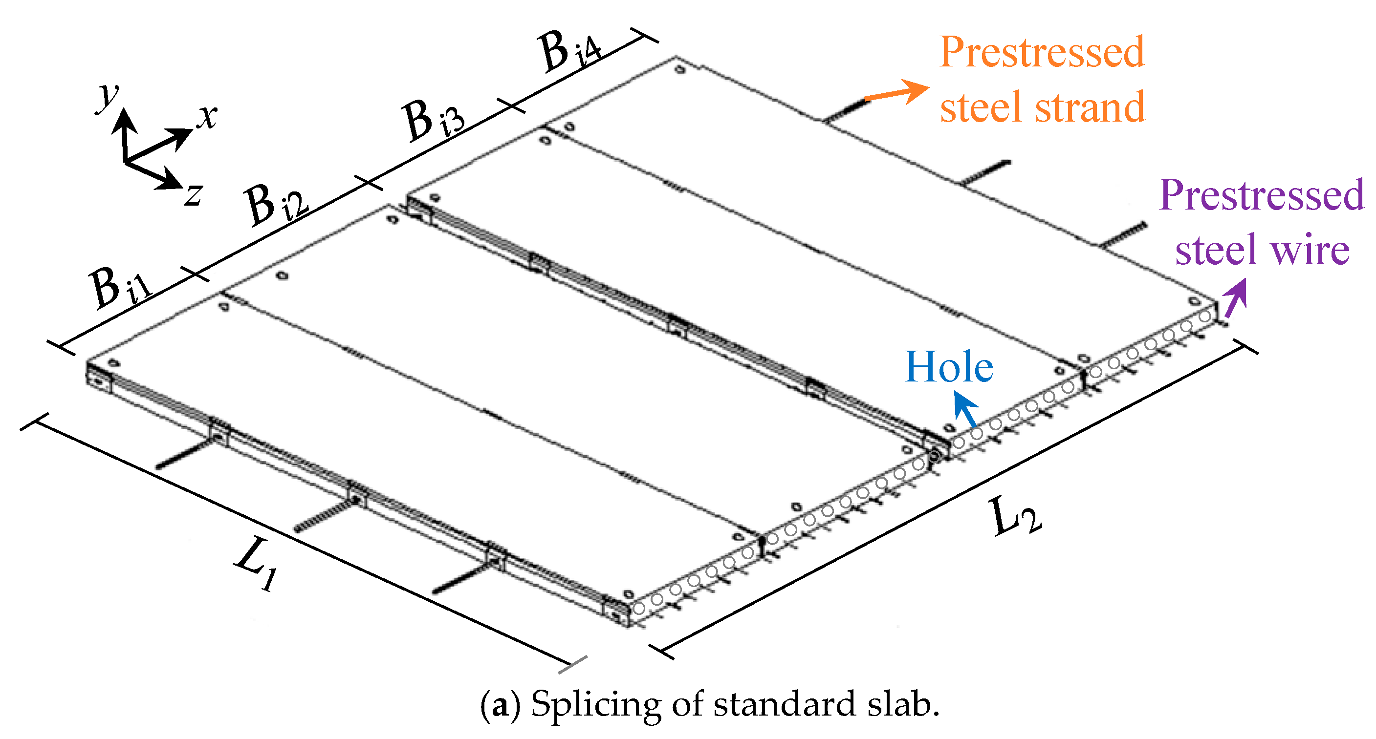
2.1. Designs of Hollow Slab
- (1)
- Firstly, the longitudinal and transverse bidirectional stressing bottom tendons are set in the shaped mold, after which the prestressing tensioning is carried out. The prestressing tendons are arranged uniformly in the transverse direction and constructed by the pretensioning method; the prestressing tendons are arranged centrally in the longitudinal direction and constructed by a post-tensioning method.
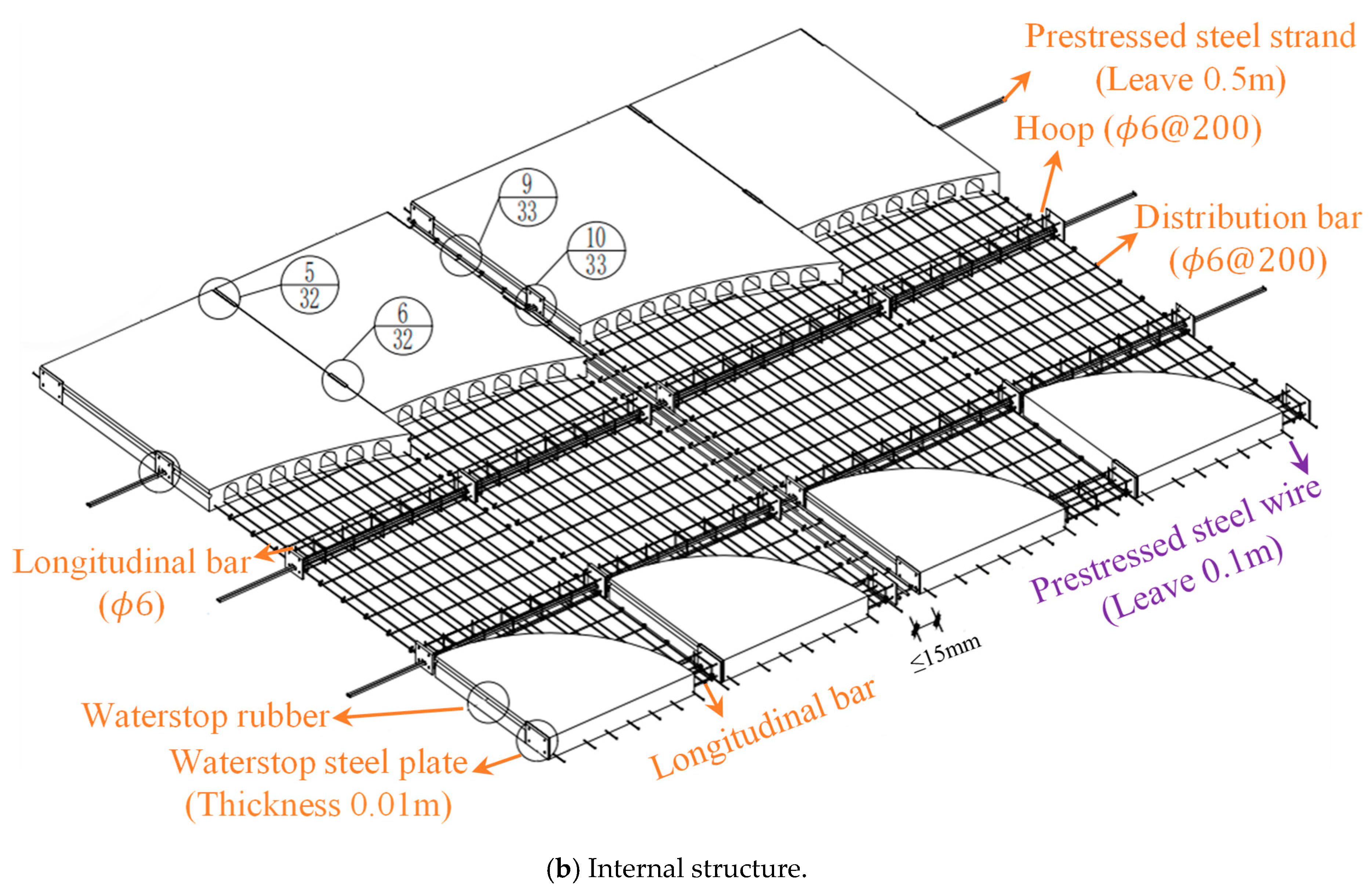
- (2)
- The circular core pipe is laid in the mold, and C40 concrete is poured afterward; then, it is vibrated densely.
- (3)
- The circular core pipe is extracted from the longitudinal mold side plate from the mold to form a longitudinal through-length empty core of concrete.
- (4)
- The piston of prefabricated C40 concrete, with a circular radius slightly smaller than the core pipe, is pushed into the longitudinal hollow core at equal distances according to the position of transverse prestressing reinforcement, so as to form transverse dense ribs to increase the transverse stiffness of the concrete slab; thus, the slab can meet the requirements of two-way force.
2.2. Theoretical Analysis
2.2.1. Designing of Internal Force Combinations
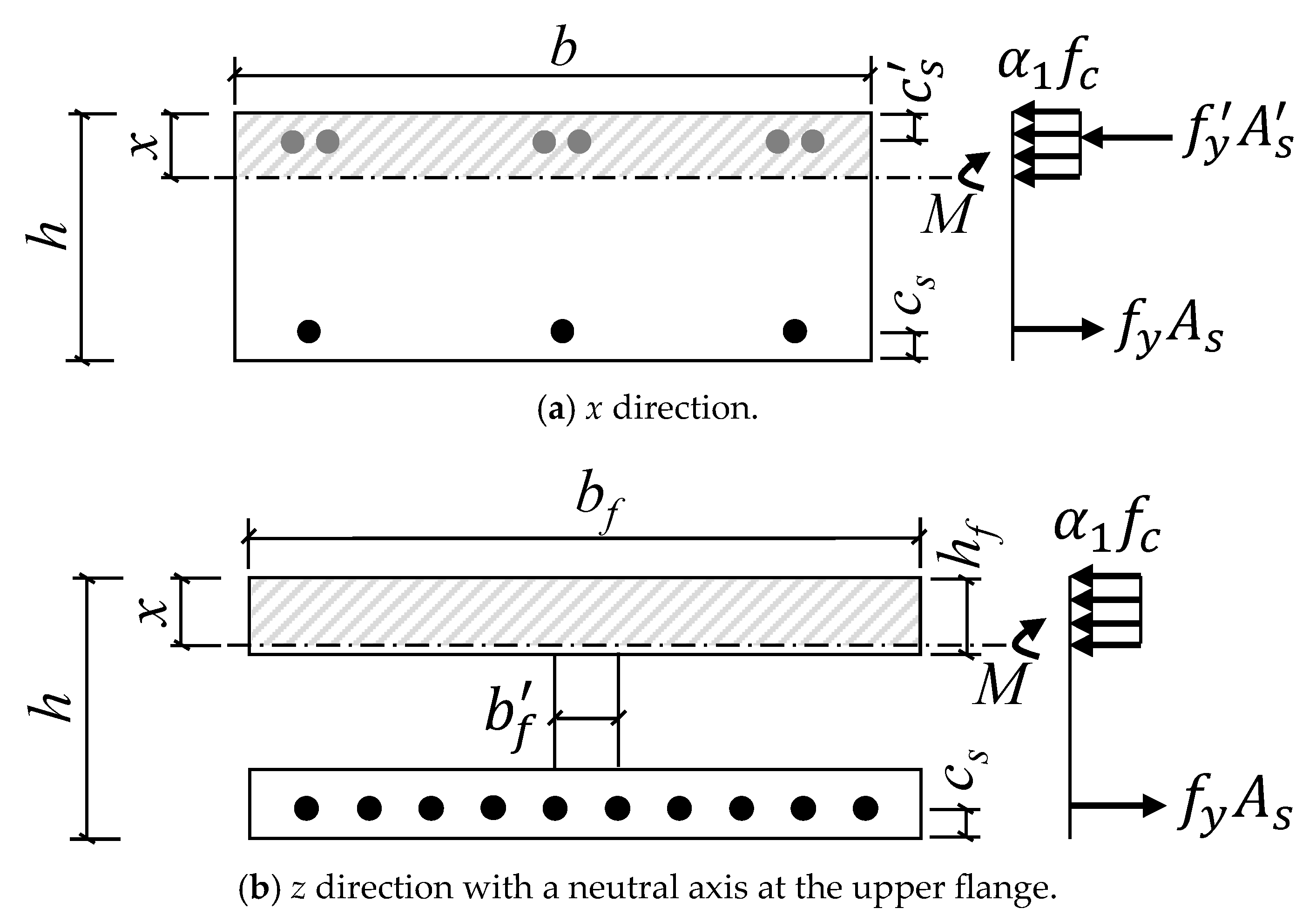
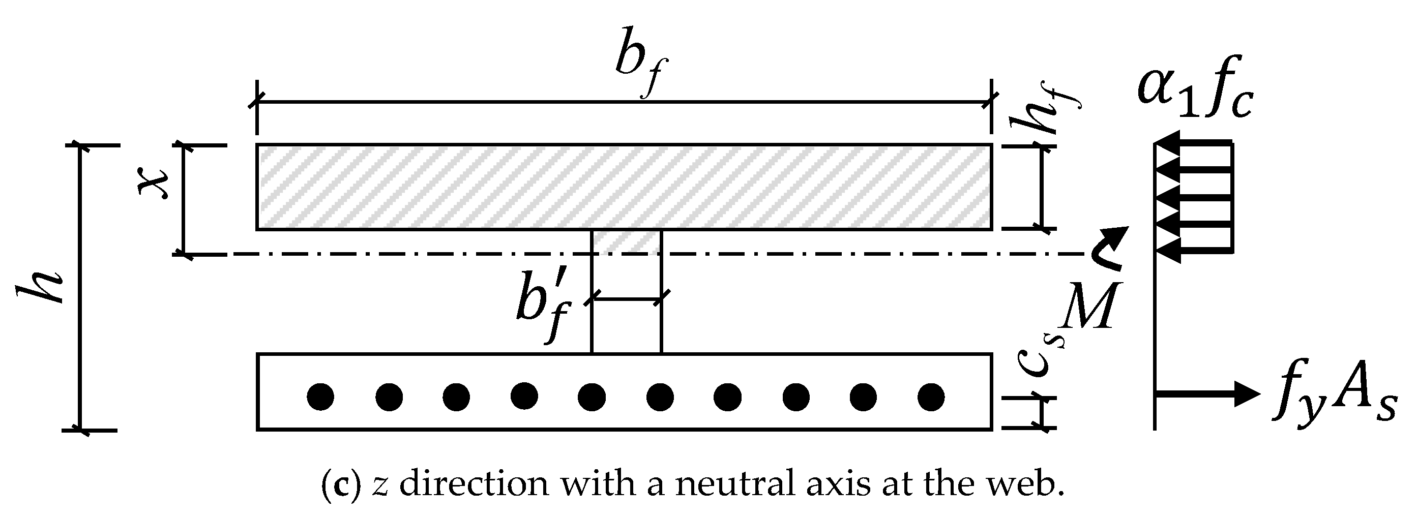
2.2.2. Bending Capacity of Normal Section
3. Experimental and Numerical Program
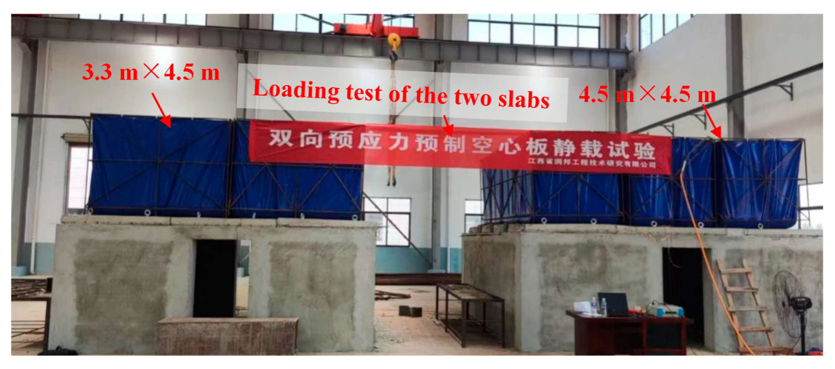
3.1. Experimental Program
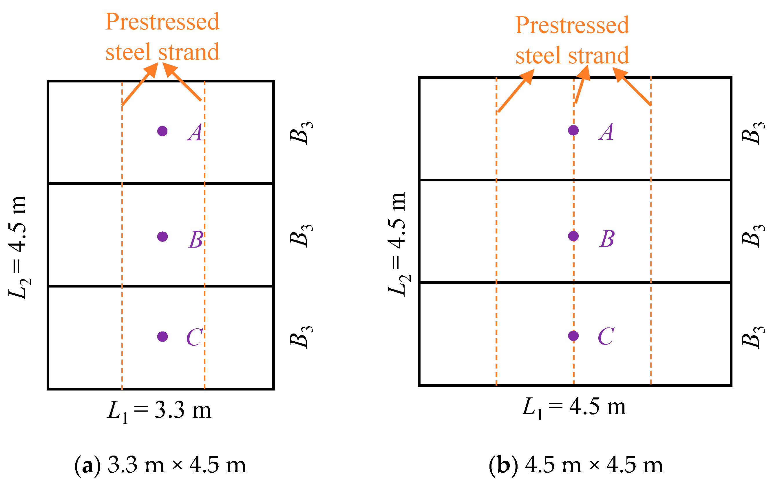
3.1.1. Testing Hollow-Core Slabs
3.1.2. Loading Scheme
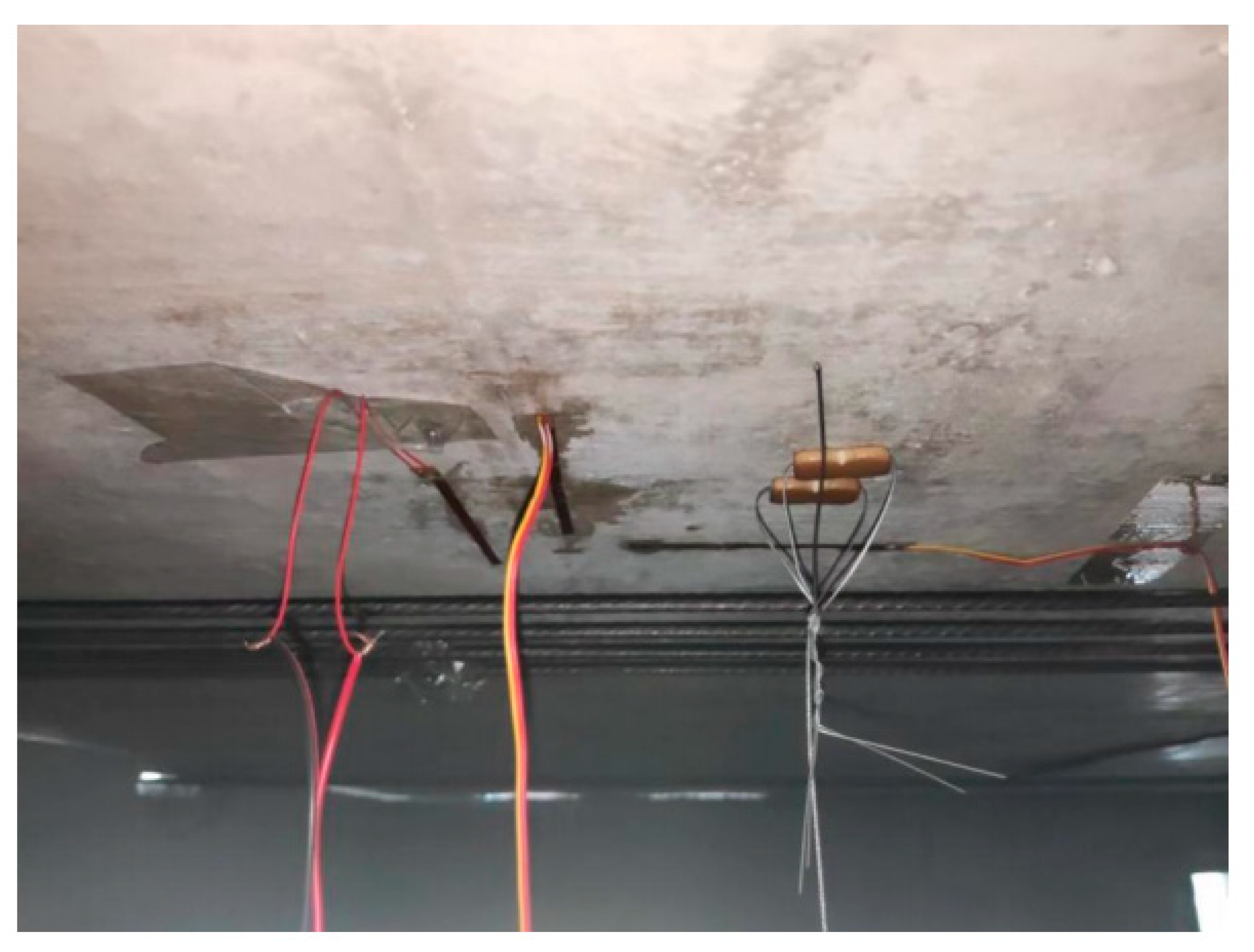
3.1.3. Measurements
3.2. Finite Element Model
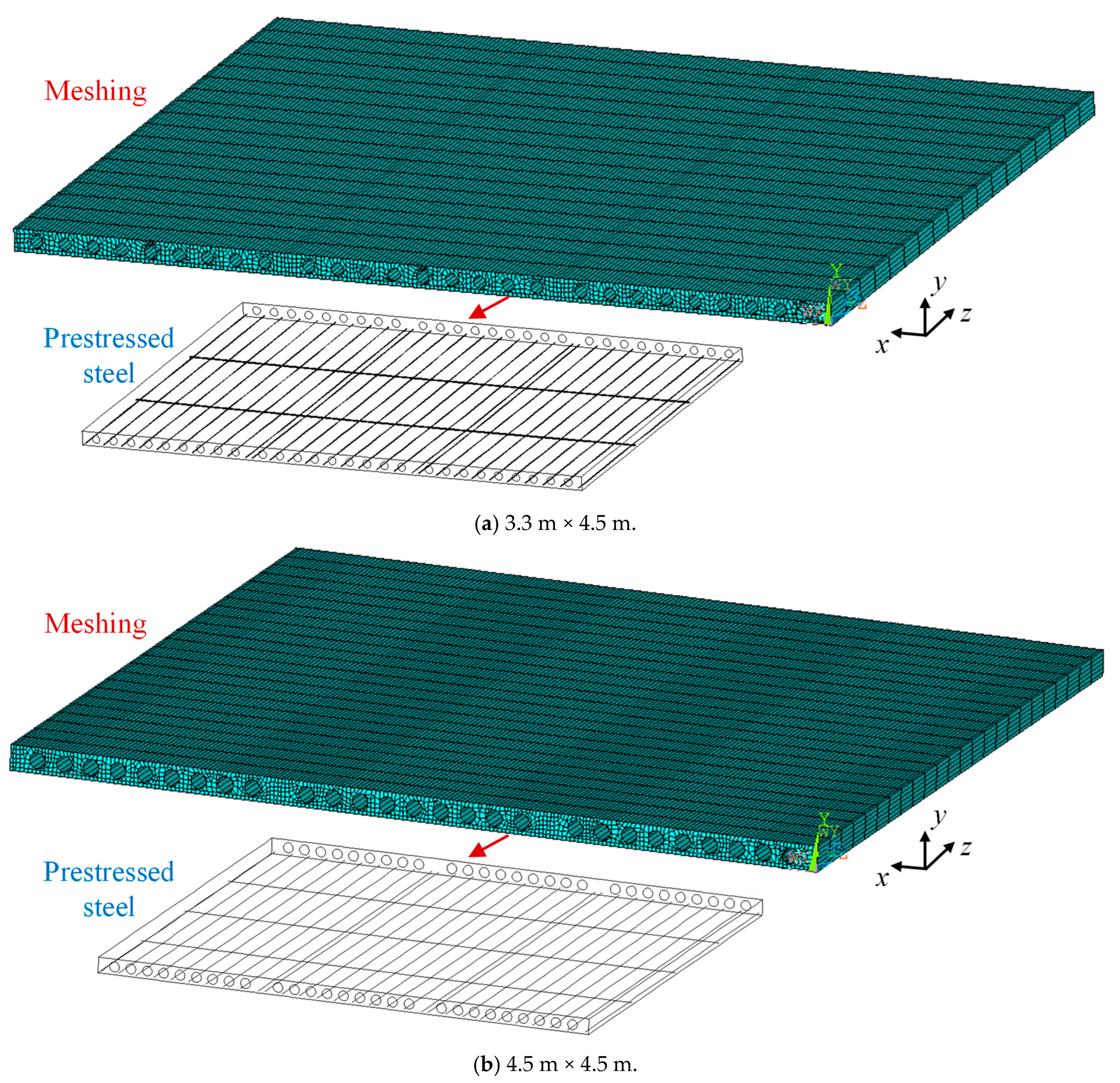
3.2.1. Modeling and Meshing
3.2.2. Concrete Model
3.2.3. Prestressing Reinforcement Model
3.2.4. Settings
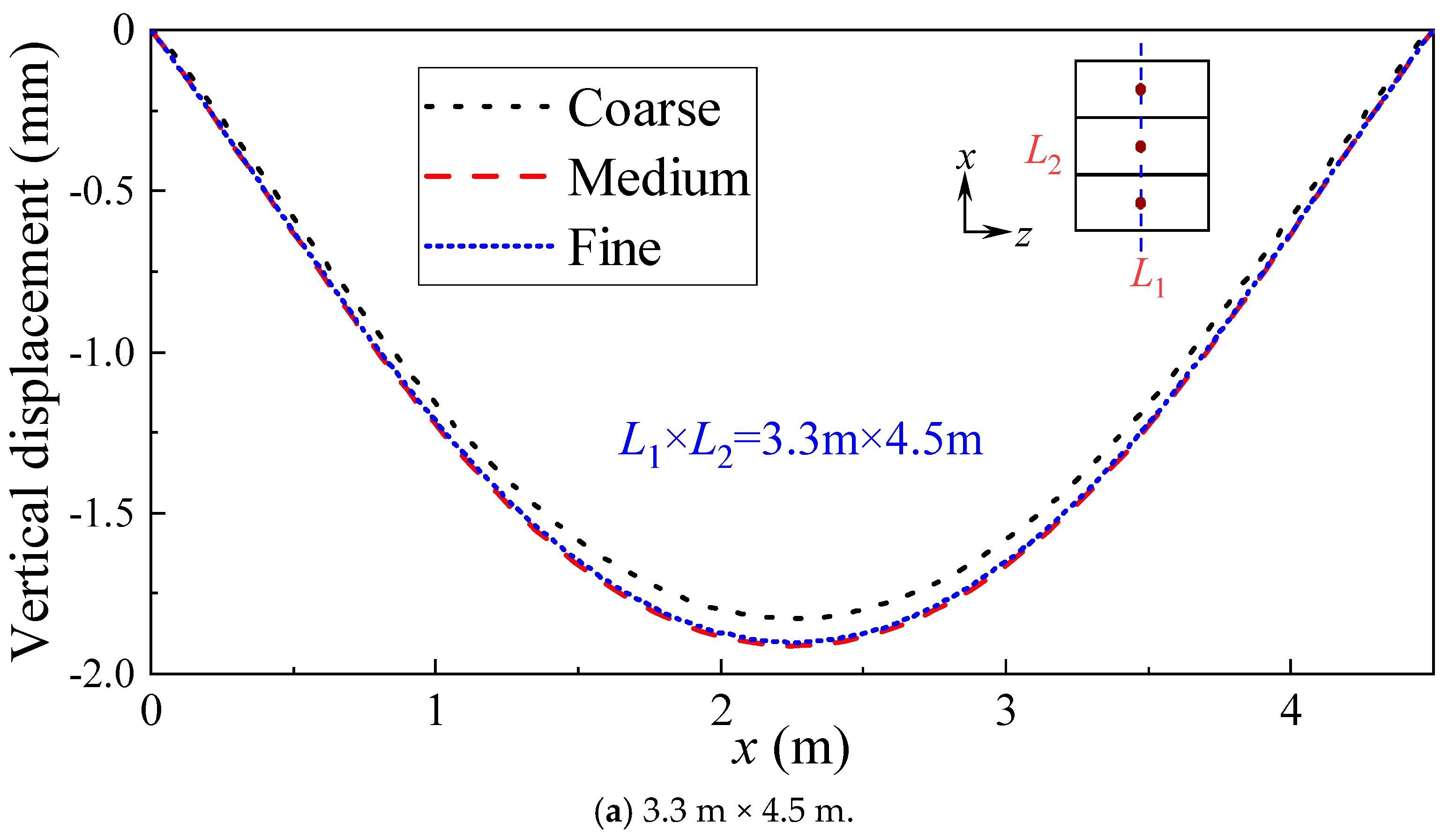
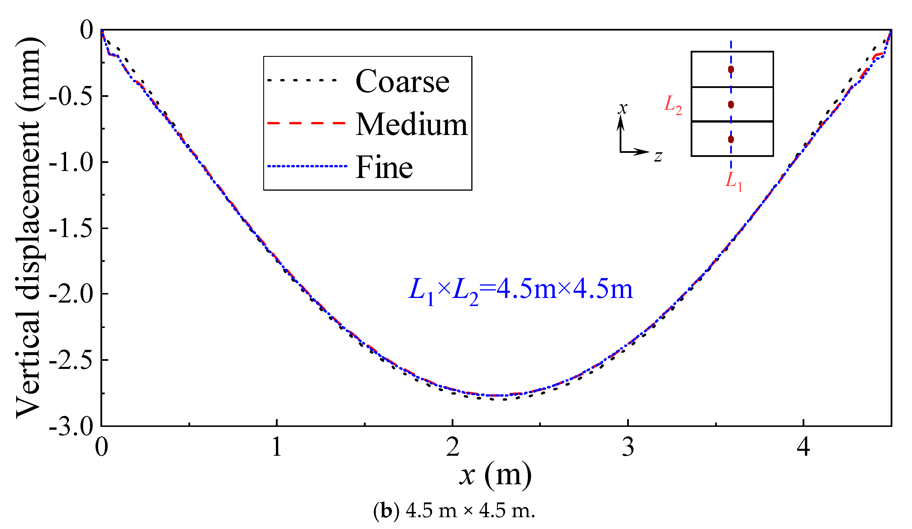
3.2.5. Grid-Independence Validation
4. Results and Discussions
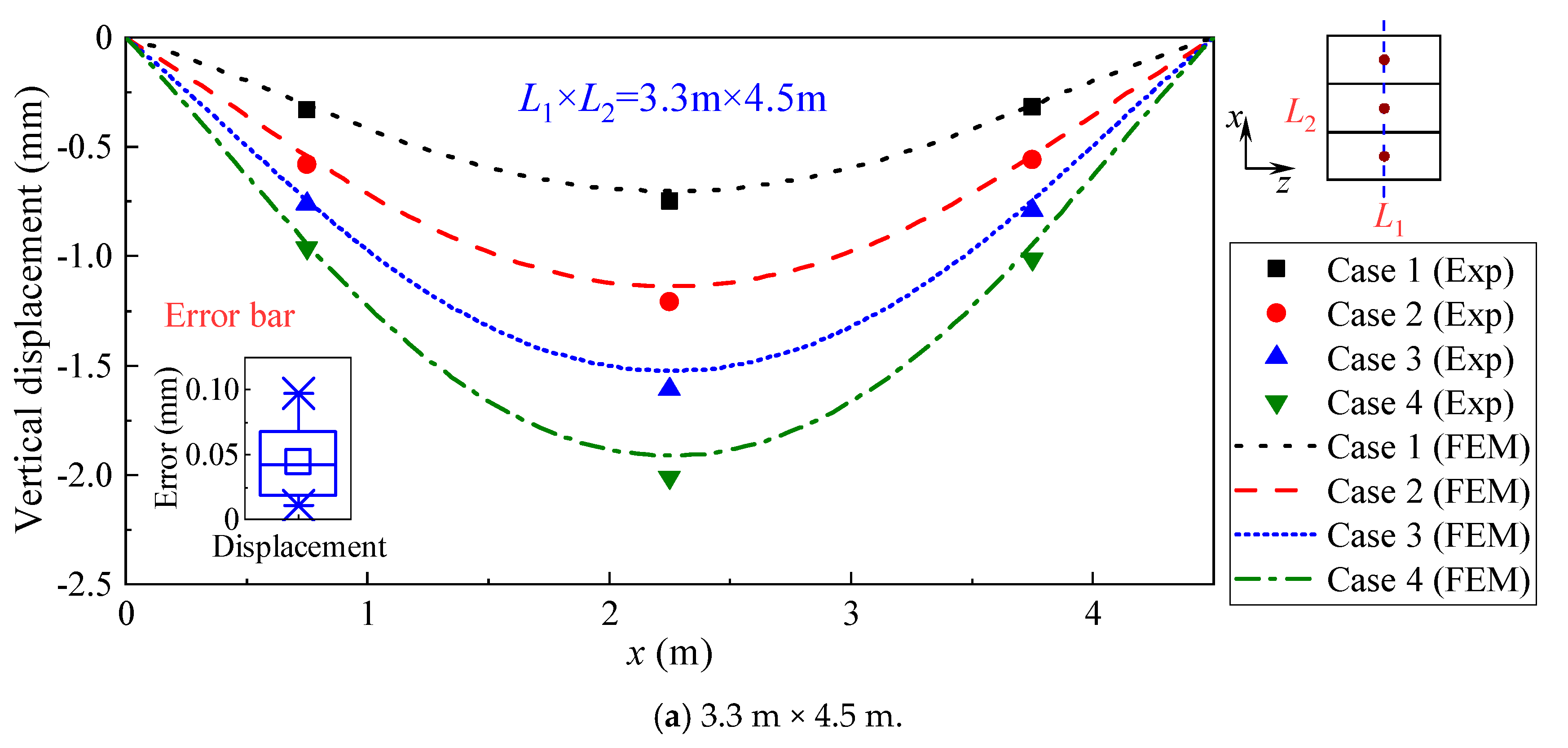
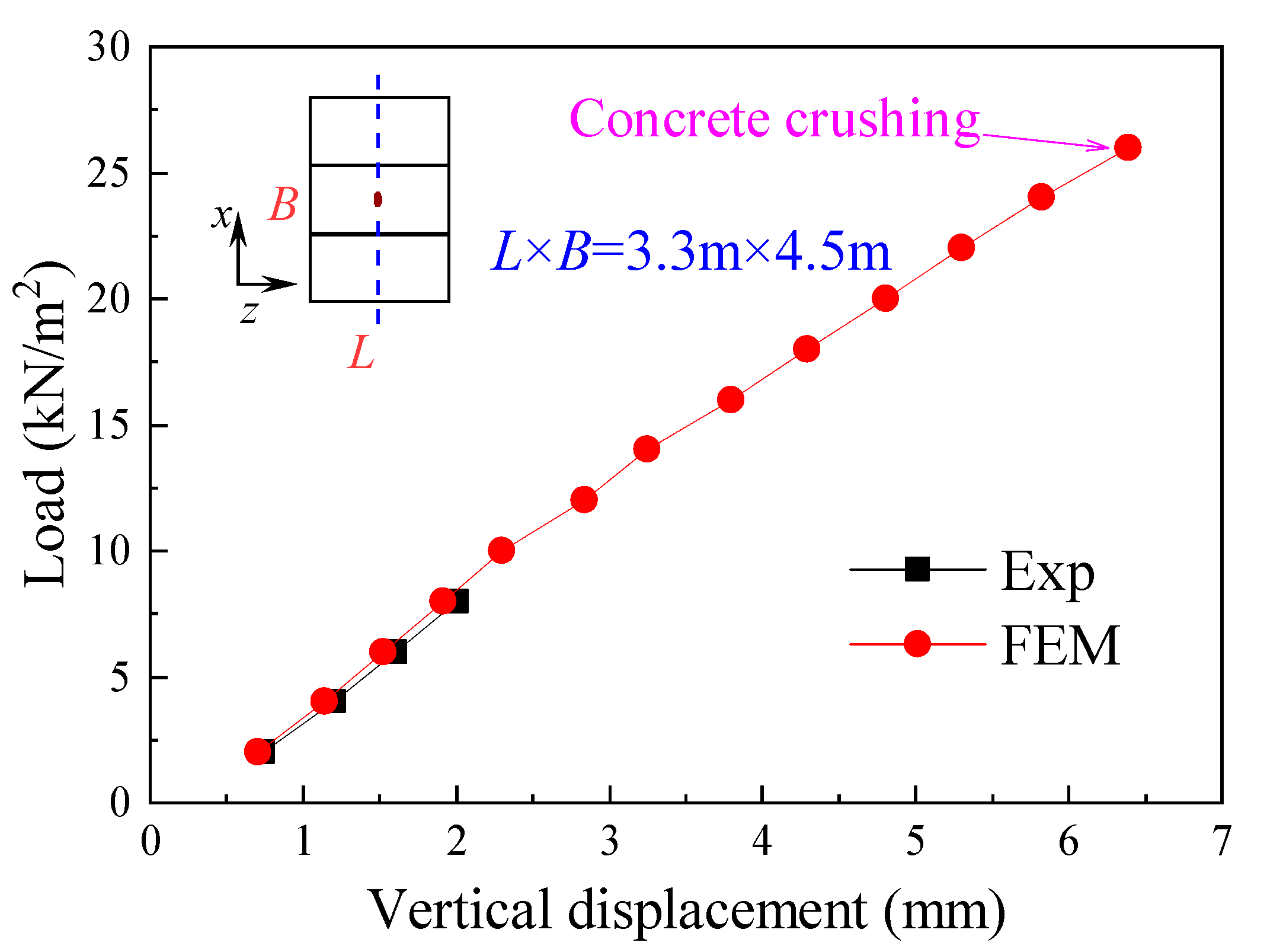
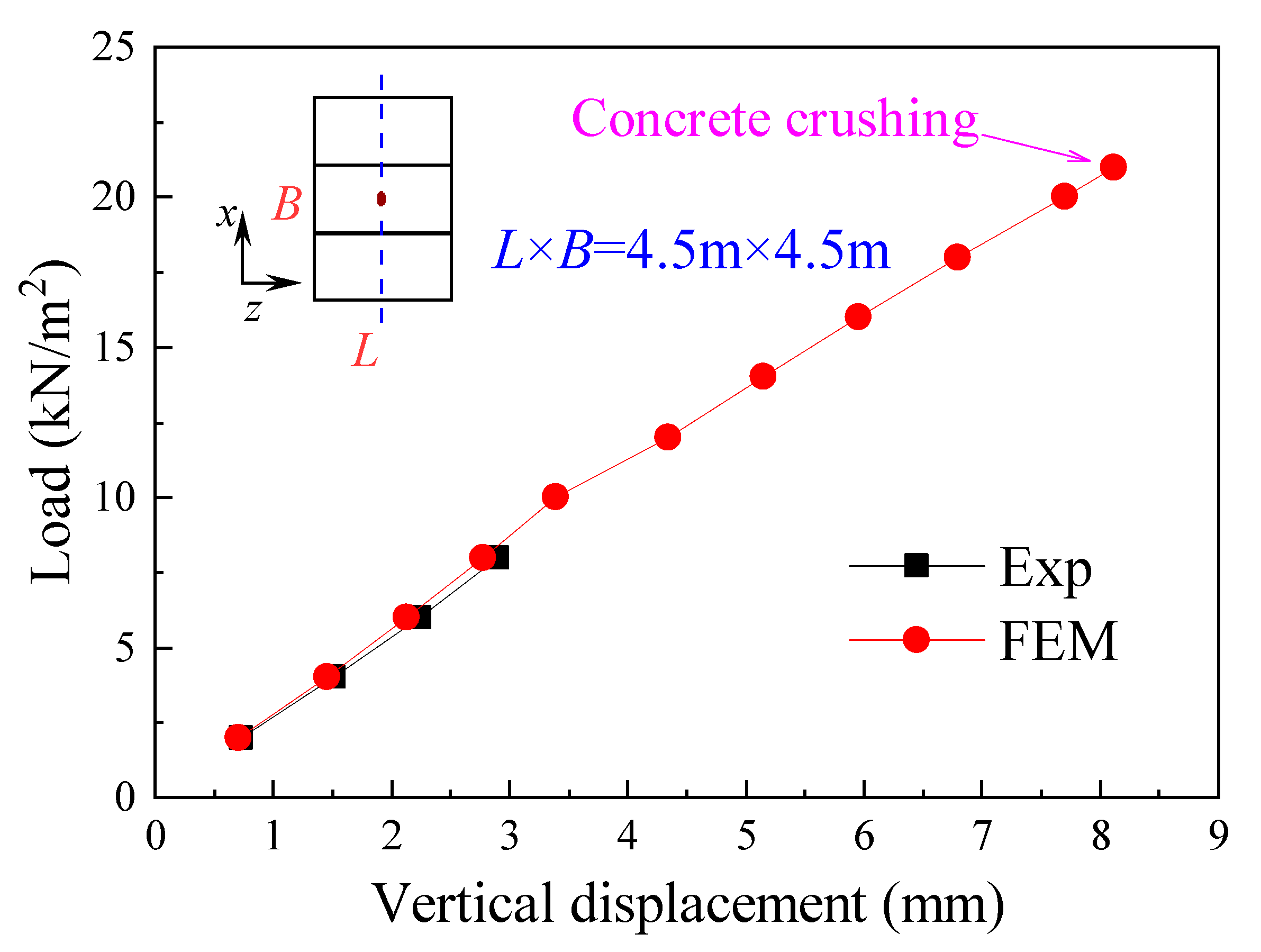
4.1. Validations for FEM Models
4.2. Analysis of Hollow-Core Slabs
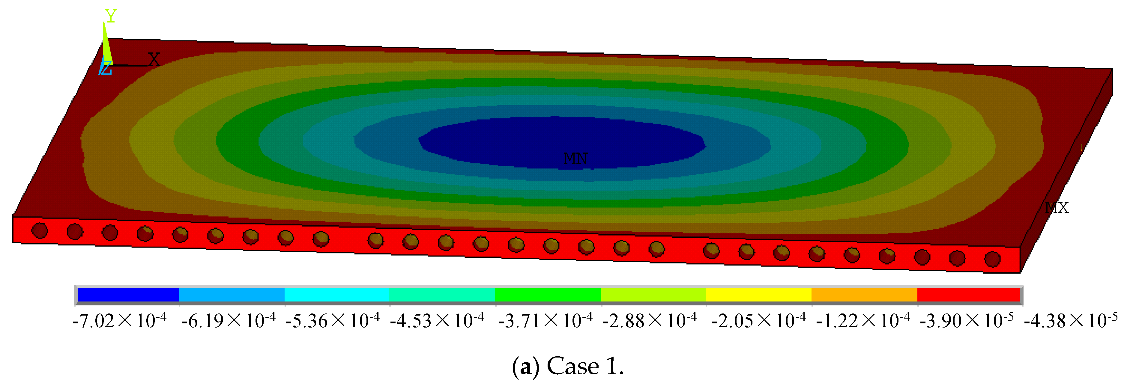
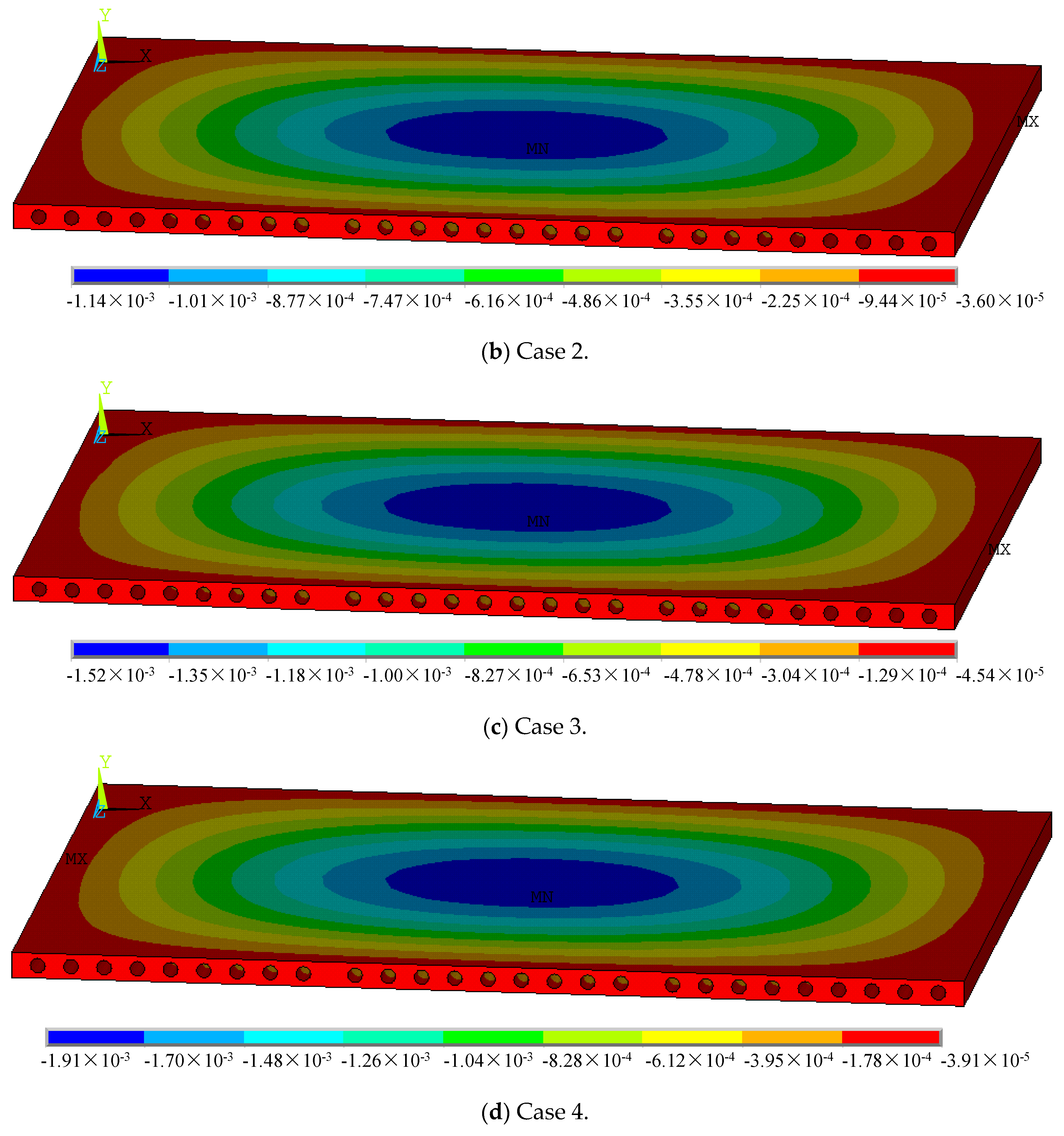
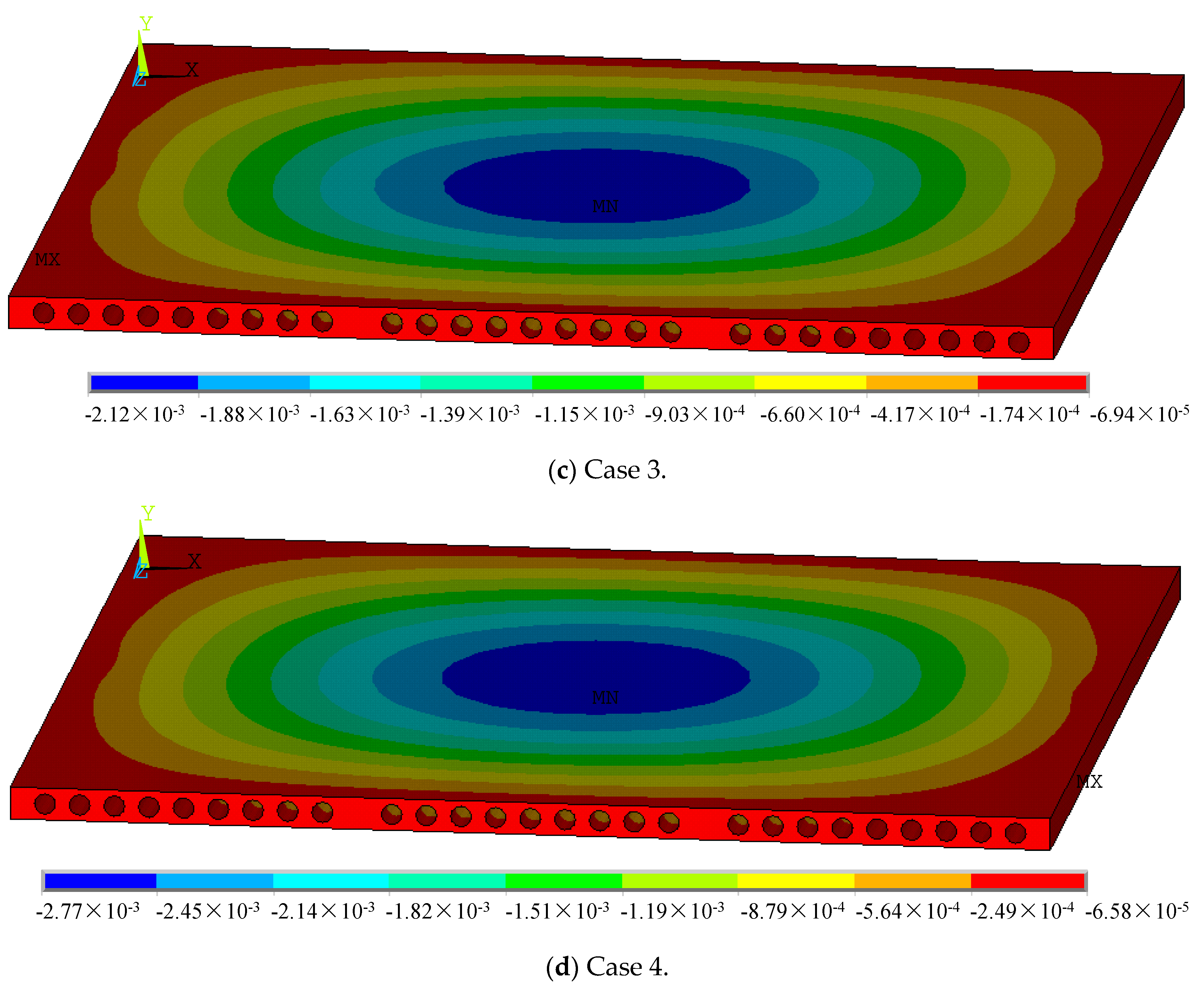
4.2.1. Deformations of Hollow-Core Slabs
- (1)
- Slab measuring 3.3 m × 4.5 m
- (2)
- Slab measuring 4.5 m × 4.5 m
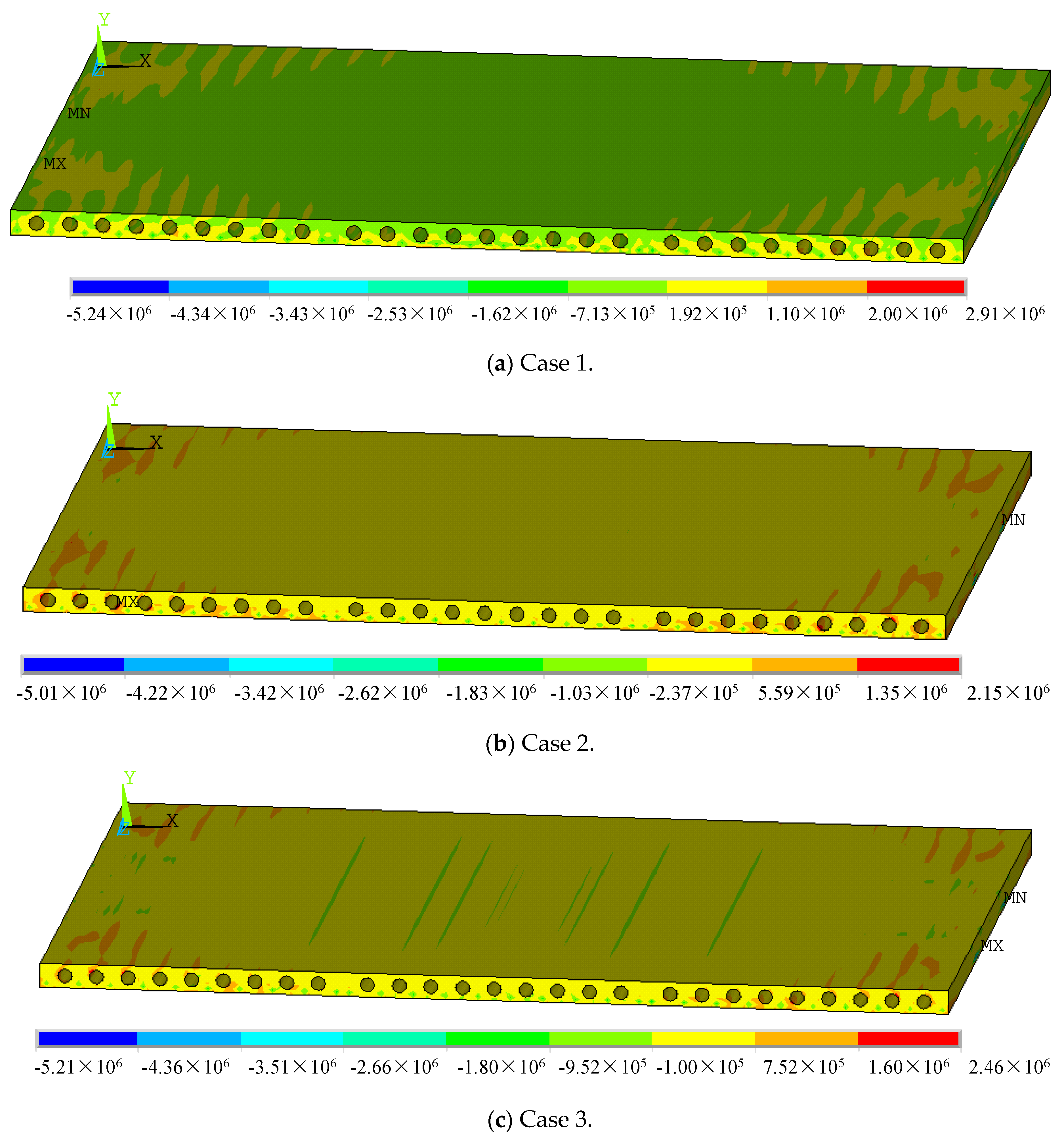
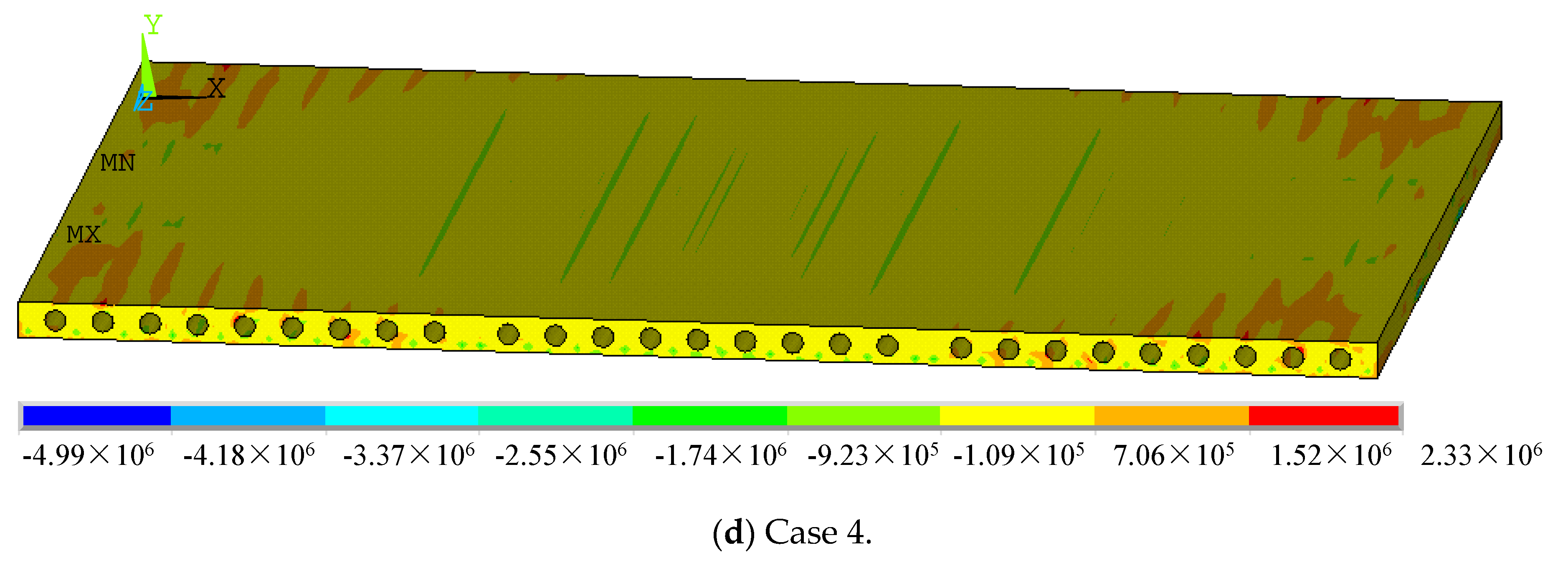
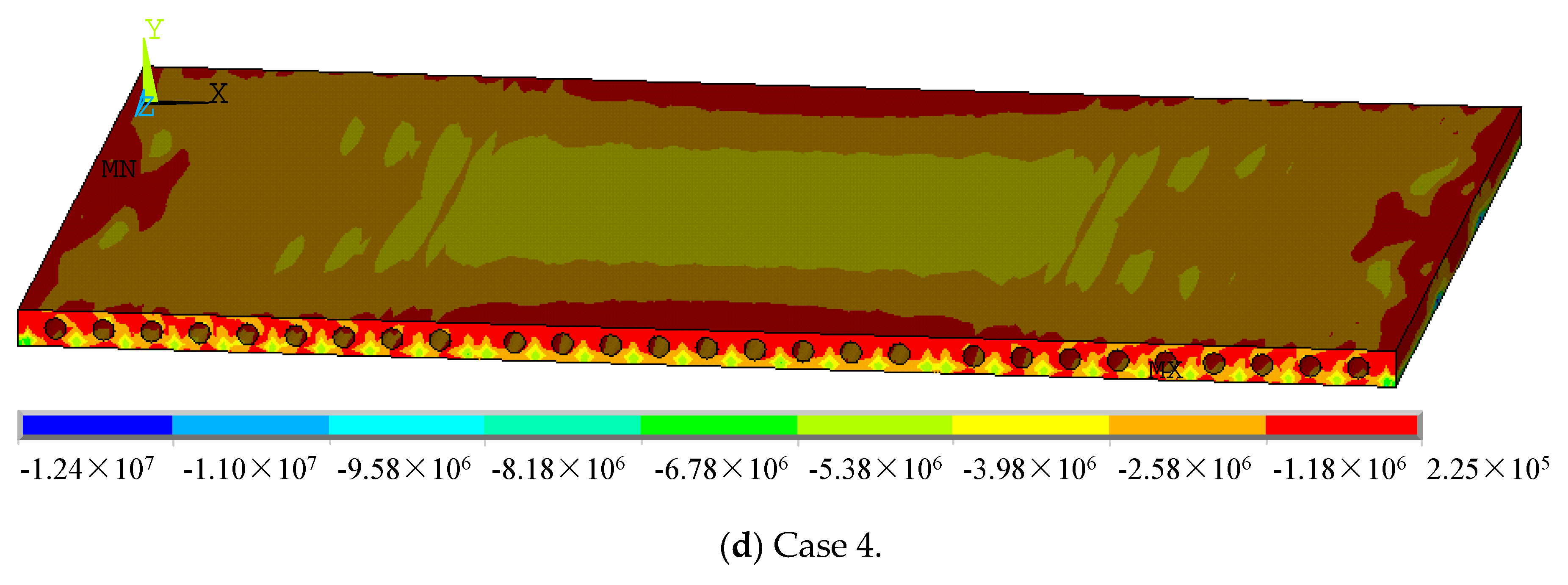
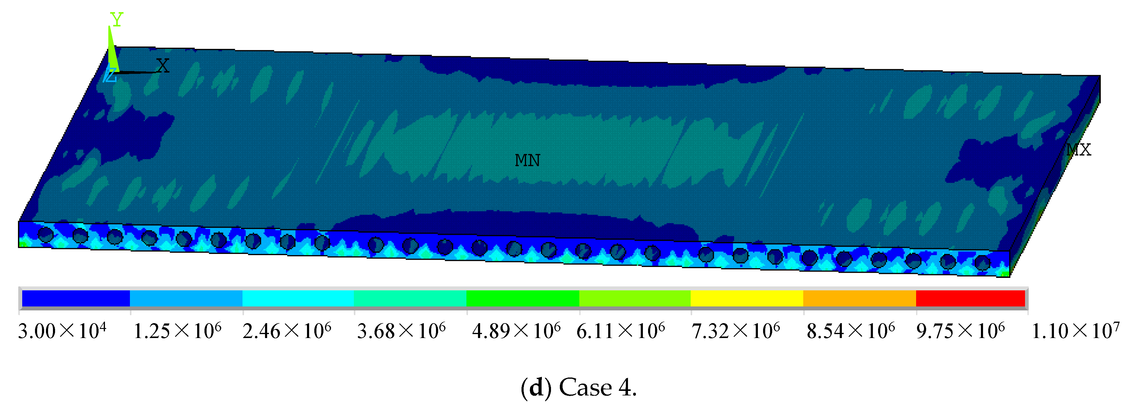
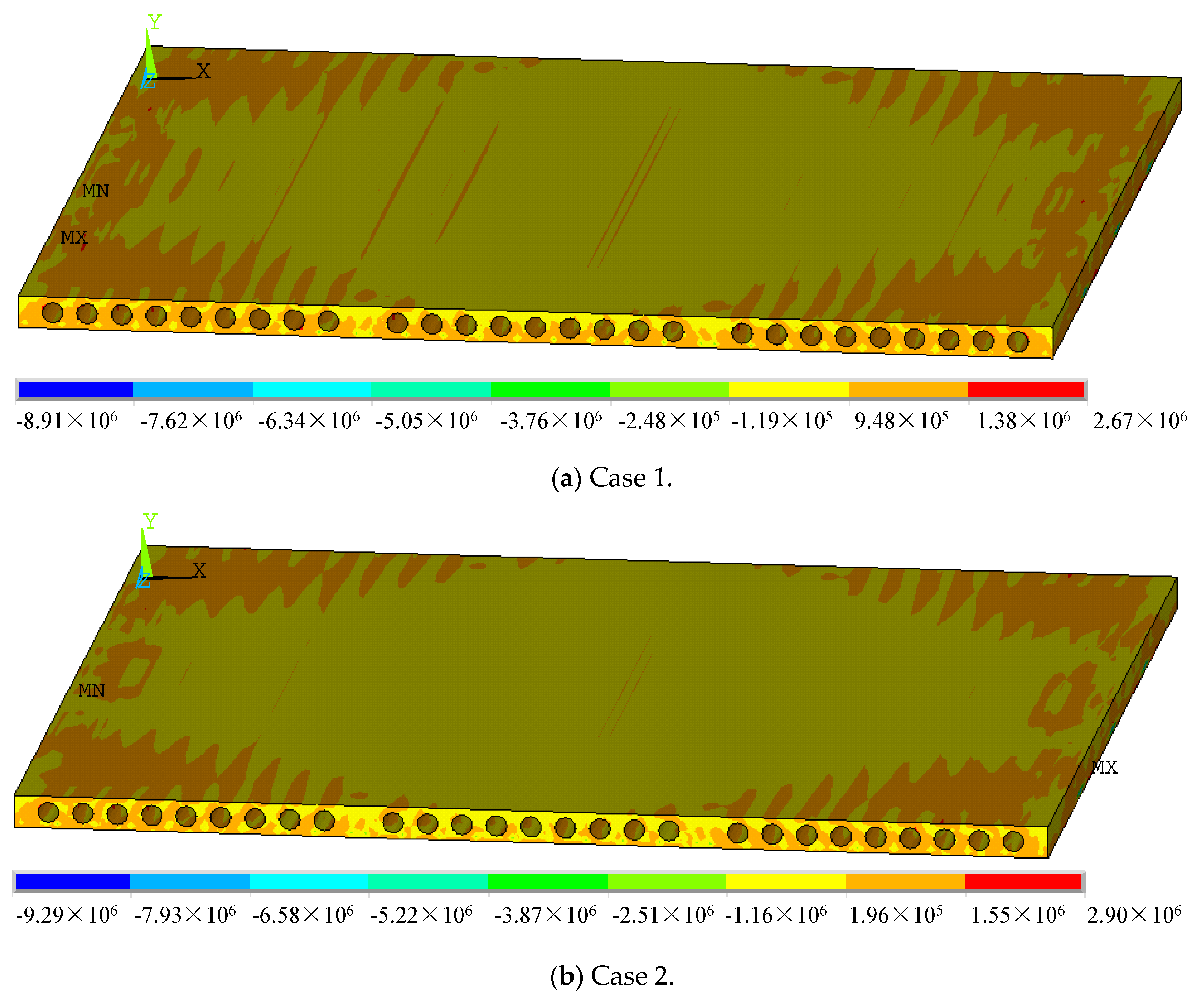
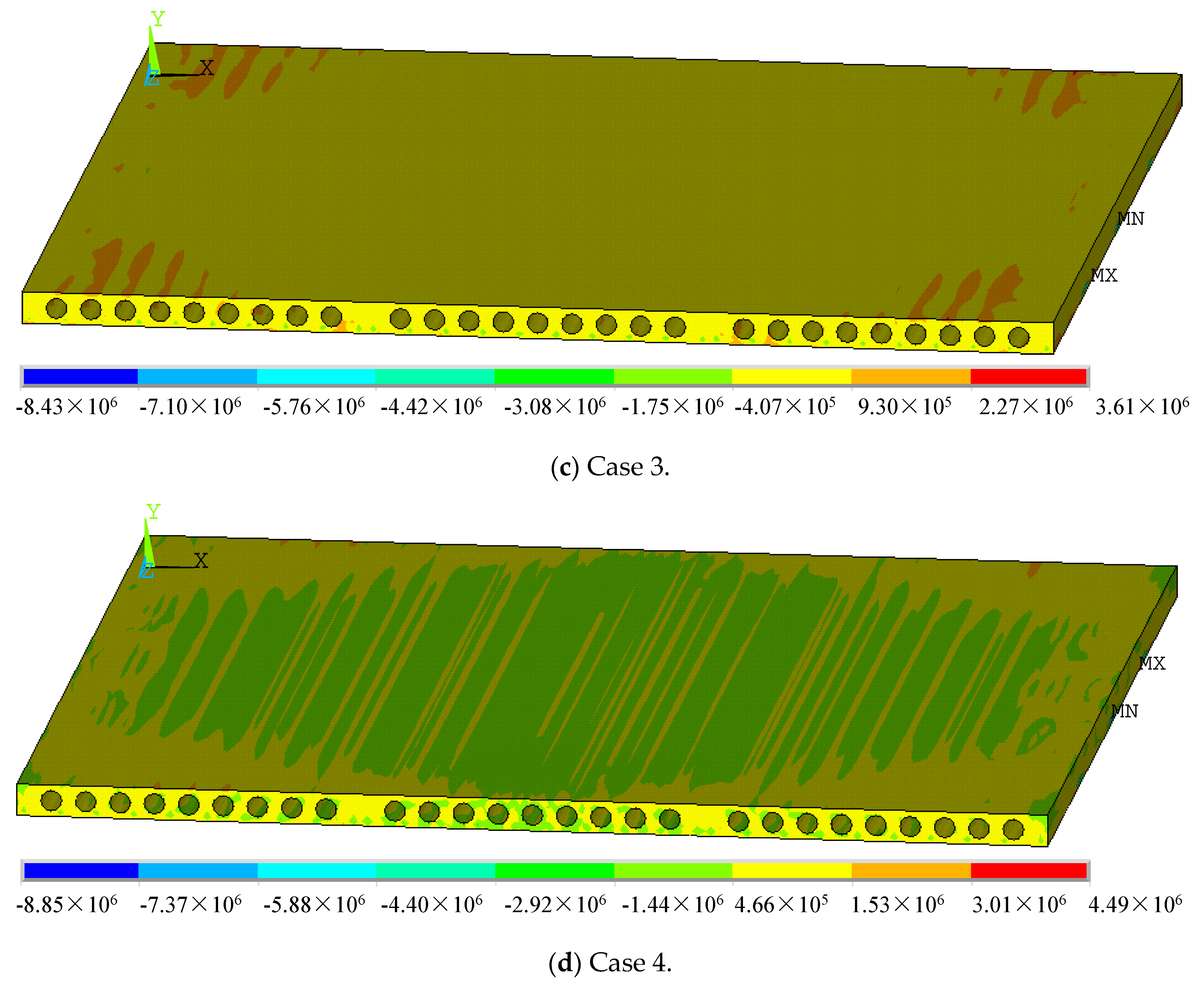
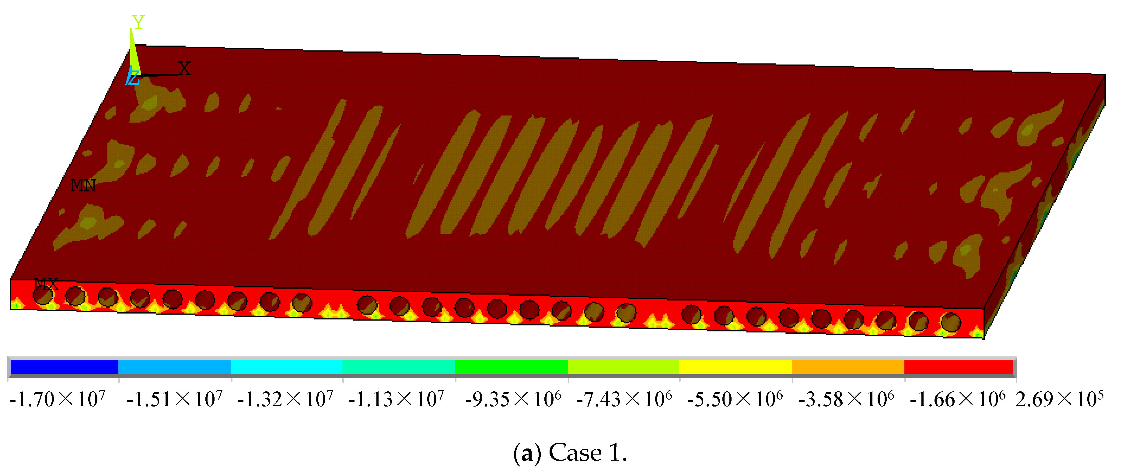
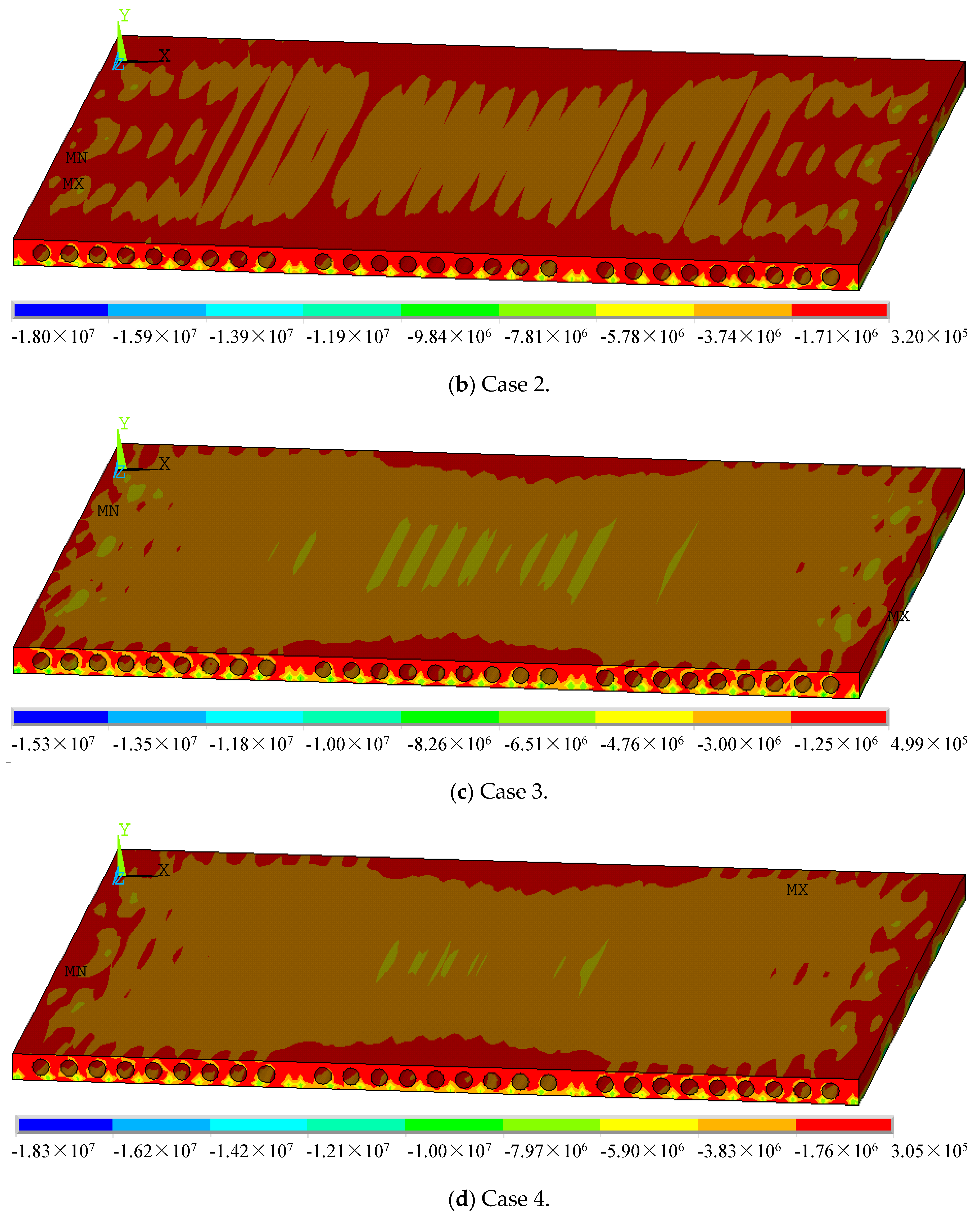
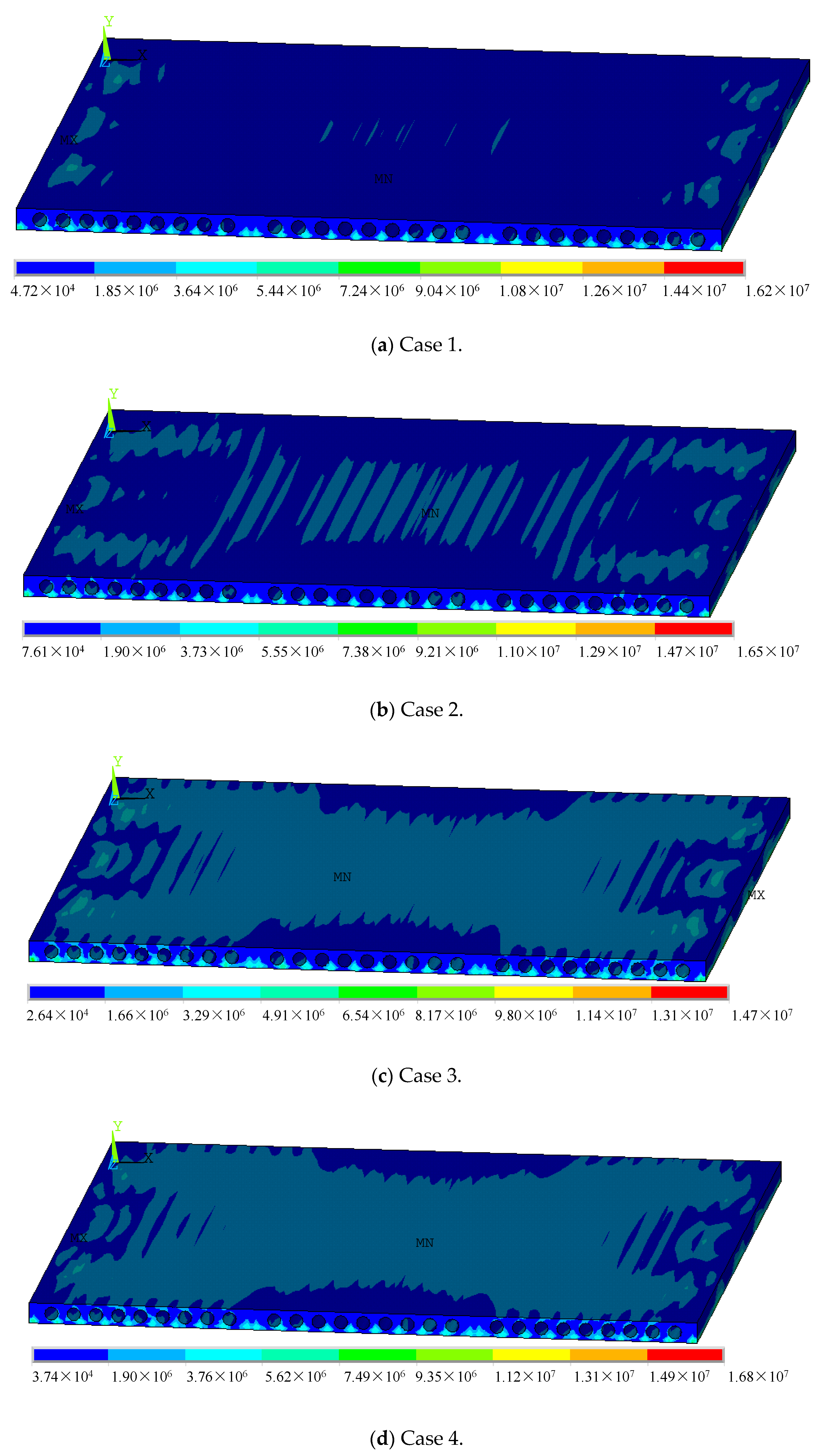
4.2.2. Stress of Hollow-Core Slabs
- (1)
- Slab measuring 3.3 m × 4.5 m
- (2)
- Slab measuring 4.5 m × 4.5 m
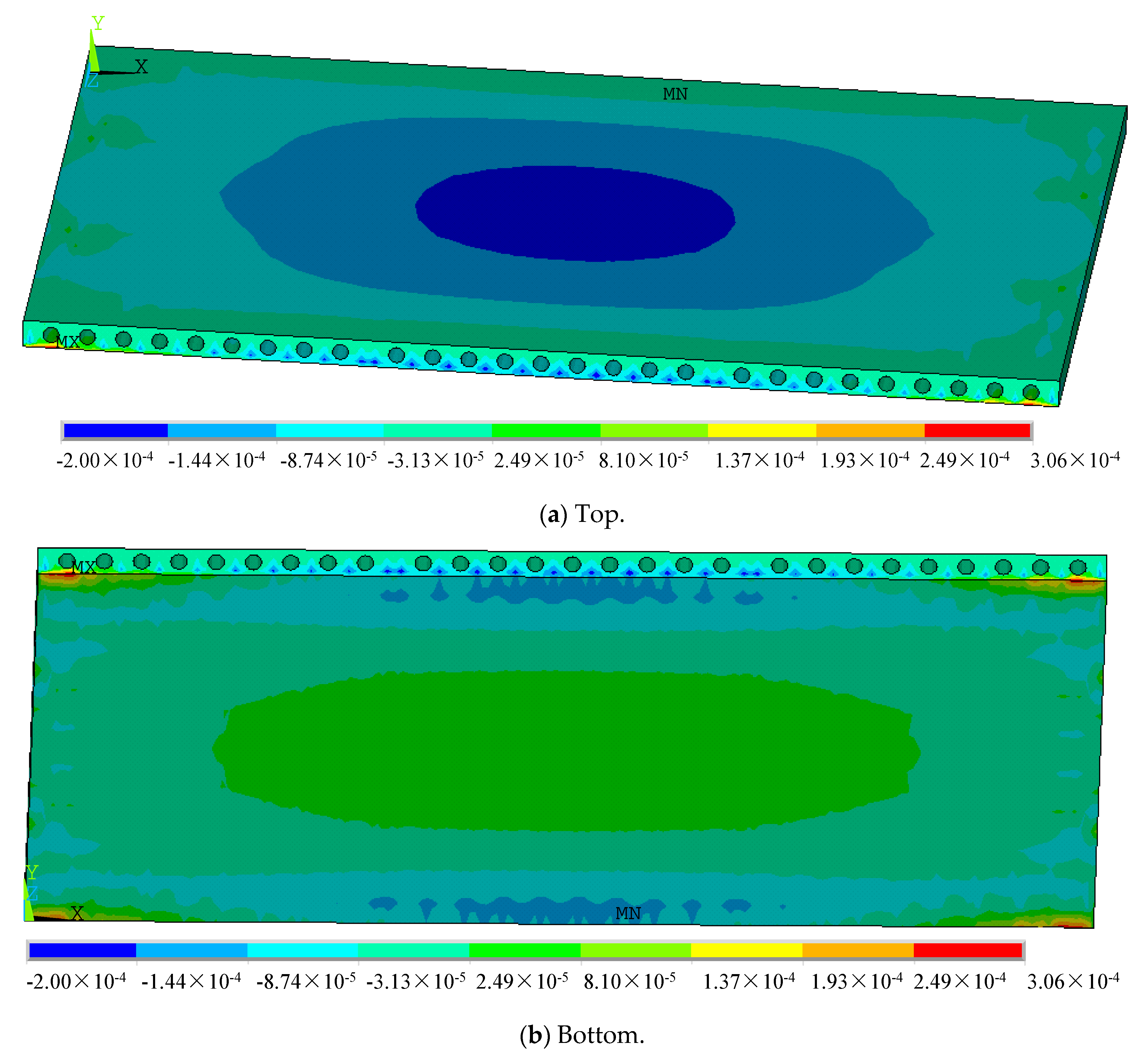
4.2.3. Strain of Hollow-Core Slabs
- (1)
- Slab measuring 3.3 m × 4.5 m
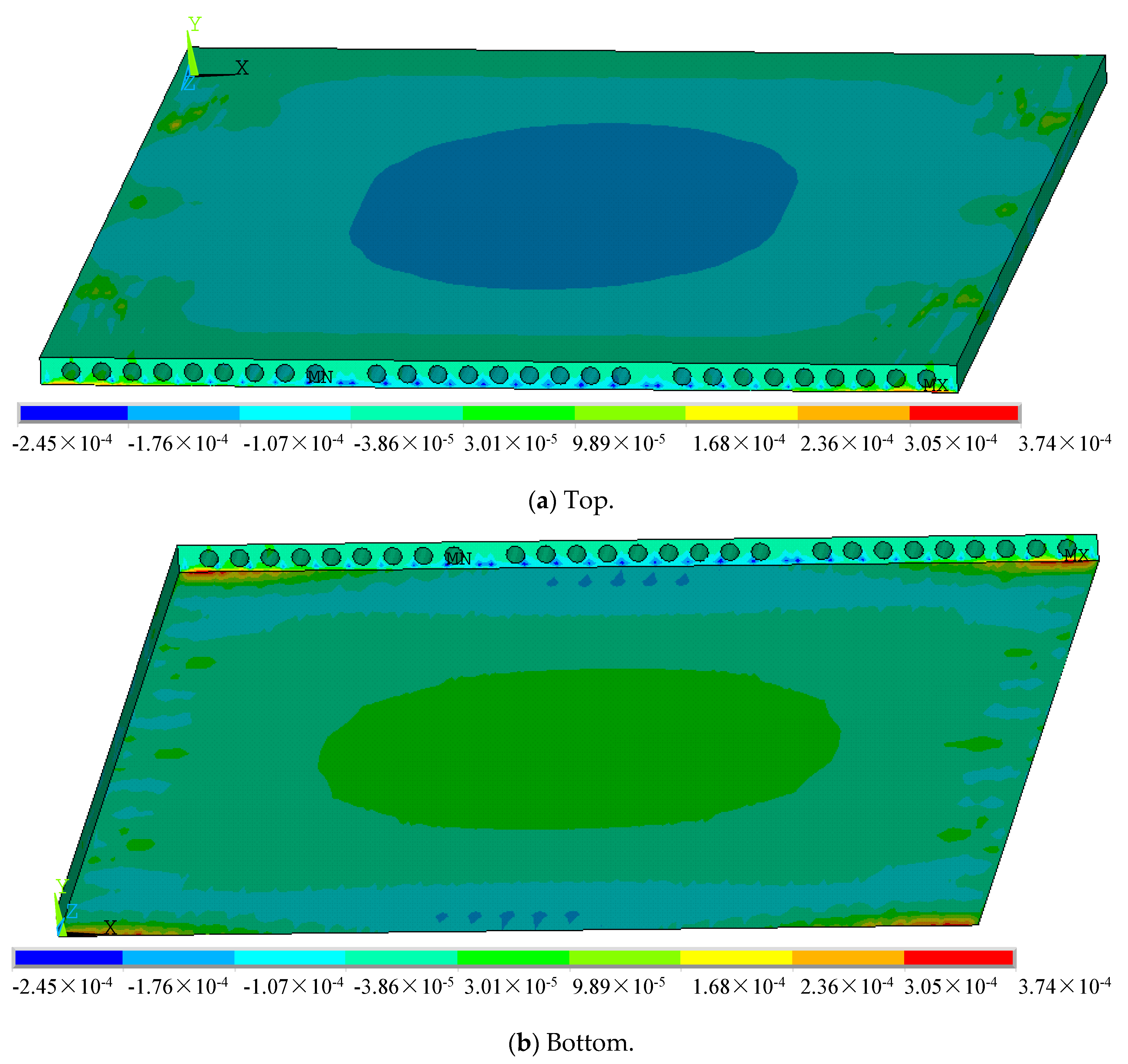
- (2)
- Slab measuring 4.5 m × 4.5 m
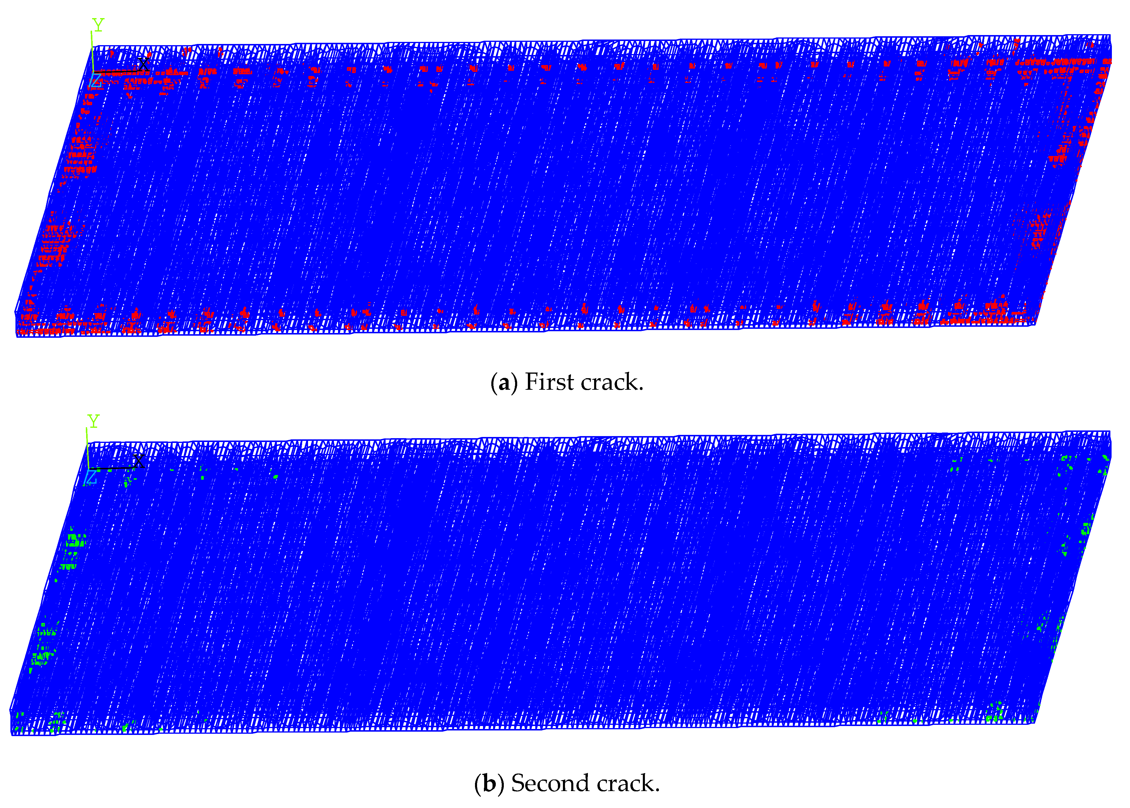
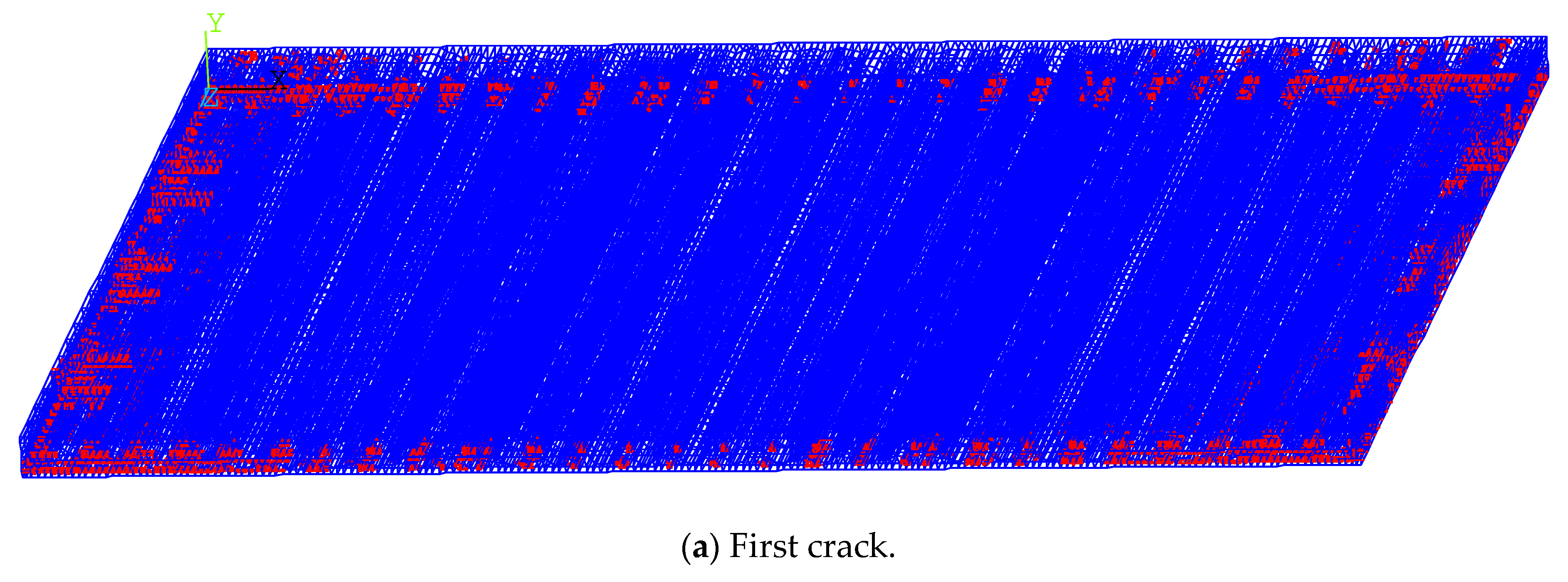
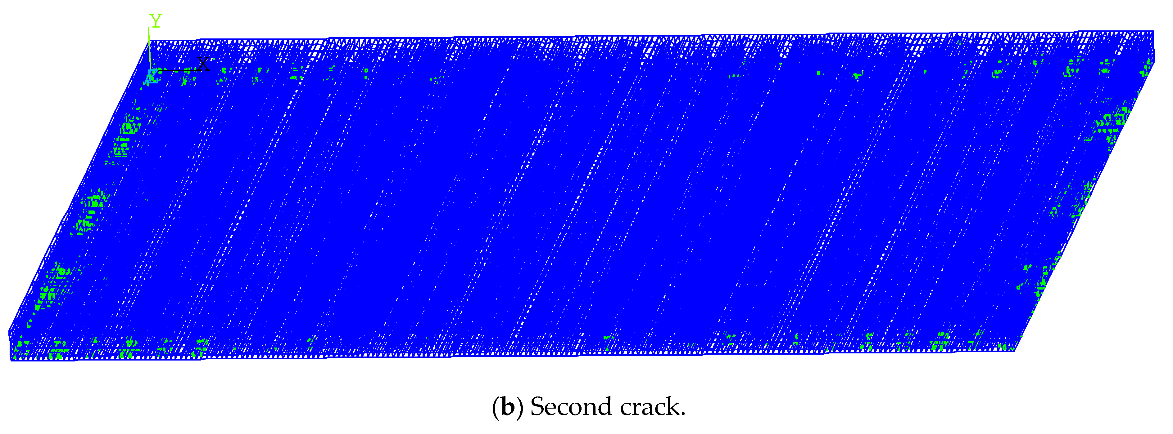
4.2.4. Cracking of Hollow-Core Slabs
- (1)
- Slab measuring 3.3. m × 4.5 m
- (2)
- Slab measuring 4.5 m × 4.5 m
5. Conclusions
- (1)
- A series of novel bidirectional, prestressed, precast hollow-core slabs based on several standard precast hollow-core slabs is proposed. The design safeguards both the bidirectional force transfer nature of the slab and the assembly properties.
- (2)
- Theoretical analysis, FEM, and experiments are conducted for two kinds of bidirectional, prestressed, precast hollow-core slabs, i.e., 3.3 m × 4.5 m and 4.5 m × 4.5 m. The mean value of the deflection prediction error for both FEM and experiments is only 0.05 mm, indicating that FEM has good accuracy and reliability.
- (3)
- The distribution of deformations, stress, and strain for the two kinds of hollow-core slabs under four loading schemes are analyzed in-depth. Moreover, the cracking processes are compared and investigated. The results show that the deflections of the proposed 3.3 m × 4.5 m and 4.5 m × 4.5 m bidirectional, prestressed, precast hollow-core slabs under the design load are less than 1.91 mm and 2.77 mm, respectively, which are less than one-third of the span, and the structural resistance performance meets the requirements.
Author Contributions
Funding
Data Availability Statement
Conflicts of Interest
Notations
| Bi | Width of standard slab, i = 1, 2, 3 corresponding to 0.9 m, 1.2 m and 1.5 m, respectively |
| L1 | Length of hollow-core slab, 2.7~6.0 m with modulus of 0.3 m |
| L2 | Width of hollow-core slab, 2.7~6.0 m with modulus of 0.3 m |
| H | Thickness of hollow-core slab, 0.12 m or 0.14 m |
| p | Number of concealed beams |
| h1 | Thickness at bottom (top) |
| h2 | Diameter of holes |
| n | Number of holes |
| b1 | Distance between hole and edge of slab |
| b2 | Distance between holes |
| dn | Distance between hole and edge of slab |
| dm | Distance between holes |
| d1 | Length of end mandrel |
| d2 | Length of middle mandrel |
| S | Load combination value |
| SGK | Standard value of uniform constant load |
| SQK | Standard value of uniform live load |
| Constant load sub-coefficient | |
| Live load sub-coefficient | |
| M1 | Designing value of the bending moment in the length direction |
| M2 | Designing value of the bending moment in the width direction |
| m1 | Bending moment coefficient for M1 |
| m2 | Bending moment coefficient for M2 |
| fc | Tensile strength of concrete |
| fy | Tensile strength of steel |
| b | Section width |
| h | Section height |
| h0 | Effective height of the cross-section |
| c | Thickness of the protective layer of concrete |
| As | Area of the tensile zone of reinforcement |
| Equivalent rectangular stress coefficient of the compression zone of the concrete | |
| Equivalent stress coefficient of the compression zone of the concrete | |
| Es | Modulus of elasticity of concrete |
| Ultimate compressive strain of concrete under non-uniform compression |
References
- Liu, Z.; Qian, J.; Zhao, Z.; Xu, Y.; Zhao, L. Static test of a simple support prestressed concrete hollow slab with two-way tube fillers. China Civ. Eng. J. 2010, 43, 40–48. [Google Scholar] [CrossRef]
- Hou, H.; Feng, M.; Qiu, C.; Lan, R.; Qu, B.; Wang, Y.; Tian, L. Experimental and theoretical study on flexural behavior of prestressed concrete composite slab with steel rib. J. Build. Struct. 2018, 39, 103–110. [Google Scholar] [CrossRef]
- Cui, S.; Liu, C.; Liu, W.; Shi, L. Research on experiment and calculating methods of flexural stiffness in direction perpendicular to separating-type joints for concrete composite slab. J. Build. Struct. 2018, 39, 75–84. [Google Scholar] [CrossRef]
- Zhong, C. A study on the application of bi-directional prestressed precast hollow core slabs in the structural construction of house buildings. Urban Resid. 2020, 27, 206–207. [Google Scholar]
- Hegger, J.; Roggendorf, T.; Kerkeni, N. Shear capacity of prestressed hollow core slabs in slim floor constructions. Eng. Struct. 2009, 31, 551–559. [Google Scholar] [CrossRef]
- Derkowski, W.; Surma, M. Complex Stress State in Prestressed Hollow Core Slabs. In Recent Advances in Civil Engineering: Building Structures; Cracow University of Technology: Kraków, Poland, 2015. [Google Scholar]
- Xun, S.; Shiping, Y.; Yuhou, Y.; Jian, F.; Litao, L. Comparative analysis of flexural performance of old full-scale hollow slab beams reinforced with fiber composites. Constr. Build. Mater. 2022, 338, 127657. [Google Scholar] [CrossRef]
- Wu, F.; Deng, L.; Liu, B.; Li, J.; Chen, S. Experimental study on four-sides simply supported single-direction-prestress double-direction-tendon concrete composite floorslab. Build. Struct. 2014, 44, 6–11. [Google Scholar] [CrossRef]
- Liu, Z.; Xia, W. Study on the shear performance of cast-in-place prestressed concrete hollow-core slabs with bi-directional fabric pipes. Railw. Eng. 2009, 5, 119–122. [Google Scholar]
- Fan, S.; Nguyen, T.N.H.; Ren, H.; Wang, P. Data-driven shear strength predictions of prestressed concrete hollow-core slabs. J. Build. Eng. 2024, 95, 110343. [Google Scholar] [CrossRef]
- Lei, Z.; Zhong, F.; Yang, C.; Tong, L.; Xu, X.; You, Y. Experimental study on the flexural resistance of existing prestressed hollow-core slab beams. Structures 2024, 63, 106323. [Google Scholar] [CrossRef]
- Li, J.; Tang, W.; Liu, J.; Hu, H.; Chen, Y.F. Negative bending behavior of prestressed hollow core slab with cast-in-place RC layer in the RC beam-slab joint area. Structures 2024, 69, 107440. [Google Scholar] [CrossRef]
- de Lima Araújo, D.; Sales, M.W.R.; Silva, R.P.M.; Antunes, C.D.F.M.; de Araújo Ferreira, M. Shear strength of prestressed 160 mm deep hollow core slabs. Eng. Struct. 2020, 218, 110723. [Google Scholar] [CrossRef]
- de Souza, J.R.; de Lima Araújo, D. Shear capacity of prestressed hollow core slabs in flexible support using computational modelling. Eng. Struct. 2022, 260, 114243. [Google Scholar] [CrossRef]
- Wang, Z.; Wang, M.; Xu, Q.; Harries, K.A.; Li, X.; Gao, R. Experimental research on prestressed concrete hollow-core slabs strengthened with externally bonded bamboo laminates. Eng. Struct. 2021, 244, 112786. [Google Scholar] [CrossRef]
- Zhang, S.; Du, S.; Ang, Y.; Lu, Z. Study on performance of prestressed concrete hollow slab beams reinforced by grouting with ultra-high performance concrete. Case Stud. Constr. Mater. 2021, 15, e00583. [Google Scholar] [CrossRef]
- Moldovan, I.-F.; Nedelcu, M.; Buru, S.-M. Analysing the Performance of Hollow Core Slabs Strengthened with CFRP. In IOP Conference Series: Materials Science and Engineering; IOP Publishing: Bristol, UK, 2021; Volume 1203, p. 32056. [Google Scholar]
- Derkowski, W.; Surma, M. Prestressed hollow core slabs for topped slim floors—Theory and research of the shear capacity. Eng. Struct. 2021, 241, 112464. [Google Scholar] [CrossRef]
- Di, J.; Sun, Y.; Yu, K.; Liu, L.; Qin, F. Experimental investigation of shear performance of existing PC hollow slab. Eng. Struct. 2020, 211, 110451. [Google Scholar] [CrossRef]
- Joo, H.E.; Han, S.J.; Kim, K.S. Analytical model for shear strength of prestressed hollow-core slabs reinforced with core-filling concrete. J. Build. Eng. 2021, 42, 102819. [Google Scholar] [CrossRef]
- Cheng, H.; Nie, K. Internal Force Calculation and Ansys Analysis of Unbondedand Bonded Prestressed Hollow Beam Mixing Two-way System Board Structure. J. Hunan Inst. Eng. 2015, 25, 83–86. [Google Scholar] [CrossRef]
- Yi, N.-H.; Lee, S.-W.; Kim, J.-W.; Kim, J.-H.J. Impact-resistant capacity and failure behavior of unbonded bi-directional PSC panels. Int. J. Impact Eng. 2014, 72, 40–55. [Google Scholar] [CrossRef]
- Nassiraei, H. Probabilistic analysis of strength in retrofitted X-Joints under tensile loading and fire conditions. Buildings 2024, 14, 2105. [Google Scholar] [CrossRef]
- Ministry of Housing and Urban-Rural Development of the People’s Republic of China. GB 50010-2010; Code for Design of Concrete Structures. China Construction Industry Press: Beijing, China, 2010. [Google Scholar]


| Width | B1 = 0.9 m | B2 = 1.2 m | B3 = 1.5 m | |||||
|---|---|---|---|---|---|---|---|---|
| Length L1 | 2.7 m 3.0 m 3.3 m | 2.7 m 3.0 m 3.3 m 3.6 m | 3.9 m 4.2 m 4.5 m 4.8 m | 5.1 m 5.4 m 5.7 m 6.0 m | 2.7 m 3.0 m 3.3 m 3.6 m | 3.9 m 4.2 m 4.5 m 4.8 m | 5.1 m 5.4 m 5.7 m 6.0 m | |
| Number of concealed beams p | 4 | 4 | 5 | 6 | 4 | 5 | 6 | |
| Height H | 0.12 m | 0.12 m | 0.14 m | 0.14 m | 0.12 m | 0.14 m | 0.14 m | |
| Thickness at bottom (top) h1 | 25 | |||||||
| Diameter of hole h2 | 0.07 m | 0.07 m | 0.09 m | 0.09 m | 0.07 m | 0.09 m | 0.09 m | |
| x direction | Number of hole n | 5 | 7 | 9 | ||||
| Distance between hole and edge of slab b1 | 0.1 m | 0.1 m | 0.105 m | 0.105 m | 0.087 m | 0.105 m | 0.105 m | |
| Distance between holes b2 | 0.0875 m | 0.085 m | 0.06 m | 0.06 m | 0.087 m | 0.06 m | 0.06 m | |
| y direction | Distance between hole and edge of slab dn | 0.2 m | ||||||
| Distance between holes dm | 0.15 m | |||||||
| Length of end mandrel d1 | 0.65 m 0.75 m 0.80 m | 0.65 m 0.75 m 0.80 m 0.95 m | 0.725 m 0.775 m 0.825 m 0.975 m | 0.775 m 0.775 m 0.925 m 0.925 m | 0.65 m 0.75 m 0.80 m 0.95 m | 0.725 m 0.775 m 0.825 m 0.975 m | 0.775 m 0.775 m 0.925 m 0.925 m | |
| Length of middle mandrel d2 | 0.70 m 0.80 m 1.00 m | 0.70 m 0.80 m 1.00 m 1.00 m | 0.80 m 0.90 m 1.00 m 1.00 m | 0.85 m 0.95 m 0.95 m 1.05 m | 0.70 m 0.80 m 1.00 m 1.00 m | 0.80 m 0.90 m 1.00 m 1.00 m | 0.85 m 0.95 m 0.95 m 1.05 m | |
| L1/L2 | m1 | m2 | L1/L2 | m1 | m2 |
|---|---|---|---|---|---|
| 0.50 | 0.0965 | 0.0174 | 0.80 | 0.0561 | 0.0334 |
| 0.55 | 0.0892 | 0.0210 | 0.85 | 0.0506 | 0.0348 |
| 0.60 | 0.0820 | 0.0242 | 0.90 | 0.0456 | 0.0358 |
| 0.65 | 0.0750 | 0.0271 | 0.95 | 0.0410 | 0.0364 |
| 0.70 | 0.0683 | 0.0296 | 1.00 | 0.0368 | 0.0368 |
| 0.75 | 0.0620 | 0.0317 |
Disclaimer/Publisher’s Note: The statements, opinions and data contained in all publications are solely those of the individual author(s) and contributor(s) and not of MDPI and/or the editor(s). MDPI and/or the editor(s) disclaim responsibility for any injury to people or property resulting from any ideas, methods, instructions or products referred to in the content. |
© 2025 by the authors. Licensee MDPI, Basel, Switzerland. This article is an open access article distributed under the terms and conditions of the Creative Commons Attribution (CC BY) license (https://creativecommons.org/licenses/by/4.0/).
Share and Cite
Jin, J.; Hu, W.; Zheng, F.; Wu, B. Experimental and Numerical Studies on the Mechanical Behavior of a Novel Bidirectional, Prestressed, Prefabricated, Composite Hollow-Core Slab. Buildings 2025, 15, 232. https://doi.org/10.3390/buildings15020232
Jin J, Hu W, Zheng F, Wu B. Experimental and Numerical Studies on the Mechanical Behavior of a Novel Bidirectional, Prestressed, Prefabricated, Composite Hollow-Core Slab. Buildings. 2025; 15(2):232. https://doi.org/10.3390/buildings15020232
Chicago/Turabian StyleJin, Junyan, Weicheng Hu, Fuyan Zheng, and Bitao Wu. 2025. "Experimental and Numerical Studies on the Mechanical Behavior of a Novel Bidirectional, Prestressed, Prefabricated, Composite Hollow-Core Slab" Buildings 15, no. 2: 232. https://doi.org/10.3390/buildings15020232
APA StyleJin, J., Hu, W., Zheng, F., & Wu, B. (2025). Experimental and Numerical Studies on the Mechanical Behavior of a Novel Bidirectional, Prestressed, Prefabricated, Composite Hollow-Core Slab. Buildings, 15(2), 232. https://doi.org/10.3390/buildings15020232