
Alternative Splicing Options for Ultra-High-Performance Concrete (UHPC) H-Piles


Abstract
1. Introduction
2. UHPC Precast Prestressed Concrete Piles
3. UHPC Pile Splicing
3.1. Evaluation of UHPC Pile Splicing Options
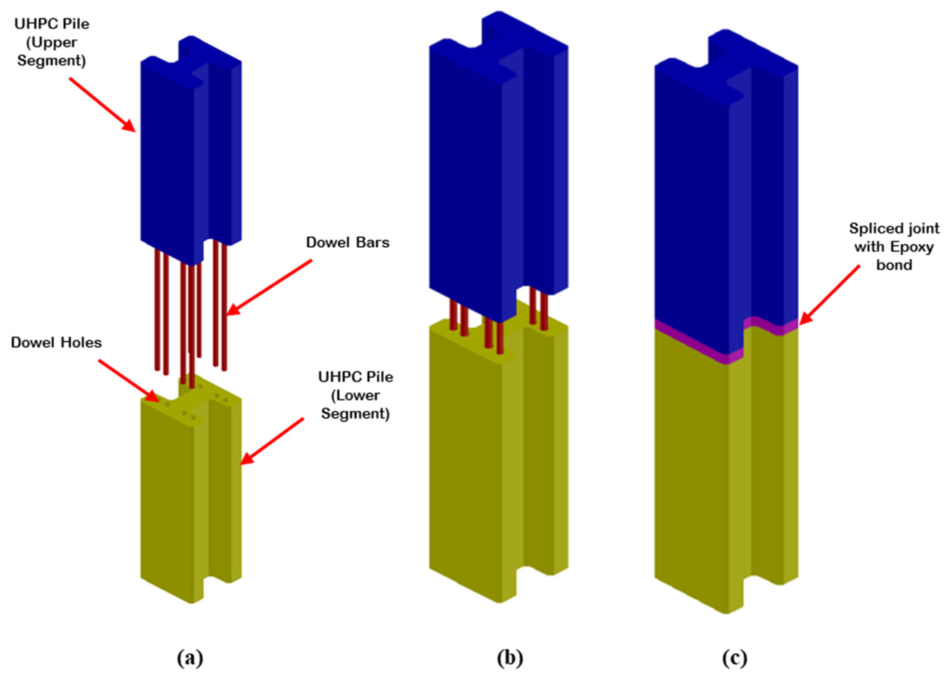
- Epoxy-bonded dowel: Epoxy-bonded dowel pile splices are commonly used in conventional precast prestressed concrete piles, especially in the state of Florida. In the dowel-type splicing method, holes are cast or drilled into the lower pile segment to receive the dowel bars from the upper segment of the pile, as illustrated in Figure 4. Dowel rebars can be made of carbon steel, stainless steel, CFRP, or GFRP bars [32,33]. The dowels must have adequate length to bond with the other pile segments [33]. Resin and cementitious grouts, as well as UHPC, can be used as fillers and bonding agents. Corrugated ducts are utilized to create holes in preplanned situations for ease of installation. During an unforeseen situation, dowel holes can be formed in the bottom pile system through coring, which necessitates a certain level of technical expertise [32].
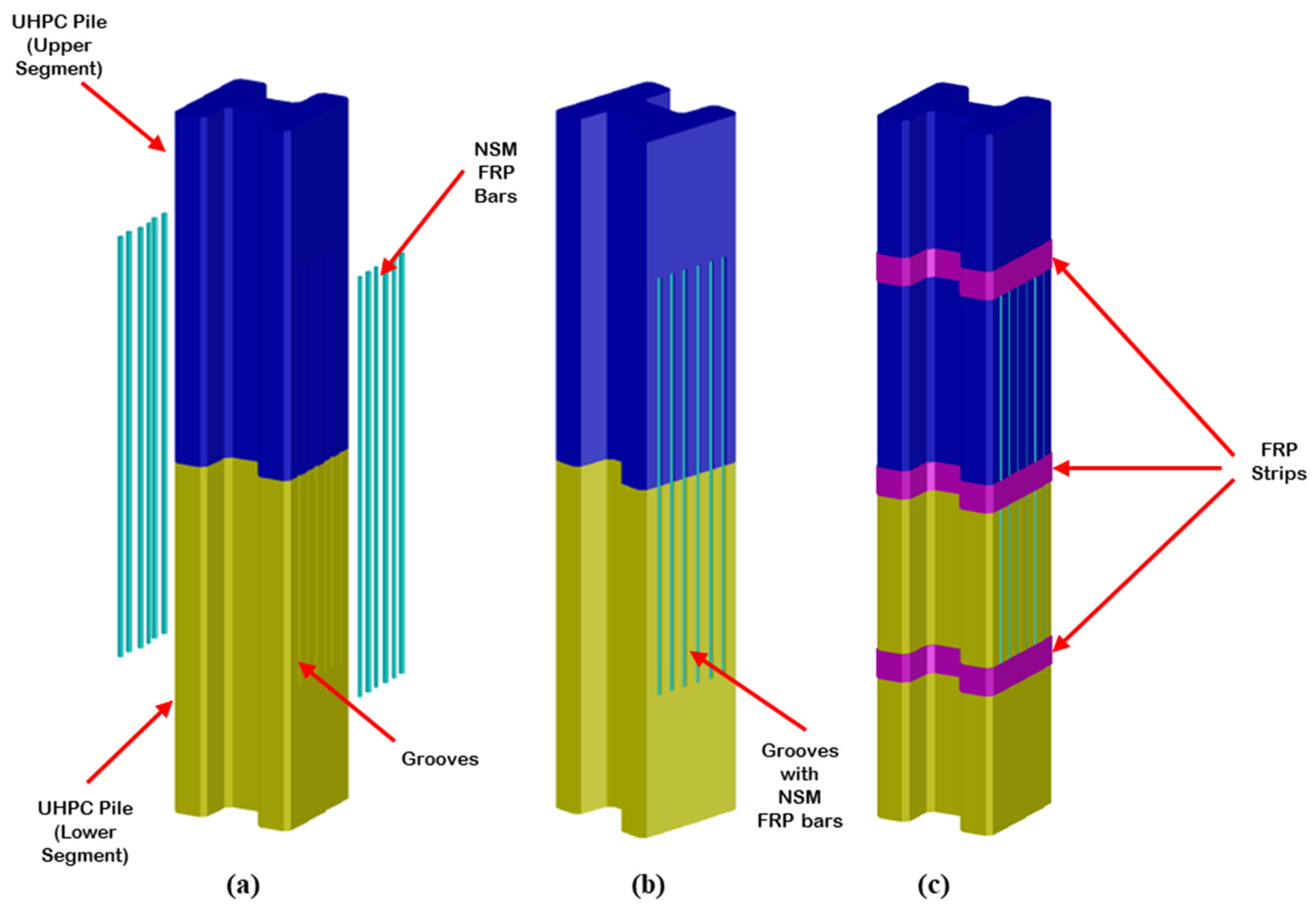
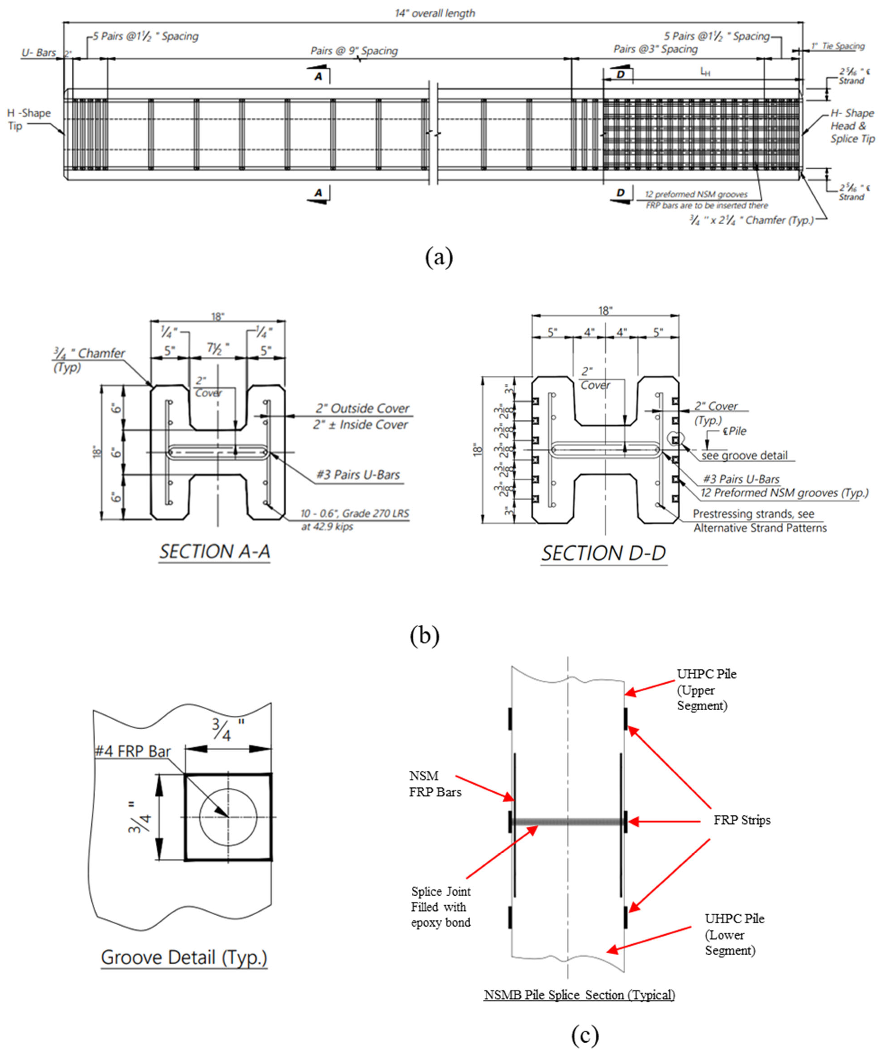
- Near-Surface-Mounted Bar (NSMB): This pile splicing method involves applying epoxy adhesives to external grooves on the concrete piles, which are then filled with FRP (or other types of) bars to connect two pile segments, as shown in Figure 5. Titanium bars have also been used as NSM bars [34]; however, because of their relatively lower strength, they do not serve the purpose of this study. An alignment bar in the form of a spar plate can be used between two pile segments to establish the connection, and FRP strips are additionally employed to reinforce the splice connection. The system can be employed in both preplanned and unplanned pile splicing situations, as the grooves can be cut in or formed during casting. The utilization of corrosion-resistant bars, such as FRP bars, enhances durability [35,36,37].
3.2. Major Features of the Proposed New UHPC Pile Splicing Options
- They offer relatively simple connection details that are labor-friendly and time-effective.
- They apply to both preplanned and unplanned construction situations.
- The use of corrosion-resistant bars as the material for NSM bars and dowel bars enhances durability and corrosion resistance, resulting in improved performance in corrosive environments such as marine areas.
- If designed properly, the connection guarantees the structural performance and the efficiency of the connected precast prestressed UHPC piles.
4. Analysis of Pile Splice Options
4.1. Pile Splice Requirements (FDOT)
- Compressive strength = (Pile cross-sectional area) × (28-day concrete strength);
- Tensile strength = (Pile cross-sectional area) × (900 psi);
- Bending Strength is shown in Table 2.
4.2. UHPC H-Pile Strength Capacity Requirement
5. Design of UHPC H-Pile Splice
5.1. Analysis for Design of Epoxy-Bonded Dowel Pile Splicing Method
- Material properties:
5.1.1. Dowel Bar Embedment Length
5.1.2. Bonding Agent for Epoxy-Bonded Dowel Pile Splicing Method
5.2. Analysis for Design of NSMB Pile Splice
Bonding Agent Application for NSMB Pile Splicing Method
6. Results and Discussion
6.1. Factored Strength Capacity for the UHPC Pile Splice Methods for Both Strong and Weak Axes
6.2. Summary of Results and Recommendations
7. UHPC H-Pile Splice System Constructability
8. Conclusions
- This study proposes the use of two pile splicing options: epoxy-bonded dowel and near-surface-mounted (NSMB) systems.
- The analysis demonstrated that the epoxy-bonded dowel method provides a moment capacity that is 127% of the pile moment capacity in the strong direction and 139% of the pile moment capacity in the weak direction. In comparison, the NSMB method achieved 121% in the strong direction and 106% in the weak direction. Both methods developed the established strength capacity requirements.
- Two pile splicing options were found to have also met the capacity requirement set by the FDOT standards. The only exception is the NSMB in the weak direction. Nevertheless, even this case fulfills the requirement when compared to the 100% capacity of the pile in the weak direction.
- For the case of the epoxy-bonded dowel method, the use of UHPC enables a strand development length of 30 in, which is similar to the bar splice length. Therefore, in contrast to normal concrete, the use of auxiliary bars is not necessary for UHPC piles, and both the embedment and projection length in the upper pile segment can be taken as equal to the strand development length in UHPC. This will also eliminate some construction constraints related to reinforcement congestion in the lower pile segment and in the case of an unplanned situation.
- Epoxy-bonded dowels and NSMB pile splicing systems are recommended for further validation by experimental tests and field implantation for both preplanned and unplanned situations.
- Concerns remain regarding the concrete cover for the epoxy-bonded dowel system and the edge distance of the holes/ducts in the flanges of the H-shaped piles. This may require the use of smaller dowel bars of higher grade and/or alternative positioning of the dowel bars in the cross-section.
- Drilling into UHPC for unplanned epoxy-bonded dowel application and forming or cutting the grooves for the NSMB system may require special equipment and expertise.
9. Recommendation for Future Research
- Implement comprehensive, long-term studies to evaluate the durability of various pile splice options and their components across diverse environmental conditions for a range of environmental stressors, including freeze–thaw cycles, marine exposure, and other harsh conditions. Emphasis should be placed on corrosive environments to rigorously validate the suitability and long-term viability of these splicing methods. This will provide a comprehensive understanding of their long-term durability, structural integrity, and behavior under real-world conditions.
- Conduct extensive large-scale load testing to thoroughly assess the structural performance of pile splice options. This should encompass evaluations of tensile, compressive, and flexural capacities under a wide range of loading scenarios, providing a robust understanding of their structural behavior.
- Investigate and develop innovative bonding methodologies to enhance the interface strength between near-surface-mounted (NSM) fiber-reinforced polymer (FRP) bars and UHPC piles. This research should focus on improving the overall structural integrity and load transfer mechanisms of the spliced connection.
- Perform a thorough performance evaluation and life-cycle analysis of the UHPC pile splicing method for H-piles to assess its economic viability and long-term sustainability. When combined with the technical assessment, this analysis will offer a comprehensive understanding of the feasibility and cost-effectiveness of implementing UHPC pile splicing techniques in construction projects.
- Explore the potential of integrating multiple splicing techniques within a single pile to create hybrid systems. This approach aims to leverage the strengths of different methods, potentially leading to enhanced strength, durability, overall performance, and reduced maintenance cost of the spliced pile in construction. Such cases may occur when the lower portion of the pile is in the water or soil and the upper portion is exposed, or one splicing method alone would not be able to develop the required strength.
- Investigate the use of high-performance materials such as FRP and titanium for dowel and NSM bars to further enhance splicing durability.
Author Contributions
Funding
Data Availability Statement
Acknowledgments
Conflicts of Interest
Appendix A. Calculation for Epoxy-Bonded Pile Splice Section Analysis (18 in UHPC Pile)
| Ultimate tensile strength: | |
| Modulus of Elasticity: | |
| Yield strain: |
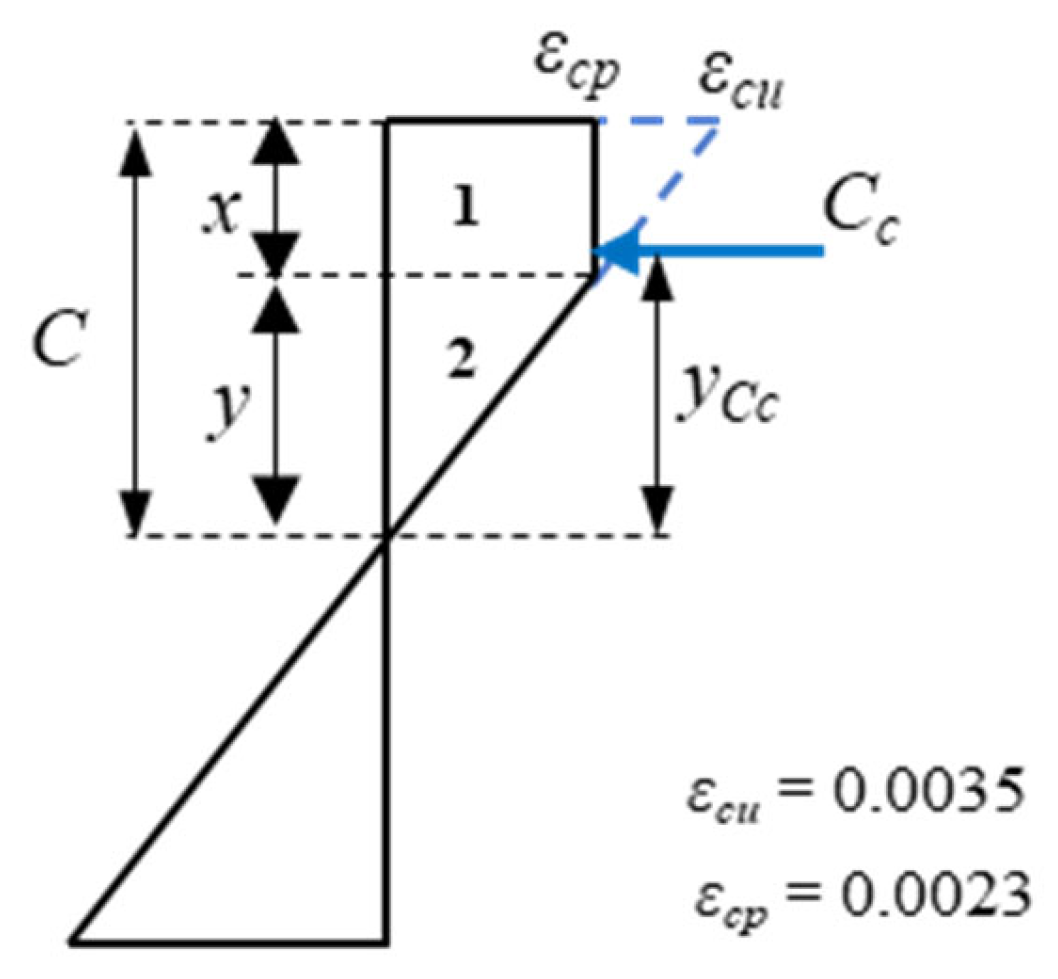
| Elastic compression strain limit: | |
| Ultimate compression strain limit: |
| Layer 2: | |
| Layer 1: |
| Layer 2: | |
| Layer 1: |
| Layer 2: | |
| Layer 1: |
| Equilibrium: |
| Layer 2: |
| Equilibrium: |
| Layer 2: | |
| Layer 1: |
| Layer 2: | |
| Layer 1: |
| Equilibrium: |
| Layer 2: | |
| Layer 1: |
Appendix B. Embedment and Development Length of Dowel Bar
- ȴdb = basic development length (in.);
- λrl = reinforcement location factor (use 1.0);
- λcf = coating factor (use 1.0);
- λrc = reinforcement confinement factor;
- λcr = excess reinforcement factor;
- λ = concrete density modification factor, should be taken as 1.0;
- Cb = the smaller of the distance from the center to the bar or wire being developed to the nearest concrete surface and one-half the center-to-center spacing of the bars or wires being developed (in.);
- Ktr = transverse reinforcement index;
- fy = specified minimum yield strength of reinforcement;
- f’c = compressive strength of concrete of the design (taken as 15 ksi as limited as [30]).
- (a)
- Class A Splice
- (b)
- Class B Splice
- ξ = The transfer length factor, taken as 1.0;
- db = Strand diameter;
- fps = Average stress in prestressing steel at the time for which the nominal resistance of the member is required (ksi);
- fpe = effective stress in prestressing steel after losses (ksi).
Appendix C. Calculation for Near-Surface-Mounted Bar Pile Splice Section Analysis (18 in. UHPC Pile)
| Elastic compression strain limit: | |
| Ultimate compression strain limit: |
| Layer 2: | |
| Layer 1: |
| Layer 2: | |
| Layer 1: |
| Layer 2: | |
| Layer 1: |
| Equilibrium: |
| Layer 2: | |
| Layer 1: |
| Layer 2: | |
| Layer 1: |
| Equilibrium: |
| Top lever arm: |
| Layer 2: | |
| Layer 1: |
| Development length for circular bars: |
| Dimension of grooves: | |
| Clear groove spacing: |
References
- Ultra-High-Performance Concrete: An Emerging Technology Report (ACI 239R-18); American Concrete Institute: Farmington Hills, MI, USA, 2018; ISBN 978-1-64195-034-3.
- Abbas, S.; Nehdi, M.L.; Saleem, M.A. Ultra-High Performance Concrete: Mechanical Performance, Durability, Sustainability and Implementation Challenges. Int. J. Concr. Struct. Mater. 2016, 10, 271–295. [Google Scholar] [CrossRef]
- Graybeal, B. Design and Construction of UHPC Connections. 2019. Available online: https://www.researchgate.net/publication/332079899_Design_and_Construction_of_Field-Cast_UHPC_Connections_2019 (accessed on 12 May 2024).
- Tadros, M.; Lawler, J. Implementation of Ultra-High Performance Concrete in Long-Span Precast Pretensioned Elements for Concrete Buildings and Bridges; Precast/Prestressed Concrete Institute: Tampa, FL, USA, 2021. [Google Scholar]
- Sritharan, S.; Sriram, A.; Dean, B.; Abu-Hawash, A. Use of Ultra-High Performance Concrete in Bridge Design. 2012. Available online: https://www.pwri.go.jp/eng/ujnr/tc/g/pdf/28/28-10-2_Sritharan.pdf (accessed on 13 May 2024).
- Ng, K.W.; Garder, J.; Sritharan, S. Field Investigation of Ultra-High Performance Concrete Piles. Int. Interact. Symp. Ultra-High Perform. Concr. 2016, 1. [Google Scholar] [CrossRef]
- Voort, T.V.; Suleiman, M.; Sritharan, S. Design and Performance Verification of Ultra High Performance Concrete Piles for Deep Foundations; Iowa Department of Transportation: Ames, IA, USA, 2008; p. 224.
- Degen, B.E. Shear Design and Behavior of Ultra-High Performance Concrete; Iowa State University: Ames, IA, USA, 2006. [Google Scholar]
- Garder, J.; Aaleti, S.; Zhong, L.; Sritharan, S. Connection Details and Field Implementation of UHPC Piles—Phase II; Iowa Department of Transportation: Ames, IA, USA, 2019; p. 309.
- Grand, B.A. Types of Piles: Their Characteristics and General Use. 1970. Available online: http://onlinepubs.trb.org/Onlinepubs/hrr/1970/333/333-002.pdf (accessed on 5 October 2023).
- Lau, K.; Permeh, S.; Faridmarandi, S.; Azizinamini, A. Review of Mitigation of Carbonation-Induced Corrosion with UHPC; AMPP Annual Conference + Expo: Denver, CO, USA, 2023. [Google Scholar]
- Yan, P.-Y. Development and Present Situation of Ultra-high Performance Concrete (UHPC) Concrete. 2010. Available online: https://doi.org/10.3969/j.issn.1674-7011.2010.09.009 (accessed on 23 October 2023).
- Wang, B. Corrosion Behavior of Corrosion-Resistant Steel Reinforcements in High and Ultra-High Performance Concrete in Chloride Attack Environments; University of Houston: Houston, TX, USA, 2019. [Google Scholar]
- Roux, N.; Andrade, C.; Sanjuan, M.A. Experimental Study of Durability of Reactive Powder Concretes. J. Mater. Civ. Eng. 1996, 8, 1–6. [Google Scholar] [CrossRef]
- Mostafa, S.A.; EL-Deeb, M.M.; Farghali, A.A.; Faried, A.S. Evaluation of the nano silica and nano waste materials on the corrosion protection of high strength steel embedded in ultra-high performance concrete. Sci. Rep. 2021, 11, 2617. [Google Scholar] [CrossRef] [PubMed]
- Gutierrez Melgarejo, R.C. Mitigation of aging of glass fiber reinforced cement (GRC) using pozzolan and acrylic resin additions. In Proceedings of the 2019 Congreso Internacional de Innovación y Tendencias en Ingenieria (CONIITI), Bogota, Colombia, 2–4 October 2019; IEEE: Bogota, Colombia, 2019; pp. 1–6. [Google Scholar]
- Zhang, J. Application of ultra-high-performance concrete in the marine environment. E3S Web Conf. 2025, 606, 04008. [Google Scholar] [CrossRef]
- Sritharan, S.; Brant, J.B.; Vic, H.P. Characterizing an Ultra-High Performance Material for Bridge Applications under Extreme Loads. In Proceedings of the 3rd International Symposium on High Performance Concrete, Orlando, FL, USA, 19–22 October 2003. [Google Scholar]
- Voort, T.L.V.; Sritharan, S.; Suleiman, M. A Precast UHPC Pile for Substructural Applications. 2007. Available online: https://www.pci.org/PCI_Docs/Papers/2007/A-Precast-Uhpc-Pile-for-Substructural-Applications.pdf (accessed on 21 December 2023).
- Florida Department of Transportation FDOT Developmental Standard Plans. 2023. Available online: https://www.fdot.gov/design/standardplans/dev.shtm (accessed on 11 December 2023).
- Cook, R.A.; McVay, M.C.; Britt, K.C. Alternatives for Precast Pile Splices—Part 1 (FDOT Report); Florida Department of Transportation: Transportation, FL, USA, 2003; p. 45.
- Mullins, G.; Johnson, K.; Sen, R. Post-Tensioned Splice System for Precast, Prestressed Concrete Piles: Part 1, Conceptual design. PCI J. 2018, 63, 26–39. [Google Scholar] [CrossRef]
- PCI Prestressed Concrete Piling Committee. Recommended Practice for Design, Manufacture, and Installation of Prestressed Concrete Piling. PCI J. 2019, 64. [Google Scholar] [CrossRef]
- Bruce, R.N.; Hebert, D.C. Splicing of Precast Prestressed Concrete Piles: Part I—Review and Performance of Splices. PCI J. 1974, 19, 70–97. [Google Scholar] [CrossRef]
- Khedmatgozar Dolati, S.S.; Mehrabi, A. Alternative Systems and Materials for Splicing Prestressed-Precast Concrete Piles. Transp. Res. Rec. 2021, 03611981211052949. [Google Scholar] [CrossRef]
- Aaleti, S.R.; Jessica, G.; Sritharan, S. Experimental Evaluation of UHPC Piles with a Splice and Pile-to-Abutment Connection Performance. 2012. Available online: https://www.pci.org/PCI_Docs/Papers/2012/Experimental-Evaluation-of-Uhpc-Piles-with-a-Splice-and-Pile-To-Abutment-Connection-Performance.pdf (accessed on 10 December 2022).
- Zeng, J.-J.; Feng, P.; Dai, J.-G.; Zhuge, Y. Development and behavior of novel FRP-UHPC tubular members. Eng. Struct. 2022, 266, 114540. [Google Scholar] [CrossRef]
- Zeng, J.-J.; Chen, S.-P.; Feng, P.; Zhuge, Y.; Peng, K.-D.; Dai, J.-G.; Fan, T.-H. FRP bar-reinforced ultra-high-performance concrete plates with a grouting sleeve connection: Development and flexural behavior. Eng. Struct. 2023, 287, 116164. [Google Scholar] [CrossRef]
- Sritharan, S.; Aaleti, S. Experimental and Analytical Investigation of UHPC Pile-to-Abutment Connections. In Proceedings of the First International Interactive Symposium on UHPC, Des Moines, IA, USA, 18–20 July 2016; Iowa State University Digital Press: Ames, IA, USA, 2016. [Google Scholar]
- Ng, K.W.; Garder, J.; Sritharan, S. Investigation of ultra high performance concrete piles for integral abutment bridges. Eng. Struct. 2015, 105, 220–230. [Google Scholar] [CrossRef]
- Odelola, M.; Dolati, S.S.K.; Mehrabi, A.; Garber, D. Ultra-High-Performance Concrete (UHPC) Piles and Splicing Options. Appl. Sci. 2024, 14, 827. [Google Scholar] [CrossRef]
- Mullins, G.; Sen, R. Investigation and Development of an Effective, Economical and Efficient Concrete Pile Splice (Final Report); Florida Department of Transportation: Tallahassee, FL, USA, 2015.
- Mehrabi, A.; Farhangdoust, S.; Dolati, S.S.K.; Tabiatnejad, D.; Lee, S.J.; Garber, D. Epoxy-Dowel Pile Splice Evaluation (FDOT Report); Florida Department of Transportation: Tallahassee, FL, USA, 2022; p. 307.
- Christopher, H.; Deanna, A.; Laura, B. Methods for Strengthening Reinforced Concrete Bridge Girder Containing Poorly Detailed Flexural Steel Using Near-Surface Mounted Metallics; Oregon State University. School of Civil and Construction Engineering: Corvallis, OR, USA, 2015. [Google Scholar]
- Dolati, S.S.K.; Mehrabi, A. NSM FRP Pile-Splice System for Prestressed Precast Concrete Piles. Pract. Period. Struct. Des. Constr. 2022, 27. [Google Scholar] [CrossRef]
- Dolati, S.S.K.; Mehrabi, A. NSMB Pile Splice System for Precast Concrete Piles. US11319689B1, 3 May 2022. [Google Scholar]
- Seyed Saman Khedmatgozar, D.; Mehrabi, A. Two New Methods for Establishing Simple Yet Durable Connection System for Precast Elements; ASCE: Reston, VA, USA, 2023; pp. 293–303. [Google Scholar]
- Florida Department of Transportation (FDOT). Standard Specification for Road and Bridge Construction; Florida Department of Transportation (FDOT): Tallahassee, FL, USA, 2022; p. 1275.
- American Association of State Highway and Transportation Officials (AASHTO). AASHTO LRFD Bridge Design Specification, Customary U.S. Units, 9th ed.; American Association of State Highway and Transportation Officials (AASHTO): Washington, DC, USA, 2020. [Google Scholar]
- American Association of State Highway and Transportation Officials. AASHTO Guide Specifications for Structural Design with Ultra-High-Performance Concrete; American Association of State Highway and Transportation Officials (AASHTO): Washington, DC, USA, 2023. [Google Scholar]
- American Concrete Institute. ACI 440.2R-17: Guide for the Design and Construction of Externally Bonded FRP Systems for Strengthening Concrete Structures; American Concrete Institute: Farmington Hills, MI, USA, 2017. [Google Scholar]


| Shape Type | Advantages | Disadvantages |
|---|---|---|
1. Square with rectangular void | Symmetrical section Reduces cross-section while keeping the square shape. | Issues with void (unequal wall thickness if void moves). |
2. Square with circular void | Potential for more splicing options (largest cross-section). Symmetrical section. | Weight is heavier than the rectangular void option. Issues with void (unequal wall thickness if void moves) |
3. Octagonal with void 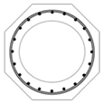 | Optimization of the shape to strength capacity. Reduced weight. | New forms might be required. Issue with forming of the void during construction. Splicing might be difficult. |
4. H-pile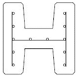 | Largest surface area. Surface area contributes to the side friction. Reduced weight compared to square shape. Most cast and driven pile shape in construction. Easily adopted in pile foundation. | Non-symmetrical section. Direction of pile is important during placement. New forms may be required. Inconsistent dimensions of flanges. Pile splicing could be more challenging. |
| Pile Size | Bending Strength |
|---|---|
| 18 in. | 245 k-ft |
| 24 in. | 600 k-ft |
| 30 in. | 950 k-ft |
| Property | Value | Strand and Prestressing | Value |
|---|---|---|---|
| Section area (in2) | 324 | No. of strand, strands | 10 |
| Section moment of inertia (in4) | 8748 | Strand stress, ksi | 42.9 |
| Section modulus (in3) | 972 | Total area of strand, Aps (in2) | 2.170 |
| Weight (kip/ft) | 0.349 | Ultimate strength fpu (ksi) | 270 |
| Property | Variable | Value Used |
|---|---|---|
| Unit weight of concrete | γc | 155 pcf |
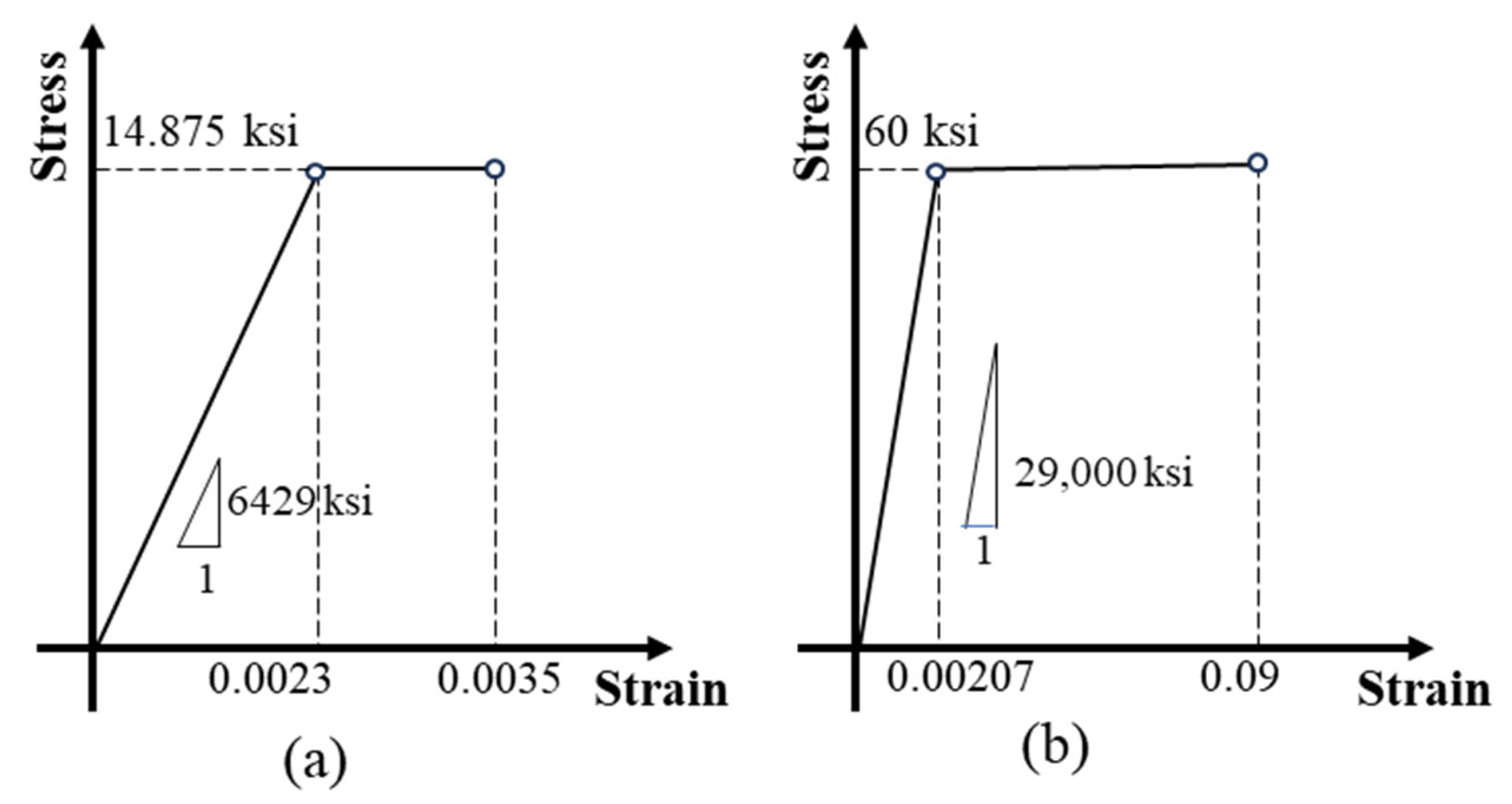
| Compression strength | f′c | 17.5 ksi |
| Compression reduction factor | αu | 0.85 |
| Ultimate compressive strain | εcu | 0.0035 |
| Effective cracking stress | ft,cr | 0.75 ksi |
| Localization stress | ft,loc | 0.75 ksi |
| Localization strain | εt,loc | 0.0025 |
| Tension reduction factor | γu | 1.0 |
| Pile Orientation | Pile Capacity | 80% for Pile Splices |
|---|---|---|
| Strong Axis | 270 k-ft | 216 k-ft |
| Weak Axis | 228 k-ft | 182 k-ft |
| Property | Value | |
|---|---|---|
| Bar size | #10 | |
| Yield strength | fy | 60 ksi |
| Modulus of elasticity | Es | 29,000 ksi |
| Yield strain | 0.00207 | |
| Area of one bar | A | 0.196 in2 |
| Property | Value | |
|---|---|---|
| Compression strength | f′c | 17.5 ksi |
| Compression reduction factor | αu | 0.85 |
| Ultimate compressive strain | εcu | 0.0035 |
| * Elastic compression strain limit | 0.0023 | |
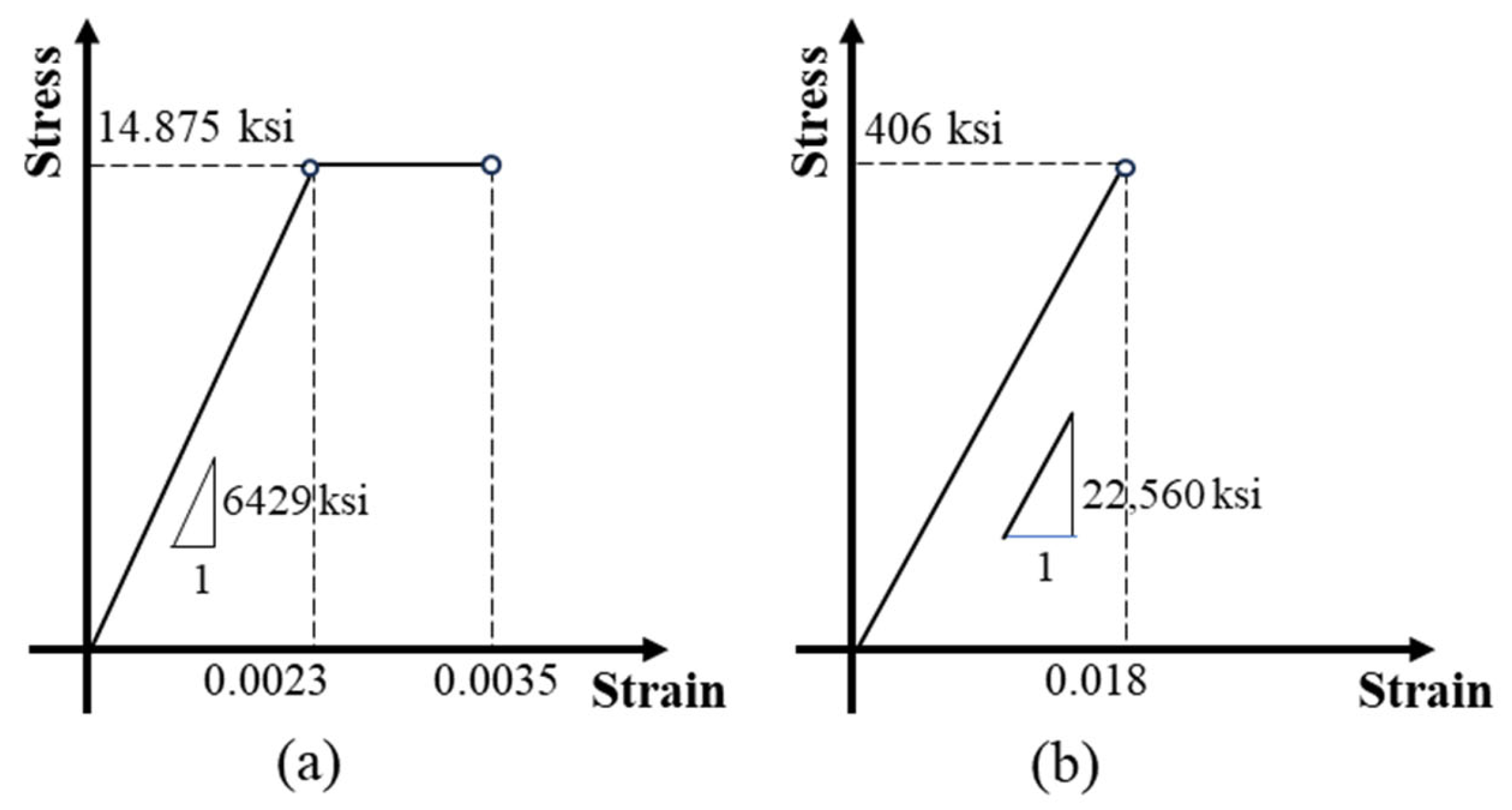
| * Modulus of elasticity | Ec | 6429 ksi |
| Length Type | Value |
|---|---|
| Strand development length, ℓd | 30 in. |
| Dowel length at upper pile segment, L′D | 30 in. |
| Dowel length at lower pile segment, LD | 30 in. |
| Dowel hole length at lower pile segment, LH | 32 in. |
| Property | Value | |
|---|---|---|
| Bar size | #4 | |
| Tensile strength | 406 ksi | |
| Tensile modulus of elasticity | 22,560 ksi | |
| Area of one bar | A | 0.196 in2 |
| Orientation | Dowel (Quantity-Bar Size) | Factored Moment Strength (kip-ft) | Embedment Length | Diagram Illustration | ||
|---|---|---|---|---|---|---|
| L’D (in.) | LD (in.) | LH (in.) | ||||
| Strong Axis | 8-#10 | 343 | 30 | 30 | 32 | 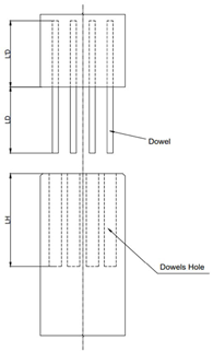 |
| Weak Axis | 8-#10 | 316 | 30 | 30 | 32 | |
| Orientation | CFRP Bars (Quantity-Bar Size) | Factored Nominal Moment (kip-ft) | Groove Dimensions (in.) | Groove Spacing (in.) | Development Length (in.) |
|---|---|---|---|---|---|
| Strong Axis | 12-#4 | 328 | 0.75 | 1.5 | 35 |
| Weak Axis | 12-#4 | 241 | 0.75 | 1.5 | 35 |
| Pile Splice Method | Splice Moment Capacity (k-ft) | 80% Calculated Pile Capacity (Pure Bending) (k-ft) | FDOT Standard Requirement (k-ft) | Meet the Minimum Requirement | |||
|---|---|---|---|---|---|---|---|
| Strong Axis | Weak Axis | Strong Axis | Weak Axis | Strong Axis | Weak Axis | ||
| Epoxy-bonded dowel | 343 | 316 | 216 | 182 | 245 | Yes | Yes |
| NSM FRP | 328 | 241 | 216 | 182 | 245 | Yes | No * |
Disclaimer/Publisher’s Note: The statements, opinions and data contained in all publications are solely those of the individual author(s) and contributor(s) and not of MDPI and/or the editor(s). MDPI and/or the editor(s) disclaim responsibility for any injury to people or property resulting from any ideas, methods, instructions or products referred to in the content. |
© 2025 by the authors. Licensee MDPI, Basel, Switzerland. This article is an open access article distributed under the terms and conditions of the Creative Commons Attribution (CC BY) license (https://creativecommons.org/licenses/by/4.0/).
Share and Cite
Odelola, M.; Khedmatgozar Dolati, S.S.; Mehrabi, A.; Garber, D. Alternative Splicing Options for Ultra-High-Performance Concrete (UHPC) H-Piles. Buildings 2025, 15, 481. https://doi.org/10.3390/buildings15030481
Odelola M, Khedmatgozar Dolati SS, Mehrabi A, Garber D. Alternative Splicing Options for Ultra-High-Performance Concrete (UHPC) H-Piles. Buildings. 2025; 15(3):481. https://doi.org/10.3390/buildings15030481
Chicago/Turabian StyleOdelola, Michael, Seyed Saman Khedmatgozar Dolati, Armin Mehrabi, and David Garber. 2025. "Alternative Splicing Options for Ultra-High-Performance Concrete (UHPC) H-Piles" Buildings 15, no. 3: 481. https://doi.org/10.3390/buildings15030481
APA StyleOdelola, M., Khedmatgozar Dolati, S. S., Mehrabi, A., & Garber, D. (2025). Alternative Splicing Options for Ultra-High-Performance Concrete (UHPC) H-Piles. Buildings, 15(3), 481. https://doi.org/10.3390/buildings15030481