
A Theoretical and Numerical Approach to Ensure Ductile Failure in Strengthened Reinforced Concrete Slabs with Fiber-Reinforced Polymer Sheets


Abstract
:1. Introduction
2. Theoretical Overview
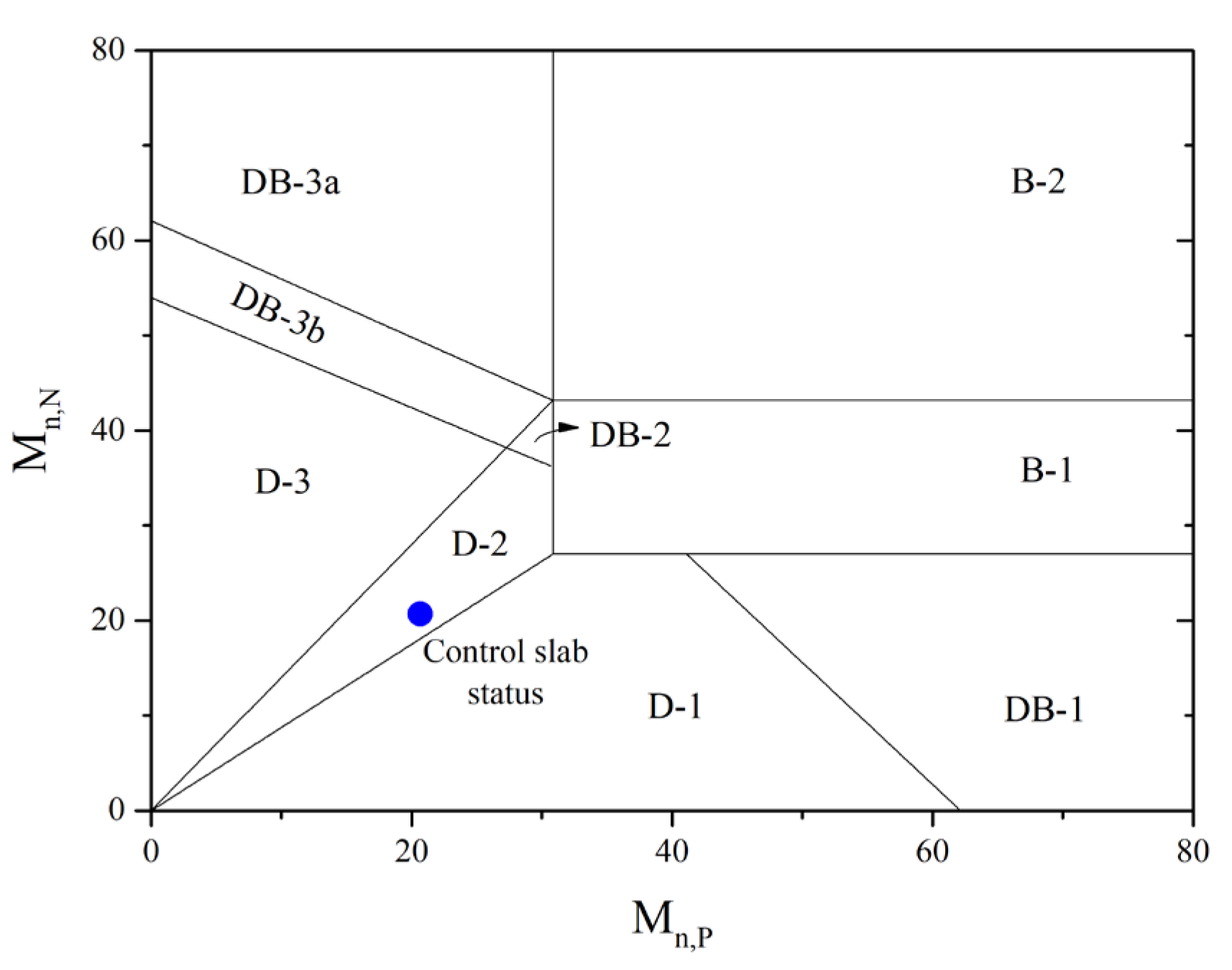
2.1. Overview of Failure Limits
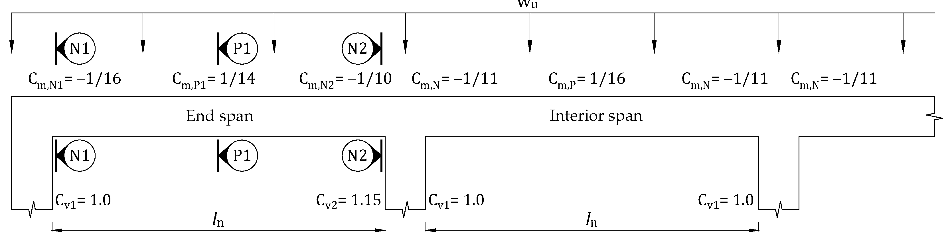
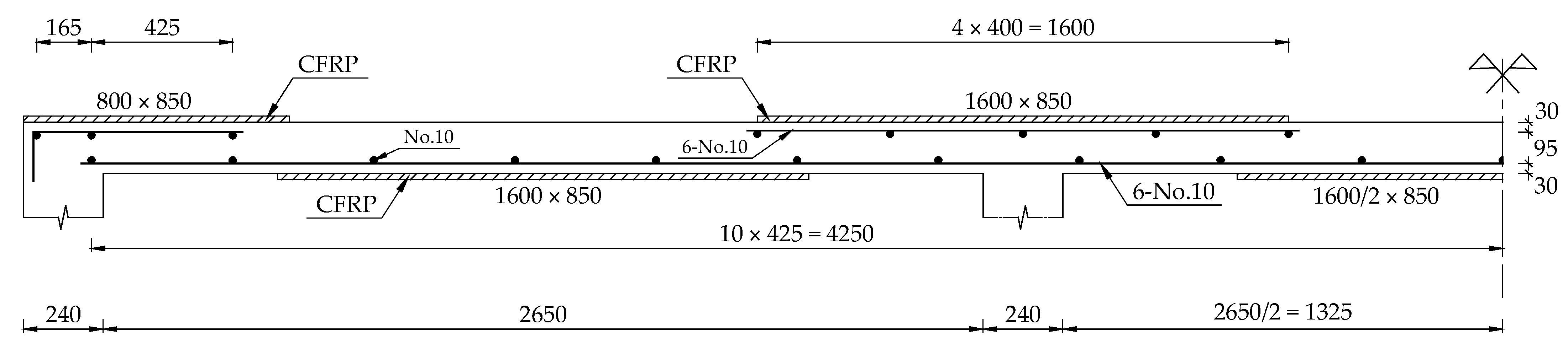
2.2. Design Example
3. Numerical Simulation
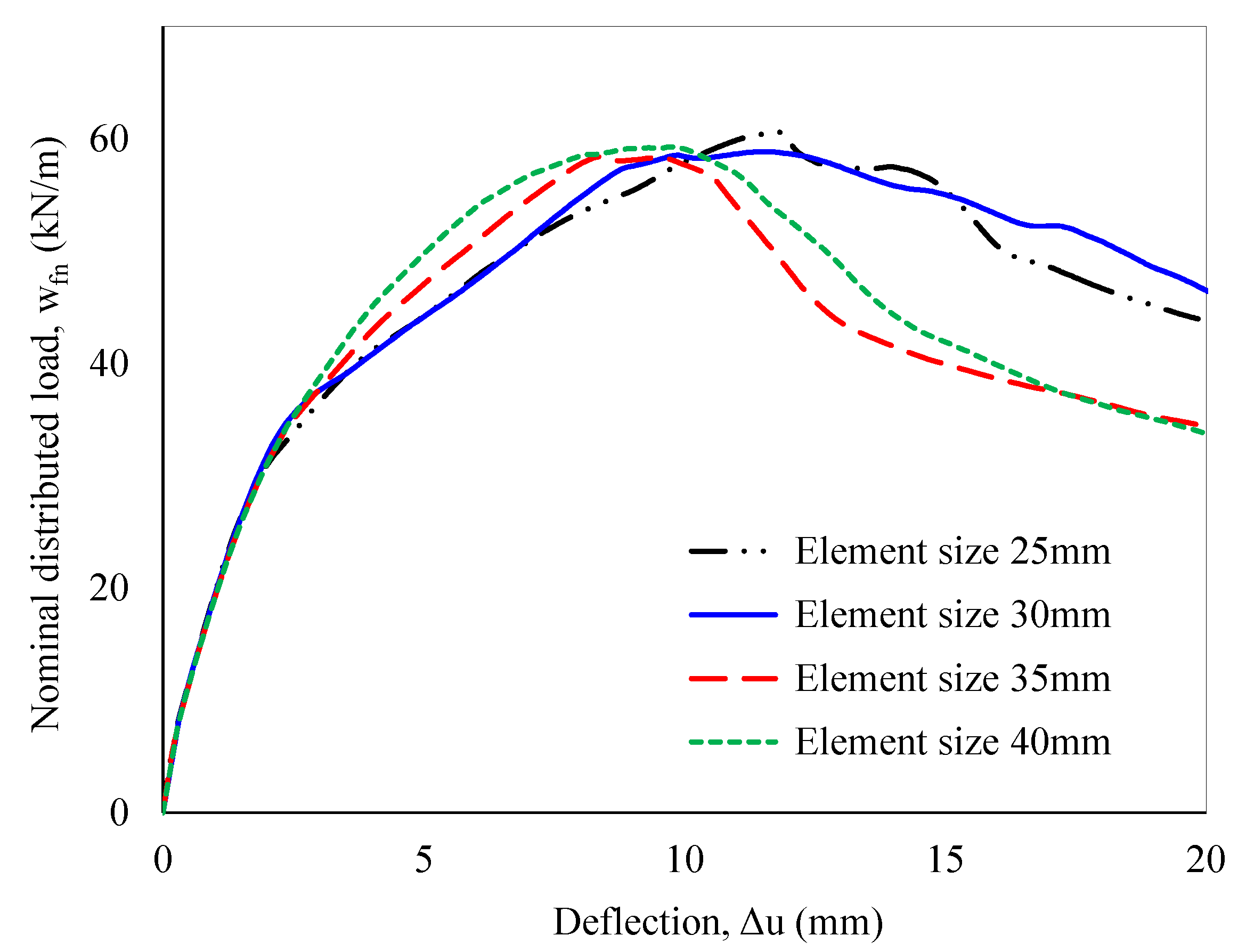
3.1. Boundary Conditions, Element Type, and Mesh
3.2. Material Model
4. Results and Discussion
4.1. Theoretical Analysis
4.2. Numerical Analysis
5. Conclusions
Author Contributions
Funding
Data Availability Statement
Conflicts of Interest
Nomenclature
| b | Width of a control slab |
| Cm, Cv | Moment and shear coefficients |
| Cv | Shear coefficient |
| d | Distance between the extreme compression fiber and the center of the steel |
| df | Distance between the extreme compression fiber and the center of FRP laminates |
| Ec, Es, Ef | Modulus of elasticity of concrete, steel, and FRP |
| f′c | Compressive strength of concrete |
| ffe | FRP effective stress |
| ffu | Designed ultimate strength of FRP |
| f*fu | FRP ultimate tensile strength |
| fs | Tensile steel stress |
| fy | Yield stress of tension steel |
| Icr | Cracked moment |
| ln | Length of clear span |
| Mn, Vn | Nominal moment and shear strength |
| Mn,P, Mn,N | Mid-span and support sections’ moment-carrying capacities |
| Mns, Mnf | Moments contributed by tensile steel and FRP |
| MN1 | Moments carrying capacities of the N1 section |
| MD | Dead-load moment |
| n | Number of FRP layers |
| tF | FRP thickness |
| wfn | Nominal failure load |
| wu | Design factored load |
| ψf | FRP strength reduction factor |
| εbi | Existing state strain of FRP |
| εcu, εfu | Ultimate strains of concrete and FRP |
| εfd | Debonding strain of FRP |
| εfe, εs | Strains of FRP and tensile steel |
References
- Zamani Beydokhti, E.; Shariatmadar, H. Strengthening and rehabilitation of exterior RC beam–column joints using carbon-FRP jacketing. Mater. Struct. 2016, 49, 5067–5083. [Google Scholar] [CrossRef]
- Martínez, S.; de Diego, A.; Castro, V.J.; Echevarría, L.; Barroso, F.J.; Rentero, G.; Soldado, R.P.; Gutiérrez, J.P. Strengthening of Low-Strength Concrete Columns with Fibre Reinforced Polymers. Full-Scale Tests. Infrastructures 2020, 5, 91. [Google Scholar] [CrossRef]
- Hariri-Ardebili, M.A.; Sanchez, L.; Rezakhani, R. Aging of Concrete Structures and Infrastructures: Causes, Consequences, and Cures. Adv. Mater. Sci. Eng. 2020, 2020, 9370591. [Google Scholar] [CrossRef]
- Ma, Y.; Zhang, J.; Wang, L.; Liu, Y. Probabilistic prediction with Bayesian updating for strength degradation of RC bridge beams. Struct. Saf. 2013, 44, 102–109. [Google Scholar] [CrossRef]
- Fathelbab, F.A.; Ramadan, M.S.; Al-Tantawy, A. Strengthening of RC bridge slabs using CFRP sheets. Alex. Eng. J. 2014, 53, 843–854. [Google Scholar] [CrossRef]
- Hu, J.Y.; Zhang, S.S.; Chen, E.; Li, W.G. A review on corrosion detection and protection of existing reinforced concrete (RC) structures. Constr. Build. Mater. 2022, 325, 126718. [Google Scholar] [CrossRef]
- Ma, Z.; Shen, J.; Wang, C.; Wu, H. Characterization of sustainable mortar containing high-quality recycled manufactured sand crushed from recycled coarse aggregate. Cem. Concr. Compos. 2022, 132, 104629. [Google Scholar] [CrossRef]
- Nguyen, X.T.; Park, J.S. Flexural Behavior of Steel Beams Strengthened with CFRP Under Fire. Int. J. Steel Struct. 2022, 22, 1769–1785. [Google Scholar] [CrossRef]
- Maxineasa, S.G.; Taranu, N. 24—Life cycle analysis of strengthening concrete beams with FRP. In Eco-Efficient Repair and Rehabilitation of Concrete Infrastructures; Pacheco-Torgal, F., Melchers, R.E., Shi, X., Belie, N.D., Tittelboom, K.V., Sáez, A., Eds.; Woodhead Publishing: Sawston, UK, 2018; pp. 673–721. [Google Scholar]
- Zhu, Y.; Zhang, Y.; Hussein, H.H.; Chen, G. Flexural strengthening of reinforced concrete beams or slabs using ultra-high performance concrete (UHPC): A state of the art review. Eng. Struct. 2020, 205, 110035. [Google Scholar] [CrossRef]
- Nguyen, T.N.M.; Han, T.H.; Park, J.K.; Kim, J.J. Strength and Toughness of Waste Fishing Net Fiber-Reinforced Concrete. Materials 2021, 14, 7381. [Google Scholar] [CrossRef]
- Nguyen, T.N.M.; Moon, J.; Kim, J.J. Microstructure and mechanical properties of hardened cement paste including Nylon 66 nanofibers. Constr. Build. Mater. 2020, 232, 117134. [Google Scholar] [CrossRef]
- Huang, Y.; Grünewald, S.; Schlangen, E.; Luković, M. Strengthening of concrete structures with ultra high performance fiber reinforced concrete (UHPFRC): A critical review. Constr. Build. Mater. 2022, 336, 127398. [Google Scholar] [CrossRef]
- Thermou, G.E.; Pantazopoulou, S.J.; Elnashai, A.S. Flexural Behavior of Brittle RC Members Rehabilitated with Concrete Jacketing. J. Struct. Eng. 2007, 133, 1373–1384. [Google Scholar] [CrossRef]
- Holman Jerry, W.; Cook John, P. Steel Plates for Torsion Repair of Concrete Beams. J. Struct. Eng. 1984, 110, 10–18. [Google Scholar] [CrossRef]
- Zeng, J.-J.; Duan, Z.-J.; Guo, Y.-C.; Xie, Z.-H.; Li, L.-J. Novel fiber-reinforced polymer cross wrapping strengthening technique: A comparative study. Adv. Struct. Eng. 2019, 23, 979–996. [Google Scholar] [CrossRef]
- Lin, S.; Zhao, Y.-G.; Li, J. An improved wrapping scheme of axially loaded fiber-reinforced polymer confined concrete columns. Compos. Struct. 2019, 226, 111242. [Google Scholar] [CrossRef]
- Al-Ameedee, H.S.; Al-Khafaji, H.M. Improving the flexural behavior of RC beams strengthening by near-surface mounting. Mech. Behav. Mater. 2022, 31, 701–709. [Google Scholar] [CrossRef]
- Jedrzejko, M.J.; Tian, J.; Zhang, S.S.; Ke, Y.; Nie, X.F.; Yang, Y.M. Strengthening of RC beams in shear with novel near-surface mounted (NSM) U-shaped fiber-reinforced polymer (FRP) composites. Eng. Struct. 2023, 292, 116479. [Google Scholar] [CrossRef]
- Al-Zu’bi, M.; Fan, M.; Bertolesi, E.; Anguilano, L. A review on retrofitting concrete members with near-surface mounted-fiber reinforced polymer composites. Struct. Concr. 2024, 25, 2242–2268. [Google Scholar] [CrossRef]
- Zeng, J.-J.; Zeng, W.-B.; Ye, Y.-Y.; Liao, J.; Zhuge, Y.; Fan, T.-H. Flexural behavior of FRP grid reinforced ultra-high-performance concrete composite plates with different types of fibers. Eng. Struct. 2022, 272, 115020. [Google Scholar] [CrossRef]
- Haji, M.; Naderpour, H.; Kheyroddin, A. Experimental study on influence of proposed FRP-strengthening techniques on RC circular short columns considering different types of damage index. Compos. Struct. 2019, 209, 112–128. [Google Scholar] [CrossRef]
- Barris, C.; Sala, P.; Gómez, J.; Torres, L. Flexural behaviour of FRP reinforced concrete beams strengthened with NSM CFRP strips. Compos. Struct. 2020, 241, 112059. [Google Scholar] [CrossRef]
- Basaran, B.; Kalkan, I. Development length and bond strength equations for FRP bars embedded in concrete. Compos. Struct. 2020, 251, 112662. [Google Scholar] [CrossRef]
- Mukhtar, F.M.; Arowojolu, O. Recent developments in experimental and computational studies of hygrothermal effects on the bond between FRP and concrete. J. Reinf. Plast. Compos. 2020, 39, 422–442. [Google Scholar] [CrossRef]
- Wang, X.; Yang, Y.; Yang, R.; Liu, P. Experimental Analysis of Bearing Capacity of Basalt Fiber Reinforced Concrete Short Columns under Axial Compression. Coatings 2022, 12, 654. [Google Scholar] [CrossRef]
- Vu, H.D.; Phan, D.N. A framework for predicting the debonding failure modes of RC beams strengthened flexurally with FRP sheets. Innov. Infrastruct. Solut. 2022, 7, 292. [Google Scholar] [CrossRef]
- Hegde, S.; Satish Shenoy, B.; Chethan, K.N. Review on carbon fiber reinforced polymer (CFRP) and their mechanical performance. Mater. Today Proc. 2019, 19, 658–662. [Google Scholar] [CrossRef]
- Xian, G.; Guo, R.; Li, C.; Wang, Y. Mechanical performance evolution and life prediction of prestressed CFRP plate exposed to hygrothermal and freeze-thaw environments. Compos. Struct. 2022, 293, 115719. [Google Scholar] [CrossRef]
- Rabinovitch, O.; Frostig, Y. Experiments and analytical comparison of RC beams strengthened with CFRP composites. Compos. Part B Eng. 2003, 34, 663–677. [Google Scholar] [CrossRef]
- Breveglieri, M.; Barros, J.; Dalfre, G.; Aprile, A. Assessment of the effectiveness of a NSM-CFRP flexural strengthening technique for continuous RC slabs. In Proceedings of the Fib Symposium PRAGUE 2011, Session 5: Combination of Structural Concrete with Other Materials, Prague, Czech Republic, 8–10 June 2011; pp. 1–10. [Google Scholar]
- Obaidat Yasmeen, T.; Heyden, S.; Dahlblom, O. Evaluation of Parameters of Bond Action between FRP and Concrete. J. Compos. Constr. 2013, 17, 626–635. [Google Scholar] [CrossRef]
- Hawileh, R.A.; Rasheed, H.A.; Abdalla, J.A.; Al-Tamimi, A.K. Behavior of reinforced concrete beams strengthened with externally bonded hybrid fiber reinforced polymer systems. Mater. Des. 2014, 53, 972–982. [Google Scholar] [CrossRef]
- Bocciarelli, M.; Pisani, M.A. Modified force method for the nonlinear analysis of FRP reinforced concrete beams. Compos. Struct. 2015, 131, 645–653. [Google Scholar] [CrossRef]
- Haciyev, V.C.; Sofiyev, A.H.; Kuruoglu, N. Free bending vibration analysis of thin bidirectionally exponentially graded orthotropic rectangular plates resting on two-parameter elastic foundations. Compos. Struct. 2018, 184, 372–377. [Google Scholar] [CrossRef]
- Al-Rousan, R.; Issa, M.; Shabila, H. Performance of reinforced concrete slabs strengthened with different types and configurations of CFRP. Compos. Part B Eng. 2012, 43, 510–521. [Google Scholar] [CrossRef]
- Phan Duy, N.; Dang, V. Limiting Reinforcement Ratios for Hybrid GFRP/Steel Reinforced Concrete Beams. Int. J. Eng. Technol. Innov. 2021, 11, 01–11. [Google Scholar] [CrossRef]
- Wei, L.; Ueda, T.; Matsumoto, K.; Zhu, J.-H. Experimental and analytical study on the behavior of RC beams with externally bonded carbon-FRCM composites. Compos. Struct. 2021, 273, 114291. [Google Scholar] [CrossRef]
- Nguyen, H.Q.; Nguyen, T.N.M.; Lee, D.H.; Kim, J.J. A Design Method to Induce Ductile Failure of Flexural Strengthened One-Way RC Slabs. Materials 2021, 14, 7647. [Google Scholar] [CrossRef]
- Kim, J.J.; Noh, H.-C.; Taha, M.M.R.; Mosallam, A. Design limits for RC slabs strengthened with hybrid FRP–HPC retrofit system. Compos. Part B 2013, 51, 19–27. [Google Scholar] [CrossRef]
- Nguyen, H.Q.; Yang, K.; Kim, J.J. An Efficient Method for Optimizing HPC-FRP Retrofit Systems of Flexural Strengthened One-Way Continuous Slabs Based on ACI 440.2R. Materials 2022, 15, 8430. [Google Scholar] [CrossRef]
- Ahmad, H.; Elnemr, A.; Ali, N.; Hussain, Q.; Chaiyasarn, K.; Joyklad, P. Finite Element Analysis of Glass Fiber-Reinforced Polymer-(GFRP) Reinforced Continuous Concrete Beams. Polymers 2021, 13, 4468. [Google Scholar] [CrossRef]
- Nguyen, H.Q.; Han, T.H.; Park, J.K.; Kim, J.J. Impact of Bond–Slip Models on Debonding Behavior in Strengthened RC Slabs Using Recycled Waste Fishing Net Sheets. Polymers 2024, 16, 3093. [Google Scholar] [CrossRef] [PubMed]
- ABAQUS/FEA. Internet Manual; Dassault Systèmes Simulia Corp: Johnston, RI, USA, 2024. [Google Scholar]
- ACI 440.2R-17; Guide for the Design and Construction of Externally Bonded FRP Systems for Strengthening Concrete Structures. American Concrete Institute: Farmington Hills, MI, USA, 2017.
- ACI 318M-19; Building Code Requirements for Structural Concrete and Commentary, Metric. American Concrete Institute: Farmington Hills, MI, USA, 2019.
- Hashim, D.T.; Hejazi, F.; Lei, V.Y. Simplified Constitutive and Damage Plasticity Models for UHPFRC with Different Types of Fiber. Int. J. Concr. Struct. Mater. 2020, 14, 45. [Google Scholar] [CrossRef]
- Othman, H.; Marzouk, H. Applicability of damage plasticity constitutive model for ultra-high performance fibre-reinforced concrete under impact loads. Int. J. Impact Eng. 2018, 114, 20–31. [Google Scholar] [CrossRef]
- Le Minh, H.; Khatir, S.; Abdel Wahab, M.; Cuong-Le, T. A concrete damage plasticity model for predicting the effects of compressive high-strength concrete under static and dynamic loads. J. Build. Eng. 2021, 44, 103239. [Google Scholar] [CrossRef]
- Yanhui, L.; Al-Bukhaiti, K.; Shichun, Z.; Abas, H.; Nan, X.; Lang, Y.; Yu, Y.X.; Daguang, H. Numerical study on existing RC circular section members under unequal impact collision. Sci. Rep. 2022, 12, 14793. [Google Scholar] [CrossRef]
- FIB-Federation-Internationale-du-Beton. Fib Model Code for Concrete Structures 2010; John Wiley & Sons: Hoboken, NJ, USA, 2013. [Google Scholar]
- Pressmair, N.; Brosch, F.; Hammerl, M.; Kromoser, B. Non-linear material modelling strategy for conventional and high-performance concrete assisted by testing. Cem. Concr. Res. 2022, 161, 106933. [Google Scholar] [CrossRef]


| Failure Region | 1st Plastic Hinge | 2nd Plastic Hinge | 3rd Plastic Hinge | Shear Failure | Failure Mode |
|---|---|---|---|---|---|
| D-1 | N2 | N1 | P1 | - | Ductile |
| D-2 | N2 | P1 | N1 | - | Ductile |
| D-3 | P1 | N2 | N1 | - | Ductile |
| DB-1 | N2 | N1 | - | N2 | Brittle |
| DB-2 | N2 | P1 | - | N2 | Brittle |
| DB-3a | P1 | - | - | N2 | Brittle |
| DB-3b | P1 | N2 | - | N2 | Brittle |
| B-1 | N2 | - | - | N2 | Brittle |
| B-2 | - | - | - | N2 | Brittle |
| Failure Region | Nominal Failure Load | |
|---|---|---|
| D-1 | (12) | |
| D-2 | (13) | |
| D-3 | (14) | |
| Other regions | (15) |
| Section | RC Slab | CFRP | ||||||||
|---|---|---|---|---|---|---|---|---|---|---|
| f′c (MPa) | As (mm2) | d (mm) | fy (MPa) | Es (GPa) | γc (kg/m3) | f*fu (MPa) | Ef (GPa) | γF (kg/m3) | ||
| Mid-span | 28 | 428 | 125 | 400 | 200 | 2400 | 600 | 40 | 1200 | |
| Supports | ||||||||||
| Analysis | Control Slab |
|---|---|
| Nominal resistances | Mn,N = Mn,P = 20.67 kNm; Vn = 93.7 kN |
| Failure region | D-2 according to Figure 5 |
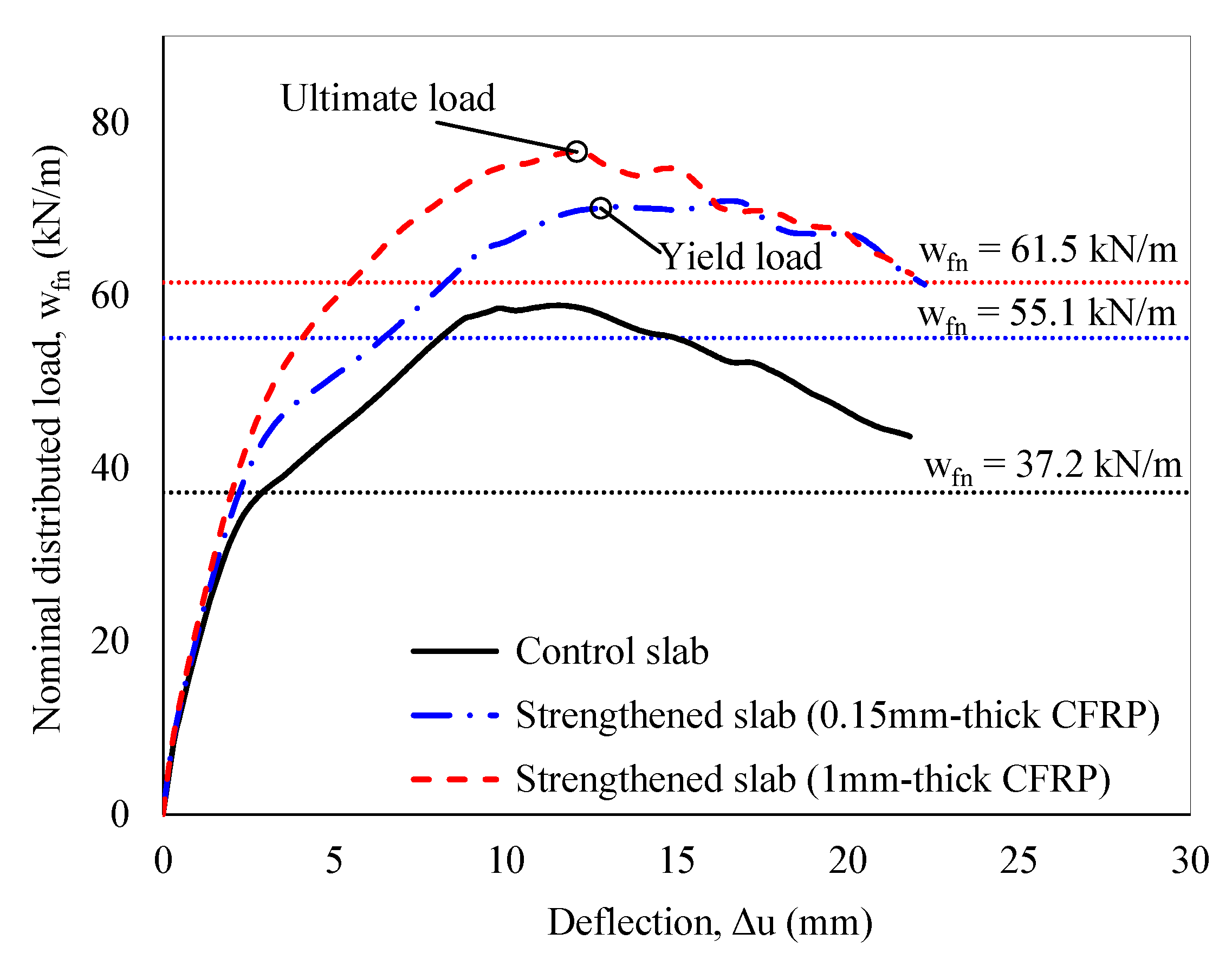
| Nominal failure load | wfn = 37.2 kN/m according to Equation (13) |
| Self-weight | = 24(0.85)(0.155) = 3.16 kN/m |
| Young modulus | = = 24,900 MPa |
| Support, kd | kd = 28 mm |
| Support, cracking moment | Icr,N = |
| The ultimate strength and strain of CFRP (CE = 1) | = 600 MPa; = 0.015 |
| Moment due to dead load | at N2 section: = = 2.22 kNm at mid-span section: = = 1.59 kNm |
| Existing state of strain | at N2 section: = = 0.000295 at mid-span section: = = 0.000211 |
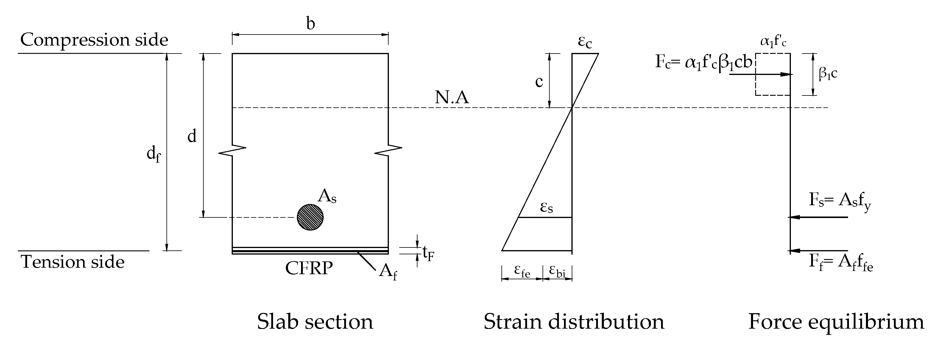
| At Support (N2 Section) | At Mid-Span | |
|---|---|---|
| 1. Assume CFRP thicknesses | tF,N = 1 mm | tF,P = 1 mm |
| 2. Debonding strain of CFRP | = 0.0108 = 0.0135 | |
| 3. Assume neutral axis depth | cN = 30.36 mm | cP = 30.38 mm |
| 4. Calculate CFRP strain (εfe), CFRP stress (ffe), and concrete strain (εc) | = 0.0108(40,000) = 433.9 MPa = = 0.0027 | = 0.0108(40,000) = 433.9 MPa = = 0.00269 |
| 5. Calculate strain (εs) and stress (fs) in the reinforcing steel | = = 0.00843 = = 1686 MPa | = = 0.00836 = = 1672 MPa |
| 6. Check for force equilibrium ; is the strain relative to Check the neutral axis depth | ||
| 7. Calculate nominal flexural strength () Steel contribution: CFRP contribution: | ||
| 8. Calculate nominal shear strength | ||
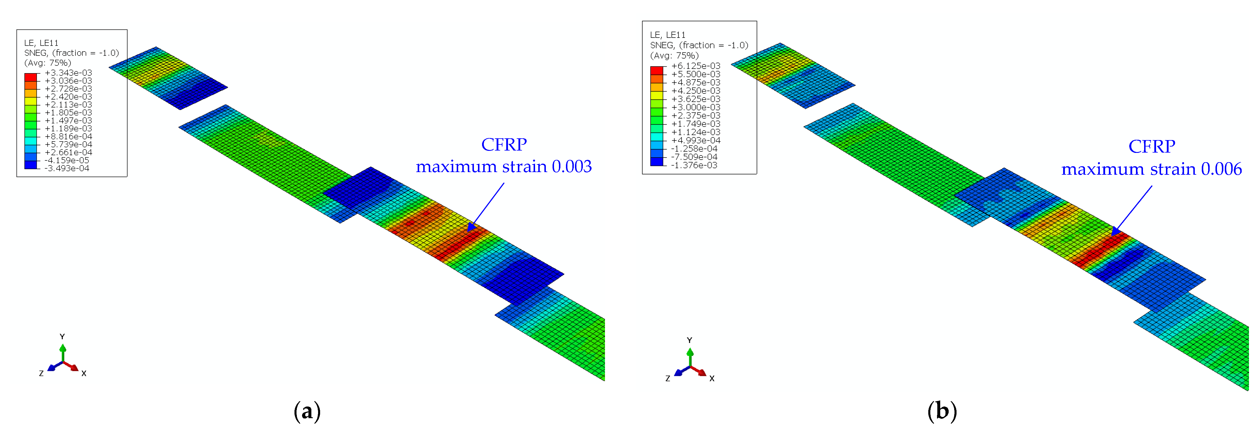
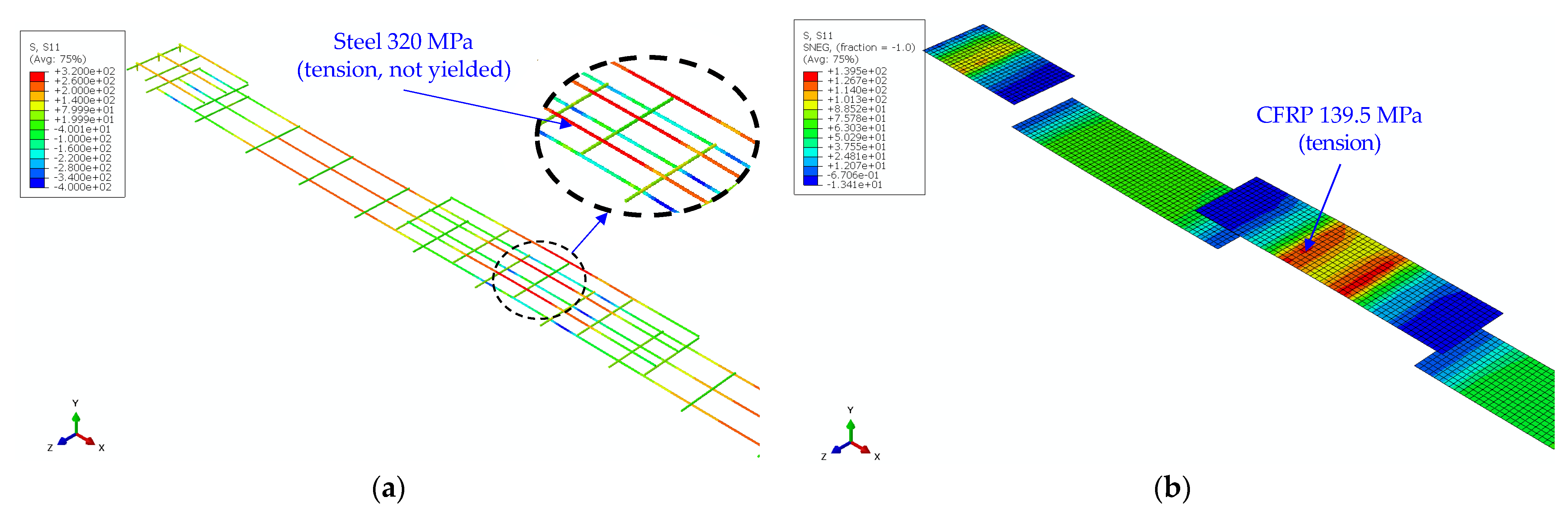
| 9. Determine failure region and nominal failure load | B-2, as shown in Figure 9a; Equation (15), | |
| Iteratively adjust the CFRP thickness to ensure ductile failure | This can be achieved with tF = 0.15 mm; Failure region D-2, as shown in Figure 9b; Failure load wfn = 55.1 kN/m |
| Slab | Failure Region | wfn (kN/m) | tF (mm) | Failure Mode | |
|---|---|---|---|---|---|
| Control slab | D-2 | 37.2 | [100%] | - | Ductile |
| Strengthened slab | D-2 | 55.1 | [148%] | 0.15 | Ductile |
| B-2 | 61.5 | [165%] | 1.00 | Brittle | |
Disclaimer/Publisher’s Note: The statements, opinions and data contained in all publications are solely those of the individual author(s) and contributor(s) and not of MDPI and/or the editor(s). MDPI and/or the editor(s) disclaim responsibility for any injury to people or property resulting from any ideas, methods, instructions or products referred to in the content. |
© 2025 by the authors. Licensee MDPI, Basel, Switzerland. This article is an open access article distributed under the terms and conditions of the Creative Commons Attribution (CC BY) license (https://creativecommons.org/licenses/by/4.0/).
Share and Cite
Nguyen, H.Q.; Kim, J.J. A Theoretical and Numerical Approach to Ensure Ductile Failure in Strengthened Reinforced Concrete Slabs with Fiber-Reinforced Polymer Sheets. Buildings 2025, 15, 831. https://doi.org/10.3390/buildings15050831
Nguyen HQ, Kim JJ. A Theoretical and Numerical Approach to Ensure Ductile Failure in Strengthened Reinforced Concrete Slabs with Fiber-Reinforced Polymer Sheets. Buildings. 2025; 15(5):831. https://doi.org/10.3390/buildings15050831
Chicago/Turabian StyleNguyen, Huy Q., and Jung J. Kim. 2025. "A Theoretical and Numerical Approach to Ensure Ductile Failure in Strengthened Reinforced Concrete Slabs with Fiber-Reinforced Polymer Sheets" Buildings 15, no. 5: 831. https://doi.org/10.3390/buildings15050831
APA StyleNguyen, H. Q., & Kim, J. J. (2025). A Theoretical and Numerical Approach to Ensure Ductile Failure in Strengthened Reinforced Concrete Slabs with Fiber-Reinforced Polymer Sheets. Buildings, 15(5), 831. https://doi.org/10.3390/buildings15050831